Loading ...
Loading ...
Loading ...
To be sure that starting relay will function and
that overload will not “nuisance trip”, install
control box vertically with top side up.
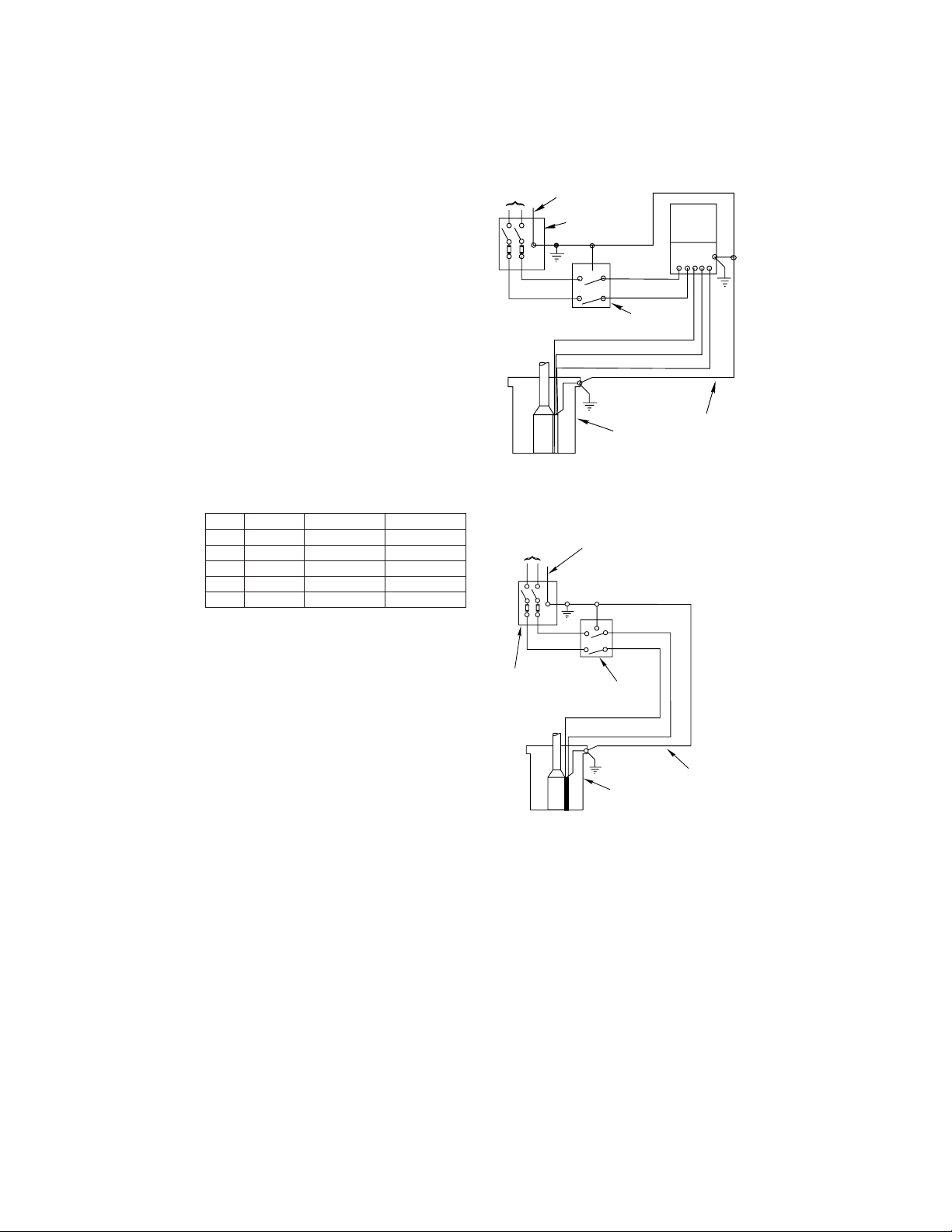
Wire control box as shown in Figures 1A and
1B. A 3-wire pump will not operate without
control box. Operation without control box will
burn out 3 wire motor.
Installation must include circuit and component
protection which meet local code and United
States National Electrical Code requirements.
If main overload trips, look for:
1. Shorted Capacitor
2. Voltage Problems
3. Overloaded or locked pump.
NOTICE: Match motor to control box as shown
below. Motor and control box model numbers
may include additional suffix numbers to the
right of the numbers shown here. These addi-
tional numbers are not important for control box
selection.
TABLE IV: Control Box Selection
4
HP Voltage Motor No. Control Box No.
1/2 115 214504 28010449
1/2 230 TES-00460053 SMCT-CR0521
3/4 230 TES-00460370 SMCT-CR0721
1 230 TES-00461320 SMCT-CR1021
1-1/2 230 TES-00461965 SMCT-CR1521
L1 M1
M2L2
Sub.
Motor
Control
L1L2RY B
Fused
disconnect
switch
115V or
230V Line
Ground
Red
Yellow
Black
Pressure
switch
Well
casing
Ground
FIGURE 1A - 3-wire quick disconnect box. Follow
color coding when connecting control box (Yellow to
Y, Red to R, Black to B).
L1 M1
M2L2
Fused
Disconnect
Switch
To Line
Ground
Red
Black
Pressure
Switch
Well
Casing
Ground
(Green)
336 1093
FIGURE 1B - Single phase, 2-wire connections. 2-wire
pumps have two power supply wire (Red/Black) and
one ground wire (Green). Control box is not required.
This is correct connection information for 115 and 230
volt 2-wire motors only.
Loading ...
Loading ...
Loading ...