
Loading ...
Loading ...
Loading ...
www.waynepumps.com
Operating Instructions and Parts Manual
4
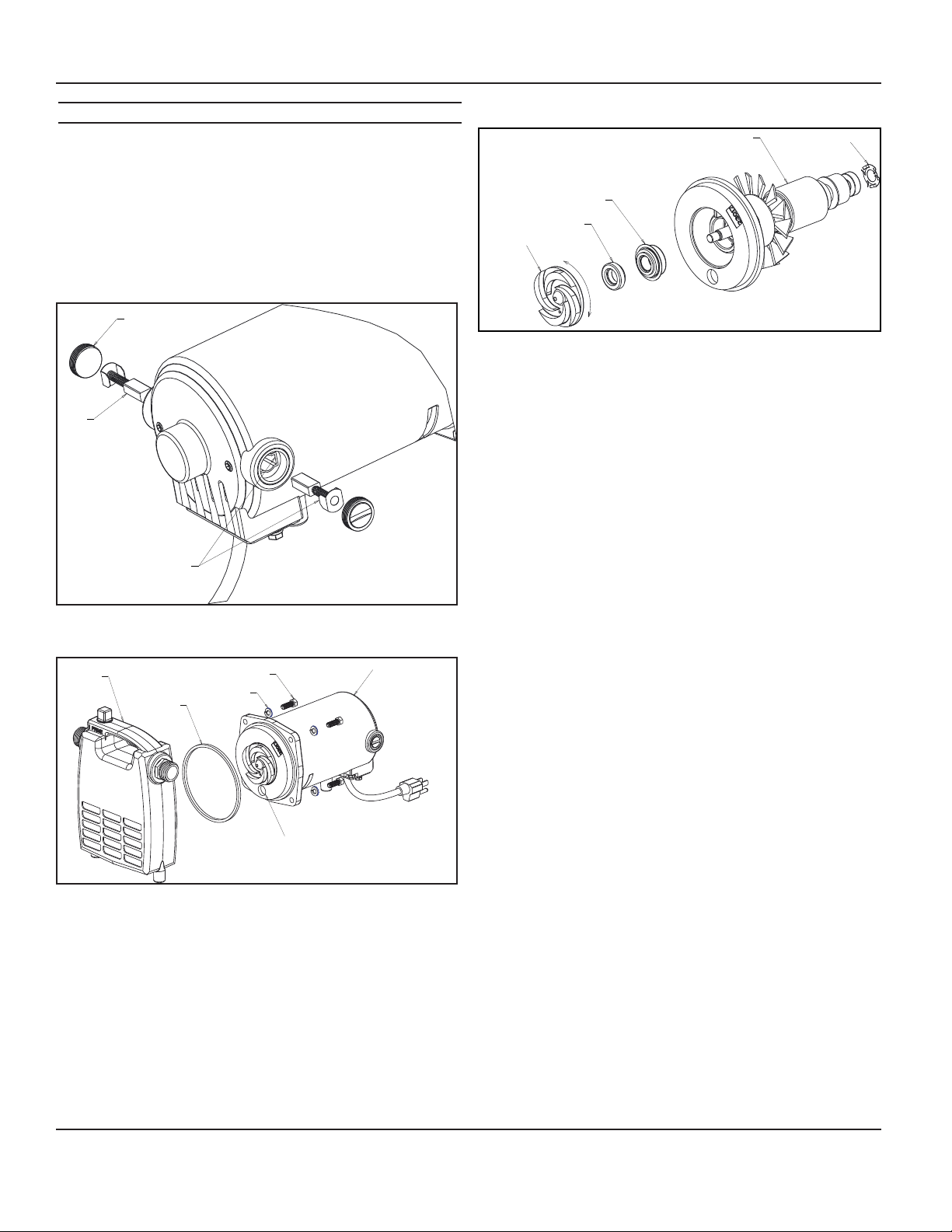
SERVICE PART REPLACEMENT
1. Make sure the pump is unplugged and cooled down before
disassembling the pump.
2. Release any pressure from the pump then disconnect any
hoses or plumbing, and drain the product.
3. Remove brush holder caps and brushes (make note of which
side of the pump the brush was in also the orientation of the
brush as you will want to put them back the same way they
came out.) Ref fig.3. Remove the (4) ¼-20 screws and lock
washers holding the volute to the motor housing. Ref fig.4
Figure 3
Figure 4
4. Remove the volute.
5. Remove the gasket and discard.
6. Remove the rotor assembly from the motor housing. There is
a thrust washer in the bearing pocket at the back of the motor
housing, if the thrust washer falls out make sure it is put back
into the pocket before reassembling. Ref fig.5
Figure 5
7. Holding the rotor assembly with one hand unscrew the impeller
from the rotor shaft. (Do not use a vise or other such device to
hold the rotor as it may damage the rotor.)
8. Remove both parts of the seal assembly from the back head
and impeller.
9. Push the new head seal (part with the blue metal housing) over
the rotor shaft and into the back head making sure the flange
on the seal seats against the back head and making sure the
black carbon side of the seal is facing away from the back head
towards the impeller.
10. Push the ceramic seal into the impeller pocket making sure the
white ceramic surface faces away from the back of the impeller.
11. Holding the rotor with one hand thread the new impeller onto
the rotor shaft making sure it is tight on the shaft and the white
face of the ceramic seal contacts the black carbon face of the
head seal.
12. Make sure the thrust washer is in the bearing pocket in the
back of the motor housing and guide the rotor assembly back
into the motor housing. Make sure the priming feature on the
back head is on the bottom of the pump, the pump won’t
prime properly if this isn’t in the correct location.
13. Put the new gasket on the motor housing then reattach the
volute to the motor housing using the four ¼-20 screws and
lock washers. Torque the screws to 75 in. lbs.
14. Replace the brushes and caps, make sure to put them back
in the same way they came out. Make sure the springs do not
pinch during assembly and align/center the tabs on the back of
the brush spring with the flats on the brush holder. Ref. fig.3
15. Test thoroughly and check for leaks before use.
BRUSH HOLDER CAP
BRUSH
ALIGN TABS ON BRUSH
WITH FLATS ON BRUSH HOLDER
1/4-20 SCREW
WASHER
GASKET
VOLUTE
PRIMING FEATURE
MOTOR HOUSING
LOOSE
TIGHT
THRUST WASHER
ROTOR ASSEMBLY
HEAD SEAL
CERAMIC SEAL
IMPELLER
Loading ...
Loading ...
Loading ...