Loading ...
Loading ...
Loading ...
BUFFMAX Use and Care Manual (May 2016) Page 5
Section 3: INSTALLATION
The manufacturer’s warranty does not cover any
damage or defect caused by installation, or
attachment, or use of any special attachment other
than those authorized by the manufacturer into,
onto, or in conjunction with the water heater. The
use of such unauthorized devices may shorten the
life of the unit and may endanger life and property.
The manufacturer disclaims any responsibility for
such loss or injury resulting from the use of such
unauthorized devices.
3.1 SAFETY MEASURES
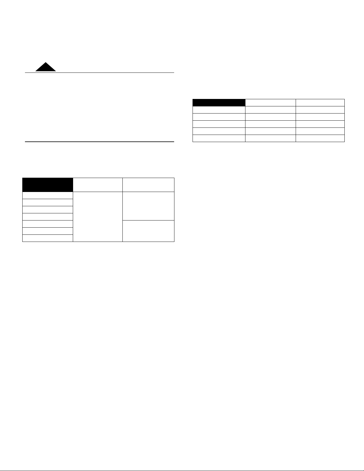
Here is a table for maximum operating temperature and
pressure for each BUFFMAX unit :
Maximum
Temperature
Maximum
Pressure
BUFFMAX 30
121°C (250°F)
150 psi
BUFFMAX 50
BUFFMAX 80
BUFFMAX 120
BUFFMAX 120A
125 psi
BUFFMAX 175A
BUFFMAX 200A
3.2 LOCATION
The BUFFMAX tank should be installed in a clean, dry
location. Long hot water lines should be insulated to
conserve water and energy. The tank and water lines
should be protected from exposure to freezing
temperatures.
The tank must be installed vertically and properly
leveled using the adjustment legs.
The tank must be located or protected so as not to be
subject to physical damage, for example, by moving
vehicles, area flooding, etc.
All models can be installed directly on a combustible
wall and into an alcove. The location must have
sufficient ventilation to maintain an ambient temperature
not exceeding 90°F (32°C).
3.3 CLEARANCES
Minimum clearances required for inspection and
servicing are the followings: (Supplementary clearances
may be required for piping installation)
Combustible
Maintenance
Left side
0 ‘’
3 ’’
Right side
0 ‘’
3 ’’
Top
0 ’’
3 ‘’
Bottom
0 ’’
6 ‘’
Back
0 ‘’
0 ‘’
3.4 INSTALLATION INSTRUCTIONS
1. Make sure the boiler is isolated from any water
input and output before starting to work on the
system.
2. Before connecting the BUFFMAX to the heating
system, make sure the tank is leveled. If
necessary, adjust the legs below the unit.
3. Connect the piping using the installation
drawings on the next pages.
4. When all the piping is connected, open the
water input and output valves of the tank. Make
sure to fill the tank completely.
To facilitate filling, partially unscrew the
hygroscopic cap on the top of the automatic air
vent on the top of the tank. When the tank is
completely filled, tighten the hygroscopic cap
and the automatic air vent will purge all
remaining air from the system.
5. Put the system back in operation. When
everything is operating, inspect all system
components to detect any leaking or problem
that could cause any eventual damage or
complications.
WARNING
!
Loading ...
Loading ...
Loading ...