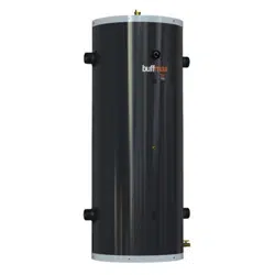
BUFFMAX
Buffer Tank
Storage Tank
Hydraulic Separator
USE AND CARE MANUAL
Including installation instructions for the contractor
Your BUFFMAX tank has been carefully assembled and factory tested to provide years of
trouble-free service. In order to insure the service intended, the following information is
provided to enable proper installation, operation, safety precautions and maintenance of this
product.
It is imperative that all persons who are expected to install, operate or adjust this tank read
the instructions carefully so that they may understand how to do so.
Any questions regarding the operation, maintenance, service or warranty of this tank should
be directed to the entity from whom it was purchased.
When all installation steps have been completed, replace this installation manual in its
original envelope, and keep in a safe place for future reference.
THERMO 2000 INC. revision : May 2016
Printed in Canada
BUFFMAX Use and Care Manual (May 2016) Page 2
General Safety Precautions
Be sure to read and understand the entire Use & Care Manual before attempting to install
or operate this tank. Pay particular attention to the following General Safety Precautions.
Failure to follow these warnings could cause property damage, bodily injury or death.
Should you have any problems understanding the instructions in this manual, STOP, and
get help from a qualified installer or technician.
Section 1: INTRODUCTION
The important safeguards and instructions
appearing in this manual are not meant to
cover all possible conditions and situations
that may occur. It should be understood that
common sense, caution and care are factors,
which cannot be built into every product.
These factors must be supplied by the
person(s) caring for and operating the unit.
1.1 LOCAL INSTALLATION
REGULATIONS
This BUFFMAX tank must be installed in
accordance with these instructions and in
conformity with local codes, or in the absence of
local codes, with the National Plumbing Code
and the National Electric Code, current edition. In
any case where instructions in this manual differ
from local or national codes, the local or national
codes take precedence.
1.2 CORROSIVE ENVIRONMENT
The tank must not be installed near an air duct
supplying corrosive atmosphere or with high
humidity content. When a tank defect is caused
by such conditions, the warranty will not apply.
1.3 INSPECTION UPON RECEPTION
Inspect the tank for possible shipping damage.
The manufacturer’s responsibility ceases upon
delivery of goods to the carrier in good condition.
Consignee must file any claims for damage,
shortage in shipments, or nondelivery
immediately against carrier.
1.4 TO BE CHECKED
Please check the identification tag on the unit to
make sure you have the right model.
The BUFFMAX tank is only designed to
contain boiler water in a closed circuit. In any
case, the tank must not be connected to an
atmospheric system or domestic hot water
supply.
!
WARNING
!
WARNING
!

BUFFMAX Use and Care Manual (May 2016) Page 3
Section 2: TECHNICAL SPECIFICATIONS
2.1 STANDARD EQUIPMENT
The following standard equipment is installed and
supplied with the tank:
4 standard size connections
½’’ NPT automatic air vent with shut-off
valve to facilitate replacement
2 ½’’ diameter temperature and pressure
indicator.
Immerson well
3 x ½’’ connections to localize well or
adding one
Fiberglass insulation limitating the heat
loss to½°F per hour
¾’’ Drain valve
Adjustment legs
Lifting lugs (ASME 120, 175 et 200
gallons models only)
2.2 OPTIONAL EQUIPMENT
The following items are optional on the tank;
Please see the engineering specifications for
more details about the product.
2 extra tappings
Custom tapping diameters
Class 150 Flange tappings
Elastomer insulation for chilled water
application avoiding condensation risk.
2.3 BUFFER TANK
The BUFFMAX optimizes runtimes and limits
on/off cycling of the energy source. When the
minimum system load is lower than the energy
source’s minimum capacity, the system will
generate short cycles. This causes premature
wear of the equipment and substantially
decreases the system’s energy efficiency.
2.4 STORAGE TANK
Any hydronic heating system with the BUFFMAX
stores energy like a battery. When a demand is
made for limited heating (for example, when
there is little difference between indoor and
outdoor temperatures) or when it is used with a
low-capacity energy source, the energy required
will first come from the tank’s thermal storage.
2.5 HYDRAULIC SEPARATOR
Adding a BUFFMAX tank to a hydronic heating
system helps to evacuate air, eliminates
impurities, and ensures the optimal functioning of
the pumps—not only for the energy source but
also for the distribution system.
BUFFMAX Use and Care Manual (May 2016) Page 4
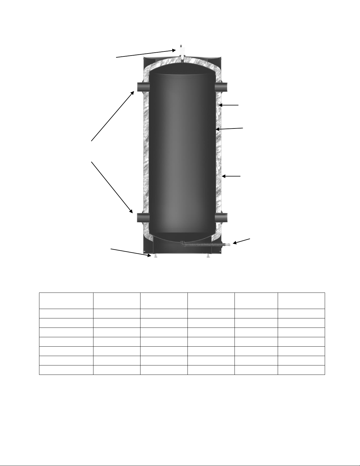
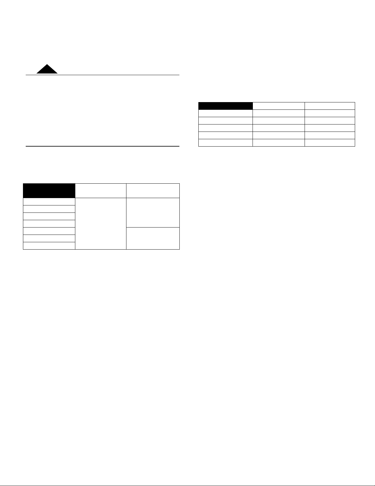
2.6 DIMENSIONS AND STANDARD CONNECTIONS*
Models
Tank Volume
Standard
Connections
Total Height
Diameter
Weight
BUFFMAX 30
30 gal. US
1 ½’’ NPTM
60 ¼‘‘
18’’
115 lbs
BUFFMAX 50
50 gal. US
2’’ NPTM
61 ¼‘‘
22‘‘
150 lbs
BUFFMAX 80
80 gal. US
2 ½’’ NPTM
75 ¾‘‘
24‘‘
235 lbs
BUFFMAX 120
119 gal. US
3’’ NPTM
77 ¾‘‘
28‘‘
315 lbs
BUFFMAX 120A
120 gal. US
3’’ NPTM
81-1/8‘‘
28’’
405 lbs
BUFFMAX 175A
175 gal. US
3’’ NPTM
85 ½‘‘
32’’
550 lbs
BUFFMAX 200A
200 gal. US
3’’ NPTM
93 ½‘‘
32’’
590 lbs
*Please see the engineering specifications for details about all available options.
Closed circuit
connections
Automatic air vent
(½’’ NPT)
2’’ Fiberglass
insulation
Steel tank
Steel jacket
Adjustable legs
Drain valve at the
bottom of the tank to
facilitate elimination of
impurities.
BUFFMAX Use and Care Manual (May 2016) Page 5
Section 3: INSTALLATION
The manufacturer’s warranty does not cover any
damage or defect caused by installation, or
attachment, or use of any special attachment other
than those authorized by the manufacturer into,
onto, or in conjunction with the water heater. The
use of such unauthorized devices may shorten the
life of the unit and may endanger life and property.
The manufacturer disclaims any responsibility for
such loss or injury resulting from the use of such
unauthorized devices.
3.1 SAFETY MEASURES
Here is a table for maximum operating temperature and
pressure for each BUFFMAX unit :
Maximum
Temperature
Maximum
Pressure
BUFFMAX 30
121°C (250°F)
150 psi
BUFFMAX 50
BUFFMAX 80
BUFFMAX 120
BUFFMAX 120A
125 psi
BUFFMAX 175A
BUFFMAX 200A
3.2 LOCATION
The BUFFMAX tank should be installed in a clean, dry
location. Long hot water lines should be insulated to
conserve water and energy. The tank and water lines
should be protected from exposure to freezing
temperatures.
The tank must be installed vertically and properly
leveled using the adjustment legs.
The tank must be located or protected so as not to be
subject to physical damage, for example, by moving
vehicles, area flooding, etc.
All models can be installed directly on a combustible
wall and into an alcove. The location must have
sufficient ventilation to maintain an ambient temperature
not exceeding 90°F (32°C).
3.3 CLEARANCES
Minimum clearances required for inspection and
servicing are the followings: (Supplementary clearances
may be required for piping installation)
Combustible
Maintenance
Left side
0 ‘’
3 ’’
Right side
0 ‘’
3 ’’
Top
0 ’’
3 ‘’
Bottom
0 ’’
6 ‘’
Back
0 ‘’
0 ‘’
3.4 INSTALLATION INSTRUCTIONS
1. Make sure the boiler is isolated from any water
input and output before starting to work on the
system.
2. Before connecting the BUFFMAX to the heating
system, make sure the tank is leveled. If
necessary, adjust the legs below the unit.
3. Connect the piping using the installation
drawings on the next pages.
4. When all the piping is connected, open the
water input and output valves of the tank. Make
sure to fill the tank completely.
To facilitate filling, partially unscrew the
hygroscopic cap on the top of the automatic air
vent on the top of the tank. When the tank is
completely filled, tighten the hygroscopic cap
and the automatic air vent will purge all
remaining air from the system.
5. Put the system back in operation. When
everything is operating, inspect all system
components to detect any leaking or problem
that could cause any eventual damage or
complications.
WARNING
!
BUFFMAX Use and Care Manual (May 2016) Page 6
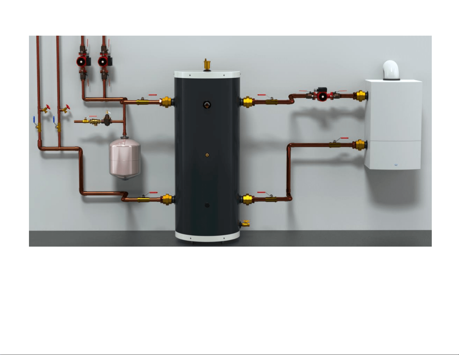
Figure 1: BUFFMAX Typical Installation
BUFFMAX Use and Care Manual (May 2016) Page 7
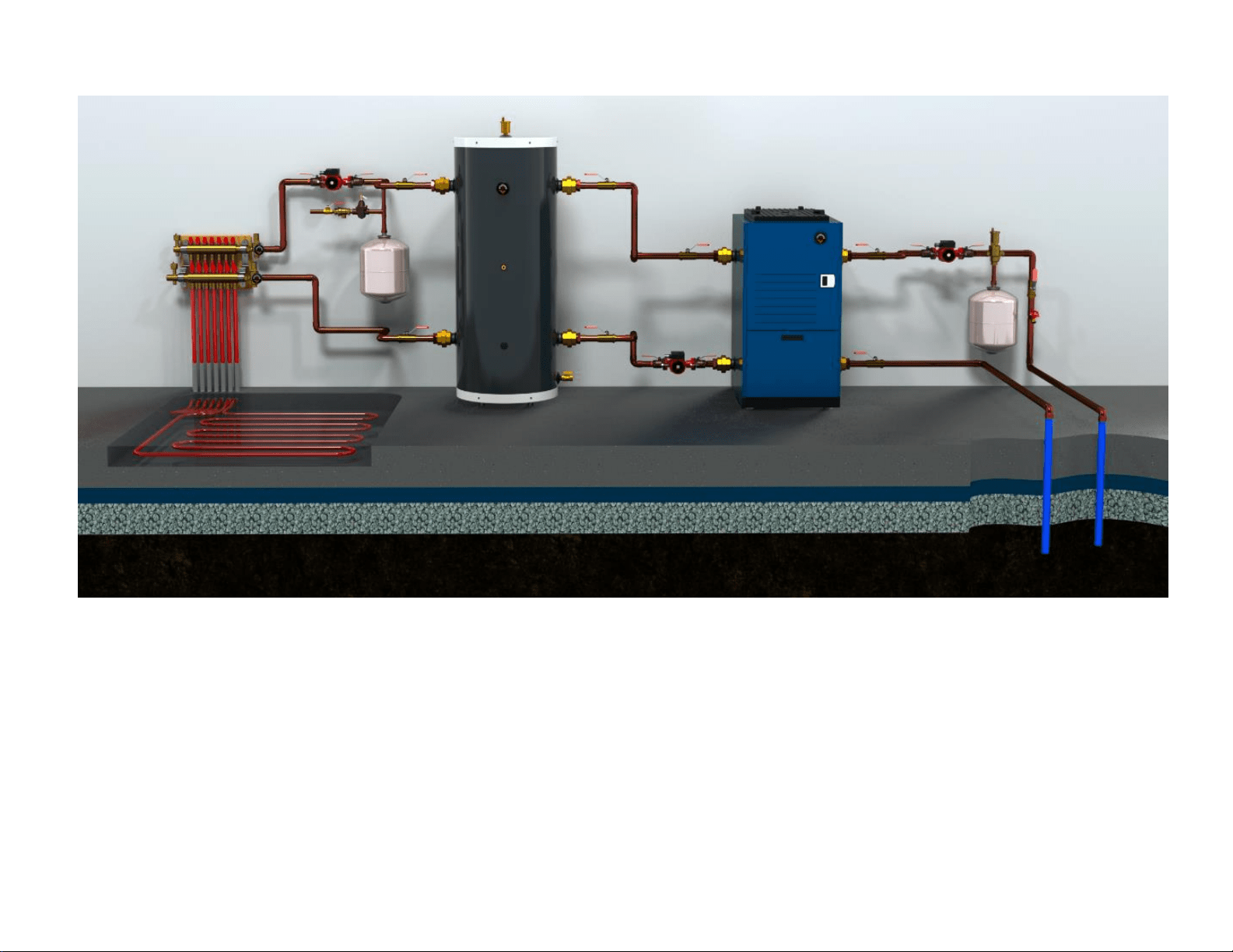
Figure 2: BUFFMAX Installation with geothermal system

BUFFMAX LIMITED WARRANTY
Warranty Coverage for Residential Installation.
Thermo 2000 Inc. hereby warrants to the original residential purchaser that the
BUFFMAX installed in a residential setting shall be free of leaks during normal use
and service for a period of ten (10) years from the date of purchase as long as the
original residential purchaser owns the home in which the unit was originally
installed. Residential setting shall mean usage in a single-family dwelling in which
the consumer resides on a permanent basis. Also, residential setting shall mean use
in multiple family dwellings in which one (1) Reserve is to be use in only one (1)
dwelling. In the event that a leak should develop and occur within this limited
warranty period due to defective material or workmanship, such leak having been
verified by an authorized company representative, Thermo 2000 inc. will repair or
replace at our sole option the failed unit with the nearest comparable model at the
time of replacement.
The original residential purchaser is responsible for all costs associated with the
removal and reinstallation, shipping and handling to and from manufacturing plant.
The replacement unit will be warranted for the remaining portion of the original
Warranty.
Warranty Coverage for Commercial Installation.
Thermo 2000 Inc. warrants to the original purchaser that the BUFFMAX installed in
a commercial setting for ten (10) years.
Commercial setting shall mean use in other than residential setting stated above in
the residential setting definition. In the event that a leak should develop and occur
within this limited warranty period due to defective material or workmanship, such
leak having been verified by an authorized company representative, Thermo 2000
inc. will repair or replace at our sole option the failed unit with the nearest
comparable model at the time of replacement.
The original purchaser is responsible for all costs associated with the removal and
reinstallation, shipping and handling to and from Manufacturer. The replacement
unit will be warranted for the remaining portion of the original Warranty.
Limited two years warranty on all RESERVE components
& parts
All other BUFFMAX components & parts are warranted for a period of two (2) years
against defects due to defective material or workmanship. The original purchaser is
responsible for all costs associated with the removal and reinstallation, shipping and
handling to and from Manufacturer. The components, repaired or replaced are
warranted for the residual period of the initial warranty on the unit.
Exclusions.
This warranty is void and shall not apply if:
1. Defects or malfunctions resulting from installation, repair, maintenance and/or usage
that are not done in conformity with the manufacturer’s installation manual; or
2. Defects or malfunctions resulting from installation, maintenance, or repair that are
not done in accordance with regulations in force; or
3. Defects or malfunctions resulting from improper installation, maintenance or repair
done carelessly or resulting from consumer damage (improper maintenance,
misuse, abuse, accident or alteration); or
4. Installation in which a relief valve (pressure) is not installed or if it is not functioning
properly, or when it is not connected to a drain to avoid damage to the property; or
5. Installation in which liquid circulating in the tank does not remain in closed circuit or
installation in which piping is leaking; or
6. A polybutylene pipe or radiant panel installation without an oxygen absorption
barrier is used; or
7. Installation where the acidity of water is not within the normal Environmental
Protection Agency (EPA) (between pH 6.5 – 8.5) guidelines or the water contains
abnormal levels of particulate matter or water exceeding 10.5 gpg; or
8. Your home contains any type of water softener system and the unit is not installed
and maintained in accordance with the manufacturer specifications; or
9. The BUFFMAX unit is being subject to non-authorized modifications; or
10. Defects or malfunction resulting of storing or handling done elsewhere than Thermo
2000’s manufacturing plant; or
11. Units on which the serial number is removed or obliterated.
Limitations.
Thermo 2000 shall not be responsible for any damage, loss, and inconvenience of any
nature whatsoever, directly or indirectly, relating to the breakdown or malfunction of the
unit. This warranty limits its beneficiary’s rights. Nevertheless, the beneficiary may have
other rights, which vary from state to state.
This warranty replaces any other expressed or implicit warranty and constitutes the sole
obligation of Thermo 2000 towards the consumer. The warranty does not cover cost of
removal, reinstallation or shipping to repair or replace the unit, nor administration fees
incurred by the original consumer purchaser.
Thermo 2000 reserves its rights to make changes in the details of design, construction, or
material, as shall in its judgment constitute an improvement of former practices.
This warranty is valid only for installations made within the territorial limits of Canada and
the United States.
Warranty service procedure
Only authorized Reserve dealers are permitted to perform warranty obligations. The
owner or its contractor must provide Thermo 2000’s head office or authorized depot with
defect unit together with the following information: BUFFMAX model and serial number,
copy of the original sales receipt and owner’s identification certificate.
THERMO 2OOO INC.
500, 9
th
Avenue, Richmond (Qc) Canada J0B 2H0
Phone: (819) 826-5613 Fax: (819) 826-6370
www.thermo2000.com
