Electric Boilers
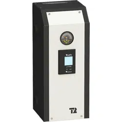
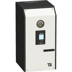
MINI ULTRA
Models from 3 kW to 12 kW : 208/240V single phase
INSTALLATION & OPERATING MANUAL
Your MINI ULTRA Electric Boiler has been carefully assembled and factory tested to provide
years of trouble-free service. The following information and safety measures are provided to
enable proper installation, operation, and maintenance of this product.
It is imperative that all persons who are expected to install, operate or adjust this boiler
should read these instructions carefully.
Any questions regarding the operation, maintenance, service or warranty of this electric
boiler should be directed to the supplier.
When all installation steps have been completed, keep this installation manual in a safe
place (close to the boiler) for future reference.
THERMO 2000 Inc. Revision: May 2015
Printed In Canada

MINI ULTRA ELECTRIC BOILERS Installation and operating manual (Revision: May 2015)
2
Table of contents
Section 1: TECHNICAL SPECIFICATIONS..............................................................................................4
Table 1: Ratings & Specifications at 208 & 240**Vac / 1ph
1
.................................................................4
Table 2 : Boiler connections and dimensions .......................................................................................4
Section 2: INTRODUCTION.....................................................................................................................5
2.1 LOCAL INSTALLATION REGULATIONS.......................................................................................5
2.2 CORROSIVE ENVIRONMENT......................................................................................................5
2.3 INSPECTION UPON RECEPTION................................................................................................5
2.4 TO BE CHECKED.........................................................................................................................5
Section 3 : INSTALLATION .....................................................................................................................6
3.1 SAFETY MEASURES....................................................................................................................6
3.2 LOCATION....................................................................................................................................6
3.3 CLEARANCES..............................................................................................................................6
Table 3: Boiler Clearances ..................................................................................................................6
3.4 BOILER WATER CONNECTIONS.................................................................................................7
3.4.1 Pressure relief valve...............................................................................................................8
3.4.2 Expansion tank.......................................................................................................................8
3.4.3 Water pressure regulator........................................................................................................8
3.4.4 Air eliminator..........................................................................................................................8
3.4.5 Circulating pump ....................................................................................................................8
3.4.6 Drain valve.............................................................................................................................9
3.4.7 Strainer ..................................................................................................................................9
3.5 ELECTRICAL CONNECTIONS......................................................................................................9
3.5.1 Main boiler supply...................................................................................................................9
3.5.2 Electrical supply of External accessories.................................................................................9
3.5.3 Outdoor temperature sensor...................................................................................................9
3.5.4 Thermostat(s) and pump(s) connections...............................................................................10
Section 4: ADJUSTMENTS OF THE CONTROL MODULE....................................................................12
4.1 INTRODUCTION.........................................................................................................................12
4.2 DISPLAYED INFORMATION.......................................................................................................12
4.3 OPERATION OF THE INTERFACE.............................................................................................13
4.4 OPERATION IN “FIXED BOILER TEMPERATURE SET POINT”.................................................13
4.5 OPERATION WITH “OUTDOOR RESET”....................................................................................13
4.6 PURGE DELAY OF THE PUMP..................................................................................................14
4.7 AUTOMATIC HEATING SHUT ....................................................................................................14
DOWN ..............................................................................................................................................14
4.8 CONFIGURATION OF THE CONTROLLER................................................................................14
4.8.1 Adjustments of the target temperature by the user................................................................15
4.8.2 ’’Boost system operation’’.....................................................................................................16
Section 5: START UP OPERATION.......................................................................................................17
5.1 PREPARATORY STEP ...............................................................................................................17
Section 6: MAINTENANCE....................................................................................................................18
6.1 INTRODUCTION.........................................................................................................................18
6.1.1 At all times............................................................................................................................18
6.1.2 Twice a year.........................................................................................................................18
6.1.3 Annually...............................................................................................................................18
6.2 REPLACEMENT PARTS.............................................................................................................19
Section 7 : TROUBLESHOOTING.........................................................................................................20
Table 4: Sensors resistance value vs real temperature......................................................................21
MINI ULTRA LIMITED WARRANTY ....................................................................................................22

MINI ULTRA ELECTRIC BOILERS Installation and operating manual (Revision: May 2015)
3
Figure 1 : Dimensions..............................................................................................................................1
Figure 2 : Mounting positions...................................................................................................................7
Figure 3 : Typical piping lay-out ...............................................................................................................7
Figure 4 : Typical installation on high temperature application..................................................................8
Figure 5 : Zoning with Multiple pumps....................................................................................................10
Figure 6 : Zoning with Motorized valves.................................................................................................10
Figure 7 : Wiring diagram (3-9 KW)........................................................................................................11
Figure 8 : Wiring diagram (12 KW).........................................................................................................11
Figure 9 : UltraSmart Controller Display.................................................................................................12
Figure 10 : UltraSmart Control Module...................................................................................................13
Figure 11 : Replacement Parts (Front view)...........................................................................................19
Figure 12 : Replacement Parts (Top view) .............................................................................................19
MINI ULTRA ELECTRIC BOILERS Installation and operating manual (Revision: May 2015)
4
Section 1: TECHNICAL SPECIFICATIONS
Table 1: Ratings & Specifications at 208 & 240**Vac / 1ph
1
Suggested size at
240V/1ph.
3
Capacity
(KW)
Amps
2
Cable
MINI ULTRA
208 V
240 V
208 V
240 V
Electric element(s)
(240 V)
Stages
Cu Al
Breaker
(Amp.)
3 2.2 3 10.9 12.5 1 x 3 KW 1 12 10 20
4.5 3.4 4.5 16.3 18.9 1 x 4.5 KW 1 10 10 30
6 4.5 6 21.8 25.0 2x 3 KW 1 8 6 40
7.5 5.6 7.5 27.2 31.2 1 x 3 KW + 1 x 4.5 KW 2 8 6 40
9 6.7 9 32.6 37.5 2 x 4.5 KW 2 8 6 50
12 9 12 43.5 50.0 2 x 6 KW 2 6 4 70
•
1
Electrical supply 120/240V or 120/208V – 1ph (L1-N-L2) with three conductors and a ground or
a supply with two conductors 240V or 208V – 1ph (L1-L2)with a ground if the application does not
require a 120V electrical supply for external accessories such as a pump, etc
•
2
Add the amperage of the circulating pump and other external accessories if they are connected
to the boiler (max. 5A).
•
3
A higher cable size could be required. In all cases the local electrical code has priority. The
electrician has the responsibility to select the appropriate size.
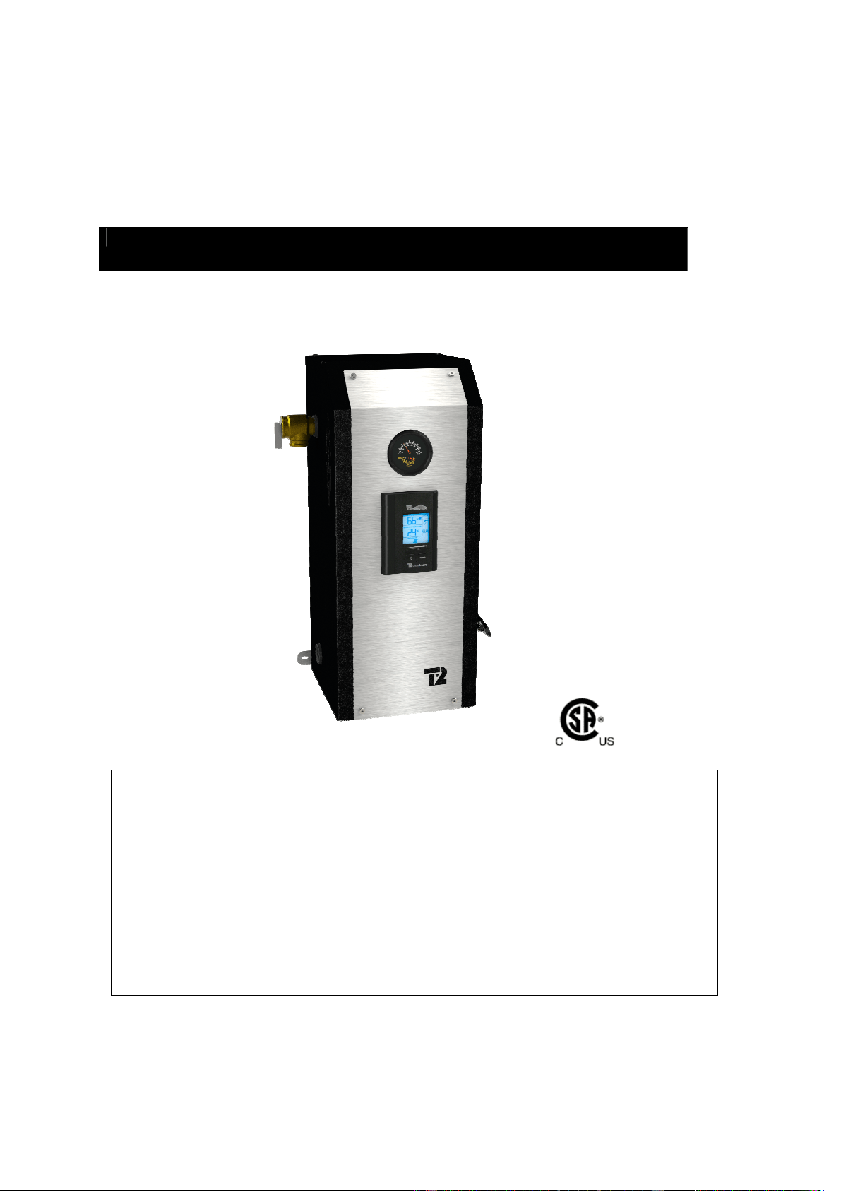
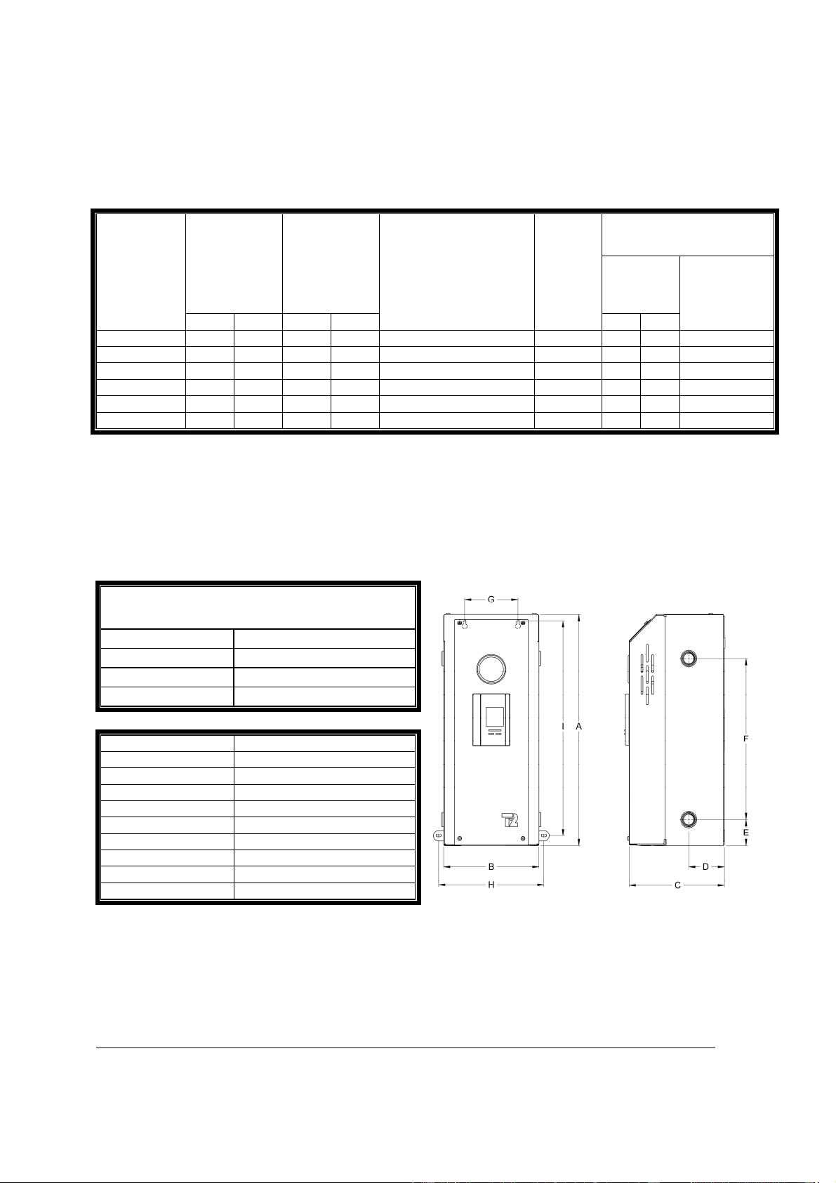
Table 2 : Boiler connections and dimensions
Connections
Inlet/Outlet 3/4 “ NPT Fem
Pressure relief valve
3/4 “ NPT Fem
Drain valve 3/4 “ NPT Fem
Shipping weight 47 lbs
Item
Dimension
(inches)
A 21-1/2
B 8-7/8
C 8-3/4
D 3-1/4
E 2-1/2
F 15
G 5
H 9-3/4
I 20
Some provinces or states, may require boilers built in conformity to ASME standards. If
such models are required, model with an “H” suffix shall be used.
Figure 1 : Dimensions
MINI ULTRA ELECTRIC BOILERS Installation and operating manual (Revision: May 2015)
5
General Safety Precautions
Be sure to read and understand the entire Installation & operation manual before attempting to
install or to operate this water heater. Pay particular attention to the following General Safety
Precautions. Failure to follow these warnings could cause property damage, bodily injury or
death. Should you have any problems understanding the instructions in this manual, STOP,
and get help from a qualified installer or technician.
Section 2: INTRODUCTION
These important safeguards and instruction appearing in this manual are not meant to cover all
possible conditions and situations that may occur. It should be understood that common sense,
caution and care are factors which cannot be built into every product. These factors must be
supplied by the person(s) caring for and operating the unit.
2.1 LOCAL INSTALLATION
REGULATIONS
This electric boiler must be installed in
accordance with these instructions and in
conformity with local codes, or in the absence of
local codes, with the National Plumbing Code
and the National Electric Code, current edition.
In any case where instructions in this manual
differ from local or national codes, the local or
national codes take precedence.
2.2 CORROSIVE ENVIRONMENT
The electric boiler must not be installed near an
air duct supplying corrosive atmosphere or with
high humidity content.
When a boiler defect is caused by such
conditions, the warranty will not apply.
2.3 INSPECTION UPON RECEPTION
Inspect the electric boiler for possible shipping
damage. The manufacturer’s responsibility
ceases upon delivery of goods to the carrier in
good condition. Consignee must file any claims
for damage, shortage in shipments, or non-
delivery immediately against carrier.
2.4 TO BE CHECKED
Please check the identification tag on the unit to
make sure you have the right model (Capacity in
kilowatt, voltage, number of phase).
List of components shipped with the unit :
• Pressure relief valve set at 30 PSI.
• Drain valve.
• Temperature & pressure indicator
• Outdoor temperature sensor
• Installation and operating manual
!
WARNING
!
MINI ULTRA ELECTRIC BOILERS Installation and operating manual (Revision: May 2015)
6
Section 3 : INSTALLATION
The manufacturer’s warranty does not cover any damage or defect caused by installation, or
attachment, or use of any special attachment other than those authorized by the manufacturer
into, onto, or in conjunction with the water heater. The use of such unauthorized devices may
shorten the life of the boiler and may endanger life and property. The manufacturer disclaims any
responsibility for such loss or injury resulting from the use of such unauthorized devices
3.1 SAFETY MEASURES
All installation will include the supplied pressure
relief valve which limits the maximum operating
pressure to 30psi (207kPa)
This electric boiler is designed to be installed on
a circuit operated between 50F to 190F (10C to
90C) and at a maximum operating pressure of
30psi (207kPa). The unit in designed solely to
be used on a close loop hydronic heating
system. The heat transfer solution must be a
solution of water or a mix solution Water/Glycol
having a maximum glycol concentration of 50%.
The boiler high limit temperature control is set at
a fixed temperature of 210F 99C). If the heating
distribution system on which the boiler is
installed requires a high limit controller having a
lower setting, this controller will be added to the
system and connected in series with the factory
installed limit control.
3.2 LOCATION
The electric boiler should be installed in a clean,
dry location. Long hot water lines should be
insulated to conserve water and energy. The
electric boiler and water lines should be
protected from exposure to freezing
temperature.
The boiler can be mounted vertically or
horizontally directly on a solid surface with 4
adequate screws inserted in the provided boiler
openings. Make sure it is properly leveled
The electric boiler must be located or protected
so as not to be subject to physical damage, for
example, by moving vehicles, area flooding, etc.
All models can be installed directly on a
combustible wall and into an alcove. The
location must have sufficient ventilation to
maintain an ambient temperature not exceeding
90F (32C).
The electric boiler should not be located in
an area where leakage of the tank or water
connections will result in damage to the
adjacent area or to lower floors of the
structure. When such areas cannot be
avoided, a suitable drain pan or non-
flammable catch pan, adequately drained
must be installed under the boiler.
The pan must be connected to a drain.
NOTE: Auxiliary catch pan MUST conform to
local codes.
3.3 CLEARANCES
For adequate inspection and servicing the
following minimum clearance is necessary:
Table 3: Boiler Clearances
Sides
3 inches
Electric elements side
14 inches
Front side of the boiler
3 inches*
Back
0 inches
*If the boiler is installed in a closed
compartment, allow an access service opening
and adequate ventilation to maintain an ambient
temperature lower than 90F/32C.
WARNING
!
CAUTION
!
MINI ULTRA ELECTRIC BOILERS Installation and operating manual (Revision: May 2015)
7
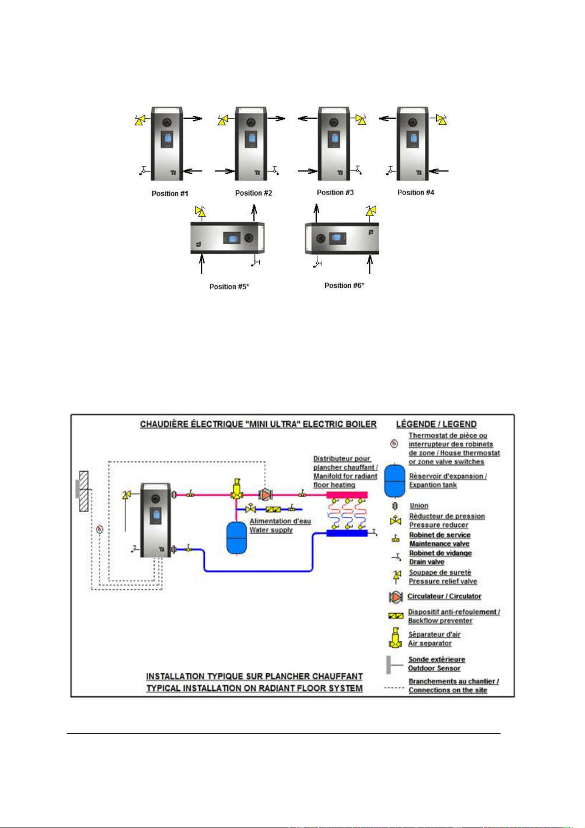
Figure 2 : Mounting positions
*In position #5 and #6: on boilers MINI ULTRA
3 & 4.5kW
, the heating element located in the upper section of the
boiler must be relocated into the lower opening.
3.4 BOILER WATER CONNECTIONS
Make sure you connect the accessories and the piping to the proper connection fittings as indicated at
figure 2 above and according to the selected mounting position.
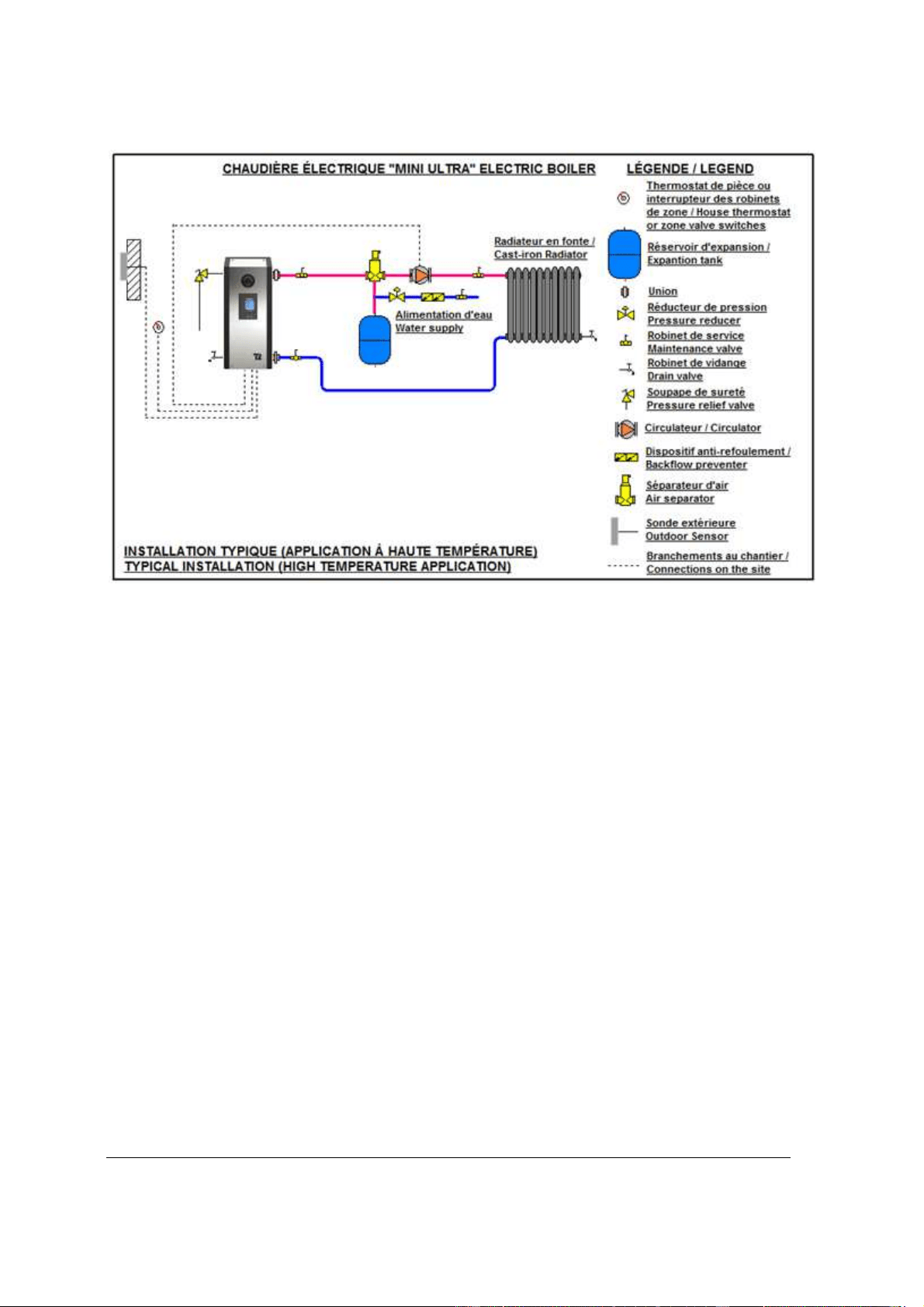
Figure 3 &4 below shows typical connections of a MINI BTH boiler to a radiant floor and cast iron radiator
heating systems. The location of the distribution system components may be different from what is
represented.
Figure 3 : Typical piping lay-out
MINI ULTRA ELECTRIC BOILERS Installation and operating manual (Revision: May 2015)
8
Figure 4 : Typical installation on high temperature application
3.4.1 Pressure relief valve
This component supplied with the unit must be
installed directly to the boiler housing to the
appropriate connection according to the mounting
position.
Connect the outlet of the relief valve downward to
a safe location in case of discharge.
The piping diameter used for the discharge piping
shall not be smaller than that of the valve outlet.
No valve of any type, restriction or reducer
coupling should be installed on the discharge line.
Local codes shall govern the installation of relief
valves.
3.4.2 Expansion tank
The expansion tank must be able to store the
increase volume of boiler water occurring when
the boiler water increase in temperature. The
maximum allowable operating pressure is 30PSI
(207kPa). Contact your plumbing supply house for
assistance.
3.4.3 Water pressure regulator
The boiler should be installed in such a way that it
can automatically be fed with water in the event of
a pressure drop.
The minimum pressure obtained when the system
is cold is generally 12 psi (83kPa).
This accessory shall be equipped with one or
more check valves to avoid all possibilities of the
boiler water returning to the potable water supply
network (local regulation should be applied)
3.4.4 Air eliminator
Installation of manual or automatic air vents are
required to eliminate all air from the boiler and the
heating distribution system.
The main air eliminator must be installed near the
outlet of the boiler on the highest point of the main
supply piping. It is imperative to insure that all air
possibly located in the boiler be eliminated at all
time.
3.4.5 Circulating pump
The pump shall be selected such as to be able to
supply adequate flow in relation to the heating
distribution system on which it will be connected
and the heating capacity of the boiler installed.
The table below will give you details on required
water flow for distribution systems having to
operate with a temperature differential of 10F and
20F between their inlet and outlet
.

MINI ULTRA ELECTRIC BOILERS Installation and operating manual (Revision: May 2015)
9
Your heating wholesaler shall be in good position
to recommend the appropriate model for your
application.
The pump motor capacity must not exceed 1/6HP
3.4.6 Drain valve
Installed at the lowest point of the unit, it allows
the unit to be drained for the eventual replacement
of a defective component.
3.4.7 Strainer
This component could be required on old heating
distribution systems made of steel or cast iron that
could carry sediments and sludge. If such
sediments accumulate at the bottom of the boiler it
could be harmful to the heat transfer of the
elements and generate premature failures.
3.5 ELECTRICAL CONNECTIONS
3.5.1 Main boiler supply
Boiler wiring and grounding must conform to the
National Electrical Code and to state or local code
requirements. The latter having precedence. The
electrical supply can be done in two different ways
depending on the necessity of supplying or not
external accessories (such as a pump) at 120Vac.
Alternative #1: A 120VAC electrical supply is
required to serve external accessories.
Electrical wiring must come from a 120/240 Vac/or
120/208Vac -1ph “L1-N-L2-” circuit protected by a
properly sized breaker.
Alternative #2: No 120Vac electrical supply is
required to serve external accessories (pump
is supplied by a separate circuit outside the
boiler)
Electrical wiring must come from a 240Vac or
208Vac- 1ph/60Hz “L1-L2” circuit protected by a
properly sized breaker.
Wire gauge must be properly sized by a qualified
electrician in such a way as to meet the national
electrical code.
To do so, consult the boiler rating plate which will
indicate the amperage drawn by the boiler at full
capacity. Extra amperage will have to be added if
external electrical equipments are connected to
the boiler.
This value and the electrical code will be used to
determine the electric cable required together with
the appropriate breaker.
Many other factors must be taken into
consideration in the selection of the appropriate
electrical material such as the length and the type
of cable used, the environment where the cable
will be installed and the type of the over-current
protection used.
The main terminal block of the boiler is suitable for
#14 to #2 wires.
Supply cables can be made of Aluminum or
Copper and be rated for a minimum of 75
o
C
(165
o
F).
If aluminum cables are used, it shall be of an
adequate size (generally bigger) and particular
consideration will have to be respected such as
the use of DE-OX inhibitors in order to meet the
National electrical code.
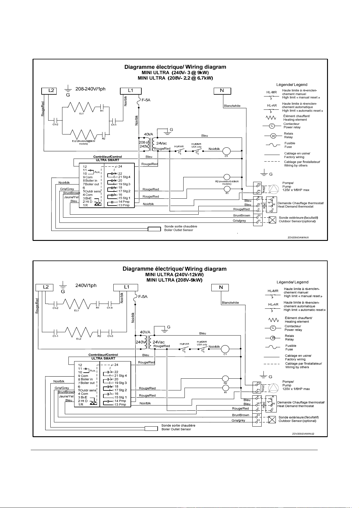
If the boiler electrical supply is on 208V, the
position of wire terminal on the transformer
connected to 240V will have to be changed to
208V.
3.5.2 Electrical supply of External
accessories
The total 120vac consumption of the boiler and
external accessories must not exceed 5A.
The maximum electrical consumption of 24vac
external accessories connected to R&C terminals
must not exceed 25VA.
3.5.3 Outdoor temperature sensor
If you want the boiler target temperature to
modulate according to the outdoor temperature
(when the outdoor temp. will get colder, the target
temp. will get higher). The supplied outdoor
sensor will have to be connected to S1 S1 before
turning the power on to the unit.
The installation of this sensor cancels the
operation of the boiler when the outdoor
temperature exceeds the selected value
corresponding to the maximum temperature
required for heating.
If you wish to operate the boiler at a fixed target
temperature, simply do not connect the sensor
before applying the power to the unit
The sensor shall be connected to terminals S1-S1
in the boiler using two 20 ga conductors.
Maximum length 100 ft. (33 m).
Do not put a jumper between S1&S1 if the outdoor
sensor is not used.
Model
Diff.10°F
usgpm
Diff. 20°F
usgpm
Boiler press.
loss
3 2.0 1.0 Insignificant
4.5 3.0 1.5
Insignificant
6 4.1 2.0
Insignificant
7.5 5.1 2.5
Insignificant
9 6.1 3.0
Insignificant
12 8.2 4.1
Insignificant
MINI ULTRA ELECTRIC BOILERS Installation and operating manual (Revision: May 2015)
10
3.5.4 Thermostat(s) and pump(s)
connections
Thermostat: Use a low voltage 24Vac thermostat
designed for central heating system (do not use a
240Vac thermostat designed for electric
baseboards).
Some thermostats are equipped with a
temperature sensor for radiant floor application.
The purpose of the thermostat is to give a signal
to the boiler that there is a demand for heat. When
the boiler will receive this signal, it will control the
activation of the heating elements.
A two stage thermostat can be installed to activate
the BOOST mode as shown in section 4.8.2.
Heating systems equipped with one
thermostat and one pump:
With an 18gauge cable, connect the room
thermostat directly to the following boiler
terminals.
Two wire thermostat: Terminals “R” and “W”
Three wire thermostat: Terminals “C”, “R” and “W”
Using 14 gauge wires, connect the circulating
pump directly on terminals “P” and “P
N.B. The amperage of the pump and 120Vac
accessories must not exceed 5A or 1/6HP
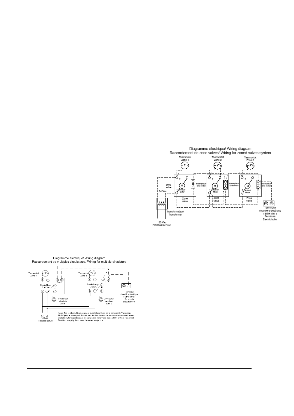
Multiple pumps zoning applications
Components shall be connected in such a way
that when a thermostat is generating a heat
demand, only the corresponding pump be
operated and that this heat demand is brought to
the boiler in order to activate the elements.
To do so, you will need relays as illustrated below.
Boiler terminals P-P will not be used.
Figure 5 : Zoning with Multiple pumps
Zoning applications with motorized valves
Connect the end switch contact of all motorized
valve to terminals R & W on the boiler.
Connect the circulator to terminals “P” and “P”- in
the boiler.
The connection of the thermostats to their
corresponding zone valve shall be done according
to the zone valve manufacturer’s instructions. See
on fig.5 below a typical example.
The R & C terminals on the boiler can be used to
supply 24Vac to the zone valves if the
corresponding load does not exceed 25VA.
Otherwise an external transformer will be
required.
Voltage at the outlet of the transformer shall never
be under 24Vac.
Figure 6 : Zoning with Motorized valves
MINI ULTRA ELECTRIC BOILERS Installation and operating manual (Revision: May 2015)
11
Figure 7 : Wiring diagram (3-9 KW
)
Figure 8 : Wiring diagram (12 KW)
MINI ULTRA ELECTRIC BOILERS Installation and operating manual (Revision: May 2015)
12
Section 4: ADJUSTMENTS OF THE CONTROL MODULE
4.1 INTRODUCTION
The MINI Ultra boiler is mainly designed to be
installed on closed circuit applications where the
water of the heating system flows directly from the
boiler to the heating distribution system (Standard
parallel Piping system)
Two operation modes are then offered:
Fixed boiler temperature set point (the
outdoor sensor shall not be installed)
Outdoor reset
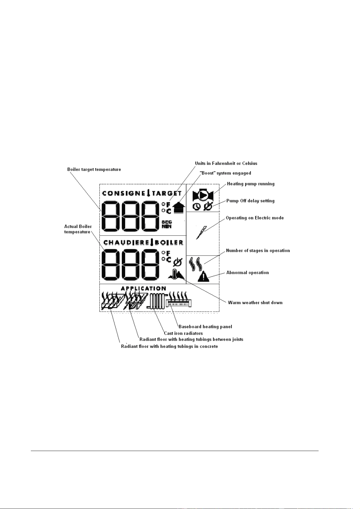
4.2 DISPLAYED INFORMATION
The electronic control uses an LCD display to make
all adjustments and to visualize the operation of the
system.
Figure 9 : UltraSmart Controller Display
MINI ULTRA ELECTRIC BOILERS Installation and operating manual (Revision: May 2015)
13
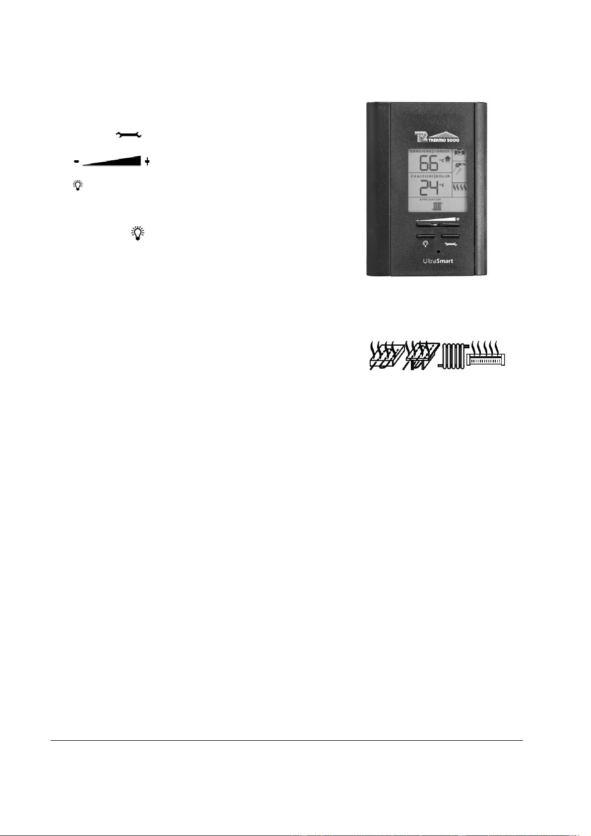
4.3 OPERATION OF THE INTERFACE
The controller uses four push buttons at the bottom
of the display to select and adjust the parameters.
The button is used to access to the
configuration menu and confirm a selection.
The buttons are used to select an
item or adjust a value.
The button enables the illumination of the display
under two different modes.
The default mode will enable the illumination of the
display for a period of 10 sec. each time a button is
pressed. If the is pushed, the light will be
continuously illuminated. Just press the button to
change the mode of activation.
Figure 10 : UltraSmart Control Module
4.4 OPERATION IN “FIXED BOILER
TEMPERATURE SET POINT”
For installation where the boiler target temperature
shall be maintained at a fixed temperature that will
not vary in relation to the outdoor temperature, the
sequence of operation will be as follow:
On a call for heat from the room thermostat, the
circulating pump will start and the boiler will activate
the number of stages required to get to and maintain
the outlet temperature of the boiler near the selected
target temperature. A rotation of the stages based
on an equal time period of operation is provided.
N.B. The supplied outdoor temperature sensor shall
not be connected before applying the electrical
power to the unit.
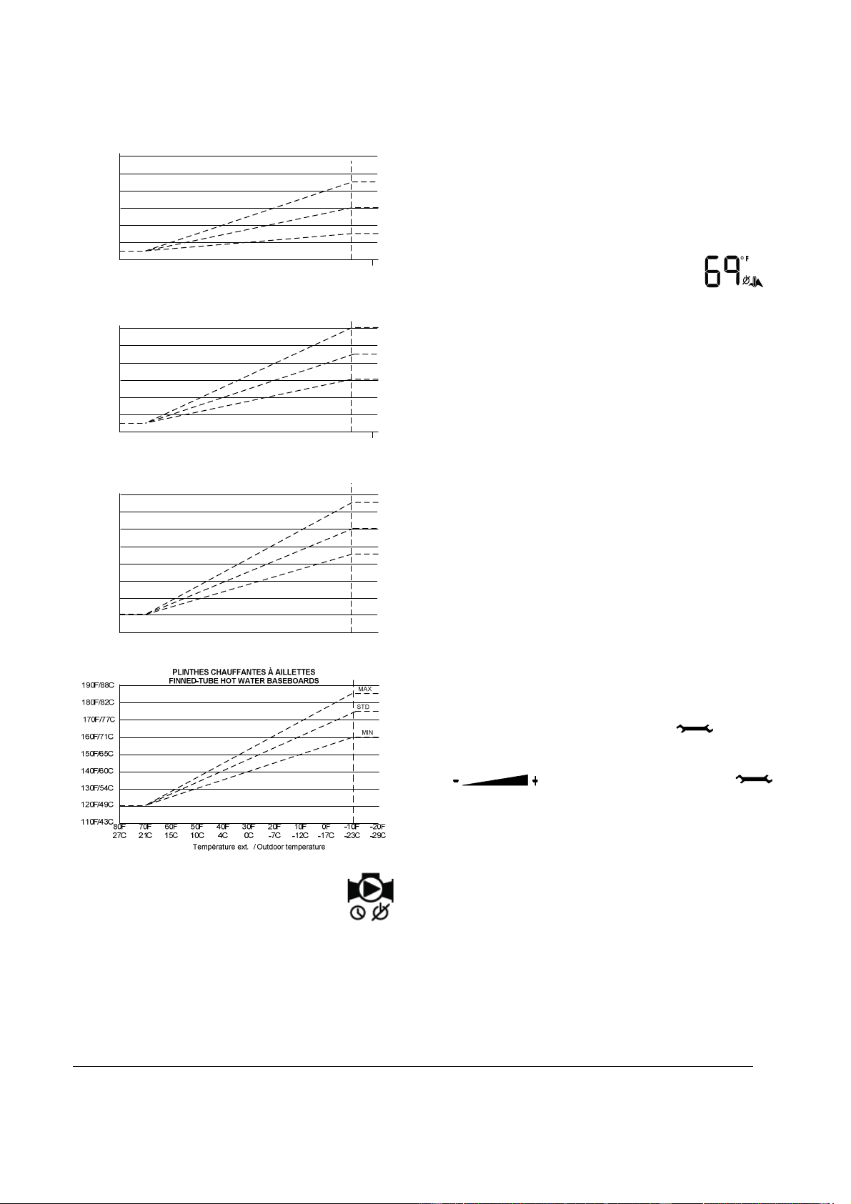
4.5 OPERATION WITH “OUTDOOR RESET”
For installation where the boiler target temperature
shall modulate in relation to the outdoor
temperature; when the outdoor temperature gets
colder, the boiler target temperature will increase.
On a call from the room thermostat, the circulating
pump will start and the boiler will activate the
number of stages required to get to and maintain the
outlet boiler temperature near the target temperature
established by the controller according to the
outdoor temperature. A rotation of the stages based
on an equal time period of operation is provided.
N.B. The supplied outdoor temperature sensor must
be connected before applying the electrical power to
the unit.
The boiler target temperature will be calculated by
the controller in relation to the parameters selected
in the menu and the
maximum target temperature required when the
outdoor temperature will get to -10F (-23C). The
“STD” curve corresponds to the default maximum
temperature for a typical system and this value can
be modified from the “MIN” to “MAX” value shown on
the following tables.
The following tables show the values of the target
temperature that will be obtained in relation to the
outdoor temperature.
MINI ULTRA ELECTRIC BOILERS Installation and operating manual (Revision: May 2015)
14
80F
27C
70F
21C
60F
15C
50F
10C
10F
-12C
40F
4C
30F
0C
20F
-7C
0F
-17C
-10F
-23C
-20F
-29C
70F/21C
80F/27C
100F/-38C
90F/32C
110F/43C
120F/49C
130F/54C
Température ext. / Outdoor temperature
Temp. de consigne / Target temp.
STD
MAX
MIN
PLANCHER CHAUFFANT DANS BÉTON
RADIANT FLOOR IN CONCRETE
80F
27C
70F
21C
60F
15C
50F
10C
10F
-12C
40F
4C
30F
0C
20F
-7C
0F
-17C
-10F
-23C
-20F
-29C
100F/-38C
90F/32C
110F/43C
120F/49C
130F/54C
Température ext. / Outdoor temperature
Temp. de consigne / Target temp.
STD
MAX
MIN
PLANCHER CHAUFFANT ENTRE SOLIVES
RADIANT FLOOR BETWEEN JOISTS
140F/60C
80F/27C
80F
27C
70F
21C
60F
15C
50F
10C
10F
-12C
40F
4C
30F
0C
20F
-7C
0F
-17C
-10F
-23C
-20F
-29C
100F/-38C
90F/32C
110F/43C
120F/49C
130F/54C
Température ext. / Outdoor temperature
Temp. de consigne / Target temp.
STD
MAX
MIN
RADIATEURS EN FONTE
CAST IRON RADIATORS
140F/60C
150F/65C
160F/71C
170F/77C
Temp. de consigne / Target temp.
4.6 PURGE DELAY OF THE PUMP
The controller offers the possibility to
stop the operation of the pump after an adjustable
delay once the heat demand has been completed.
The following choices are offered:
“OFF” The pump will stop immediately when the
heat demand has been satisfied. This selection
shall be selected on systems equipped with
motorised fast closing time zone valves with in
order to prevent noise from water hammering.
“15 sec to 60min”: delay where the pump will be
kept running to enable the pump to circulate
water into the system to equilibrate the heat in
all the building.
“ON”: The pump is in continuous operation.
Required on particular heating distribution
systems.
4.7 AUTOMATIC HEATING SHUT
DOWN
When the outdoor sensor is installed and that the
unit then operates in the “outdoor reset” mode, the
controller offers the user the possibility to
automatically stop the boiler when the outdoor
temperature reaches an adjustable value (0F (-17C)
à 105F (40C). This characteristic is especially
interesting on the following applications:
Heating systems equipped with many
thermostats where the user wants to prevent
the operation of the unit if one of the
thermostats has inadvertently been activated.
Heating systems where the owner supplies heat
to a lodger.
Systems connected to a geothermic heat pump
where we do not want the electric boiler to be
operating unless the outdoor temperature drops
to a selected degree.
4.8 CONFIGURATION OF THE
CONTROLLER
Since each type of heating distribution system is
designed to operate at water temperatures that are
particular to its operation, the proper configuration of
the operating parameters of this particular system is
important to maximize its performance.
In order to do this, the installer will access the
configuration menu by pressing the button for
2 sec. until the first menu appears. The selection of
the item or value is made by pressing the
button and by pressing the
button to get to the next menu. See table 1 below to
visualize the menu list that will gradually be
displayed.
If the buttons remain untouched for a period of 10
sec., the controller will register the value of the
selection made and return to the regular display
position. It will also return to the regular display after
reviewing all the operating parameters of the
controller.
In case of a power failure, the parameters will be
restored as they were established before the failure.
MINI ULTRA ELECTRIC BOILERS Installation and operating manual (Revision: May 2015)
15
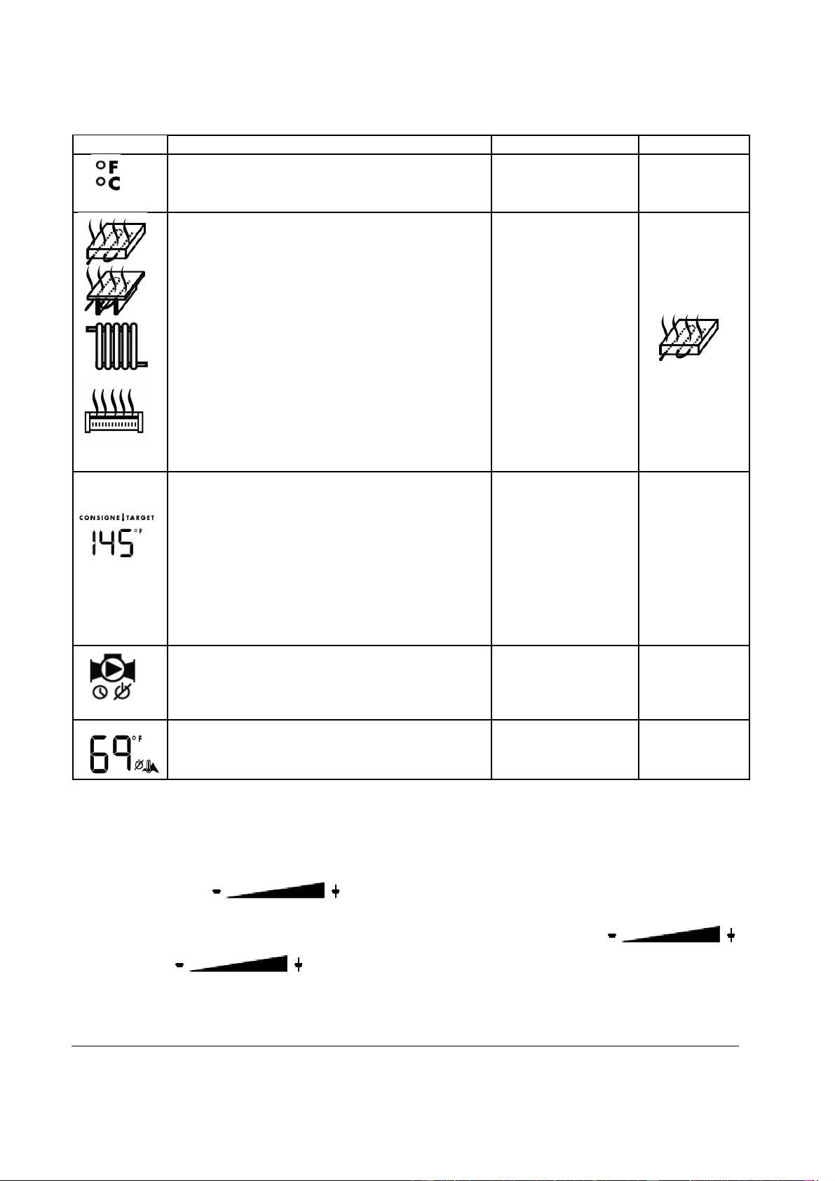
ITEM DESCRIPTION CHOICE DEFAULT
Choose the units the user prefers to work with °F or °C °F
Select the type of heating system on which the
boiler will be installed.
Radiant Floor in
concrete
Radiant Floor
between joists
Ca
st iron radiator
Hot water
baseboards
Adjust the maximum boiler target temperature
required to adequately heat the building when the
outdoor temperature is very cold.
Radiant Floor in
concrete
(85°F to 105°F)
Radiant Floor
between joists
(110°F to 140°F
)
Cast iron radiator
(135°F to 165°F)
Baseboard
(160°F to 185°F)
100°F
125°F
150°F
175°F
Select the purge period that the pump will be
running once the heat demand is completed. Select
OFF if the heat system is equipped with electric
zone valves.
OFF
15 sec. to 60
min.
ON
30 sec.
Select the outdoor temperature at which no heating
of the building is required (the outdoor sensor has
to be installed)
0°F to 105°F 75°F
Note1: Once these parameters have been set, the controller will automatically return to its normal view but
the user has the possibility to change the target temperature without having to go through the complete
menus.
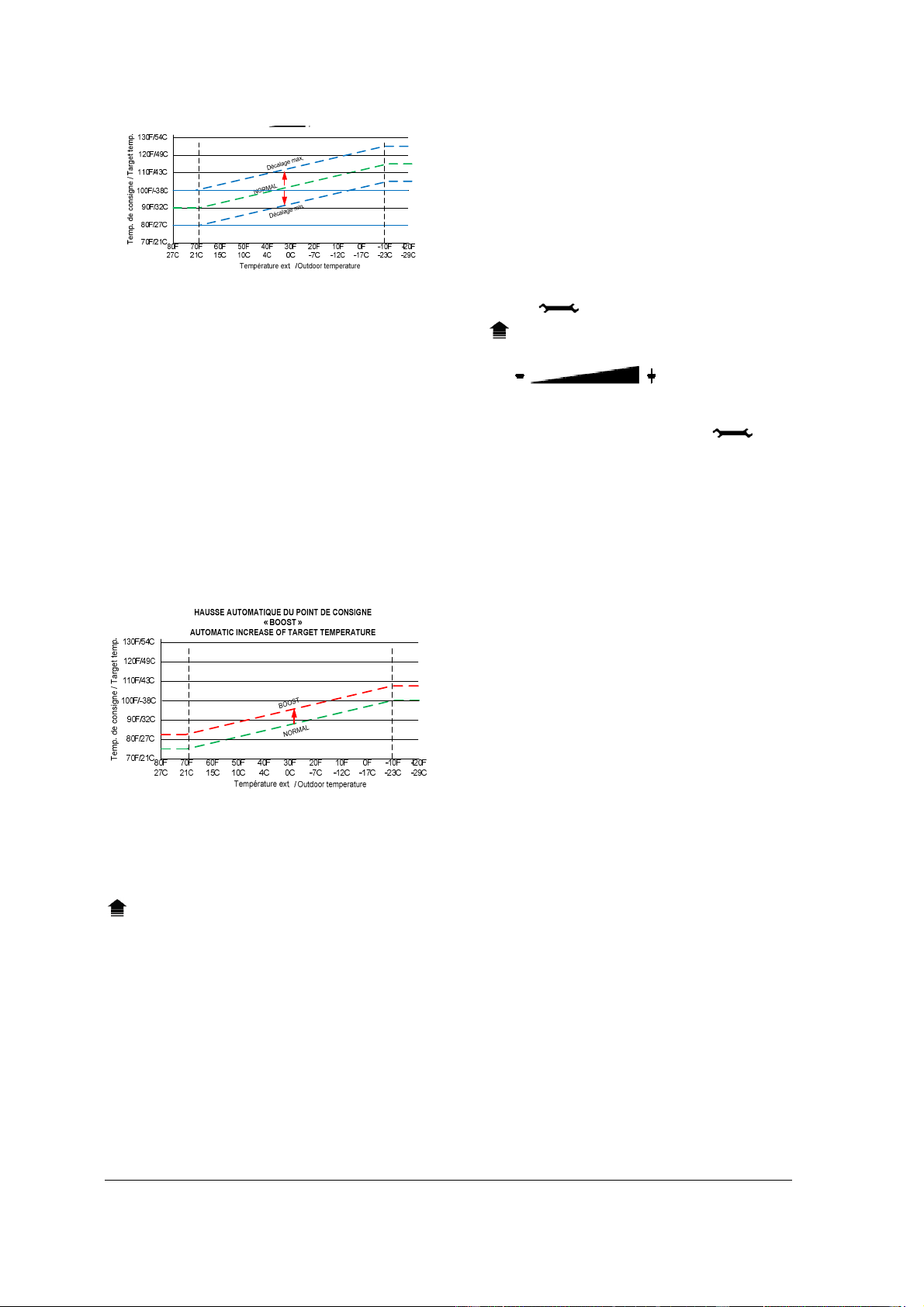
4.8.1 Adjustments of the target
temperature by the user
By pressing the the end
user has the possibility to offset the programmed
target temperature without going through the tool
menus.
When the button is
pressed, the value “0” will appear and blink to
show a “0” offset value from the original settings.
When the + or- buttons are pressed again the
offset value will change up to a value of +/- 10°F
(5°C) from the original setting made in the
configuration menu. The new value will blink
during 5 sec. and the display will then go back to
the standard view and the new target
temperature will be shown.
Afterward, when the
button will be pressed, it will show the value of
the offset made previously and can be re-
adjusted.
MINI ULTRA ELECTRIC BOILERS Installation and operating manual (Revision: May 2015)
16
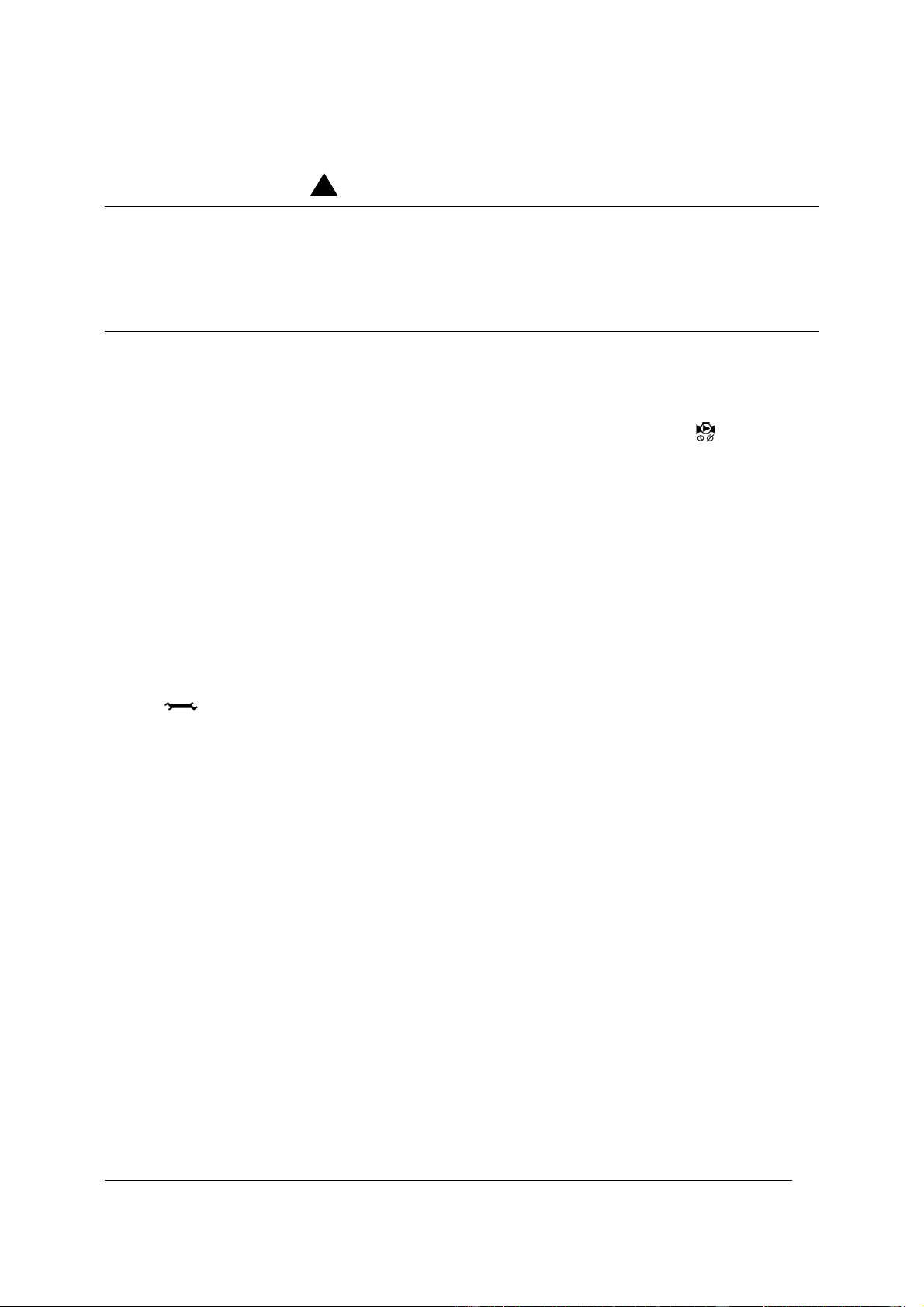
4.8.2 ’’Boost system operation’’
The controller incorporates a unique feature that
enables the target boiler temperature to
automatically be increased when the building
heat load increases but cannot be fulfilled with
the actual boiler target temperature and
consequently the room thermostat(s) cannot be
satisfied within a pre-determined period.
Example :
Return to normal heat load after low
demand periods occurring during sunny
days.
Long periods without heating which
needs higher boiler temperature to
recuperate.
Return to normal room temperature after
thermostat’s “nights set back” program.
The controller will engage the “Boost” program
when the heat demand on terminals W&R has
been maintained for a pre-determined period
according to the type of selected application.
Once this period has been reached, the “Boost”
icon will appear on the display and the boiler
target temperature will start increasing very
slowly over a pre-determined period and up to a
pre-calculated maximum value until the heat
demand applied on W&R terminals has been
completed.
On a new heat demand, the previous boost
period is forgotten and the boiler target gets
back to its original setting
If the system is in “boost” most of the time, this
means that the boiler target parameter
established during “Setting procedure” would be
too low for the heating system on which the unit
is applied. This boiler target could simply be
gradually increased by pressing the + button or
by re-setting the operating parameters using the
tool menus.
N.B. The boost program is a marvellous feature
that works fine on applications where the
number of room thermostats is in limited quantity
otherwise it may happen that during very cold
periods the heat demand from all the
thermostats may not become satisfied.
If your application needs the boost program to
be cancelled, you can do it by pressing the
button for 6 sec. and the display will show
icon and the two options ON or OFF will blink
and can be selected using
the button. The controller
will register the selected option and return to
normal operation if the buttons remains
untouched for 5 sec. or if the button is
pressed.
MINI ULTRA ELECTRIC BOILERS Installation and operating manual (Revision: May 2015)
17
Section 5: START UP OPERATION
Before operating this boiler, be sure to read and follow these instructions, as well as the warnings
printed in this manual. Failure to do so can result in unsafe operation of the boiler resulting in
property damage, bodily injury, or death. Should you have any problems reading, following or
difficulty in understanding the instructions in this manual, STOP, and get help from a qualified
person.
Do not turn on the boiler unless it is filled with water. Do not turn on the boiler if the cold water
supply shut-off valve is closed.
5.1 PREPARATORY STEP
Make sure that all the piping and
electrical connections have been made.
Fill the boiler and the heating system
with water.
Check for leaks.
Check the pressure reading at the
temperature and pressure indicator. It
should be around 12 psi.
Turn On the electrical supply to the
boiler with no heat demand from the
thermostat(s).
Completely eliminate all the air from the
boiler and the distribution piping system.
To do so, activate the circulating pump
without the heating elements. If the
pump is connected directly on PP
terminals of the boiler, it can be
activated by selecting “ON” in the
configuration menu after having pressed
for 2 seconds.
Adjust the UltraSmart boiler temperature
controller as explained earlier and set
the purge delay of the pump from On to
its normal operation setting.
Set the room thermostat ON to generate
a heat demand. The pump shall start.
The heating elements shall gradually
come on and the boiler temperature will
increase.
5.2 STARTUP & INSPECTION
Measure the amperage value drawn by
the unit. It shall be around the value
indicated on the boiler name plate.
Partially close the isolating valve at the
outlet of the boiler to reduce the water
flow and consequently slowly increase
the outlet temperature. The heating
elements shall gradually stop as the
temperature increases and gets near the
target temperature.
Lower the adjustment of the room
thermostat(s). The heating elements
shall stop and the pump shall stop after
the delay set on the controller.
Check the pressure reading on the
gauge of the unit. It should not be higher
than 28 psi when the distribution system
will get to its maximum operating
temperature.
N.B. On initial startup it may take a considerable
amount of time before the water reaches the
target temperature
Further adjustments may be necessary as you
use your boiler and the space heating system.
SAFETY PRECAUTIONS
!

MINI ULTRA ELECTRIC BOILERS Installation and operating manual (Revision: May 2015)
18
Section 6: MAINTENANCE
6.1 INTRODUCTION
Properly maintained, your boiler will provide
years of dependable, trouble free service. It is
recommended that a regular routine
maintenance program be established and
followed by the user. Components are subject to
eventual failure that requires service. Failure to
use the correct procedures or parts in these
circumstances may make the unit unsafe or
reduce the life of the boiler. The owner should
have the following inspection and maintenance
procedures performed:
6.1.1 At all times
An immediate inspection should be made if:
An odor of melted plastic or overheated
material is detected
A leak coming from the unit or the
heating system is observed
If a leak is detected at the outlet of the safety
relief valve, it could be related to a problem with
certain components installed on your heating
distribution system. A quick correction is then
required.
Do not plug the outlet of this safety relief valve if
a dripping condition occurs.
6.1.2 Twice a year
Check for the proper operation of the
automatic air purger(s) and eliminate air
from the radiators.
6.1.3 Annually
It is recommended that a visual
inspection be made on the electrical
compartments of the boiler to check the
water tightness of the gasket on the
element flange and also check for any
signs of overheating of the components
and wires. Required corrections should
be made as soon as possible.
Parts used for replacement should be
the same as the original equipment.
Make sure that the power on the unit has
been turned off before opening the electrical
compartments of the boiler.
Close isolating valves and clean the
strainer located on the heating return
piping.
Open the boiler drain valve to eliminate
deposits that could have settled at the
bottom of the boiler. Stop when water
gets clear. If there is no flow or a very
small flow, it could be due to a large
accumulation of deposits at the bottom
of the unit. If so, close the isolating
valves at the inlet and outlet of the
boiler, remove heating element(s) and
clean the inside of the tank with a
strong jet of water.
WARNING
!
MINI ULTRA ELECTRIC BOILERS Installation and operating manual (Revision: May 2015)
19
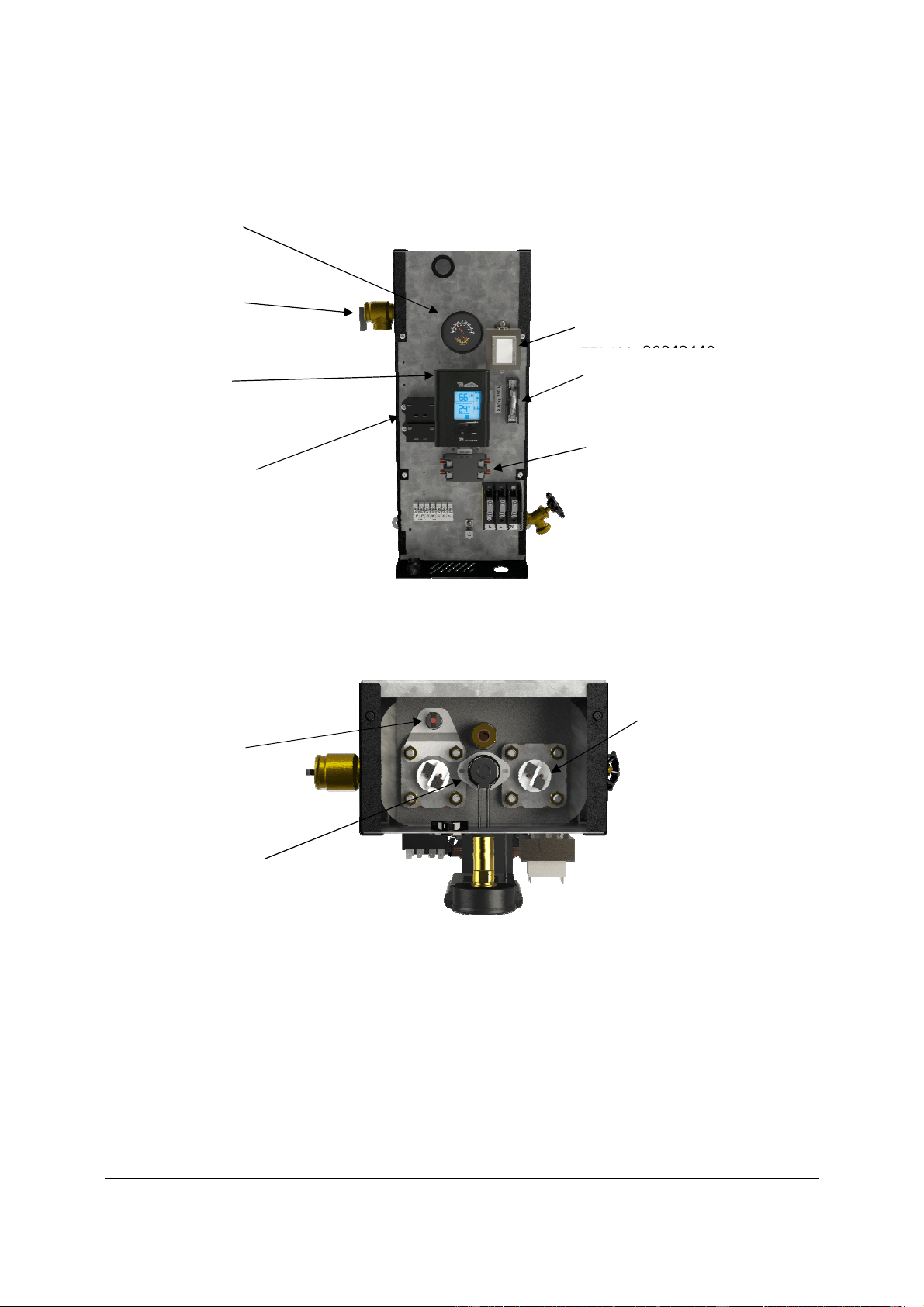
6.2 REPLACEMENT PARTS
Figure 11 : Replacement Parts (Front view)
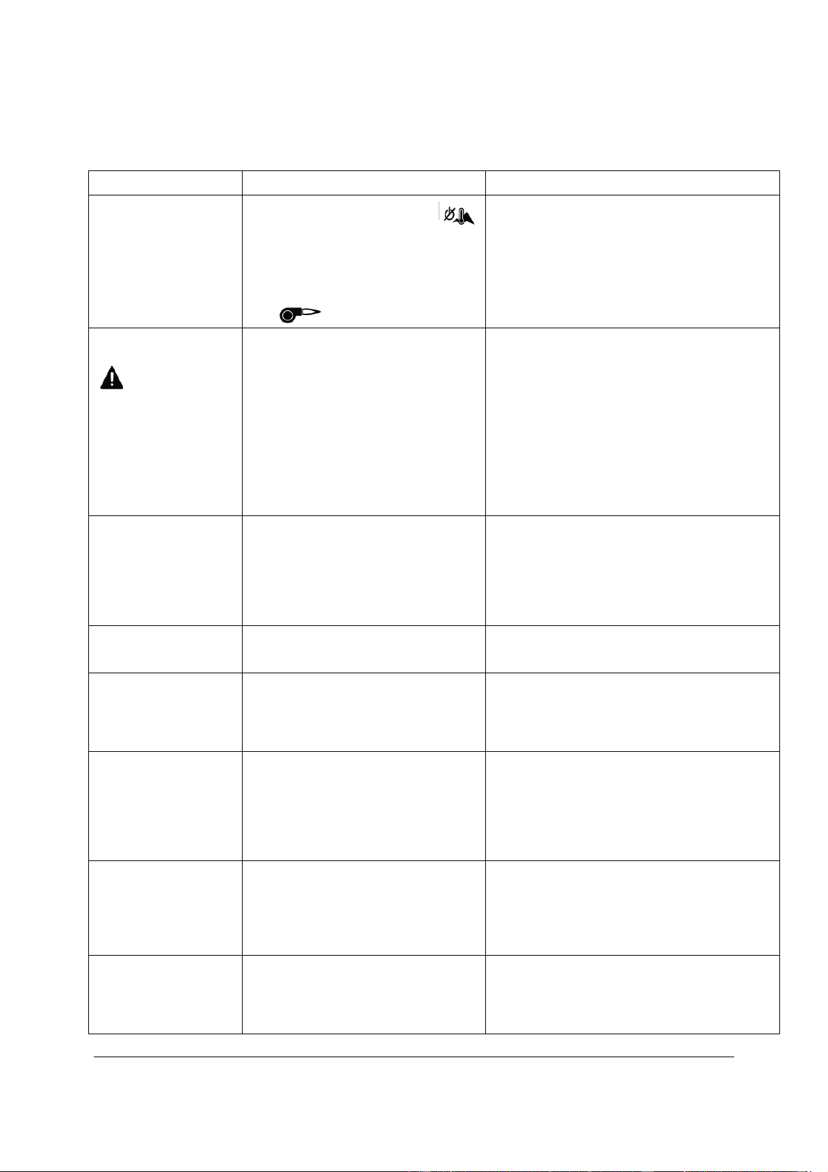
Figure 12 : Replacement Parts (Top view)
** When replacing a heating element, make sure to install it in the same orientation it was installed at the factory.
Heating Elements
**
3 kW : ZEL300-240V3KW
4.5 kW : ZEL300-240V45KW
6 kW : ZEL300-240V6KW
Fuse
ZEL250-TDMIDJ5
High
-
Limit automatic
reset Switch
ZEL200-L6C732
Power Relays 24Vac
ZEL100-24ACNO30
Pressure Relief
Valve
ZMC200-SV30PSI1
2 Poles Contactor 24Vac
(3, 4.5, 6, 7.5, 9 kW)
ZEL100-2PC5024
4 poles Contactor 24Vac
(12 kW)
ZEL100-4P50A24
Transformer 208/240Vx24V
(40va)
ZEL400
-
20842440
Temperature and
Pressure Indicator
ZMC300-75P160CN
Control Module
ZEL100-ULTRA
Surface High
-
Limit
manual reset switch
(USA Models only)
ZEL200
-
DISC227
MINI ULTRA ELECTRIC BOILERS Installation and operating manual (Revision: May 2015)
20
Section 7 : TROUBLESHOOTING
PROBLEM CAUSES SOLUTION
The display shows
---
in “TARGET TEMP”
-There is no heating demand
-When the outdoor sensor
is used and the icon is shown, the
outside temperature is above the
boiler shut down setting.
-The switch located on the back of the
controller is set to “Bi-Energ” and the
icon is shown.
-Generate a heat demand
-Temporarily increase the value of this setting
on the controller configuration.
-Set the switch to “Elect”
The display shows
“Er1”
and the icon
is displayed.
The controller is not detecting the
presence of the outdoor sensor.
-Make sure that the sensor cable connected to
the unit is not in short or open circuit. Do not
install a jumper between S1-S1 when the
sensor is not required.
-Check the resistance value (ohms) of the
sensor. It should correspond to the value
shown on the table below otherwise it should
be replaced.
Check for proper connection of the wires
inside the boiler connected to S1S1 and at the
controller terminals.
The display shows
“
Er2
” and blinks
The controller is not detecting the
presence of the boiler temperature
sensor.
-Check the state of the sensor located in the
immersion well located at the top of the
electrical element compartment.
-Check the resistance value (ohms) of the
sensor. It should correspond to the value
shown on the table below otherwise it should
be replaced.
Stage 2 is ON but not
Stage 1
There is no problem. A rotation of the
stages is provided to allow an equal
time of operation of the stages.
The boiler target
temperature does not
change when the
outdoor temperature
varies.
The outdoor sensor has not been
detected when the power has been
applied to the unit.
Check the connection of the outdoor sensor to
terminals S1S1. Turn OFF the power to the
unit for 5 sec. and set it back ON.
The boiler water
temperature at the
outlet of the unit
“BOILER T
0
”does not
get to the “BOILER
TARGET T
0”
-The room thermostat is not in
constant demand.
-Some heating elements are defective
-The total capacity of the boiler is
being used by the heating distribution
system at this temperature.
-Adjust the thermostat anticipator (If available)
to obtain longer operating cycles
-Replace defective elements
-If a higher boiler water temperature is
required to satisfy the heat demands of the
thermostats, a boiler having a larger capacity
is required.
Boiler stays in demand
even when the
thermostat is not in
demand.
(Systems with more
than one thermostat)
-On systems with electric zone
valves, one or many end switches
included in the valve is defective.
-A jumper has been installed on
terminals W&R of the boiler.
-Change defective end switch.
-Make appropriate connections as shown in
fig.6
An overheated plastic
odour is released from
the boiler
Turn the power OFF to the boiler.
Open the front and left side panel of
the boiler. Check the components and
electric wires for indications of
overheating.
Replace overheated components and check
supply voltage to the boiler.
MINI ULTRA ELECTRIC BOILERS Installation and operating manual (Revision: May 2015)
21
Boiler safety valve is
leaking
-Pressure reading at the indicator
shows a pressure above 28 psi.
-Pressure is below 28 psi
-The pressure regulator on the distribution
system is defective or the expansion tank is
too small or defective.
-Replace the safety valve
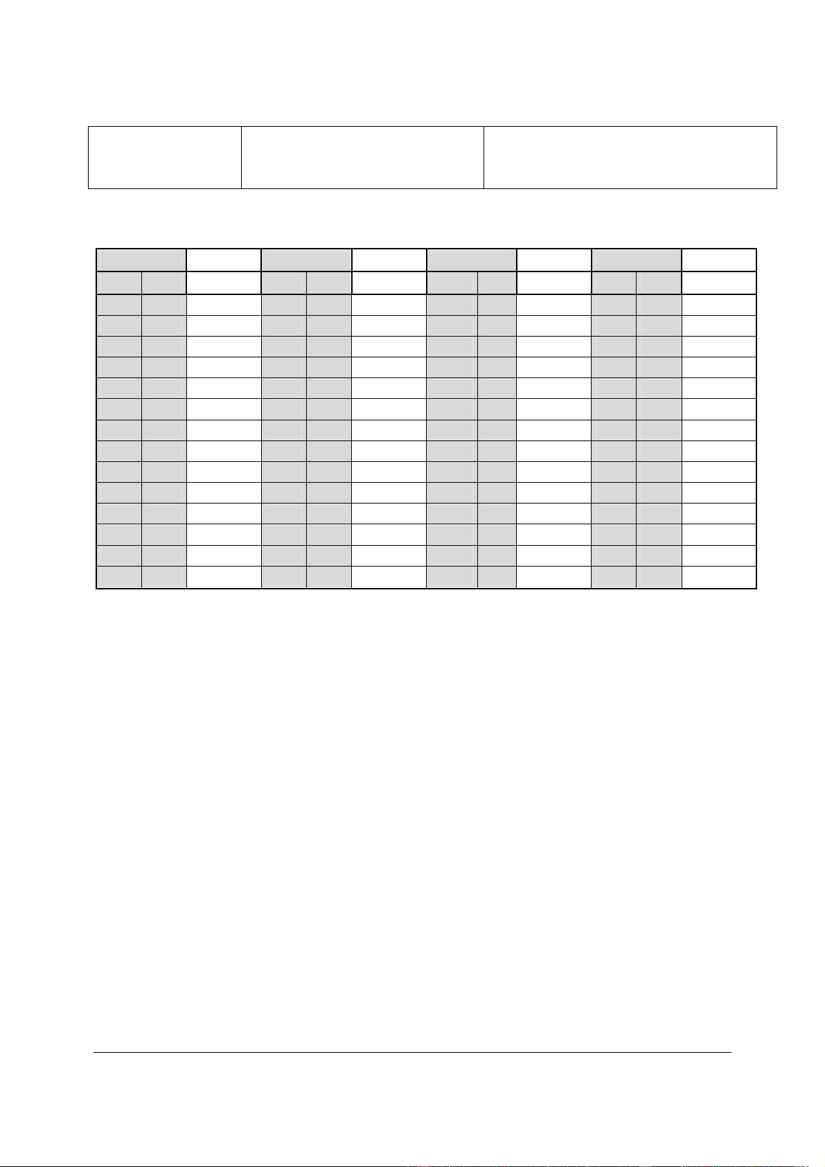
Table 4: Sensors resistance value vs real temperature.
Température
Résistance
Température
Résistance
Température
Résistance
Température
Résistance
°F °C Ω °F °C Ω °F °C Ω °F °C Ω
-50 -46 490,813 20 -7 46,218 90 32 7,334 160 71 1,689
-45 -43 405,71 25 -4 39,913 95 35 6,532 165 74 1,538
-40 -40 336,606 30 -1 34,558 100 38 5,826 170 77 1,403
-35 -37 280,279 35 2 29,996 105 41 5,21 175 79 1,281
-30 -34 234,196 40 4 26,099 110 43 4,665 180 82 1,172
-25 -32 196,358 45 7 22,763 115 46 4,184 185 85 1,073
-20 -29 165,18 50 10 19,9 120 49 3,76 190 88 983
-15 -26 139,402 55 13 17,436 125 52 3,383 195 91 903
-10 -23 118,018 60 16 15,311 130 54 3,05 200 93 829
-5 -21 100,221 65 18 13,474 135 57 2,754 205 96 763
0 -18 85,362 70 21 11,883 140 60 2,49 210 99 703
5 -15 72,918 75 24 10,501 145 63 2,255 215 102 648
10 -12 62,465 80 27 9,299 150 66 2,045 220 104 598
15 -9 53,658 85 29 8,25 155 68 1,857 225 107 553

MINI ULTRA ELECTRIC BOILERS Installation and operating manual (Revision: May 2015)
22
MINI ULTRA LIMITED WARRANTY
Warranty Coverage on the tank.
Thermo 2000 Inc. hereby warrants that the MINI ULTRA tank on
normal use and service will not leak for a period of fifteen (15)
years from the date of purchase. The warranty is valid as long as
the original residential purchaser owns the building in which the
unit was originally installed. In the event that a leak should occur
within this limited warranty period due to defective material or
workmanship, such leak having been verified by an authorized
company representative, Thermo 2000 inc. will repair or replace at
our sole discretion the failed unit with the nearest comparable
model at the time of replacement.
The original residential purchaser is responsible for all costs
associated with the removal and reinstallation, shipping and
handling to and from the manufacturing plant. The replacement
unit will be warranted for the remaining portion of the original
Warranty.
Warranty coverage on parts
All MINI ULTRA components & parts are warranted for a period of
two (2) years against defects due to defective material or
workmanship. The original purchaser is responsible for all costs
associated with the removal and reinstallation, shipping and
handling to and from the Manufacturer. The components,
repaired or replaced are warranted for the residual period of the
initial warranty on the parts.
Exclusions
This warranty is void and shall not apply if:
A) Defects or malfunctions resulting from installation,
repair, maintenance and/or usage that are not done in
conformity with the manufacturer’s installation manual.
B) Defects or malfunctions resulting from installation,
maintenance, or repair that are not done in accordance
with regulations in force.
C) Defects or malfunctions resulting from improper
installation, maintenance or repair done carelessly or
resulting from consumer damage (improper
maintenance, misuse, abuse, accident or alteration).
D) Installation in which a relief valve (pressure) is not
installed or if it is not functioning properly, or when it is
not connected to a drain to avoid damage to the
property.
E) Installation in which liquid circulating in the tank does
not remain in closed circuit or installation in which
piping is leaking or on systems with polybutylene pipes
or other having no oxygen absorption barrier.
F) Installation where the acidity of water is not within the
normal Environmental Protection Agency (EPA)
(between pH 6.5 – 8.5) guidelines or the domestic
water contains abnormal levels of particles matter or
water exceeding 10.5 gpg.
G) The MINI ULTRA unit has been subjected to non-
authorized modifications.
H) Defects or malfunction resulting from storing or
handling done elsewhere than Thermo 2000’s
manufacturing plant.
I) Units on which the serial number is removed or
obliterated.
Limitations
Thermo 2000 Inc. shall not be responsible for any damage, loss,
and inconvenience of any nature whatsoever, directly or indirectly,
relating to the breakdown or malfunction of the unit. This warranty
limits its beneficiary’s rights. Nevertheless, the beneficiary may
have other rights, which vary from jurisdiction to jurisdiction.
This warranty replaces any other expressed or implicit warranty
and constitutes the sole obligation of Thermo 2000 Inc. towards
the consumer. The warranty does not cover cost of removal,
reinstallation or shipping to repair or replace the unit, nor
administration fees incurred by the original consumer purchaser.
Thermo 2000 Inc. reserves its rights to make changes in the
design, construction, or material, as in its judgment constitute an
improvement of former practices.
This warranty is valid only for installations made within the
territorial limits of Canada and the United States.
Warranty service procedure
Only authorized MINI ULTRA dealers are permitted to perform
warranty obligations. The owner or his contractor must provide
Thermo 2000’s head office or authorized depot with the defective
unit together with the following information: MINI ULTRA model
and serial number, copy of the original sales receipt and owner’s
identification certificate
.
THERMO 2OOO INC.
500, 9
th
Avenue, Richmond (Qc) Canada J0B 2H0
Tel: (819) 826-5613 Fax: (819) 826-6370
www.thermo2000.com