SPECIFICATIONS
POWER SUPPLY
REQUIREMENTS 120 V, 60 Hz
MOTOR Single Phase, Dielectric Oil Filled
HORSEPOWER
1/2 HP............ Sewage
(RPP50, SEL50, WCS50T)
Efuent
(EFL50)
CIRCUIT REQUIREMENTS 15 A (minimum)
DIMENSIONS
14 in. high x 12 in. base
(RPP50)
13-1/2 in. high x 11 in. base
(SEL50, EFL50)
16-5/8 in. high x 9-5/8 in. base
(WCS50T)
ON LEVEL (FACTORY SET)
Approximately 16. in.
(RPP50)
Approximately 17 in.
(SEL50, EFL50)
Approximately 19 in.
(WCS50T)
OFF LEVEL (FACTORY SET) Approximately 7.5 in.
(RPP50)
Approximately 7 in.
(SEL50, EFL50)
Approximately 10.5 in.
(WCS50T)
610001W-001 E 1/20
CONSTRUCTION
MOTOR HOUSING
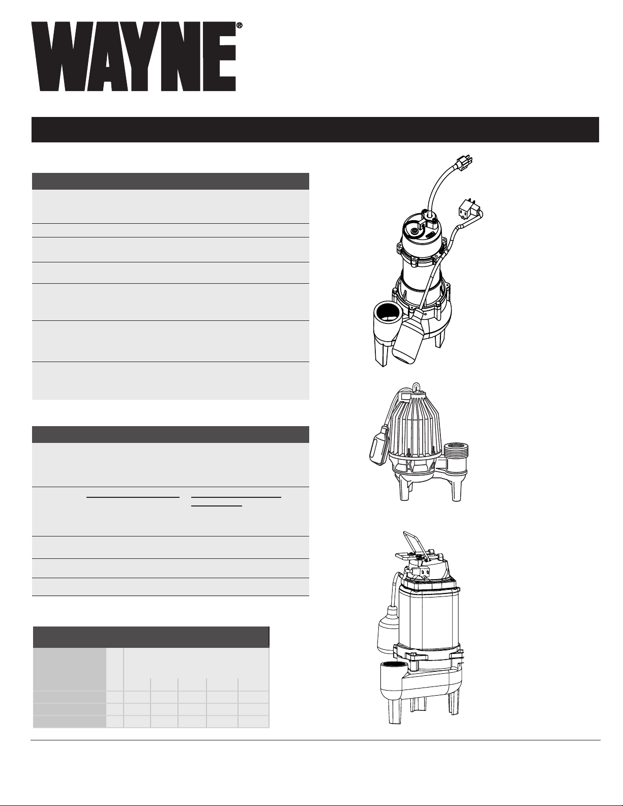
Cast Iron (RPP50, WCS50T)
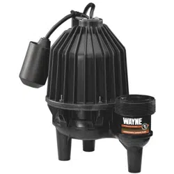
Reinforced Thermoplastic (SEL50, EFL50)
VOLUTE
Cast Iron (RPP50, WCS50T)
Cast Iron
Reinforced Thermoplastic
(SEL50, EFL50)
Glass Reinforced Thermoplastic
IMPELLER Glass Reinforced Thermoplastic
SHAFT Steel
DISCHARGE 2 in. NPT
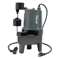
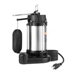
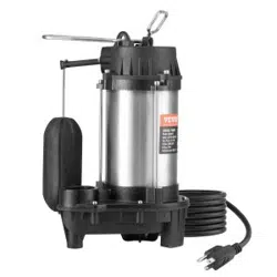
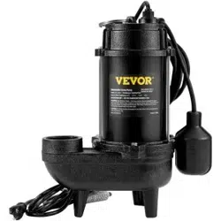
Sewage/Effluent Pumps
Intended for Indoor Use Only
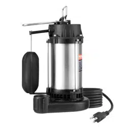
RPP50
Sewage- SEL50
Efuent- EFL50
WCS50T
Operating Instructions and Parts Manual Sewage/Effluent
Please read and save these instructions. Read carefully before attempting to assemble, install,
operate or maintain the product described. Protect yourself and others by observing all safety
information. Failure to comply with instructions could result in personal injury and/or property
damage! Retain instructions for future reference.
© 2018, WAYNE/Scott Fetzer Company.
www.waynepumps.com
PERFORMANCE GAL/HR
Model HP
Discharge Head (Lift Distance)
0 ft 5 ft 10 ft 15 ft 20 ft
RPP50 1/2 6200 4800 3240 1500 -
SEL50 1/2 10000 9000 7200 5000 2000
WCS50T 1/2 10000 9600 8000 3300 -
EFL50 1/2 10000 9000 7200 5000 2000
INSTALLATION MANUAL
2
SAFETY SIGNAL WORDS
This manual contains information that is very important
to know and understand. This information is provided for
SAFETY and to PREVENT EQUIPMENT PROBLEMS. To
help recognize this information, observe all safety information
labeled danger, warning, caution, and notice.
SEWAGE/EFFLUENT PUMP
DESCRIPTION
Sewage pumps are pumps used to remove waste water that
contains solids up to 2 inches in diameter. The most common
application is for draining bathroom waste water to a sewer or
septic line.
Effluent pumps are pumps used to remove gray water from
septic tanks, sump pits, or laundry tray systems. Gray water is
waste water from bathtubs, sinks, washing machines, and other
kitchen appliances.
Intended for indoor use only. Installation of this pump outdoors,
unprotected from the weather, may cause hazardous conditions
and will void warranty. If using outdoors, protect pump from
direct weather elements such as sun, rain, sleet, snow, and
extreme temperature changes. Water inside the pump may
freeze, limiting its performance and damaging the pump and
pipes.
Intended for Indoor Use Only
PLEASE SEE WWW.WAYNEPUMPS.COM FOR PRODUCT INFORMATION AND INSTALLATION VIDEOS
MAKE SURE THERE IS A PROPERLY GROUNDED RECEPTACLE
AVAILABLE. This pump is supplied with a grounding conductor
and grounding-type attachment plug. To reduce the risk of electric
shock, be certain that it is connected only to a properly grounded,
grounding-type receptacle.
S’ASSURER QU’UNE PRISE DE MISE À LA TERRE EST DISPONIBLE.
Cette pompe est fournie avec un conducteur et une fiche de mise à
la terre. Pour réduire le risque de choc électrique, s’assurer qu’elle
est branchée seulement à une prise de courant correctement mise
à la terre.
FOR ADDED SAFETY the receptacle must be protected with a ground
fault circuit interrupter (GFCI). All wiring must be performed by a
qualified licensed electrician and comply with the National Electric
Code and all applicable local codes and ordinances.
POUR PLUS DE SÉCURITÉ, la prise de courant doit être protégée par
un disjoncteur de fuite à la terre. Tout le câblage doit être effectué
par un électricien qualifié et être conforme au Code électrique
national et à tous les codes et règlements locaux applicables.
NEVER REMOVE THE GROUND PRONG from the plug or bypass the
grounding wires.
NE JAMAIS RETIRER LE CONNECTEUR DE MISE À LA TERRE de la prise
ou contourner les fils de mise à la terre.
MAKE SURE THE POWER SUPPLY HAS A FUSE OR CIRCUIT BREAKER
rated to handle the current (amps) noted on the pump nameplate
or cord tag.
S’ASSURER QUE L’ALIMENTATION ÉLECTRIQUE EST MUNIE D’UN
FUSIBLE OU D’UN DISJONCTEUR d’une valeur nominale appropriée
pour supporter l’intensité du courant (ampérage) indiquée sur la
plaque signalétique ou l’étiquette du cordon de la pompe.
IMPORTANT SAFETY INFORMATION
CONSIGNES DE SÉCURITÉ
IMPORTANTES
WARNING INDICATES A POTENTIALLY HAZARDOUS SITUATION
WHICH, IF NOT AVOIDED, COULD RESULT IN DEATH OR
SERIOUS INJURY.
LA MENTION AVERTISSEMENT INDIQUE UNE SITUATION
POTENTIELLEMENT DANGEREUSE QUI, SI ELLE N’EST PAS
ÉVITÉE, RISQUE D’ENTRAÎNER DES LÉSIONS CORPORELLES
GRAVES OU MÊME LA MORT.
RISK OF ELECTRIC SHOCK. TO REDUCE THIS RISK,
OBSERVE THE FOLLOWING WARNINGS:
RISQUE DE CHOC ÉLECTRIQUE. POUR RÉDUIRE CE
RISQUE, TENIR COMPTE DES AVERTISSEMENTS
SUIVANTS
UNPACKING
Inspect this unit before it is used. Occasionally, products
are damaged during shipment. If the pump or components
are damaged, return the unit to the place of purchase for
replacement, or call Customer Support (800-237-0987).
INSTALLATION MANUAL
3
ALWAYS DISCONNECT THE PUMP from power supply before installing,
servicing or making any adjustments.
TOUJOURS METTRE LA POMPE HORS TENSION avant de procéder à
l’installation, à l’entretien ou à des réglages.
DO NOT WALK on the floor when water is present until all power is
turned off. If the electric panel is in the basement, call an electrician.
NE PAS MARCHER sur un sol mouillé avant que l’alimentation
générale ne soit coupée. Si le tableau électrique est en sous-sol,
appeler un électricien.
NEVER HANDLE A PUMP or motor with wet hands or when standing
on a wet or damp floor while the pump is plugged into the power
supply.
NE JAMAIS MANIPULER UNE POMPE ou un moteur de pompe avec
les mains mouillées ou debout dans l’eau ou sur une surface
humide.
RISK OF ELECTRIC SHOCK. This pump has not been investigated for
use in swimming pool and marine areas.
RISQUE DE CHOC ÉLECTRIQUE. Cette pompe n’a pas fait l’objet
de vérification pour une utilisation dans les piscines et les aires
marines.
DO NOT USE TO PUMP FLAMMABLE OR EXPLOSIVE FLUIDS such as
gasoline, fuel oil, kerosene, etc. Do not use in a flammable and/or
explosive atmosphere. Pump should only be used to pump clear
water. Personal injury and/or property damage will result and void
warranty.
NE PAS UTILISER POUR POMPER DES FLUIDES INFLAMMABLES OU
EXPLOSIFS tels que l’essence, le mazout, le kérosène, etc. Ne
pas utiliser dans un environnement inflammable et/ou explosif.
La pompe ne doit être utilisée que pour pomper de l’eau claire.
Des blessures corporelles et/ou des dégâts matériels pourraient
en résulter.
PUMPS ARE NOT DESIGNED TO TRANSFER WATER INTENDED FOR
DRINKING. Do not use the pump for moving water that will be
used for potable/drinking water. Pump should only be used in
applications for which it is designed.
LES POMPES NE SONT PAS CONÇUES POUR L’ACHEMINEMENT
D’EAU DESTINÉE À LA CONSOMMATION. Ne pas utiliser la pompe
pour transporter de l’eau qui sera utilisée comme de l’eau
potable/destinée à la consommation. La pompe doit être utilisée
uniquement dans les applications pour lesquelles elle est conçue.
DO NOT USE AN EXTENSION CORD OR SURGE PROTECTOR. Extension
cords and/or surge protectors could present a safety hazard if not
sized properly, become damaged or the connection falls into the
sump. If receptacle is not within reach of the pump’s power cord,
contact a qualified licensed electrician to install a new receptacle.
NE PAS UTILISER DE RALLONGE NI DE PROTECTEUR DE SURTENSION.
Les rallonges et/ou les protecteurs de surtension peuvent présenter
un danger pour la sécurité s’ils ne sont pas correctement calibrés,
s’ils sont endommagés ou si le raccordement tombe dans le
puisard. Si la prise n’est pas à portée du cordon d’alimentation
de la pompe, contacter un électricien qualifié pour installer une
nouvelle prise.
CAUTION INDICATES A POTENTIALLY HAZARDOUS SITUATION
WHICH, IF NOT AVOIDED, MAY RESULT IN MINOR OR
MODERATE INJURY.
MISE EN GARDE
LA MENTION MISE EN GARDE INDIQUE UNE SITUATION
POTENTIELLEMENT DANGEREUSE QUI, SI ELLE N’EST PAS
ÉVITÉE, POURRAIT ENTRAÎNER DES BLESSURES MINEURES
OU MODÉRÉES.
TO REDUCE THE RISK OF HAZARDS THAT CAN CAUSE
INJURY OR PROPERTY DAMAGE, OBSERVE THE FOLLOWING
WARNINGS:
POUR RÉDUIRE LE RISQUE DE DANGERS POUVANT CAUSER
DES BLESSURES OU DES DÉGÂTS MATÉRIELS, RESPECTER
LES MISES EN GARDE SUIVANTES :
IT IS THE INSTALLER’S RESPONSIBILITY TO MAKE SURE THE
PUMPS AUTOMATIC SWITCH IS ABLE TO OPERATE WITHOUT ANY
OBSTRUCTIONS WITHIN THE BASIN. It is recommended that the
installer test and observe the pump’s operation for several cycles
after installation.
IL EST DE LA RESPONSABILITÉ DE L’INSTALLATEUR DE S’ASSURER QUE
L’INTERRUPTEUR AUTOMATIQUE DE POMPE PEUT FONCTIONNER SANS
AUCUN BLOCAGE À L’INTÉRIEUR DU SYSTÈME. Il est recommandé
que l’installateur teste et observe le fonctionnement de la pompe
pendant plusieurs cycles après l’installation.
INSTALLATION MANUAL
4
IT IS REQUIRED TO USE RIGID PIPING AND FITTINGS to secure the
pump in the basin and reduce pump movement. Pump movement
can prevent the switch from operating correctly. Do not use flexible
hosing.
IL EST NÉCESSAIRE D’UTILISER DES TUYAUX ET DES RACCORDS
RIGIDES pour fixer la pompe dans le système et réduire les
mouvements de la pompe. Les mouvements de la pompe peuvent
empêcher l’interrupteur de fonctionner correctement. Ne pas
utiliser de tuyaux flexibles.
IT IS REQUIRED TO USE A CHECK VALVE with this pump to prevent the
back-flow of water after each pump cycle.
Cette pompe NÉCESSITE L’UTILISATION D’UNE VANNE DE CONTRÔLE
pour empêcher le reflux d’eau souterraine claire après chaque
cycle de pompage.
DO NOT INSTALL OR OPERATE THE PUMP IF IT HAS BEEN DAMAGED
IN ANY WAY.
NE PAS INSTALLER OU FAIRE FONCTIONNER LA POMPE SI ELLE A ÉTÉ
ENDOMMAGÉE DE QUELQUE MANIÈRE QUE CE SOIT.
DO NOT LIFT OR CARRY THE PUMP BY THE POWER CORD. Use the
pump’s handle or lift ring.
NE PAS SOULEVER OU PORTER LA POMPE PAR LE CORDON
D’ALIMENTATION. Utiliser la poignée ou la bague de levage de la
pompe.
AN INDEPENDENT HIGH WATER ALARM OR BACK UP PUMP SHOULD BE
USED when risk of property damage from high water levels exists.
UNE ALARME AUTONOME DE? NIVEAU D’EAU ÉLEVÉ OU UNE POMPE DE
SAUVEGARDE DOIVENT ÊTRE UTILISÉES en cas de risque de dégâts
matériels causés par des niveaux d’eau élevés.
REPLACE THE TETHER SWTICH EVERY TWO (2) YEARS. This required
maintenance will reduce the risk of improper pump operation,
switch failure and/or flooding.
REMPLACER LE COMMUTATEUR TOUS LES DEUX (2) ANS. Cet entretien
réduira le risque d’utilisation incorrecte de la pompe, de défaillance
de l’interrupteur ou d’inondation.
This product can expose you to chemicals, including DEHP,
which is known to the State of California to cause cancer, birth
defects and reproductive harm. For more information, go to
www.P65Warnings.ca.gov.
Ce produit peut vous exposer à des produits chimiques,
notamment du DOP, reconnus par l’État de Californie comme
étant cancérigènes et à l’origine d’anomalies congénitales et de
problèmes de l’appareil reproductif. Pour plus de renseignements,
visiter le site www.P65Warnings.ca.gov.
TETHER FLOAT SWTICH This float is not adjustable. By adjusting the
tether switch it can affect the specifications of the application of the
pump and can change the life expectancy of the unit.
L’INTERRUPTEUR DU FLOTTEUR À AMARRE est réglable. L’ajuster
peut affecter les spécifications d’utilisation de la pompe et peut en
modifier la durée de vie.
INSTALLATION MANUAL
5
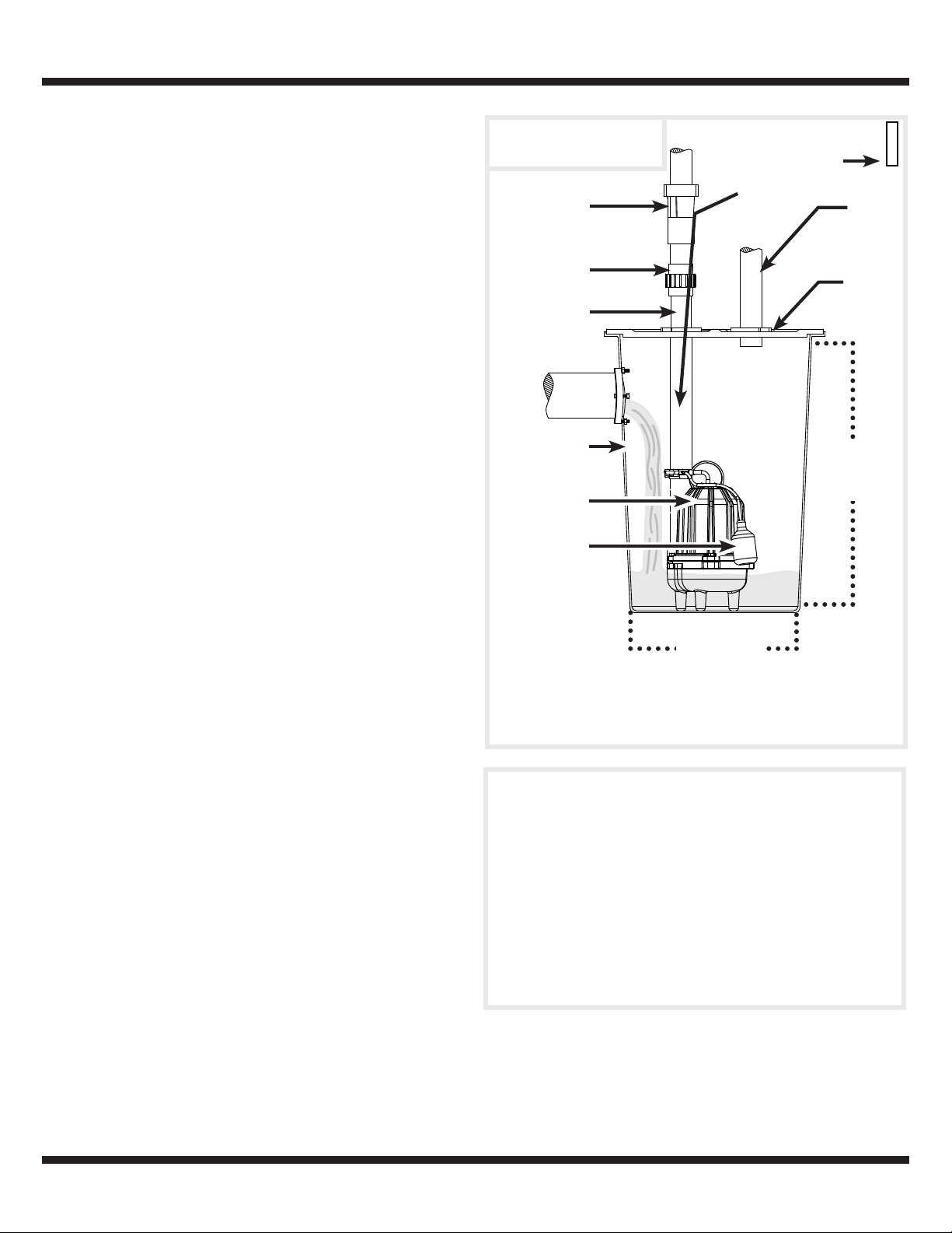
ON LEVEL
(RPP50-APPROX. 16 IN.
SEL50-APPROX. 17 IN.
WCS50T-APPROX. 19 IN.)
OFF LEVEL
(RPP50-APPROX. 7.5 IN.
SEL50-APPROX. 7 IN.
WCS50T-APPROX. 10.5 IN.)
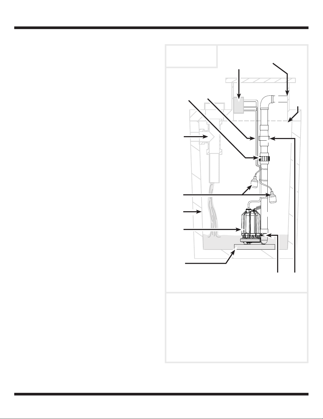
Submersible Sewage
Pumps
1
3
5
2
7
6
4
8
9
10
11
1. Check Valve 7. Tether Switch
2. Union 8. Power Supply Cord
3. Discharge Pipe 9. GFCI Outlet
4. Inlet Pipe 10. Gasket/Basin Lid
5. Basin 11. Vent Pipe
6. Pump
MINIMUM
BASIN
DIAMETER
(18 IN.)
TYPICAL SEWAGE INSTALLATION
1. This installation must be in accordance with the National
Electric Code and all applicable local codes and
ordinances.
2. Use a basin (5) that is large enough to accommodate the
pump. The basin diameter should be a minimum of 18
inches and the depth a minimum of 24 inches.
3. Clean the basin of all debris.
4. Set the pump (6) on a solid, level surface. Do not place
pump directly on clay, earth, gravel, or sand. A brick or
block may be installed under the pump to provide a solid
base.
5. Position pump (6) in the basin (5) so the tether switch (7) is
away from incoming water. Verify the tether float switch has
at least 1 inch clearance to the side wall of the basin and is
free of any possible obstructions.
6. Install discharge plumbing according to local, regional and
state codes. Do not reduce the discharge pipe (3) size
below that which is provided on the pump (6).
7. A union (2) should be installed above the basin to allow
easy removal of the pump (6) for cleaning and service.
8. Install a check valve (1) (required) to prevent back-flow.
It should be installed above the union.
9. A gate valve or ball valve should be installed above the
check valve if required by local, regional or state codes.
10. Connect remaining discharge pipe. Keep sections as short
as possible with a minimum number of turns.
11. A vent pipe (11) is required. It removes gases and odors
and should be installed as required by local, regional or
state codes.
12. Secure power supply cord (8) to discharge pipe (3) using
cable or zip ties to prevent possible switch entanglement.
13. Connect tether switch (7) piggyback cord to a ground fault
circuit interrupter (GFCI) outlet (9) (required) then connect
the pump power supply cord (8) into the piggyback cord.
14. Fill the basin with water. The pump will start when the
water level has reached the switch-on level. Verify the
pump is operating normally.
15. Install a basin cover and gasket (10) to prevent debris from
falling into the basin, prevent personal injury, and to contain
gases and odors.
MINIMUM
BASIN
DEPTH
(24 IN.)
INSTALLATION MANUAL
6
Effluent Pump in
Septic Tank
1. This installation must be in accordance with the National
Electric Code and all applicable local codes and ordinances.
2. Clean the basin of all debris.
3. Set the pump on a solid, level surface. Do not place pump
directly on clay, earth, gravel, or sand. A brick or block may
be installed under the pump to provide a solid base.
4. Verify the float switch has at least 1 inch clearance to
the side wall of the basin and is free of any possible
obstructions.
5. If optional control device or float is used, follow mounting
instructions supplied with device or float.
6. Install discharge plumbing according to local, regional and
state codes. Do not reduce the discharge pipe size below
that which is provided on the pump.
7. Install a union to allow easy removal of the pump for
cleaning and service.
8. Install a check valve (required) to prevent back-flow. It
should be installed above the union.
9. A gate valve or ball valve should be installed above the
check valve as required by local, regional or state codes.
10. Connect remaining discharge pipe. The remainder of
the discharge line should be as short as possible with a
minimum number of turns.
11. Secure power supply cord to discharge pipe using cable or
zip ties to prevent possible switch entanglement.
12. Connect pump power supply cord to a ground fault circuit
interrupter (GFCI) receptacle.
13. Fill the basin with water. The pump will start when the water
level has reached the switch-on level. Verify the pump is
operating normally. If the discharge line is exposed to freezing
temperatures, the pipe must be positioned in a downward
slope away from the foundation so any remaining water will
drain away and not freeze.
14. Secure a basin/tank cover and gasket to the basin to prevent
debris from falling into the basin, prevent personal injury, and to
contain gases and/or odors.
TYPICAL EFFLUENT INSTALLATION
1. Discharge Outlet Pipe 7. Septic Tank/ Basin
2. Junction Box 8. Effluent Pump
3. Pump/Switch Wires 9. Brick or Block
4. Union 10. Discharge Pipe
5. Effluent Inlet Pipe 11. Check Valve
6. Switches 12. Tank Lid
1
12
3
4
6
9
2
10 11
8
7
5
INSTALLATION MANUAL
7
TROUBLESHOOTING
Symptoms Possible Cause(s) Suggested Remedies
Pump will not
start or run
1. Water level too low
2. Blown fuse or tripped circuit breaker
3. Low supply voltage
4. Motor
5. Switch
6. Inlet clogged
7. Switch obstruction
1. Water must be at the appropriate level to activate switch
2. If blown, determine cause and then either replace with proper
sized fuse or reset breaker
3. Contact an electrician
4. Replace pump
5. Replace tether switch
6. Remove debris
7. Remove obstruction to verify free motion of switch
Pump starts and
stops too often
1. Back-flow of water from discharge
pipe
2. Switch
3. Check valve not functioning properly
or leaking
1. Install check valve
2. Replace tether switch
3. Remove and examine check valve for prop er in stal la tion and free
operation. Replace check valve if necessary.
Pump shuts off
and turns on
independently
of switch (trips
thermal overload
protection)
1. Switch
2. Switch obstruction
3. Obstruction in discharge pipe
4. Low supply voltage
1. Replace tether switch
2. Remove obstruction to verify free motion of switch
3. Remove obstruction in discharge piping
4. Contact an electrician.
Pump trips GFCI
1. Bad GFCI
2. Bad pump
1. Contact an electrician to replace GFCI
2. Replace pump
TROUBLESHOOTING WARNINGS
ALWAYS DISCONNECT THE PUMP FROM POWER SUPPLY before
installing, servicing or making any adjustments.
TOUJOURS METTRE LA POMPE HORS TENSION avant de procéder à
l’installation, à l’entretien ou à des réglages.
LET PUMP COOL FOR A MINIMUM OF 2 HOURS BEFORE ATTEMPTING TO
SERVICE. Submersible pumps contain oil that become pressurized
and hot under normal operating conditions.
LAISSER REFROIDIR LA POMPE PENDANT AU MOINS 2 HEURES AVANT
D’ESSAYER DE LA RÉPARER. Les pompes submersibles contiennent
de l’huile qui devient pressurisée et chaude dans des conditions
normales de fonctionnement.
1. Submersible pump models have permanently lubricated
bearings and require no additional lubrication.
2. Submersible pumps contain dielectric oil for cooling.
Dielectric oil can be harmful to the environment. Follow state
environmental laws when disposing of pump.
3. The pump motor is equipped with automatic resetting
thermal protector and may restart unexpectedly. Protector
tripping is an indication of motor overloading as a result of
operating the pump at low heads, excessively high or low
voltage, inadequate wiring, incorrect motor conditions, or at
the end of product life.

INSTALLATION MANUAL
8
TROUBLESHOOTING (CONTINUED)
Symptoms Possible Cause(s) Suggested Remedies
Pump operates
noisily or vibrates
excessively
1. Worn bearings
2. Impeller broken
3. Piping attachments to building
structure too rigid or too loose
1. Replace pump
2. Replace pump
3. Install rubber coupling (available at local hardware stores) to isolate
pump vibration from discharge plumbing
Pump will not
shut off
1. Switch
2. Switch obstructions
3. Restricted discharge (obstruction in
piping)
4. Excessive inflow or pump not
properly sized for application
1. Replace tether switch
2. Remove obstruction to verify free motion of switch
3. Remove obstruction from discharge piping
4. Recheck all sizing calculations to determine proper pump size
Pump operates
but delivers little
or no water
1. Low supply voltage
2. Inlet clogged
3. Broken impeller
4. Pump not properly sized for
application
5. Check valve stuck closed or
installed backwards
6. Shut off valve closed
1. Contact an electrician
2. Remove debris
3. Replace pump
4. Recheck all sizing calculations to determine proper pump size
5. Remove and examine check valve for proper installation and free
operation
6. Open valve
ROUTINE MAINTENANCE
The pump should be inspected 3-4 times per year for pump movement or buildup of debris on the switch or float. Reposition
pump if it has moved. Remove any debris that could interfere with the operation of the switch. Lack of proper routine maintenance
will void warranty.
• Make sure the pump is plugged in to a working ground fault circuit interrupter (GFCI) outlet and the cord is in good shape. In
damp areas, GFCI breakers may trip, effectively shutting off the effluent pump. Check in on your sewage pump and reset the
GFCI if necessary.
• Ensure the pump is standing upright. Vibrations during operation can cause it to fall or tilt onto one side. This can jam the float
so it can’t activate the pump.
• Pour a bucket of water into the pit to make sure the pump starts automatically and the water drains quickly once the pump is
on. If the pump doesn’t start, have it serviced or replaced.
• Replace the tether switch every two (2) years. This maintenance will reduce the risk of improper pump operation, switch failure
and/or flooding.
WARRANTY & SERVICE PARTS SHEET - REPLACEMENT PARTS
9
2
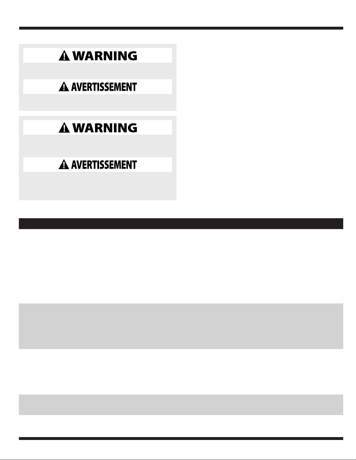
REPAIR KITS
REF. NO. DESCRIPTION PART NUMBER
1 TETHER SWITCH 56835-WYN1
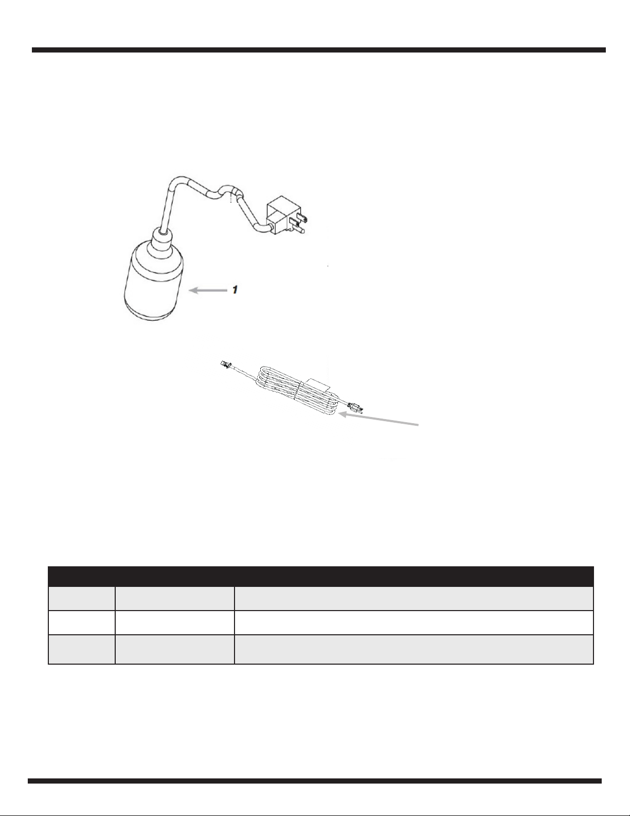
2
10 FT. POWER CORD
(WCS50T)
31006-WYN2

www.waynepumps.com
10
FOR REPLACEMENT
PARTS OR CUSTOMER SUPPORT,
CALL 1-800-237-0987
Please provide following information:
- Model number
- Serial number on cord tag (not to be removed)
- Part description and number as shown in parts list
LIMITED WARRANTY
For one year for RPP50, SEL50, and EFL50 models, and three years for WCS50T model from the date of purchase, from an authorized dealer, Wayne Water Systems
will repair or replace, at its option for the original purchaser, any part or parts of its Sewage or Effluent Pumps or Water Pumps (“Product”) found upon examination
by Wayne Water Systems to be defective in materials or workmanship. Please call Wayne Water Systems (800-237-0987) for warranty instructions. Be prepared to
provide the model number and the serial number when exercising this warranty. All transportation charges on Products or parts submitted for repair or replacement
must be paid by purchaser. This Limited Warranty is not transferrable. This Limited Warranty does not cover Products which have been damaged as a result of
accident, abuse, misuse, neglect, improper installation, improper maintenance, or failure to operate in accordance with WAYNE’s written instructions.
This Limited Warranty does not cover Products which have been damaged as a result of accident, abuse, misuse, neglect, improper installation, improper
maintenance, or failure to operate in accordance with Wayne Water Systems’ written instructions.
THIS WARRANTY IS IN LIEU OF ANY AND ALL OTHER WARRANTIES, OBLIGATIONS OR AGREEMENTS, EXPRESSED OR IMPLIED, INCLUDING ANY IMPLIED
WARRANTY OF MERCHANTABILITY OR FITNESS FOR ANY PARTICULAR PURPOSE, AND ANY RIGHTS OR REMEDIES AGAINST ANY PERSON OR ENTITY UNDER THE
UNIFORM COMMERCIAL CODE OR OTHERWISE WITH RESPECT TO THE SALE OF THE PRODUCT. THE REMEDIES AND OBLIGATIONS STATED IN THIS WARRANTY
ARE THE SOLE AND EXCLUSIVE REMEDIES OF AND OBLIGATIONS TO THE OWNER FOR ANY AND ALL MATTERS ARISING WITH RESPECT TO OR IN ANY WAY
CONNECTED WITH THE PRODUCT, REGARDLESS OF THE SOURCE OR PROVIDER OF SUCH GOODS. IN NO EVENT, WHETHER AS A RESULT OF BREACH OF CONTRACT,
WARRANTY TORT (INCLUDING NEGLIGENCE) OR OTHERWISE, SHALL WAYNE WATER SYSTEMS OR ANY AFFILIATE BE LIABLE FOR ANY SPECIAL, INCIDENTAL OR
CONSEQUENTIAL DAMAGES.
You MUST retain your purchase receipt along with this form. In the event you need to exercise a warranty claim, you MUST send a copy of the purchase receipt along
with the material or correspondence. Please call Wayne Water Systems (800-237-0987) for return authorization and instructions.
DO NOT MAIL THIS FORM TO Wayne Water Systems. Use this form only to maintain your records.
MODEL NO._____________________ SERIAL NO._________________________ INSTALLATION DATE __________________________
ATTACH YOUR RECEIPT HERE
ADDRESS PARTS CORRESPONDENCE TO:
WAYNE Water Systems
101 Production Drive
Harrison, OH 45030 U.S.A.
INSTALLATION MANUAL
Thank you for making Wayne Water Systems a key part of your
home maintenance program. If properly installed, maintained
and operated in accordance with Wayne Water Systems’ written
instructions, your pump should provide you with approximately
( * ) years of service.
Product Warranty ( * ) Expected Life
1 3
2 3
3 6
5 6

www.waynepumps.com
11
NOTES

www.waynepumps.com
12