Loading ...
Loading ...
Loading ...
www.dimplex.de 452234.66.02 · FD 9311 EN7
English
SI 50TE - SI 130TE
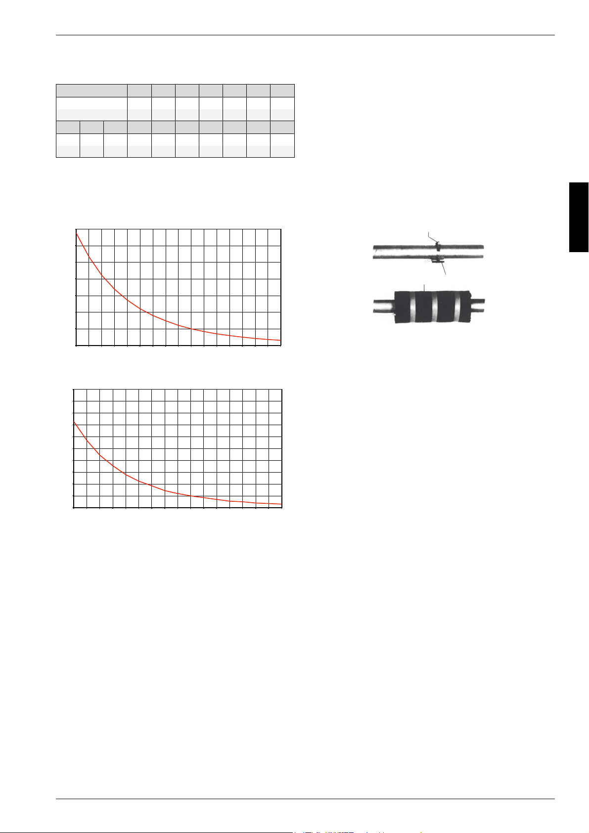
7.4.1 Sensor characteristic curves
The temperature sensors to be connected to the heat pump
manager must correspond to the sensor characteristic curve
illustrated in Fig.7.1. The only exception is the external
temperature sensor included in the scope of supply of the heat
pump (see Fig.7.2)
Fig. 7.1:Sensor characteristic curve NTC-10
Fig. 7.2:Sensor characteristic curve, NTC-2 according to
DIN 44574 External temperature sensor
7.4.2 Mounting the external temperature
sensor
The temperature sensor must be mounted in such a way that all
weather conditions are taken into consideration and the
measured value is not falsified.
On the external wall of a heated room used as living space,
if possible on the north or north-west side of the building
Do not install in a “sheltered position” (e.g. in a wall niche or
under a balcony)
Not in the vicinity of windows, doors, exhaust air vents,
external lighting or heat pumps
Not to be exposed to direct sunlight at any time of year
Sensor lead: Max. length 40 m; min. core cross-section
0.75 mm²; external diameter of the cable 4-8 mm.
7.4.3 Installing the strap-on sensor
It is only necessary to mount the strap-on sensors if they are
included in the scope of supply of the heat pump but have not yet
been installed.
The strap-on sensors can be fitted as pipe-mounted sensors or
installed in the immersion sleeve of the compact manifold.
Mounting as a pipe-mounted sensor
Remove paint, rust and scale from heating pipe.
Coat the cleaned surface with heat transfer compound
(apply sparingly).
Attach the sensor with a hose clip (tighten firmly, as loose
sensors can cause malfunctions) and thermally insulate.
7.4.4 Hydraulic distribution system
The compact manifold and the dual differential pressureless
manifold function as an interface between the heat pump, the
heating distribution system, the buffer tank and, in some cases,
even the hot water cylinder. A compact system is used to simplify
the installation process, so that a lot of different components do
not have to be installed individually. Further information can be
found in the relevant installation instructions.
Compact manifold
The return sensor can remain in the heat pump, or should be
installed in the immersion sleeve. The remaining empty space
between the sensor and the immersion sleeve must be filled
completely with heat transfer compound.
dual differential pressureless manifold
In order for the heating circuit pumps of the generator and con-
sumer circuits to supply the flow to the return sensor, this must
be installed in the immersion sleeve of the dual differential pres-
sureless manifold.
Temperature in °C
-20 -15 -10 -5 0 5 10
NTC-2 in k 14.6 11.4 8.9 7.1 5.6 4.5 3.7
NTC-10 in k 67.7 53.4 42.3 33.9 27.3 22.1 18.0
15 20 25 30 35 40 45 50 55 60
2.92.42.01.71.41.11.00.80.70.6
14.9 12.1 10.0 8.4 7.0 5.9 5.0 4.2 3.6 3.1
([WHUQDOWHPSHUDWXUHLQ>&@
5HVLVWDQFHYDOXHLQ>N2KP@
([WHUQDOWHPSHUDWXUHLQ>&@
5HVLVWDQFHYDOXHLQ>N2KP@
+RVHFOLS
6WUDSRQVHQVRU
7KHUPDOLQVXODWLRQ
Loading ...
Loading ...
Loading ...