Loading ...
Loading ...
Loading ...

10 English
ble malfunctions on your appliance within the warranty
period free of cost, provided that a material or manufac-
turing defect is the cause. In a warranty case, please
contact your dealer (with the purchase receipt) or the
next authorised customer service site.
(See overleaf for the address)
Safety devices
몇 CAUTION
Missing or modified safety devices
Safety devices are provided for your own protection.
Never modify or bypass safety devices.
Symbols on the appliance
(according to type of appliance)
Pressure controller
The pressure controller keeps the pressure in the steam
boiler as constant as possible during operation. The
heating is switched off when the maximum operating
pressure is reached in the steam boiler and is activated
if there is a pressure drop in the steam boiler as a result
of a steam removal.
Safety lock
The safety lock seals the steam boiler from the steam
pressure present. If the pressure regulator is defective
and overpressure occurs in the steam boiler, an pres-
sure relief valve opens in the safety lock and steam
leaks out through the lock.
Prior to restarting the appliance, contact the responsible
KÄRCHER Customer Service.
Safety thermostat
The safety thermostat prevents the device from over-
heating. If the pressure controller fails and the device
overheats, then the safety thermostat switches the de-
vice off.
To reset the safety thermostat, contact the responsible
KÄRCHER Customer Service.
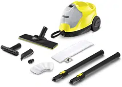
Description of the unit
The maximum amount of equipment is described in
these operating instructions. Depending on the model
used, there are differences in the scope of delivery (see
packaging).
For the figures, please refer to the graphics page.
Illustration A
1 Indicator light (green) - grid voltage present
2 Indicator light (orange) - heating
3 Safety lock
4 Holder for accessories
5 Park bracket for floor nozzle
6 Mains connection cable with mains plug
7 Non-driven wheels
8 Steering roller
9 Steam gun
10 Unlocking button
11 Selector switch for steam volume (with child lock)
12 Steam lever
13 Steam hose
14 Spotlight nozzle
15 Round brush (black)
16 **Power nozzle
17 **Round brush (large)
18 Manual nozzle
19 Manual nozzle microfibre cover
20 Extension tubes (2 x)
21 Unlocking button
22 Floor nozzle
23 Hook and eye connection
24 Microfibre floor cloth (1 x)
25 **Microfibre floor cloth (2 x)
** SC 2 EasyFix Premium
Installation
Installing accessories
1. Insert and engage the steering roller and non-driven
wheels.
Illustration B
2. Push the open end of the accessory onto the steam
gun so that the unlocking button on the steam gun
engages.
Illustration H
3. Push the open end of the accessory onto the spot-
light nozzle.
Illustration I
4. Connect the extension tubes with the steam gun.
a Push the first extension tube onto the steam gun
so that the unlocking button on the steam gun en-
gages.
The connection pipe is connected.
b Push the second extension tube onto the
first extension tube.
The connection pipes are connected.
Illustration J
5. Push the accessory and / or the floor nozzle onto the
free end of the extension tube.
Illustration K
The accessory is connected.
Disconnecting accessories
1. Push the unlocking button and pull the parts apart.
Illustration M
Operation
Filling water
Note
Warm water reduces the heating-up time.
Note
Descaling the steam boiler is not required if commer-
cially available distilled water is used.
1. Unscrew the safety lock.
Illustration C
Risk of burns, surface of appliance be-
comes hot during operation
Risk of scalding from steam
Read operating instructions
Loading ...
Loading ...
Loading ...
