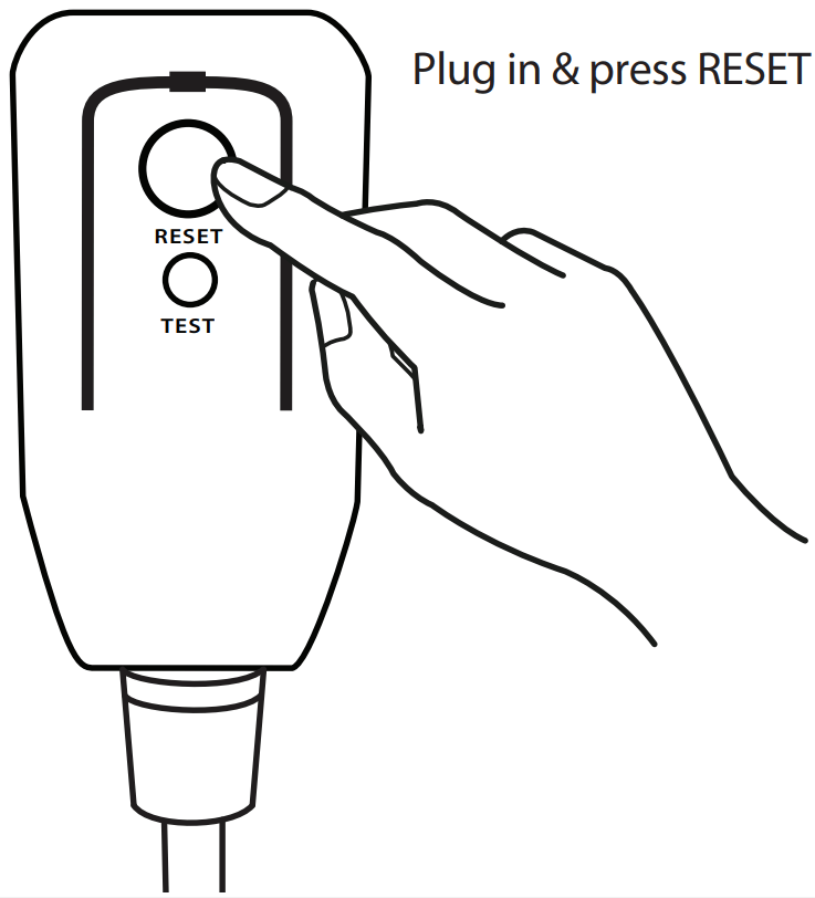
The power supply cord contains a current measuring device that detects damage to the power cord. Test your power supply cord as follows:
Plug in the air conditioner.
The power supply cord will have TWO buttons on the plug head. Press the TEST button. You will notice a click as the RESET button pops out.
Press the RESET Button. You will notice a click as the button engages.
The power supply cord is now supplying electricity to the unit. (On some products this is also indicated by a light on the plug head.)
NOTE
The power supply cord with this air conditioner contains a current detection device designed to reduce the risk of fi re.
In the event that the power supply cord is damaged, it can not be repaired. It must be replaced with a cord from the manufacturer.
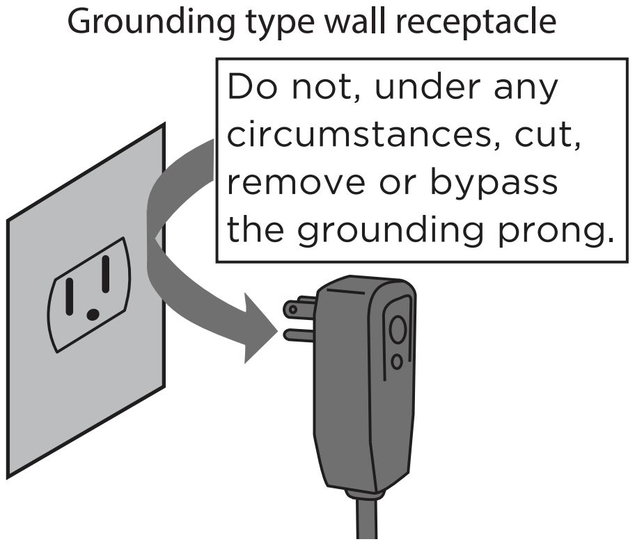
Power supply cord with 3-prong grounding plug and current detection device.
NOTE
Do not use this device to turn the unit on or off .
Always make sure the RESET button is pushed in for correct operation.
The power supply cord must be replaced if it fails to reset when either the TEST button is pushed, or it can not be reset. Please contact Customer Service.
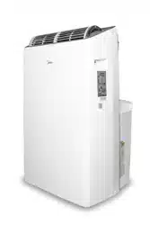
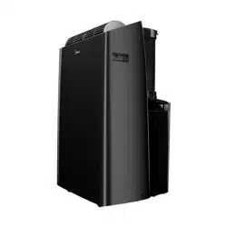
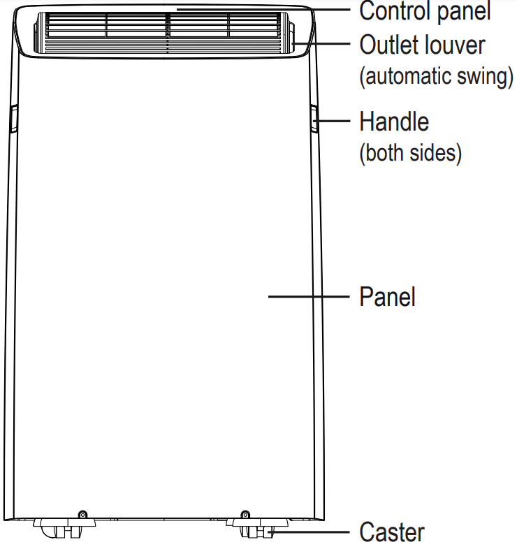
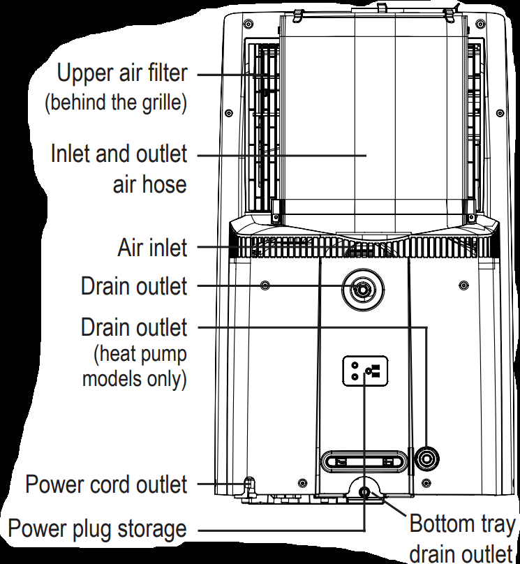
Preparation
Front
Rear
Unit Operating Temperature Range:
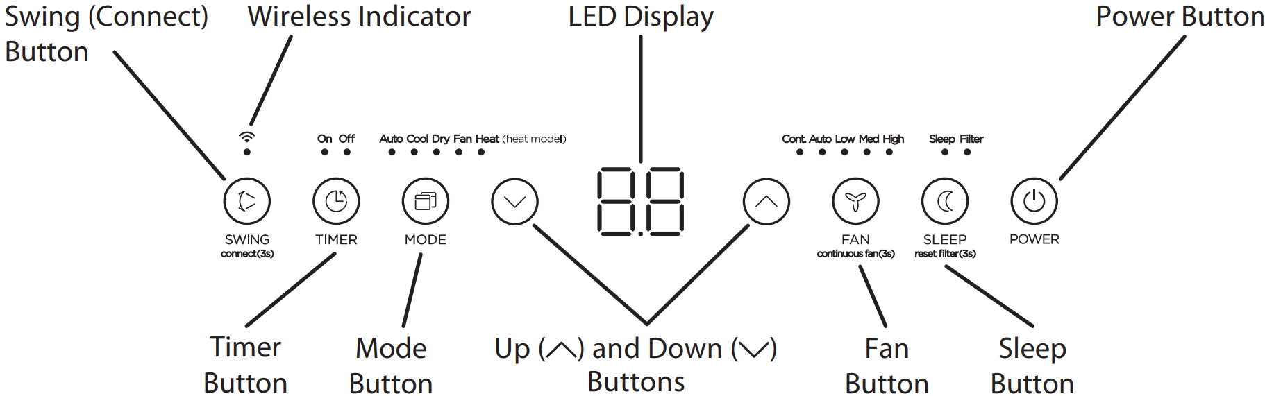
Control Panel Features
Swing Button
Used to initiate the Auto Swing feature. When the operation is ON, pressing the SWING button can stop the louver at the desired angle.
Connect Button
Also used to initiate the wireless connection mode.
To initiate the wireless connection mode, power on the air conditioner then press the SWING button for 3 seconds. The LED DISPLAY will show ‘AP’ to indicate the unit is in wireless connection mode. Refer to the app connection instructions to sh the connection process.
If the connection is successful, the unit will exit wireless connection mode and illuminate the wireless LED. If the connection fails, the unit will exit wireless connection mode automatically after 8 minutes and the wireless LED does not illuminate.
Note: The wireless connection process must be completed within 8 minutes after powering the air conditioner on.
Timer button
Used to initiate the AUTO ON start time and AUTO OFF stop time program. The timer on or o t will illuminate depending on the selected setting.
Fan button
Controls the fan speed. Press to control the fan speed in four steps - LOW, MID, HIGH and AUTO. The selected fan speed light will illuminate.
NOTE: Applicable to models with the Constant Fan feature. In COOL or DRY mode, press the Fan button for the constant fan function.
When the function is turned on, the constant fan light will illuminate, indicating the fan will run constantly, independent of compressor operation. the constant fan light will go out, indicating that the fan will stop when the compressor stops.
Mode button
Selects the desired operating mode. Each time you press the button, a mode is selected in a sequence that goes from AUTO, COOL, DRY, FAN and HEAT (cooling only models excluded).
The mode light illuminates and indicates the selected mode.
Up and Down buttons
Used to increase/decrease temperature settings in 1° increments in a range of 60*F/16°C to 86°F/30°C or the TIMER setting in a range of 0 ~ 24hrs.
To change between °F or °C, simultaneously press and hold the Up and Down buttons for seconds.
Power button
Power switch on/o
Sleep button
Press SLEEP button to initiate the SLEEP operation and the sleep light illumiantes.Press SLEEP button again to stop the SLEEP operation and the sleep light turns dark. Press SLEEP button for 3 seconds operation. The LED(the light above the button) will illuminate after 250 hours of operation.
LED display
Shows the set temperature in °F (Degrees Fahrenheit) or °C (Degrees Celsius) and the Auto-timer settings. While on FAN modes, it shows the room temperature.
The unit may stop operation or continue to run safely. If the error codes appear, wait for about 10 minutes. The problem may resolve itself. If not, disconnect the power, then connect it again. Turn the unit on. If the problem persists, disconnect the power and contact your nearest customer service center. Error code appears andbegins with the letters as the following in the window display of indoor unit:EH(xx), EL(xx), EC(xx), PH(xx), PL(xx), PC(xx) ows Error codes and protection code:
Operating Instructions
COOL operation
Press the “MODE” button until the “COOL” indicator light comes on.
Press the ADJUST buttons Up or Down to select your desired room temperature. The temperature can be set within a range of 60°F~86°F/16°C~30°C.
Press the “FAN SPEED” button to choose the fan speed.
HEAT operation
Press the “MODE” button until the “ ” indicat HEAT or light comes on.
Press the ADJUST buttons Up or Down to select your desired room temperature. The temperature can be set within a range of 60°F~86°F/16°C~30°C.
Press the “FAN SPEED” button to choose the fan speed. For some models, the fan speed cannot be adjusted while in HEAT mode.
DRY operation
Press the “MODE” button until the “DRY” indicator light comes on.
While in this mode, you cannot select a fan speed The fan motor operates at AUTO speed.
Keep windows and doors closed for the best dehumidifying effect.
Do not put the duct to window ws and doors closed for the best ect.
AUTO operation
When you set the air conditioner to AUTO mode, it will automatically select cooling, heating (cooling only models excluded), or fan only operation depending on what temperature you have selected and the current room temperature.
The air conditioner will control room temperature automatically according to the temperature point set by you.
Under AUTO mode, you cannot select the fan speed.
FAN operation
Press the “MODE” button until the ”FAN“ indicator light comes on.
Press the “FAN SPEED” button to choose the fan speed. The temperature cannot be adjusted.
Do not connect the duct to a window.
TIMER: Auto Start/Stop Operation Up and Down
When the unit is on, pressing the Timer button will initiate the Auto stop program. The TIMER OFF indicator light illuminates. Press the Up or Down button to select the desired time. Press the TIMER button again within 5 seconds. The Auto start program is initiated and the TIMER ON indicator light illuminates. Press the Up or Down button to select the desired Auto start time.
When the unit is off, press the Timer button to initiate the Auto start program. Pressing it again within five seconds will initiate the Auto stop program.
Press or hold the Up or Down button to change the Auto time by 0.5 hour increments, up to 10 hours, then at 1 hour increments up to 24 hours. The control will count down the time remaining until start.
The system will automatically revert back to display the previous temperature setting if there is no operation within 5 seconds.
Turning the unit ON or OFF at any time or adjusting the timer setting to 0.0 will cancel the Auto Start/Stop timer program.
Should a malfunction occur, the Auto Start/Stop timed program will also be cancelled.
SLEEP operation
Pressing this button will increase (during cooling operation) or decrease (during heating operation, applicable models) 2°F/1°C after minutes. The temperature will again increase (cooling) or decrease heating) by another 2°F/1°C after an additional 30 minutes. This new temperature will be maintained for 7 hours before returning to the originally selected temperature. This ends the Sleep mode and the unit will continue to operate as originally programmed.
NOTICE The SLEEP operation feature is unavailable in FAN or DRY mode.
Other Features
COMFORT SENSE feature
This feature can ONLY be activated from the remote control. The remote control serves as a remote thermostat allowing for the precise temperature control at its location, which must be within 26 feet of the air conditioner. To activate the Comfort Sense feature, point the remote control towards the unit and press the set button to select. The remote’s display will show the actual temperature at its location (as long as it is within the 26 feet of the air conditioner). The remote control will send this signal to the air conditioner every 3 minutes until the C-Sense function is selected again. If the unit does not receive the Comfort Sense signal during any 7 minutes interval, the unit will exit the Comfort Sense mode. NOTE: This feature is unavailabe under FAN or DRY mode.
AUTO-RESTART
If the unit shuts off unexpectedly due to a power outage, it will restart with the previously set function automatically when the power resumes.
WAIT 3 MINUTES BEFORE RESUMING OPERATION
After the unit has stopped, it cannot be restarted until 3 minutes time has elapsed. This is to protect the unit. Operation will automatically resume after 3 minutes.
AIRFLOW DIRECTION ADJUSTMENT
The louver can be adjusted automatically using the SWING button.
When the Power is ON, the louver opens fully.
Press the SWING button on the panel or remote controller to initiate the Auto Swing feature. The louver will swing up and down automatically.
Please do not adjust the louver manually.
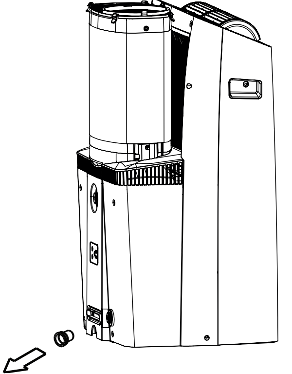
WATER DRAINAGE
During Dry modes, remove the upper drain plug from the back of the unit and install the drain connector (5/8” universal female adapter) with a 3/4“ hose (not included)
For models without drain connector, just attach the drain hose to the hole. Place the end of the hose directly in the drain area you’re using.
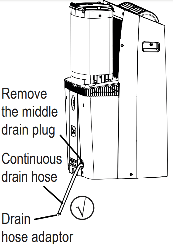
WATER DRAINAGE (Under heat mode)
Remove the middle drain plug from the back of the unit and install the drain connector (5/8” universal female adapter) with a hose (not included). For models without the drain connector, attach the drain hose to the connector. Place the end of the hose in the drain area you’re using.
NOTICE
The drain hose can be elevated up to 6ft (1.8m). Direct the hose toward the drain, making sure that there are no kinks that will restrict water ow. Place the end of the hose into the drain and make sure the end of the hose is directed downward (See Figs with ).
Figures with are installations not recommended by the manufacturer. When the continuous drain hose is not used, ensure firmly to prevent leaks.
When the water level of the bottom tray reaches a predetermined level, the unit beeps 8 times. The digital display shows “P1.” At this time the air conditioning/ cation process will immediately stop. However, the fan motor will continue to operate (this is normal). Carefully move the unit to a drain location, remove the bottom drain plug and let the water drain away. Reinstall the bottom drain plug and restart the machine until the “P1” symbol disappears. If the error repeats, call for service.
NOTICE Be sure to reinstall the bottom drain plug firmly to prevent leakage before using the unit.
Installation Instructions
Location
Your installation location should meet the following requirements:
Make sure that you install your unit on an even surface to minimize noise and vibration.
The unit must be installed near a grounded plug, and the Collection Tray Drain (found on the back of the unit) must be accessible.
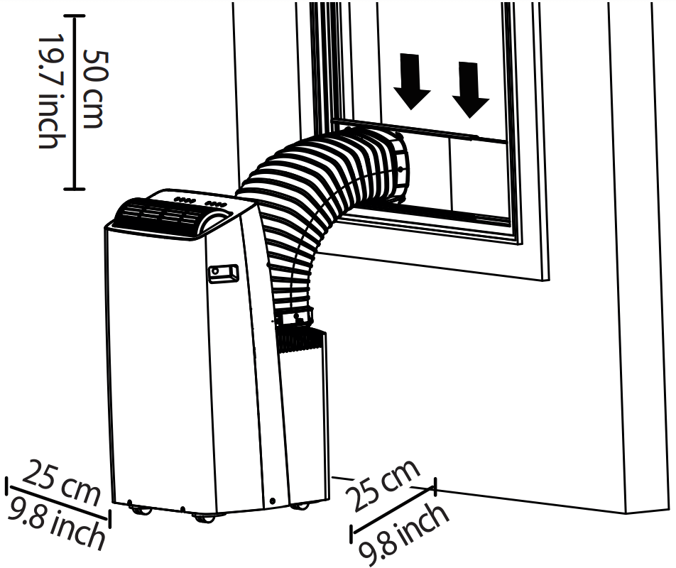
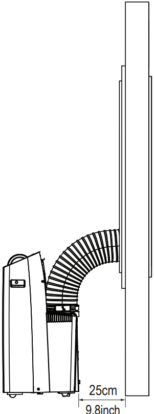
The unit should be located at least 9.8” cm) from the nearest wall to ensure proper air conditioning. The horizontal louver blade should be at least 50cm (19.7”) away from obstacles.
DO NOT cover the Intakes, Outlets or Remote Signal Receptor of the unit, as this could cause damage to the unit.
Recommended Installation
NOTICE The appearance of your unit might be slightly different.
WARNING
This air-conditioning unit is a hermetically sealed unit that contains fluorinated gasses. For specific information on the type of gas and the amount, please refer to the relevant label on the unit itself.
Service, maintenance or repair of this unit must be performed by a certifed technician.
Product recycling must be done according to local regulations.
Window Installation Kit
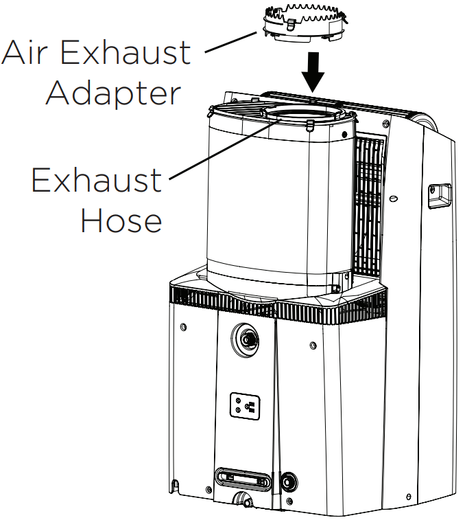
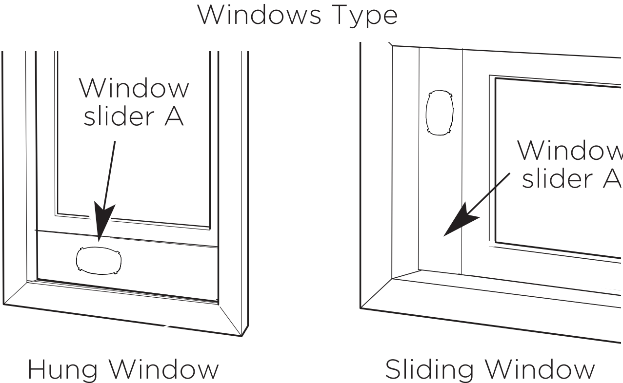
1: For Hung Window types only
Insert the Air Exhaust Adapter into the exhaust of the hose (the circle opening). Rotate the adapter clockwise until the locking tabs click and no longer rotates. Skip this step if installing into a horizontal sliding window.
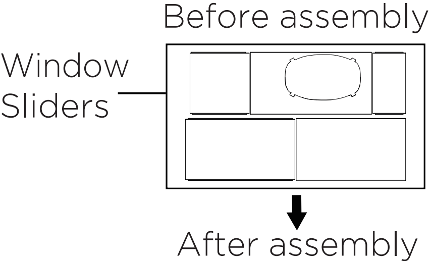
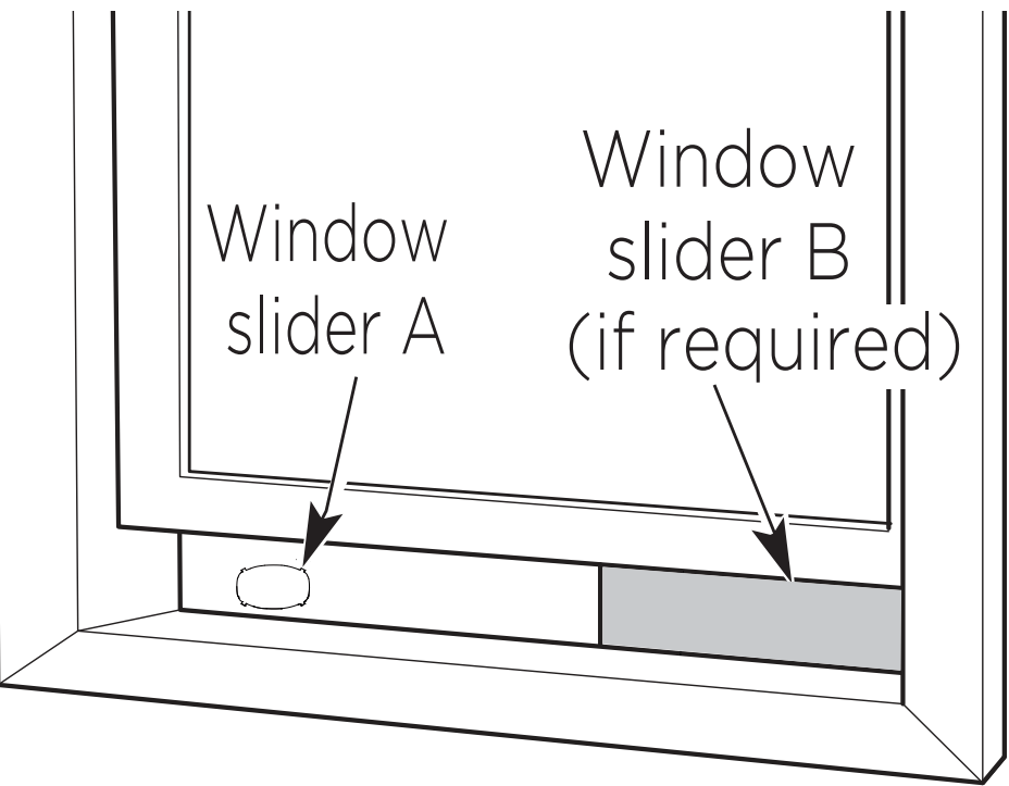
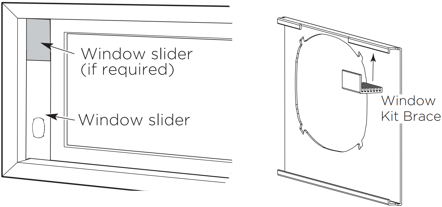
2: Preparing the adjustable window slider
Depending on the size of your window, adjust the size of the window slider.
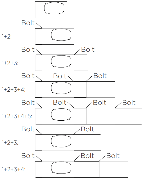
If the length of the window requires two or more window sliders, use the bolt to fasten the window sliders once they are adjusted to the proper length.
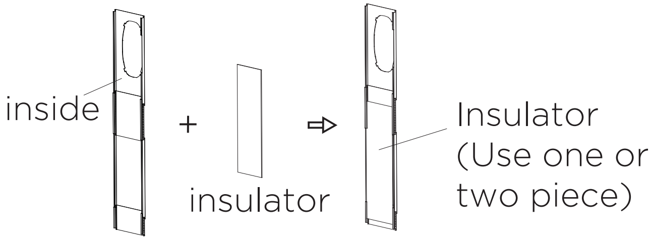
3. Paste the insulator on the inside of the Window sliders.
NOTE Once the Exhaust Hose assembly and Adjustable Window Slider are prepared, choose from one of the following two installation methods.
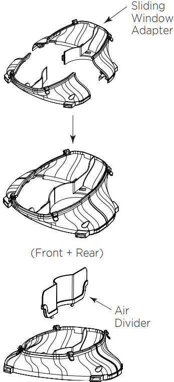
3: Assembling the Sliding Window Adapter (Only needed for Sliding Window applications).
Align both halves of the sliding window adapter and connect them. Then, attach the air divider to the newly formed window adapter on the outdoor side. The fully assembled adapter should look like the image at the left.
Type 1: Hung window installation
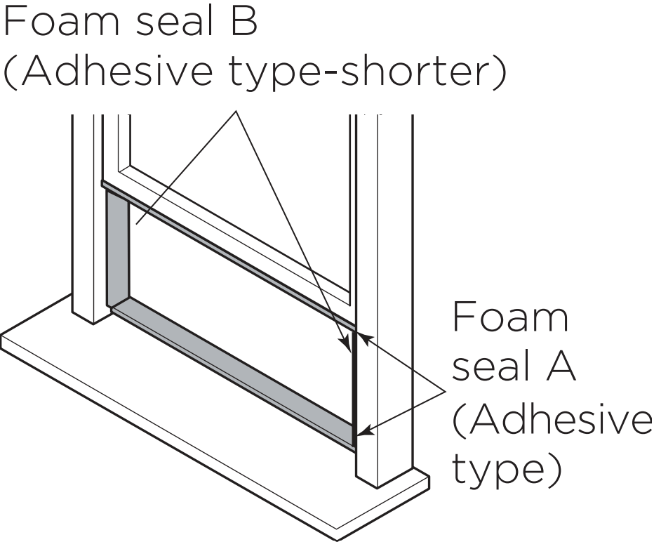
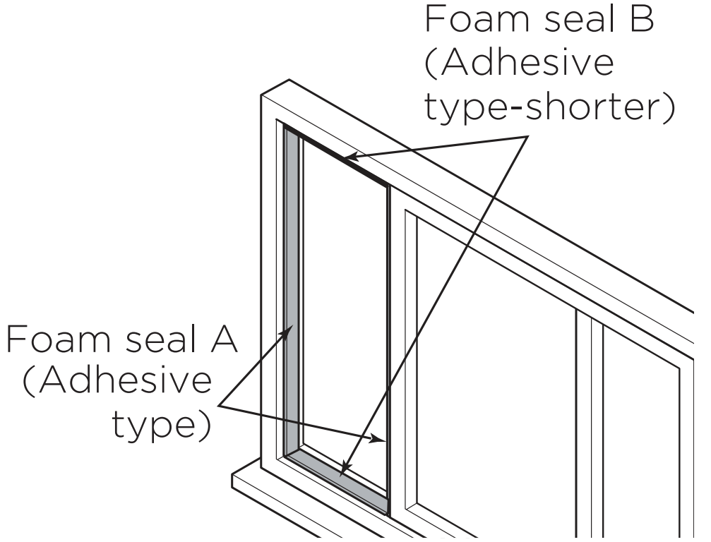
1. Cut the adhesive foam seal A and B strips to the proper lengths, and attach them to the window sash and frame as shown.
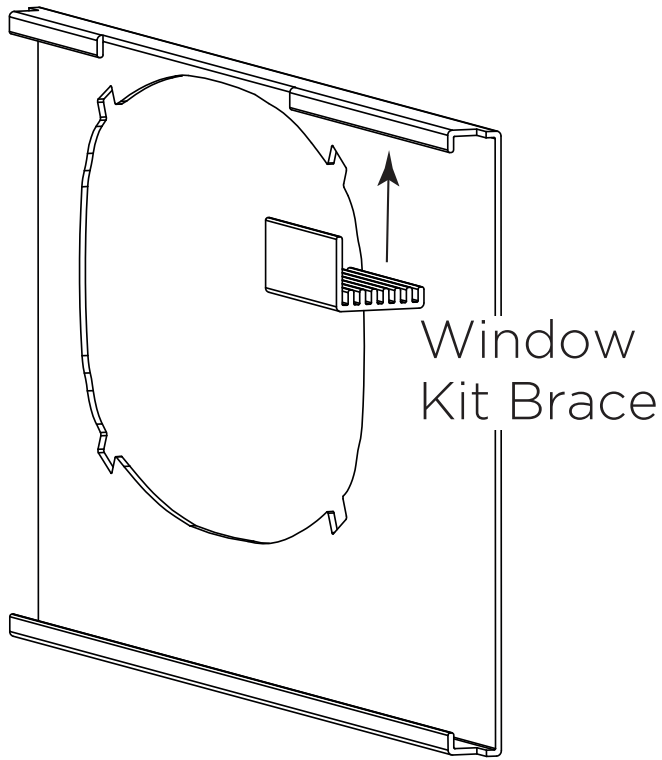
2. Insert the window slider assembly into the window opening. If the hose opening is covered by the window frame, rotate the panel so the thicker side faces the window frame. Attach the Window Kit Brace to the back of the hose panel – trim the brace if necessary.
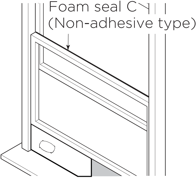
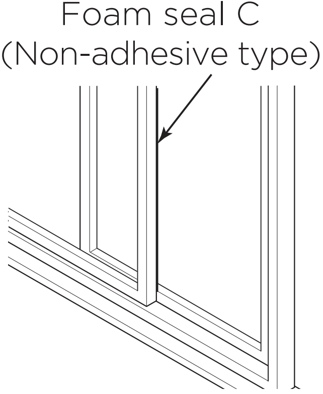
3. Cut the non-adhesive foam seal C strip to match the width of the window. Insert the seal between the glass and the window frame to prevent air and insects from getting into the room.
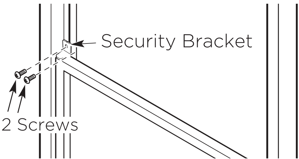
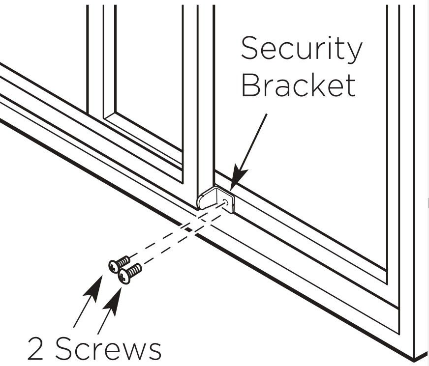
4. If desired, install the security bracket with 2 screws as shown.
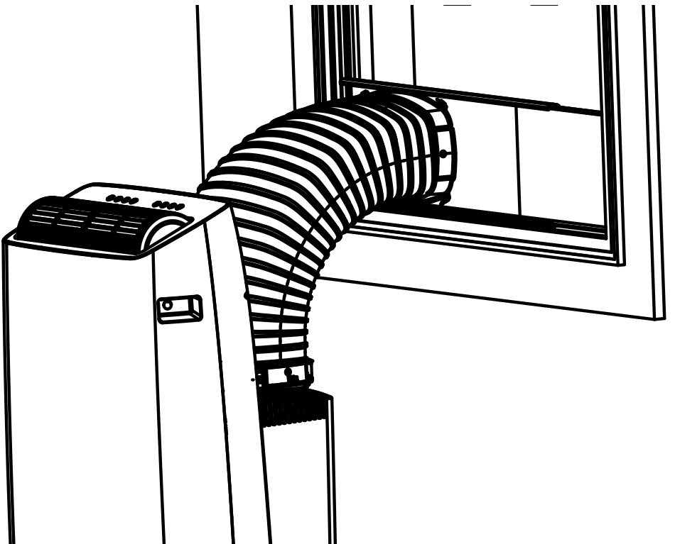
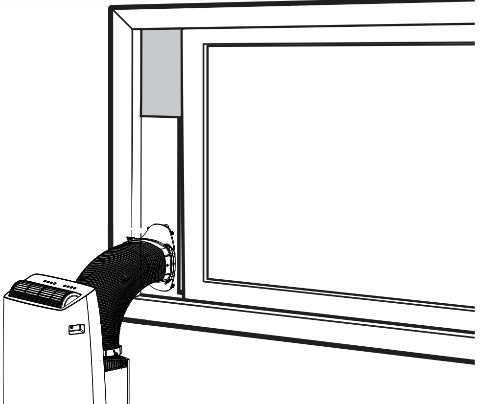
5. Attach the Hung Window Adapter to the hose by lining up the circles on the adapter the hose. Insert the window slider adapter into the hole of the window slider.
Type 2: Sliding window Installation (Optional)
1. Cut the adhesive foam seal A and B strips to the proper lengths, and attach them to the window sash and frame as shown.
2. Insert the window slider assembly into the window opening.
Insert the slider assembly into the window opening. If the hose opening is covered by the window frame, rotate the panel so the thicker side faces the window frame.
Attach the Window Kit Brace to the back of the hose panel – trim the brace if necessary.
3. Cut the non-adhesive foam seal C strip to match the window height. Insert the foam seal between the glass and the window frame to prevent air and insects from getting into the room.
4. If desired, install the security bracket with 2 screws as shown.
5. Attach the Sliding Window Adapter to the hose by lining up the circles on the adapter the hose. Insert the window slider adapter into the hole of the window slider.
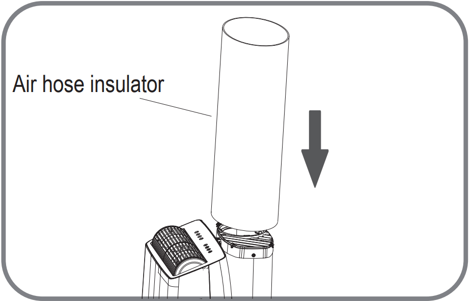
Air hose insulator Installation(only for heat pump mode)
NOTE: When the unit is at heat mode, the Air Hose insulator must be fixed in the hose of unit.
1. Cover the Air Hose with the Air Hose insulator.
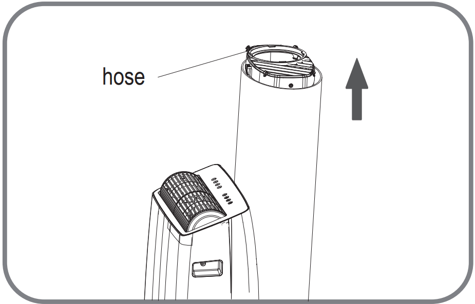
2. Pull out the Air Hose and cut the useless part of the Air Hose insulator.
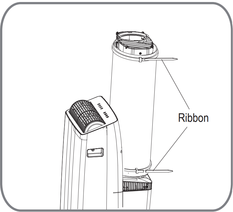
3. Tighten the air hose with the Ribbons and cut useless part.
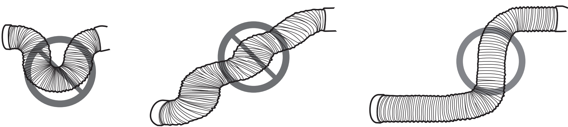
NOTICE
To ensure proper function, DO NOT overextend or bend the hose. Make sure that there are no objects within 20in (~500mm) of the inlet and outlet hose. All illustrations in this manual are for explanation purposes only, your air conditioner may be slightly dierent than shown.
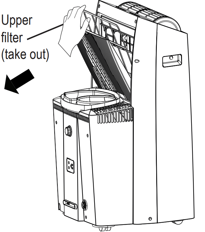
Care and Cleaning
Air Filter Cleaning
CAUTION: DO NOT operate the unit without filter because dirt and lint will clog it and reduce performance.
MAINTENANCE TIPS
Be sure to clean the air filter every 2 weeks for optimal performance.
The water collection tray should be drained immediately after P1 error occurs, and before storage to prevent mold.
In households with animals, you will have to periodically wipe down the grill to prevent blocked airflow due to animal hair.
Store the Unit When Not in Use
Drain the unit’s water collection tray according to the instructions in the following section.
Run the unit on FAN mode for 12 hours in a warm room to dry it and prevent mold.
Turn off the unit and unplug it.
Clean the air filter according to the instructions in the previous section. Reinstall the clean, dry filter before storing.
Remove the batteries from the remote control.
NOTICE
Be sure to store the unit in a cool, dark place. Exposure to direct sunlight or extreme heat can shorten the lifespan of the unit.
Troubleshooting Tips
Unit does not turn on when pressing ON/OFF button
Displays P1 Error Code and means the water collection tray is full. Turn off the unit, drain the water from the water collection tray, and restart the unit.
If room temperature is lower than the set temperature in COOL mode, reset the temperature.
Unit does not cool well
The air filter is blocked with dust or animal hair. Turn off the unit and clean the filter according to the instructions.
Exhaust hose is not connected or is blocked. Turn off the unit, disconnect the hose, check for blockage and reconnect the hose.
Temperature setting is too high; decrease the set temperature.
Make sure all windows and doors are closed.
The room area could be too large; doublecheck the cooling area.
Check the room for possible heat sources and remove them if possible.
The unit is noisy and/ or vibrates too much
The floor is not level. Place the unit on a flat, level surface.
The air filter is blocked with dust or animal hair. Turn off the unit and clean the filter according to the instructions.
The unit makes a gurgling sound
This sound is caused by the refrigerant flow inside the unit and is normal.
Unit will not connect to Wireless or App does not work (some modesl)
For additional support and troubleshooting tips, follow the link in the QR code:
The top of the window kit leans forward out of the window track
Ensure the Window Kit brace is installed properly.
#1 What should I look for first when purchasing a portable air conditioner?
The right air conditioner helps you cool a room efficiently. An undersized unit won't cool adequately while one that's too large will not remove enough humidity, leaving the air feeling damp. To find the proper air conditioner, determine the square footage of the room you want to cool by multiplying the room length by its width. You also need to know the air conditioner's BTU (British Thermal Unit) rating, which indicates the amount of heat it can remove from a room. A higher number means more cooling power for a larger room. (Be sure you are comparing only newer models to each other- older models may appear to have a higher capacity, but are actually the same). Be sure to “size up” if your portable air conditioner will be placed in a very sunny room, in a kitchen, or in a room with high ceilings. After you’ve found the right cooling capacity or your room, you can look at other features.

 and Down
  buttons
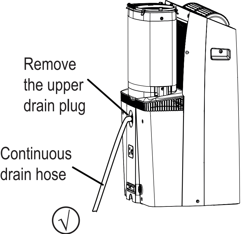
 ).
). are installations not recommended by the manufacturer. When the continuous drain hose is not used, ensure firmly to prevent leaks.