version F - 05 - 2021
Midea.com
USER MANUAL
en
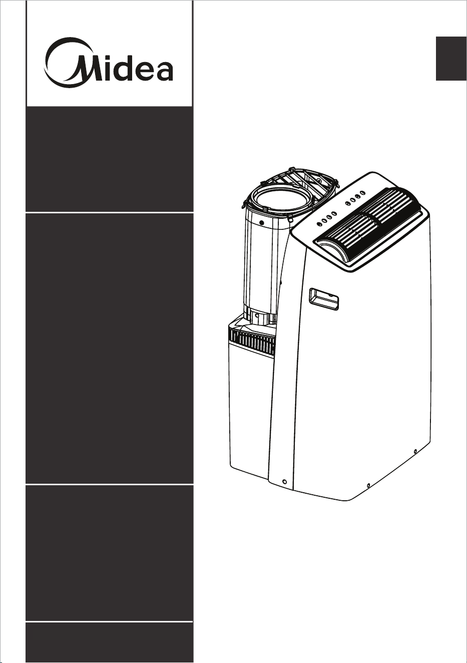
Duo Portable
Air Conditioner
Warning:
Before using this product,
please read this manual carefully
and keep it for future reference.
The design and specifications
are subject to change without
prior notice for product
improvement. Consult with your
dealer or the manufacturer for
details.
Capacity: 12000 ~ 14000BTU/h
version F - 05 - 2021
Page 2
Read This Manual
Inside you’ll find many helpful hints on how to use and maintain your air conditioner
properly. Just a little preventive care on your part can save you a great deal of time
and money over the life of your air conditioner. You’ll find many answers to common
problems in the troubleshooting tips - you should be able to fix most of them quickly
before calling service. These instructions may not cover every possible condition of
use, so common sense and attention to safety is required when installing, operating
and maintaining this product.
• For support, please call the Service Center at 1-866-646-4332.
• This appliance is not intended for use by people (including children) with
reduced physical, sensory, or mental capabilities or lack of experience and
knowledge, unless they have been given supervision or instruction concerning
use of the appliance by a person responsible for their safety.
• Children should be supervised to ensure that they do not play with the air
conditioner.
• The appliance shall be installed in accordance with national wiring regulations.
• Do not operate your air conditioner in a humid room such as a bathroom or
laundry room.
CAUTION
Owner’s Manual
SAFETY PRECAUTIONS ............................................................................. 3
OPERATING INSTRUCTIONS .................................................................... 8
INSTALLATION INSTRUCTIONS .............................................................. 12
CARE AND CLEANING ............................................................................. 19
TROUBLESHOOTING TIPS ..................................................................... 20
HEAT PUMP HOSE INSULATION FOAM ................................................ 21
REMOTE CONTROL AND APP INSTRUCTIONS ................................. 22
WARRANTY ............................................................................................... 30
Page 3
SAFETY PRECAUTIONS
To prevent injury to the user or other people and property damage, the instructions
shown here must be followed. Incorrect operation due to ignoring of instructions may
cause harm or damage. The level of risk is shown by the following indications.
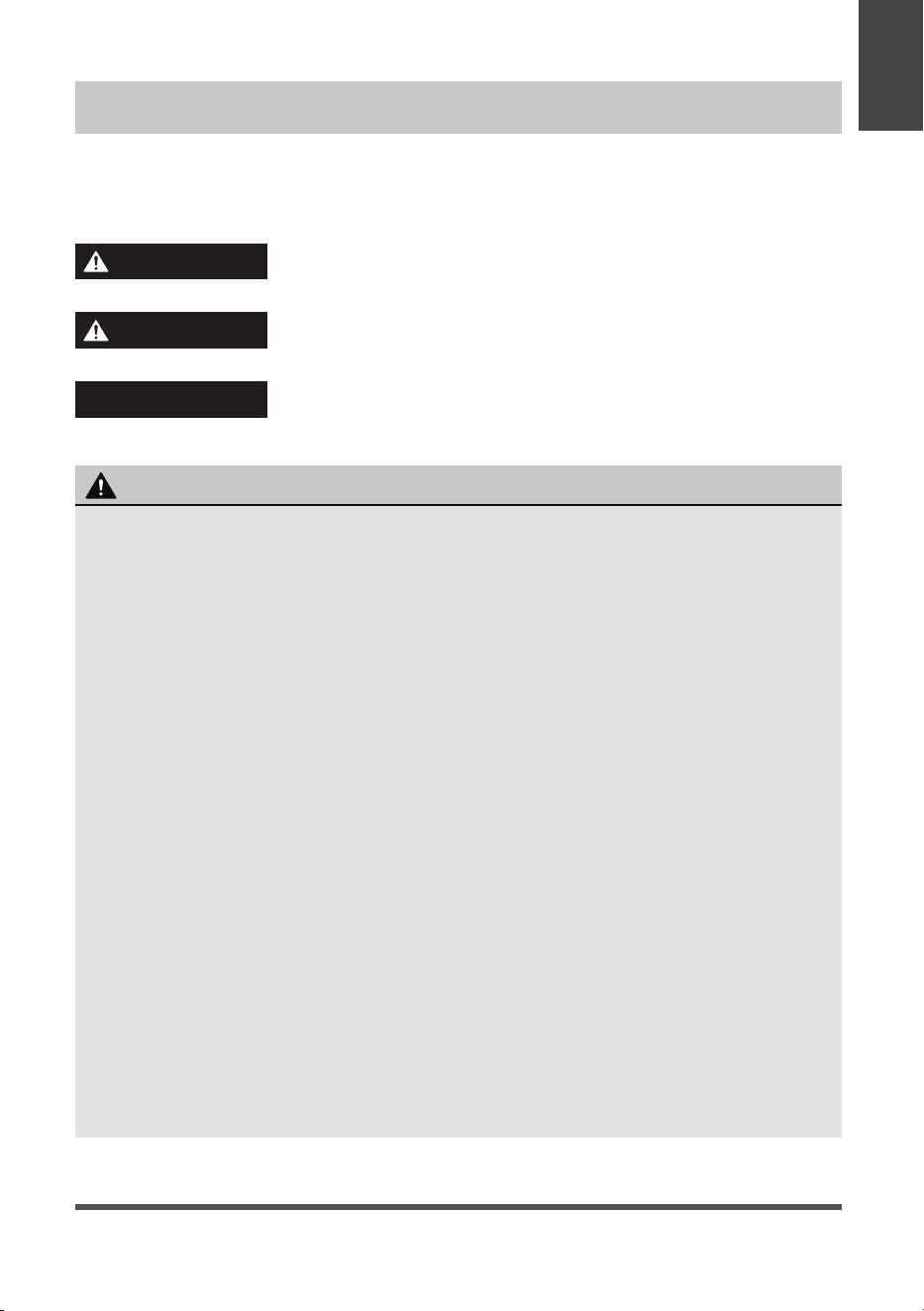
WARNING
• Be sure the air conditioner has been securely and correctly installed according to
the installation instructions in this manual. Save this manual for possible future use
in removing or installing this unit.
• Plug in power cord plug properly.
Otherwise, it may cause electric shock or fire due to excess heat generation.
• Do not modify power cord length or share the outlet with other appliances as it
may cause electric shock or fire due to overheating.
• Always ensure effective grounding.
Incorrect grounding may cause electric shock.
• Unplug the unit if you notice unusual sounds or smells or smoke coming from it.
A damaged product may cause fire and electric shock.
• Ventilate room before operating the air conditioner if there is a gas leakage from
another appliance.
• Do not operate or stop the unit by inserting or pulling out the power cord plug.
• Do not operate with wet hands or in very humid environments.
It may cause electric shock.
• Do not allow water to come into contact with any electric parts.
It may cause failure or electric shock.
• Do not use the socket if it is loose or damaged.
It may cause fire and electric shock.
• Do not use or keep the power cord close to heating appliances.
It may cause fire and electric shock.
• Do not use any devices or materials for installation that are not recommended in
this manual.
WARNING
This symbol indicates a hazardous situation which, if not
avoided, could result in death or serious injury.
CAUTION
This symbol indicates a hazardous situation, which, if not
avoided, could result in minor or moderate injury.
NOTICE
This symbol addresses practices not related to physical
injury.
Safety
Precautions
Page 4
WARNING
• Do not disassemble or modify unit.
It may cause failure and electric shock.
• Do not damage or use an alternate power cord.
It may cause fire and electric shock.
If the power cord is damaged, it must be replaced by the manufacturer or an
authorized service center or a similarly qualified person in order to avoid a hazard.
• Do not direct airflow straight into persons to avoid possible health hazard.
• Do not open the unit during operation.
It may cause electric shock.
• Do not use the power cord near flammable gas or combustibles, such as gasoline,
benzene, thinner, etc.
It may cause an explosion or fire.
• Do not let children hang on the air conditioner or bracket.
A serious injury may occur.
• Avoid fire hazard or electric shock. Do not use an extension cord or an adaptor
plug. Do not remove any prongs from the power cord.
• Be sure the air conditioner is properly grounded. To minimize shock and fire
hazards, proper grounding is important. The power cord is equipped with a
three-prong grounding plug for protection against shock hazards.
• Your air conditioner must be used in a properly grounded wall receptacle. If the
wall receptacle you intend to use is not adequately grounded or protected by a
time delay fuse or circuit breaker, have a qualified electrician install the proper
receptacle. Ensure the receptacle is accessible after the unit installation.
• Be sure the electrical service is adequate for the model you have chosen. This
information can be found on the serial plate, which is located on the side of the
cabinet and behind the grille.
CAUTION
• When the air filter is to be removed, do not touch the metal parts of the unit.
It may cause injury.
• When the unit needs cleaning, switch off, and turn off the circuit breaker.
Do not clean unit when power is on as it may cause fire, electric shock or injury.
• Do not place obstacles around air inlets or inside of air outlet.
It may cause failure or accident.
• Clean with a soft cloth only. Do not use strong detergents that contain wax or
thinners as it may damage the product.
• Use caution when unpacking and installing. Sharp edges could cause injury.
• Do not clean the air conditioner with water.
Water may enter the unit and degrade the insulation which could lead to
electric shock.
Safety
Precautions

Page 5
CAUTION
• Do not put a pet or house plant where it will be exposed to direct air flow.
This could injure the pet or harm the plant.
• Hold the plug by the head of the power plug when taking it out.
Otherwise, it may cause electric shock and damage.
• Ensure that the installation is properly secured to prevent the product from
potentially falling.
• Do not place heavy objects on the power cord and ensure that the cord is not
compressed.
Otherwise, there is danger of fire or electric shock.
• If water is spilled on the unit, turn off the unit and switch off the circuit breaker.
Isolate supply by taking the power-plug out and contact customer service.
• Do not use near gas stove or other gas burning appliances, as air flow may affect
gas combustion.
• Do not use for any purpose other than room comfort.
Do not use this air conditioner to preserve precision devices, food, pets, plants,
and art objects. It may cause deterioration.
• Turn off the main power switch if the unit is not to be used for an extended time.
• Always insert the filters securely. Clean filter once every two weeks.
Operation without filters may cause failure.
• Do not drink water drained from the air conditioner.
Safety
Precautions
Page 6
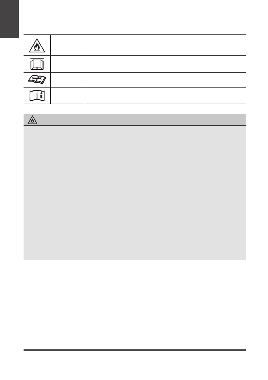
WARNING
This symbol shows that this appliance used a flammable
refrigerant. If the refrigerant is leaked and exposed to an
external ignition source, there is a risk of fire.
CAUTION
This symbol shows that the operation manual should be read
carefully.
CAUTION
This symbol shows that a service personnel should be handling
this equipment with reference to the installation manual.
CAUTION
This symbol shows that information is available such as the
operating manual or installation manual.
EXPLANATION OF SYMBOLS DISPLAYED ON THE UNIT
• Do not try to accelerate the defrosting process or methods of cleaning that are
not recommended by the manufacturer.
• The appliance shall be stored in a room without a continuously operating ignition
source (for example, open flames or an operating gas appliance) or an ignition
source (for example, an operating electric heater) close to the appliance. The
appliance shall also be stored in a room without ignition sources.
• Do not pierce or burn.
• Be aware that the refrigerants may not contain an odor.
• Keep ventilation openings clear of obstruction.
• Unit is only to be serviced by a Midea authorized servicer, please call Customer
Service at 1-866-646-4332 for support.
• Flammable refrigerant R32 is used within air conditioner. Please follow the
instructions carefully to handle, install, clean, and service the air conditioner
to avoid damage or hazard. Do not dispose of air conditioner in regular trash.
Contact qualified agency for proper disposal.
• No open fire or devices that generate spark/arcing shall be around the air
conditioner to avoid causing ignition of the flammable refrigerant used. Please
follow the instructions carefully to store or maintain the air conditioner to
prevent mechanical damage from occurring.
WARNING (for using R32 refrigerant only)
Safety
Precautions
Page 7
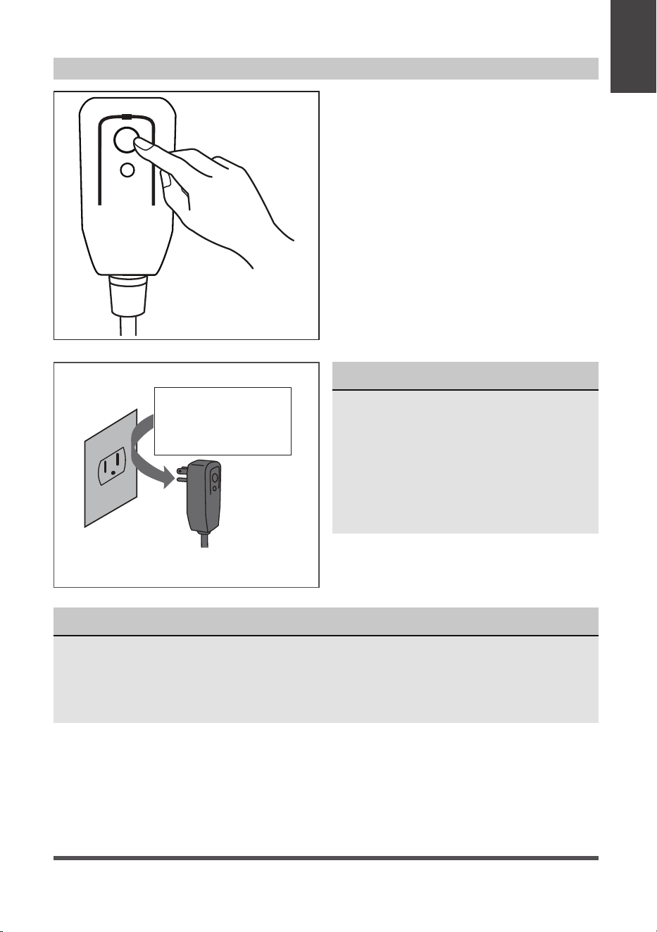
NOTICE
• Do not use this device to turn the unit on or off.
• Always make sure the RESET button is pushed in for correct operation.
• The power supply cord must be replaced if it fails to reset when either the TEST
button is pushed, or it can not be reset. Please contact Customer Service.
NOTICE
The power supply cord with this
air conditioner contains a current
detection device designed to reduce
the risk of fire.
In the event that the power supply
cord is damaged, it can not be
repaired. It must be replaced with a
cord from the manufacturer.
Grounding type wall receptacle
Do not, under any
circumstances, cut,
remove or bypass
the grounding prong.
Power supply cord with 3-prong grounding
plug and current detection device.
The power supply cord contains a current
measuring device that detects damage to
the power cord. Test your power supply
cord as follows:
1. Plug in the air conditioner.
2. The power supply cord will have TWO
buttons on the plug head. Press the
TEST button. You will notice a click as
the RESET button pops out.
3. Press the RESET Button. You will
notice a click as the button engages.
4. The power supply cord is now
supplying electricity to the unit. (On
some products this is also indicated
by a light on the plug head.)
RESET
TEST
Plug in &
press RESET
Operation of Current Device
Safety
Precautions
Page 8
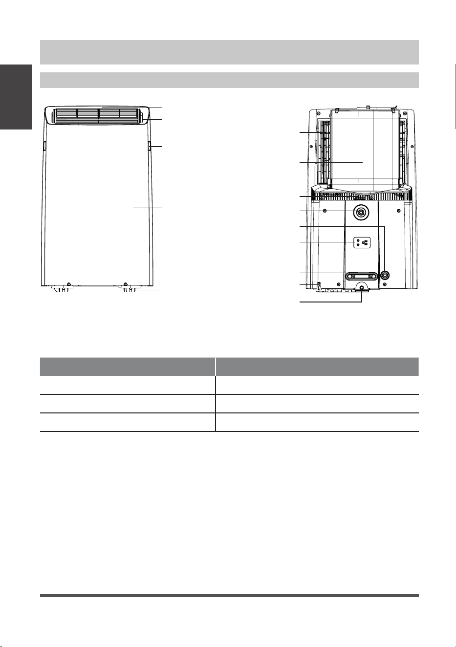
Preparation
OPERATING INSTRUCTIONS
Operating
Instructions
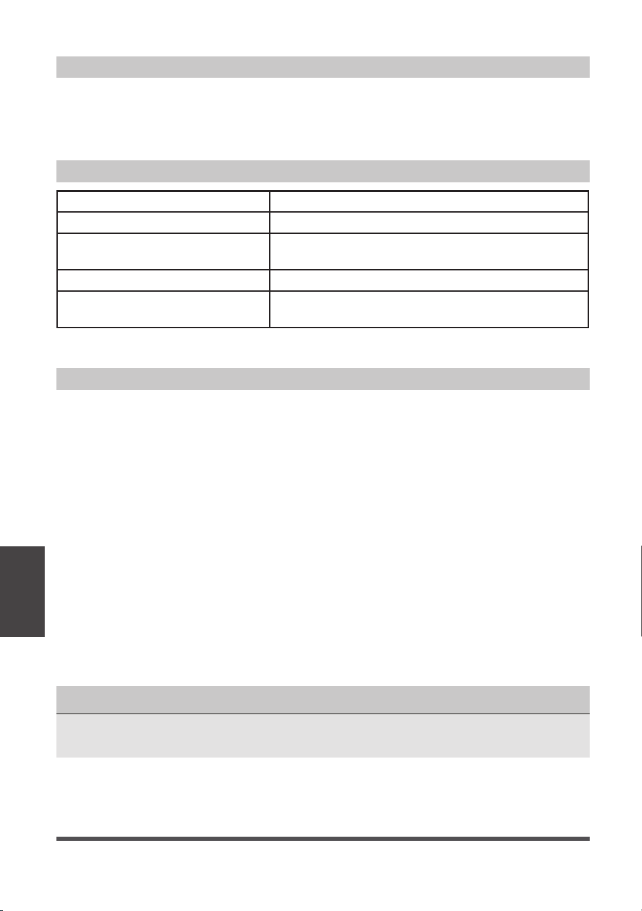
Unit Operating Temperature Range:
Mode Temperature Range
Cool 16°C ~ 35°C (60°F ~ 95°F)
Dry 13°C ~ 35°C (55°F ~ 95°F)
Heat Pump (for heat model) 5°C ~ 30°C (41°F ~ 86°F)
Handle
(both sides)
Power plug storage
Power cord storage
Upper air filter
(behind the grille)
Inlet and outlet
air hose
Air inlet
Drain Outlet (dry mode)
Drain Outlet (heating mode)
Power cord outlet
Outlet louver
(automatic swing)
Caster
raeRtnorF
Control panel
Panel
Drain Outlet
(excess condensate)
Page 9
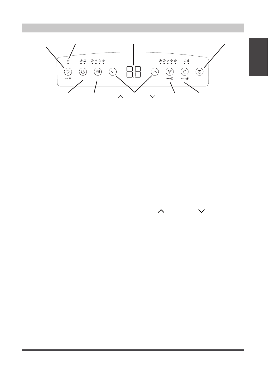
Control Panel Features
Operating
Instructions
Swing (Connect)
Button
Up (
) and Down ( )
Buttons
Mode
Button
Power Button
Sleep
Button
Fan
Button
Timer
Button
LED DisplayWireless Indicator
Swing Button
Used to initiate the Auto Swing feature. When
the operation is ON, pressing the SWING button
can stop the louver at the desired angle.
Connect Button
The swing button is also used to initiate the
wireless connection mode.To initiate the
wireless connection mode, power on the air
conditioner then press the SWING button for
3 seconds. The LED DISPLAY will show ‘AP’ to
indicate the unit is in wireless connection mode.
Refer to the app connection instructions to
finish the connection process.
If the connection is successful, the unit will exit
wireless connection mode and illuminate the
wireless LED. If the connection fails, the unit will
exit wireless connection mode automatically after 8
minutes and the wireless LED does not illuminate.
NOTE: The wireless connection process must be
completed within 8 minutes aft
er powering the
air conditioner on.
Timer Button
Used to initiate the AUTO ON start time and
AUTO OFF stop time program. The timer on
or off light will illuminate depending on the
selected setting.
Fan Button
Controls the fan speed. Press to control the fan
speed in four steps - LOW, MID, HIGH and AUTO.
The selected fan speed light (except AUTO) will
illuminate.
NOTE: Applicable to models with the Constant
Fan feature. In COOL or DRY mode, press the
Fan button for 3 seconds to turn on or off the
constant fan function.
When the function is turned on, the
constant fan light will illuminate,
indicating the fan will run constantly.
When the function is turned off, the
constant fan light will go out, indicating
that the fan will stop when the
compressor stops.
Mode Button
Selects the desired operating mode.
Each time you press the button, a mode
is selected in a sequence that goes from
AUTO, COOL, DRY, FAN and HEAT (Heat
models only). The mode light illuminates
and indicates the selected mode.
Up ( ) and Down ( ) Buttons
Used to increase/decrease temperature
settings in 1° increments in a range of
60°F/16°C to 86°F/30°C or the TIMER
setting in a range of 0 ~ 24hrs.
To change between °F or °C,
simultaneously press and hold the Up
and Down buttons for 3 seconds.
Power Button
Powers the unit on and off.
Sleep Button
Used to initiate the SLEEP operation.
LED Display
Shows the set temperature in °F
(Degrees Fahrenheit) or °C (Degrees
Celsius) and the Auto-timer settings.
While on DRY and FAN modes, it
shows the room temperature.
ON
OFF
Page 10
Operating
Instructions
COOL operation
• Press the “MODE” button until the “COOL”
indicator light comes on.
• Press the ADJUST buttons Up (
) or Down ( )
to select your desired room temperature.
The temperature can be set within a range of
60°F~86°F/16°C~30°C.
• Press the “FAN SPEED” button to choose the fan
speed.
HEAT operation (for heat model)
• Press the “MODE” button until the “HEAT”
indicator light comes on.
• Press the ADJUST buttons Up (
) or Down ( )
to select your desired room temperature.
The temperature can be set within a range of
60°F~86°F/16°C~30°C.
• Press the “FAN SPEED” button to choose the fan
speed.
• When entering heat mode, the fan may start
slower than expected. For some models, the fan
speed cannot be adjusted while in HEAT mode.
DRY operation
• Press the “MODE” button until the “DRY”
indicator light comes on.
• While in this mode, you cannot select a fan
speed. The fan motor operates at AUTO speed.
• Keep windows and doors closed for the best
dehumidifying effect.
AUTO operation
• When you set the air conditioner to AUTO mode,
it will automatically select cooling, heating (Heat
models only) or fan only operation depending
on what temperature you have selected and the
current room temperature.
• The air
conditioner will control room temperature
automatically according to the temperature point
set by you.
• Under AUTO mode, you cannot select the fan
speed.
FAN operation
• Press the “MODE” button until the
”FAN“ indicator light comes on.
• Press the “FAN SPEED” button to
choose the fan speed. The temperature
cannot be adjusted.
• Do not connect the duct to a window.
TIMER: Auto Start/Stop Operation
• When the unit is on, pressing the
Timer button will initiate the Auto stop
program. The TIMER OFF indicator light
illuminates. Press the Up (
) or Down
(
) button to select the desired time.
Press the TIMER button again within
5 seconds. The Auto start program is
initiated and the TIMER ON indicator
light illuminates. Press the Up (
) or
Down (
) button to select the desired
Auto start time.
• When the unit is off, press the Timer
button to initiate the Auto start program.
Pressing it again within five seconds will
initiate the Auto stop program.
• Press or hold the Up (
) or Down ( )
button to change the Auto time by 0.5
hour increments, up to 10 hours, then
at 1 hour increments up to 24 hours.
The control will count down the time
remaining until start.
• The system will automatically
revert back to display the previous
temperature setting if there is no
operation within 5 seconds.
• Turning the unit ON or OFF at any time
or adjusting the timer setting to 0.0
will cancel the Auto Start/Stop timer
program.
• Should a malfunction occur, the Auto
Start/Stop timed program will also be
cancelled.
Shows Error codes and protection code:
E1 - Room temperature sensor error.
E2 - Evaporator temperature sensor error.
E3 - Condenser temperature sensor error (select
models).
E4 - Display panel communication error.
P1 - Bottom tray is full - Connect the drain hose and
drain the collected water away. If protection
code repeats, call for service.
NOTICE
When one of these error codes occurs,
turn off the unit and check for any
obstructions. Restart the Unit. If the
malfunction persists, turn off the unit
and unplug the power cord and contact
customer service at 1-866-646-4332.
Operating Instructions

Page 11
Operating
Instructions
SLEEP operation
Pressing this button will increase (during
cooling operation) or decrease (during
heating operation, applicable models) 2°F/1°C
after 30 minutes. The temperature will again
increase (cooling) or decrease (heating)
by another 2°F/1°C after an additional 30
minutes. This new temperature will be
maintained for 7 hours before returning to
the originally selected temperature. This ends
the Sleep mode and the unit will continue to
operate as originally programmed.
NOTICE
The SLEEP operation feature is
unavailable in FAN or DRY mode.
COMFORT SENSE feature
This feature can ONLY be activated from the remote control. The remote control serves
as a remote thermostat allowing for the precise temperature control at its location, which
must be within 26 feet of the air conditioner. To activate the Comfort Sense feature, point
the remote control towards the unit and press the SET button to select. The remote’s display
will show the actual temperature at its location (as long as it is within the 26 feet of the
air conditioner). The remote control will send this signal to the air conditioner every 3
minutes until the C-Sense button is select again. If the unit does not receive the Comfort
Sense signal during any 7 minutes interval, the unit will exit the Comfort Sense mode.
NOTE: This feature is unavailabe under FAN or DRY mode.
AUTO-RESTART
If the unit shuts off unexpectedly due to a power outage, it will restart with the previously
set function automatically when the power resumes.
WAIT 3 MINUTES BEFORE RESUMING OPERATION
After the unit has stopped, it cannot be restarted until 3 minutes time has elapsed. This is
to protect the unit. Operation will automatically resume after 3 minutes.
AIRFLOW DIRECTION ADJUSTMENT
The louver can be adjusted automatically using the SWING button.
• When the Power is ON, the louver opens fully.
• Press the SWING button on the panel or remote controller to initiate the Auto Swing
feature. The louver will swing up and down automatically.
• Please do not adjust the louver manually.
Other Features
Page 12
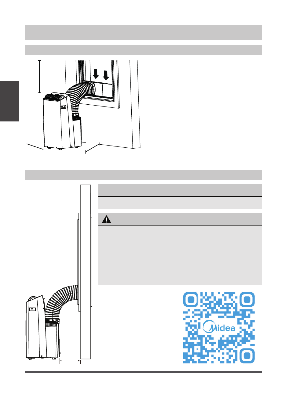
INSTALLATION INSTRUCTIONS
Choosing the Right Location
Recommended Installation
Installation
Instructions
Your installation location should meet the
following requirements:
• Make sure that you install your unit on
an even surface to minimize noise and
vibration.
• The unit must be installed near a
grounded plug, and the Collection Tray
Drain (found on the back of the unit)
must be accessible.
• The unit should be located at least 9.8”
(25cm) from the nearest wall to ensure
proper air conditioning.
• DO NOT cover the Intakes, Outlets or
Remote Signal Receptor of the unit, as
this could cause damage to the unit.
Scan this QR code to
watch an installation
video for your Midea Duo
Portable Air Conditioner:
NOTICE
The appearance of your unit might be slightly different.
25 cm
9.8 inch
25 cm
9.8 inch
9.8 inch
25 cm
50 cm
19.7 inch
WARNING
• This air-conditioning unit is a hermetically sealed unit
that contains fluorinated gasses. For specific information
on the type of gas and the amount, please refer to the
relevant label on the unit itself.
• Service, maintenance or repair of this unit must be
performed by a certified technician.
• Product recycling must be done according to local
regulations.
Page 13
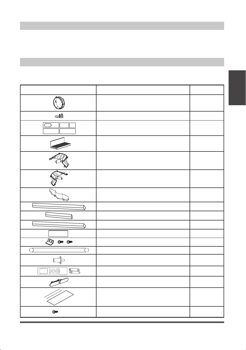
Tools Needed
Accessories
Installation
Instructions
Your Window Installation Kit fits windows 19.1” – 63.8” (48.4-162 cm). Please doublecheck
all packaging materials to make sure accessories do not get accidentally thrown away.
• Phillips screwdriver
• Tape measure or ruler
• Knife or scissors
noitpircseDtraP
Air exhaust adapter
Window Sliders
Window Kit Brace
Sliding Window Adapter – Front
Sliding Window Adapter – Rear
Sliding Window Adapter – Air Divider
Bolt
Foam seal A (adhesive)
Foam seal B (adhesive)
Foam seal C (Non-adhesive)
Security bracket and 2 screws
Drain hose
Drain hose adaptor
(For heat pump mode only)
Remote controller and battery
1 pc
1 pc
1 pc
1 pc
1 pc
8 pc
5 pc
2 pc
1 pc
1 pc
4 pc
2 pc
1 set
1 set
Quantity
1 pc
1 pc
Heat pump hose insulation foam
(optional)
1 Screw ( on Exhaust adaptor)
1 set
Window Slider Foam (adhesive)
2 pc
• Saw (optional, to shorten window adaptor
for narrow windows).
Power Cord Buckle(For cooling only model)
Page 14
Window Installation Kit
Installation
Instructions
window
slider
window
dimension (mm)
window
dimension (inch)
a+b 484
~
592 19.1
~
23.3
b+c 592
~
696 23.3
~
27.4
a+b+c 696
~
802 27.4
~
31.6
b+e 802
~
896 31.6
~
35.3
a+b+e 896
~
998 35.3
~
39.3
a+b+c+d 998
~
1210 39.3
~
47.6
a+b+c+d+e 1210
~
1620 47.6
~
63.8
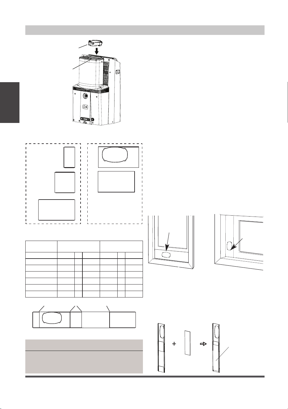
1: For Hung Window types only
Insert the Air Exhaust Adapter into the
exhaust of the hose (the circular opening)
for optimal performance. Rotate the
adapter clockwise until the locking tabs
click and it no longer rotates.
Skip this step if installing into a
horizontal sliding window.
The Air Exhaust adapter may interfere
with some window screens, and can be
removed if desired (Please note this may
slightly decrease performance).
2: Preparing the adjustable window slider
1. Depending on the size of your window,
adjust the size of the window slider.
Use the combination of panels that
best fits your window opening.
2. If the length of the window requires
two or more window sliders, use the
bolt to fasten the window sliders once
they are adjusted to the proper length.
3. If installing in a sliding window, bolts
should be installed on both sides of the
window sliders.
Hung Window Sliding Window
Windows Type
Window
slider
Window
slider
Air Exhaust
Adapter
Exhaust
Hose
NOTICE
Once the Exhaust Hose assembly and Adjustable
Window Slider are prepared, choose from one of
the following two installation methods.
3: Applying insulation to the window slider
After assembling the window slider to your
proper dimension, cut and apply the foam
insulation sheets to the exterior side of the
window slider.
Window
Slider Foam
Window
Slider Foam
Three Window Sliders
with side holes
Two Window Sliders
without side hole
Use the table below to determine what combination
of Window Sliders is correct for your window
a b
c d
e
a b c d e
boltbolt bolt
Page 15
Installation
Instructions
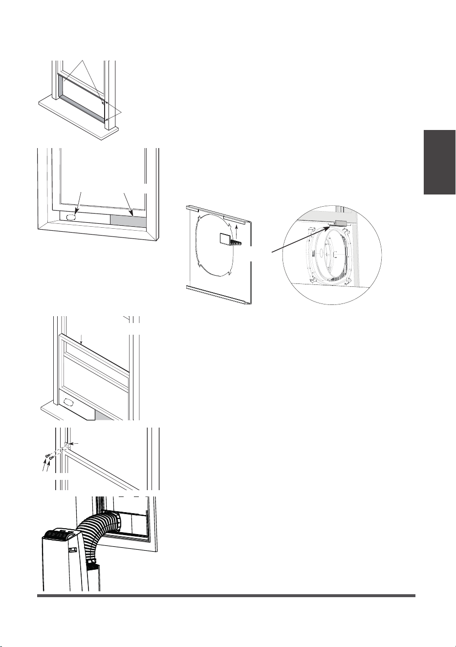
Type 1: Hung window installation
1. Cut the adhesive foam seal A and B strips to the
proper lengths, and attach them to the window
sash and frame as shown.
2. Insert the window slider assembly into the window
track. If the hose opening is covered by the lip of
the window frame, rotate the panel so the thicker
side faces the window frame. Attach the Window
Kit Brace to the back of the hose panel to brace
against the window so the window slider panels do
not lean inward.
Foam seal B
(Adhesive type-shorter)
Foam
seal A
(Adhesive
type)
Window
slider
Window
slider
(if required)
Window
Kit Brace
Foam seal C
(Non-adhesive type)
Security Bracket
2 Screws
3. Cut the non-adhesive foam seal C strip to match
the width of the window. Insert the seal between
the glass and the window frame to prevent air and
insects from getting into the room.
4. If desired, install the security bracket with 2 screws
as shown.
5. Attach the hose to the window slider panel by
inserting the end of the hose into the opening on
the slider.
Page 16
Installation
Instructions
Foam seal B
(Adhesive
type-shorter)
Foam seal A
(Adhesive
type)
Window slider A
Window slider B
(if required)
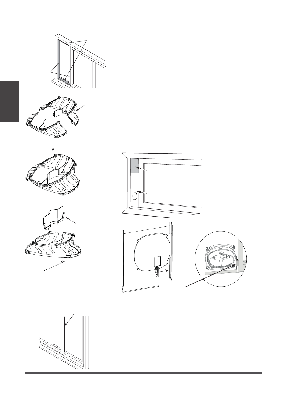
Type 2: Sliding window Installation (Optional)
1. Cut the adhesive foam seal A and B strips to the
proper lengths, and attach them to the window
sash and frame as shown.
2. Assembling the Sliding Window Adapter (Only
needed for Sliding Window applications): Align
both halves of the sliding window adapter and
connect them. Then, attach the air divider to the
newly formed window adapter on the outdoor
side. The fully assembled adapter should look like
the image at the left.
3. Insert the window slider assembly into the window
track. If the hose opening is covered by the window
frame, rotate the panel so the thicker side faces the
window frame. Attach the Window Kit Brace to the
back of the hose panel to brace against the window
so the window slider panels do not lean inward.
4. Be sure bolts are installed in both sides of the
window slider for improved rigidity.
Window
Kit Brace
Foam seal C
(Non-adhesive type)
5. Cut the non-adhesive foam seal C strip to match
the window height. Insert the foam seal between
the glass and the window frame to prevent air and
insects from getting into the room.
Sliding
Window
Adapter
(Front + Rear)
Air
Divider
1 screw
Page 17
Installation
Instructions
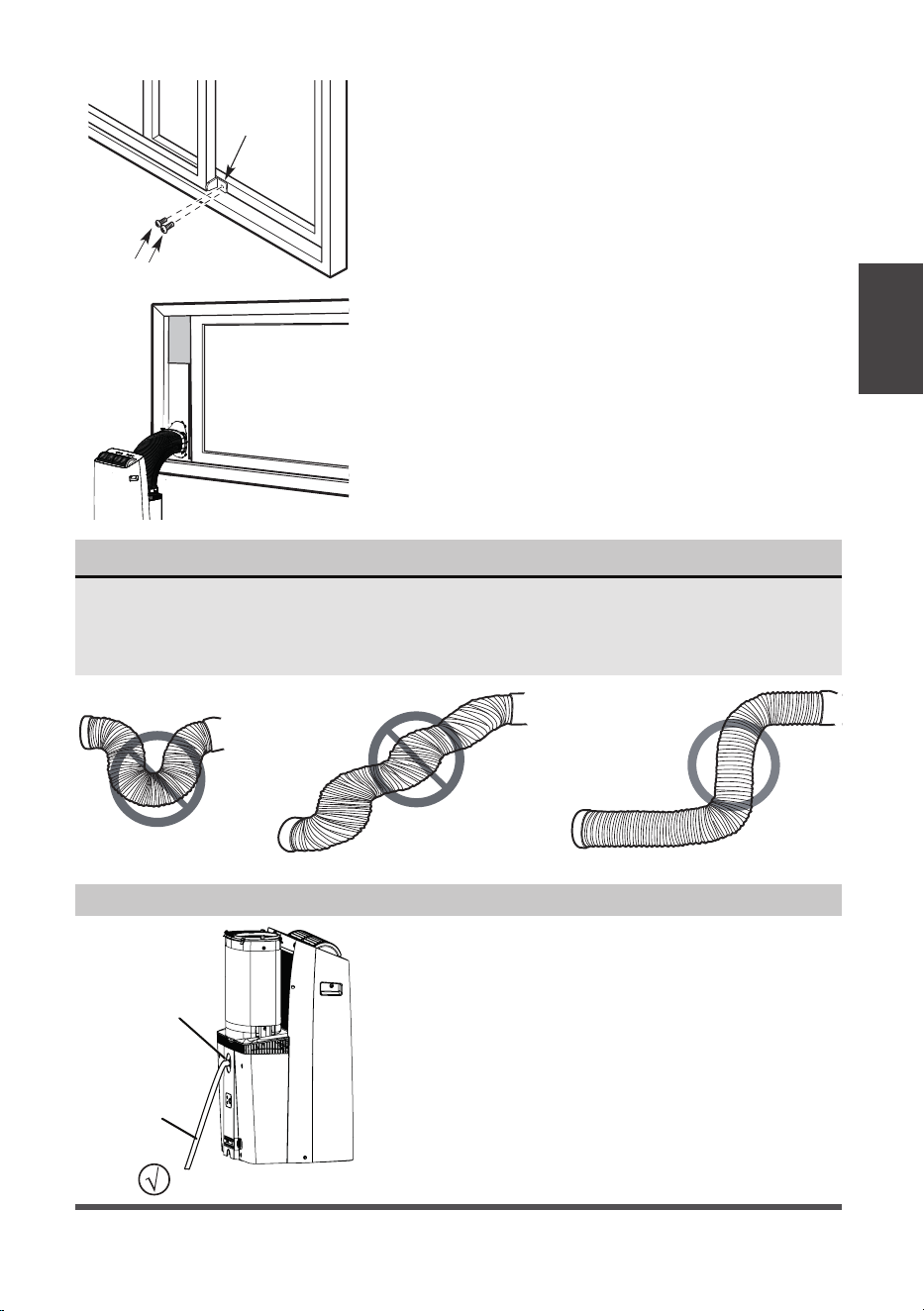
NOTICE
To ensure proper function, DO NOT overextend or bend the hose. Make sure that
there are no objects within 20in (~500mm) of the inlet and outlet hose.
All illustrations in this manual are for explanation purposes only, your air
conditioner may be slightly different than shown.
2 Screws
Security
Bracket
6. If desired, install the security bracket with 2
screws as shown.
7. Attach the Sliding Window Adapter to the hose
by lining up the circles on the adapter the hose.
Insert the window slider adapter into the hole of
the window slider.
Remove
the upper
drain plug
Continuous
drain hose
• During Dry modes, remove the upper drain plug
from the back of the unit and install the drain
hose.
For models without drain connector, just attach
the drain hose to the hole. Place the end of the
hose directly in the drain area you’re using.
Water Drainage
Page 18
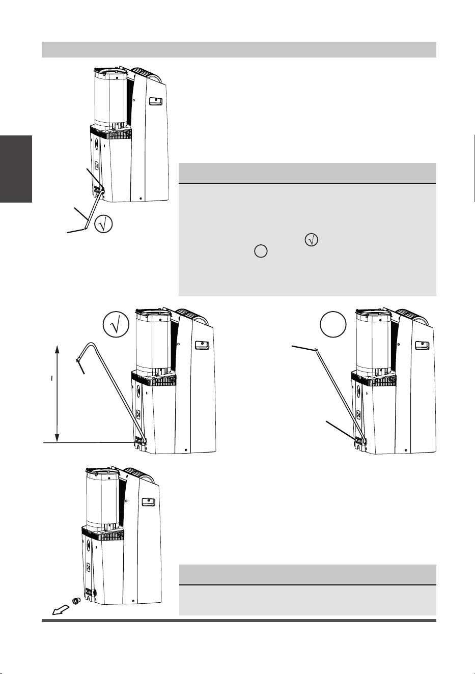
Water Drainage (For Heating Mode)
NOTICE
Be sure to reinstall the bottom drain plug firmly to
prevent leakage before using the unit.
NOTICE
Because this unit contains a condensate pump, the drain
hose can be elevated up to 6 ft. (1.8 m). Direct the hose
toward the drain, making sure there are no kinks that
will restrict water flow. Make sure the end of the hose is
directed downward (see fig. with check mark symbol).
The figure with
X
symbol is not recommended as the end
of the hose is not directed downward. When the continuous
drain hose is not used, ensure that the corresponding drain
plug and knob are installed firmly to prevent leaks.
Drain hose
adaptor
Press the power
cord buckle into
the rear cover.
Drain
hose
adaptor
Delivery lift < 6ft
X
Remove
the middle
drain plug
Continuous
drain hose
Drain
hose adaptor
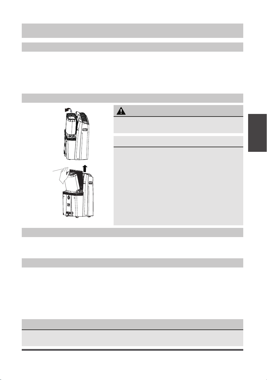
• While operating in heat pump mode, the unit will
produce condensate that must be drained. You must
install the drain hose when operating in heat mode. To
install the drain hose, remove the plug from the drain
port and attach the included hose. The universal drain
adaptor can be attached to the end of the included
hose. A 3/4” hose (not included) can be attached to
the adaptor if a longer hose length is required. Place
the end of the hose in the drain area you are using.
• When the water level of the bottom tray reaches a
predetermined level, the unit beeps 8 times. The digital
display shows “P1.” At this time the air conditioning/
dehumidification process will immediately stop. However,
the fan motor will continue to operate (this is normal).
Carefully move the unit to a drain location, remove the
bottom drain plug and let the water drain away. Reinstall
the bottom drain plug and restart the machine until the
“P1” symbol disappears. If the error repeats, call for service.
Installation
Instructions
Page 19
Safety Precautions
Air Filter Cleaning
Unit Cleaning
Store the Unit When Not in Use
CARE AND CLEANING
Care and
Cleaning
• Always unplug the unit before cleaning or servicing.
• DO NOT use flammable liquids or chemicals to clean the unit.
• DO NOT wash the unit under running water. Doing so causes electrical danger.
• DO NOT operate the machine if the power supply was damaged during cleaning.
A damaged power cord must be replaced with a new cord from the manufacturer.
Clean with a soft cloth only. Do not use strong detergents that contain wax or thinners
as it may damage the product
• Drain the unit’s water collection tray according to the instructions in the following section.
• Run the unit on FAN mode for 12 hours in a warm room to dry it and prevent mold.
• Turn off the unit and unplug it.
• Clean the air filter according to the instructions in the previous section. Reinstall
the clean, dry filte
r before storing.
• Remove the batteries from the remote control.
NOTICE
Be sure to store the unit in a cool, dark place. Exposure to direct sunlight or extreme
heat can shorten the lifespan of the unit.
CAUTION
DO NOT operate the unit without filter because
dirt and lint will clog it and reduce performance.
Maintenance Tips
• Be sure to clean the air filter every 2 weeks for
optimal performance.
• Clean the filter using water and ensure it is dry
before reinstalling.
• The water collection tray should be drained
immediately after P1 error occurs, and before
storage to prevent mold.
• In households with animals, you will have to
periodically wipe down the grill to prevent blocked
airflow due to animal hair.
Upper filter
(take out)
• Notice the air filter is integrated with the removable
grille cover.
Page 20
Troubleshooting
Tips
Before calling for service, review this list. It may save you time and expense. This list
includes common occurrences that are not the result of defective workmanship or
materials in this appliance.
TROUBLESHOOTING TIPS
NOTICE
Do not add extension to the exhaust hose(s)!
Problem Solution
Unit does not turn on
when pressing ON/
OFF button
Displays P1 Error Code and means the water collection tray is full.
Turn off the unit, drain the water from the water collection tray,
and restart the unit.
If room temperature is lower than the set temperature in COOL mode,
reset the temperature.
Unit does not cool well The air filter is blocked with dust or animal hair. Turn off the unit and
clean the filter according to the instructions.
Exhaust hose is not connected or is blocked. Turn off the unit,
disconnect the hose, check for blockage and reconnect the hose.
Temperature setting is too high; decrease the set temperature.
Make sure all windows and doors are closed.
The room area could be too large; doublecheck the cooling area.
Check the room for possible heat sources and remove them if possible.
The unit is noisy and/
or vibrates too much
The floor is not level. Place the unit on a flat, level surface.
The air filter is blocked with dust or animal hair. Turn off the unit and
clean the filter according to the instructions.
The unit makes a
gurgling sound
This sound is caused by the refrigerant flow inside the unit and is
normal.
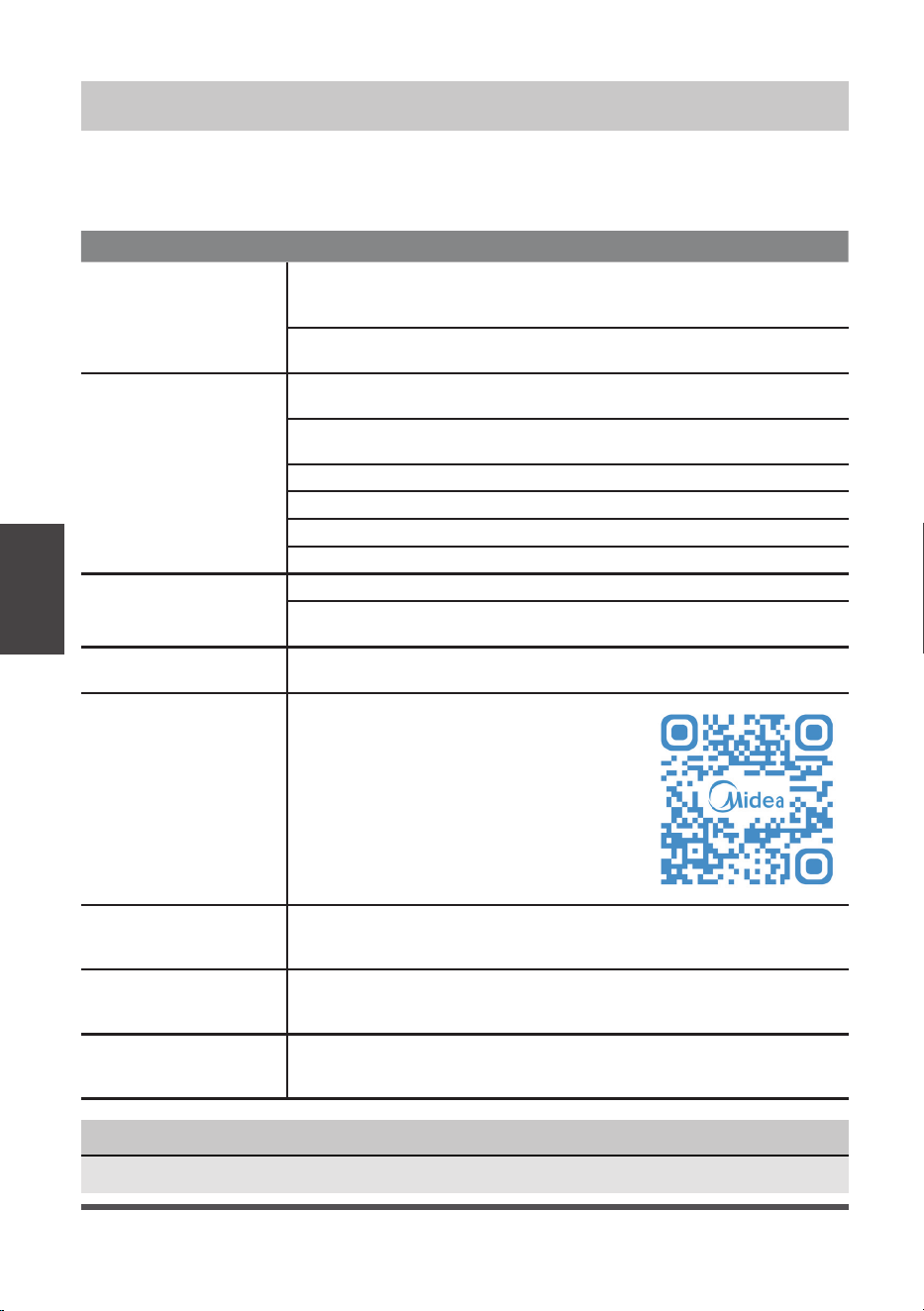
Unit will not connect
to Wireless or App
does not work (some
modesl)
For additional support and troubleshooting
tips, follow the link in the QR code:
The top of the window
kit leans forward out of
the window track
Ensure the Window Kit brace is installed properly.
In heating mode, the
fan speed is lower than
expected.
It is normal for the fan speed to start low in heating mode. The fan
speed should reach your desired setting after a few minutes of
operation.
Condensation collects
on the outer section of
the hose in heat mode
Apply the included hose insulation foam as shown on the next page.
Page 21
Heat Pump
Insulation Foam
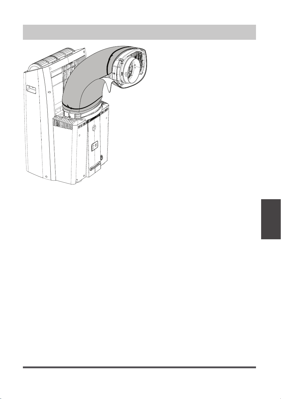
HEAT PUMP HOSE INSULATION FOAM
If you are experiencing condensation
on the outer section of the hose
during heating operation, apply the
included heat pump insulation foam
to the outside of the hose. Use the
included zip ties to secure the foam
around the hose.
Page 22
REMOTE CONTROL AND APP INSTRUCTIONS
Handling the Remote Control
Inserting and Replacing Batteries
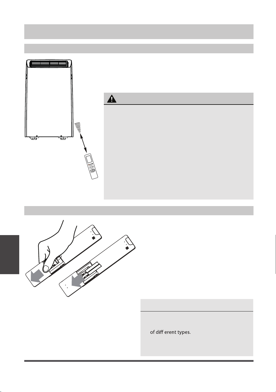
• The air conditioner will not operate if curtains, doors
or other materials block the signals from the remote
control to the unit.
• Prevent any liquid from spilling onto the remote
control. Do not expose the remote control to direct
sunlight or heat.
• If the infrared signal receiver on the indoor unit is
exposed to direct sunlight, the air conditioner may
not function properly. Use curtains to prevent the
sunlight from falling on the receiver.
• If other electrical appliances react to the remote
control, either move these appliances or consult
your local dealer.
CAUTION
Remote Control
and App
Instructions
LOCATION OF THE REMOTE CONTROL
Use the remote control within a distance of 26 ft. (8m)
from the air conditioner, pointing it towards the unit.
The unit will beep when it receives a signal.
26 ft (8 meters)
Your air conditioning unit may come with
two batteries AAA (some units). Put the
batteries in the remote control before use.
1. Slide the back cover from the remote
control downward, exposing the
battery compartment.
2. Insert the batteries, paying attention
to match up the (+) and (-) ends of the
batteries with the symbols inside the
battery compartment.
3. Slide the battery cover back into place.
BATTERY NOTES
For optimum product performance:
• Do not leave batteries in the remote control if
• Do not mix old and new batteries, or batteries
you don’t plan on using the device for more
than 2 months.
Page 23
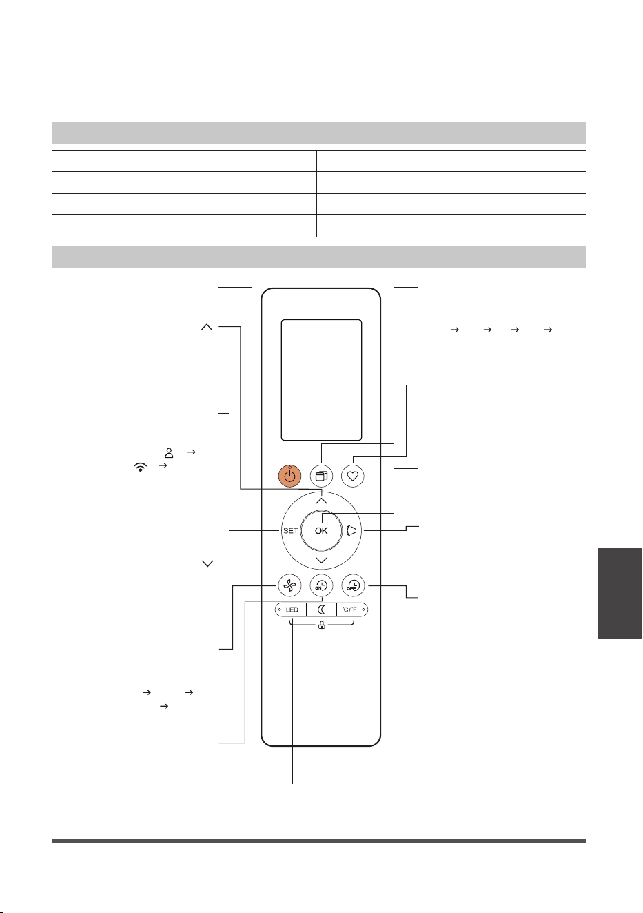
Function Buttons
Remote Control
and App
Instructions
TIMER OFF
Sets timer to turn unit off
(see How to Use Basic
Functions for instructions).
FAN SPEED
Switches the fan
speed as follows:
Auto
Low
Medium High ...
SLEEP
Saves energy during
sleeping hours.
SWING
Starts and stops the
horizontal louver
movement.
ON/OFF
Turns the unit on or off.
Turn the unit’s LED display and
control panel beeps on or off.
LED
MODE
Switches the operating
modes as follows:
Auto Cool Dry Heat Fan
TIMER ON
OK
Press to send the desired
settings to the AC unit.
TEMP
Decreases temperature
in 1°F (1°C) increments.
Min. temperature is
60°F (16°C).
TEMP
Increases temperate in
1°F (1°C) increments.
Max. temperature is
86°F (30°C).
Sets timer to turn
unit on (see How
to Use Basic
Functions for
instructions).
SET
Scrolls through operation
functions as follows:
The selected symbol will
flash on the display area,
press the OK button to
confirm.
°C/°F
Change the temperature
units between °C and °F.
SHORTCUT
Used to restore the
current settings or
resume previous settings.
Comfort sense ( )
A
sense...
P mode ( ) Comfort
Remote Control Specifications
)2x30RL/30R seirettab yrD ( V0.3egatloV detaR
)m 8( tf 62egnaR gnivieceR langiS
)F°041 ~ F°32( C° 06 ~ C° 5-tnemnorivnE
Model RG10F2(B2)/BGEFU1
BATTERY DISPOSAL
Ensure used batteries are disposed of properly.
TIPS FOR USING REMOTE CONTROL
• In order to properly transmit a command, the ON/OFF indicator must be illuminated on the remote’s
display. (See the Remote LED Screen Indicators section for more information.)
Page 24
Remote Screen Indicators
Remote Control
and App
Instructions
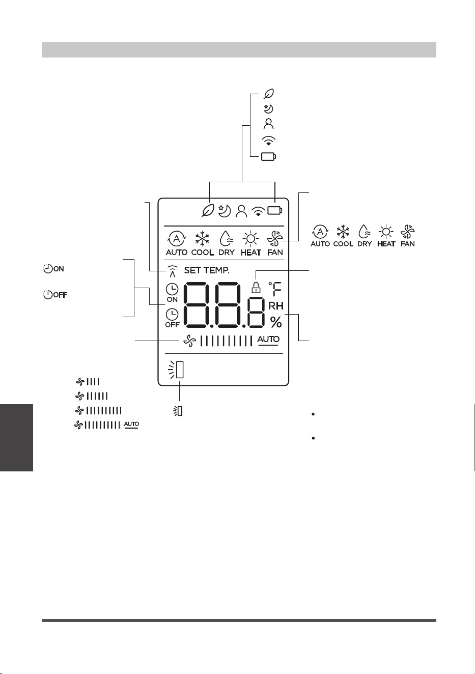
Information is displayed when the remote control is powered on.
Transmission Indicator
MODE display
FAN SPEED display
LOCK display
Temperature/Timer/
Fan speed display
Fresh feature display (Not applicable)
Sleep mode display
Comfort sense feature display
Wireless control feature display
Low battery detection display
(If flashes)
Displays when LOCK
feature is activated.
Lights up when remote
sends signal to indoor
unit.
Displays the current mode,
including:
TIMER ON display
TIMER OFF display
Displays the set temperature
by default, or fan speed or
timer setting when using
TIMER ON/OFF functions.
Temperature range:
16-30°C / 60-86°F
Timer setting range:
0-24 hours
This display is blank when
operating in FAN mode.
LOW
MED
HIGH
AUTO
Displays selected
fan speed:
This fan speed can not be
adjusted in AUTO or DRY
mode.
Horizontal louver
auto swing display
(NOT APPLICABLE)
Page 25
Remote Control
and App
Instructions
x5
1sec
xn
xnxn
x10
1sec
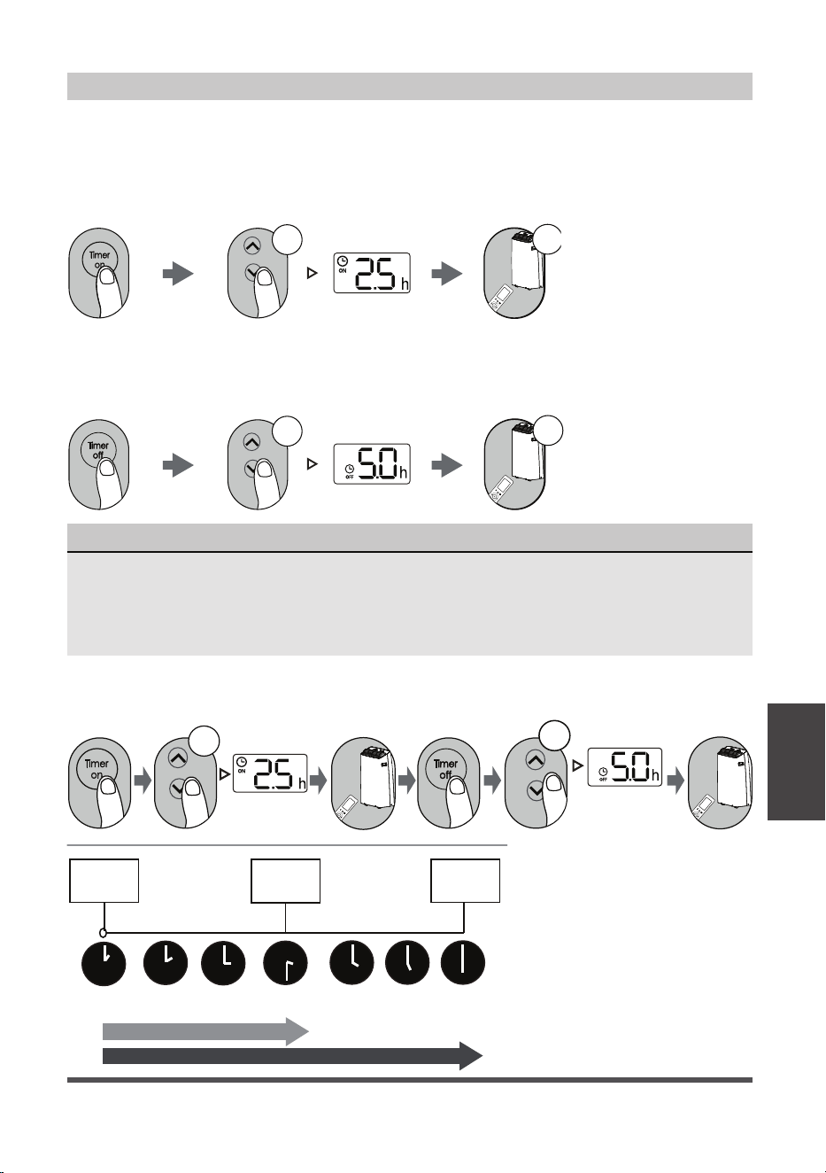
Setting the TIMER
TIMER ON SETTING
TIMER OFF SETTING
TIMER ON & OFF SETTING (EXAMPLE)
Press TIMER ON
button to initiate the
ON time sequence.
Press TIMER OFF
button to initiate the
OFF time sequence.
Keep in mind that the time periods you set for both functions refer to hours after the current time.
Example: If current timer is
1:00PM, to set the timer as
above steps, the unit will turn
on 2.5h later (3:30PM) and turn
off at 6:00PM.
Press up or down button for
multiple times to set the desired
time to turn on the unit.
Press up or down button for
multiple times to set the desired
time to turn off the unit.
Point remote to unit and wait
1 sec, the TIMER ON will be
activated.
Point remote to unit and wait
1 sec, the TIMER OFF will be
activated.
TIMER ON/OFF - Set the amount of time after which the unit will automatically turn on/off.
Current
time 1PM
2:00PM 3:00PM
4PM 5PM
6PM
Timer
starts
Unit turns
ON
Unit turns
OFF
2.5 hours later
5 hours later
3:30PM
NOTICE
1. When setting the TIMER ON or TIMER OFF, the time will increase by 30 minutes
increments with each press, up to 10 hours. After 10 hours and up to 24, it will increase in
1 hour increments. (For example, press 5 times to get 2.5h, and press 10 times to get 5h,).
The timer will revert to 0.0 after 24.
2. Cancel either function by setting its timer to 0.0h.
Page 26
We hereby declare that this AC is in compliance with the essential requirements and
other relevant provisions of Directive 1999/5/EC.
1. Supports operating systems: iOS 7+ or Android 4+.
2. In the event of a OS update, there may be a delay between the update of the OS
and a related software update during which your OS may or may not be supported
until a new version is released. Your specific mobile phone or problems in your
network may prevent the system from working and Midea will not be responsible
for any problems that could be caused by incompatibility or network issues.
3. This Smart AC only supports WPA-PSK/WPA2-PSK (recommended) encryption.
4. To ensure proper scanning of the QR code, your smart phone must have at least a
5-megapixel camera.
5. Due to unstable network connectivity, requests may time out. If this happens, re-
run the network configuration.
6. Due to unstable network connectivity, commands may time out. If this happens,
the smartphone app and the actual product may display conflicting information.
The information displayed on the actual product is always the most accurate
available. Refresh the app to re-sync.
Model: US-SK105 Dimensions: 41 x 24 x 5 (mm)
Operation Temperature: 0°C ~ 45°C / 32°F ~ 113°F.Standard: IEEE 802.11 b/g/n
Antenna Type: Printed PCB
Antenna
Operation Humidity: 10% ~ 85%
Power Input: DC 5V/300 mAFrequency: 2400-2483.5MHz
Maximum Transmitted Power:
<20 dBm Max
Midea will not be responsible for any problems that could be caused by
incompatibility or network issues, your wireless router and mobile phone.
NOTICE
DECLARATION OF CONFORMITY
SPECIFICATION OF WIRELESS MODULE
PRECAUTIONS
Remote Control
and App
Instructions
Page 27
Remote Control
and App
Instructions
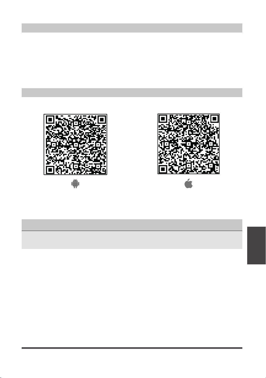
Devices required to use the Smart AC:
1. Smart Phone with compatible iOS or Android system.
2. Wireless Router (a 2.4GHz network is required to connect).
3. Smart Air Conditioner
Android QR code Apple QR code
Scan to download app.
• You can also go to Google Play or App Store and search for Midea Air.
DOWNLOAD AND INSTALL THE APP
SYSTEM OVERVIEW
NOTICE
All the images in this manual are for reference only, your product and app may look
slightly different. The actual product and app instructions have to be considered.
Page 28
• Make sure your smartphone is connected to your wireless router and your wireless
router has a working 2.4GHz internet connection.
• It is recommended to activate your account immediately to be able to recover your
password by email.
NOTICE
• Make sure your smartphone is able to connect to the wireless network which will be used.
• Make sure also that the device is not connecting to other networks in range.
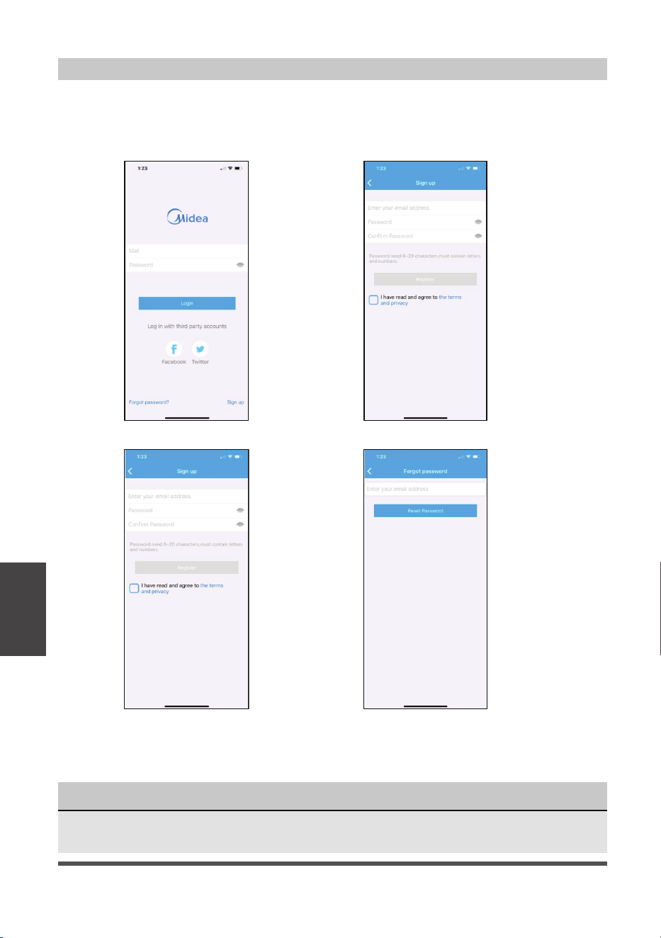
CREATE YOUR ACCOUNT
1. Press “Sign Up”. 2. Enter your email address and password.
3. Press “Registration”. 4. If you forget your password, press
“Forgot password?” on the main
menu and enter your email address.
Then press “Reset Password”.
Remote Control
and App
Instructions

Page 29
Remote Control
and App
Instructions
ADDITIONAL APP AND SMART HOME FUNCTIONS
For additional instructions regarding the features of the app and Smart Home skill
capabilities, scan the QR code below.

Page 30
Air Conditioner Limited Warranty
Your product is protected by this Limited Warranty:
Warranty service must be obtained from Midea Consumer Services or an authorized Midea servicer.
Warranty
• One year full warranty from original purchase date.
Midea, through its authorized servicers will:
• Pay all costs for reparing or replacing parts of this appliance which prove to be defective in materials
or workmanship.
Consumer will be responsible for:
• Diagnostics, removal, transportation and reinstallation cost required because of service.
• Costs of service calls that are a result of items listed under NORMAL RESPONSABILITIES OF THE CONSUMER**
Midea replacement parts shall be used and will be warranted only for the original warranty.
NORMAL RESPONSABILITIES OF THE CONSUMER**
This warranty applies only to products in ordinary household use, and the consumer is responsible for
the items listed below:
1. Proper use of the appliance in acordance with instructions provided with the product.
2. Routine maintenance and cleaning necessary to keep the good working condition.
3. Proper installation by an authorized service professional in accordance with instructions provided with the
appliance and in accordance with all local plumbing, electrical and/or gas codes.
4. Proper connection to a grouded power supply of sufficient voltage, replacement of blown fuses, repair of
loosen connections or defects in house wiring.
5. Expenses for making the appliance accessible for servicing.
6. Damages to finish after installation.
EXCLUSIONS
This warranty does not cover the following:
1) Failure caused by damage to the unit while in your possesion (other than damage caused by
defect or malfunction), by its improper installation, or by unreasonable use of the unit, including
without limitation, failure to provide reasonable and necessary maintenance or to follow the written
installation and Operating Instructions.
2) Damages caused by services performed by persons other than those authorized by Midea customer
service; or external causes such as abuse, misuse, inadequate power supply or acts of God.
3) If the unit is put to commercial, business, rental, or other use or application other than for consumer
use, we make no warranties, express or implied, including but not limited to, any implied warranty of
merchantability or fitness for use or purpose.
4) Products without original serial numbers or products that have serial numbers which have been altered
or cannot be readily determined.
NOTICE: Some states do not allow the exclusions or limitation of incidental or consequential damages.
So this limitation or exclusion may not apply to you.
IF YOU NEED SERVICE
Keep your bill of sale, delivery slip, or some other appropriate payment Record.
The date on the bill establishes the warranty period, should service be required.
If service is performed, its your best interest to obtain and keep all receipts.
This written warranty gives you specific legal rights. You may also have other rights that vary from state to state.
Service under this warranty must be obtained by following these steps, in order:
1) Contact Midea Consumer Services or an authorized Midea services at 1 866 646 4332.
2) If there is a question as to where to obtain service, contact our consumer relations Departament.
WARRANTY
Warranty


WARNING: Chemical Burn Hazard. Keep batteries away from children.
This product contains a lithium button/coin cell battery. If a new or used lithium button/coin cell battery is
swallowed or enters the body, it can cause severe internal burns and can lead to death in as little as 2 hours.
Always completely secure the battery compartment. If the battery compartment does not close securely,
stop using the product, remove the batteries, and keep it away from children. If you think batteries might
have been swallowed or placed inside any part of the body, seek immediate medical attention.