Page 1
709-3912
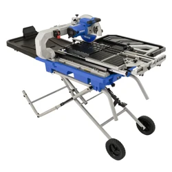
10" Sliding Tile Saw
OPERATOR’S MANUAL
CAUTION: To Reduce The Risk Of Injury, User Must Read
And Understand Operator’s Manual. Save These Instructions
For Future Reference.
For questions / comments, technical assistance or repair
parts - Please call toll free at: 1-877-684-8912 (Monday -
Friday 8am - 6pm EST.)

TABLE OF CONTENTS
Safety Symbols ............................................................................................................................................................
Safety Instructions .......................................................................................................................................................
Overview ......................................................................................................................................................................
Specications ..............................................................................................................................................................
Contents ....................................................................................................................................................................
Assembly ...................................................................................................................................................................
Operation ...................................................................................................................................................................
Maintenance ..............................................................................................................................................................
Troubleshooting .........................................................................................................................................................
Replacement parts list ...............................................................................................................................................
Warranty......................................................................................................................................................................
Page 2
Page 3
Page 8
Page 9
Page 10
Page 11
Page 22
Page 28
Page 30
Page 31
Page 32
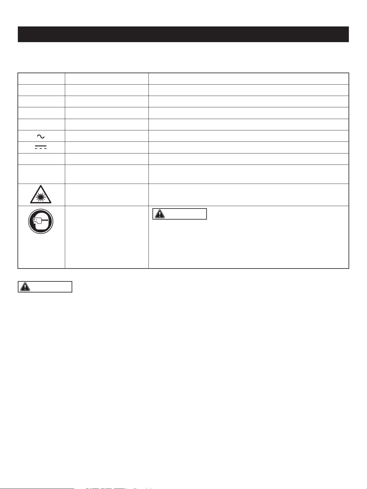
Some of these following symbols may be used on this tool. Please study them and learn their meaning. Proper interpretation
of these symbols will allow you to operate the tool better and safer.
SAFETY SYMBOLS
Page 2
WARNING: The operation of any power tool can result in
foreign objects being thrown into your eyes, which can result in severe
eye damage. Before beginning power tool operation, always wear
safety goggles or safety glasses with side shields and a full-face shield
when needed. We recommend a Wide Vision Safety Mask for use over
eyeglasses or standard safety glasses with side shields. Always use
eye protection which is marked to comply with ANSI Z87.1.
Symbol Name Designation / Explanation
V Volts Voltage
A Amperes Current
Hz Hertz Frequency (cycles per second)
W Watts Power
Alternating current Type of current
Direct current Type of characteristic of current
no No-load speed Rotational speed at no load
.../min
Per minute Revolutions, strokes, surface speed orbits, etc., per minute
Wear safety goggles
Laser radiation Do not stare into beam or view directly with optical instruments
WARNING: To ensure safety and reliability, all repairs should be performed by a qualied service technician.
The purpose of safety symbols is to attract your attention to possible dangers. The safety symbols and the explanations
with them deserve your careful attention and understanding. The symbol warnings do not, by themselves, eliminate any
danger. The instructions and warnings they give are no substitutes for proper accident prevention measures.
SAFETY INSTRUCTIONS
Page 3
WARNING: Be sure to read and understand all safety instructions in this manual, including all safety alert symbols
such as “DANGER,” “WARNING,” and “CAUTION” before using this tool. Failure to follow all instructions listed below may
result in electric shock, re, and/or serious personal injury.
WARNING: Indicates a potentially hazardous situation, which, if not avoided, could result in death
or serious injury.
CAUTION: Indicates a potentially hazardous situation, which, if not avoided, could result in minor or moderate
injury.
DANGER: Indicates an imminently hazardous situation, which, if not avoided, will result in death or serious injury.
SYMBOL MEANING
SAFETY ALERT SYMBOL: Indicates DANGER, WARNING, OR CAUTION. May be used in conjunction with
other symbols or pictographs.
NOTICE: (Without Safety Alert Symbol) Indicates a situation that may result in property damage.
SAVE THESE INSTRUCTIONS!

Please read and understand this entire manual before
attempting to assemble, operate, or install the tile saw.
This manual contains information that relates to PROTECTING
PERSONAL SAFETY and PREVENTING EQUIPMENT
PROBLEMS. It is very important to read this manual carefully
and understand it thoroughly before using the tile saw.
SAFETY RECOMMENDATIONS
These precautions are intended for the personal safety of
the operator and others working with the operator. Failure
to follow these instructions may result in a permanent loss
of vision, serious personal or even fatal injury, property
damage and/or tool damage. Please take time to read and
understand them. Safety is a combination of common sense,
staying alert and knowing how your tile saw works.
BEFORE USE
• For safe handling of this tile saw, the user must have read
and understood the instructions for use before using it for
the rst time.
• Observe all safety instructions! If you DO NOT observe
the safety instructions, you will endanger yourself and
others.
• Keep all instructions for future reference.
• Attach the instructions for use, if you pass on the tile saw
to someone else.
• KEEP WORK AREA CLEAN. Cluttered areas and benches
invite accidents.
• All parts of the tile saw, safety devices in particular, must
be correctly installed to ensure faultless operation.
OPERATION/WORKPLACE
• KEEP GUARDS IN PLACE and in working order.
• REMOVE ADJUSTING KEYS AND WRENCHES. Form
habit of checking to see that keys and adjusting wrenches
are removed from the tile saw before turning it on.
• KEEP CHILDREN AWAY. All visitors should be kept at a
safe distance from work area.
• MAKE WORKSHOP CHILDPROOF with padlocks, master
switches or by removing starter keys.
• DO NOT FORCE TILE SAW. It will do the job better and
safer at the rate for which it was designed.
• USE THE RIGHT TILE SAW. DO NOT force tile saw or
attachments to do a job for which it was not designed.
• DO NOT OVERREACH. Keep proper footing and balance
at all times.
• REDUCE THE RISK OF UNINTENTIONAL STARTING.
SERVICE
• DISCONNECT TILE SAW before servicing or when changing
accessories, such as tile saw blade.
• Have your tile saw repaired only by qualied technicians,
using only genuine spare parts. This will maintain the safety
of the tile saw.
• DO NOT USE IN A DANGEROUS ENVIRONMENT. DO
NOT use power tools in damp or wet locations, or expose
them to rain. Keep work area well lit.
• MAINTAIN TILE SAW WITH CARE. Maintain sharp tile saw
blade and clean the tile saw for best and safest performance.
• Follow instructions for lubricating and changing accessories.
• A tile saw blade can cause injuries, even when stationary!
Use protective gloves to change the tile saw blade.
• NEVER use lateral counter pressure to bring the tile saw
blade to a standstill after switching off the tile saw.
• Replace table insert when worn.
• Use only diamond tile saw blades recommended by the
Make sure switch is in the off position before plugging in.
• DIRECTION OF FEED. Feed work into a tile saw blade
against the direction of rotation of the tile saw blade only.
• NEVER LEAVE TOOL RUNNING UNATTENDED. TURN
POWER OFF. DO NOT leave tile saw before it comes to
a complete stop.
• The tile saw may be used only when in a good working
condition. If the tile saw or part of the tile saw is defective,
have it repaired by an expert.
• ALWAYS follow the applicable national and international
safety, health and labor regulations.
• The tile saw may only be used if no defects are found
during the inspection. Ensure that any defective parts are
replaced before the tile saw is used again.
• Position the tile saw horizontally on a rigid, even surface
with adequate load-bearing capacity.
• DO NOT leave any tools, objects, or cables lying in the
working range of the tile saw.
• Ensure that there is sufcient lighting during operation.
• Assume a natural and secure stance when working.
• Make sure that during operation, no body parts or clothing
are caught and drawn in by rotating components.
• The immediate environment must be free of combustible
and other ammable or explosive substances.
• Young people under 18 years of age and users who are
not sufciently familiar with its operation must not use the
tile saw.
• Persons unable to safely and carefully use the tile saw for
any reason must not use the tile saw.
• Work with caution. Do not operate this tile saw if you are
fatigued, ill, or are under the inuence of alcohol, medication
and/or drugs.
SAFETY INSTRUCTIONS
Page 4
WARNING: To avoid mistakes that could cause
serious injury, DO NOT plug in the tile saw until you have
read and understood the rules.
STORAGE AND TRANSPORT
• ALWAYS store the tile saw in a dry place.
• Store the tile saw in a frost-free place.
• Protect the tile saw from damage during transport.
• Keep the tile saw away from children. Store the tile saw
in a place where it is safe from children and unauthorized
persons.
USE DUST MASK
Some dust created by sawing contains chemicals that are
known to cause cancer, birth defects or other reproductive
harm. To reduce exposure to these chemicals, work in a
well-ventilated area with approved safety equipment, such
as dust masks that are specially designed to lter out
microscopic particles.
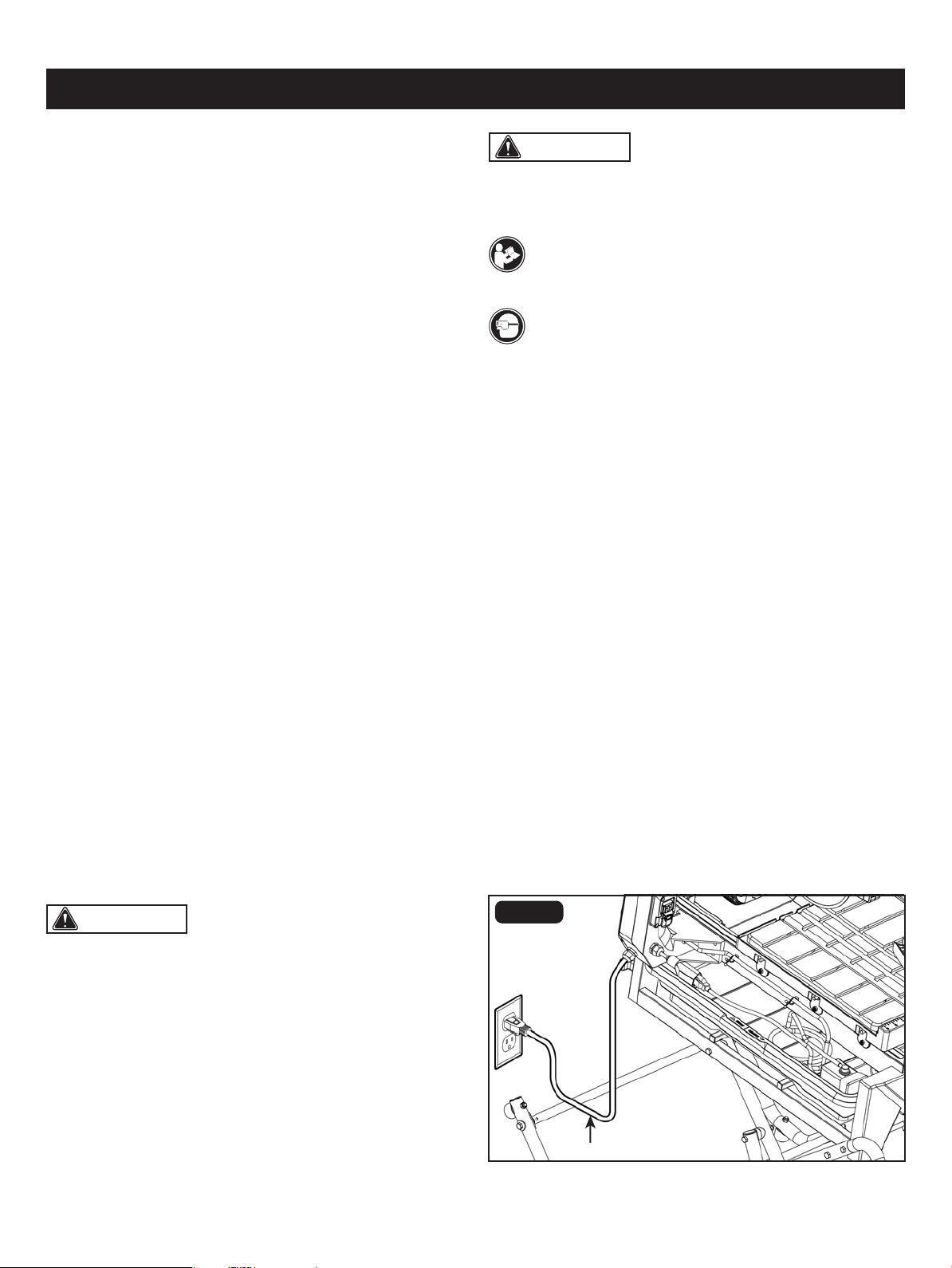
POSITION OF TILE SAW
• To avoid the possibility of the appliance plug or receptacle
getting wet, position tile saw to one side of a wall-mounted
receptacle to prevent water from dripping onto the
receptacle or plug. The user should arrange a "drip loop"
in the cord connecting the saw to a receptacle. The "drip
loop" is the part of the cord below the level of the
receptacle, or the connector if an extension cord is used,
to prevent water traveling along the cord and coming into
contact with the receptacle.
• If the plug or receptacle does get wet, DO NOT unplug
the cord. First, disconnect the fuse or circuit breaker that
supplies power to the tile saw. Then unplug and examine
for presence of water in the receptacle.
INJURY RISKS
Even when the tile saw is used properly and in compliance
with all the safety precautions in these instructions, the
following residual risks can arise:
• Touching the tile saw blade in the exposed area.
• Reaching into the spinning tile saw blade.
• Ejection of cut pieces.
• Serious injury resulting from failure to wear required safety
protection.
manufacturer.
• Use only diamond tile saw blades for which the maximum
possible speed is not less than the maximum spindle
speed of the tool and the material to be cut.
• Maximum size of working piece should be 24" length and
24.5" width.
• This tile saw should be used at an ambient temperature
between 59-80°F (15-50°C).
• USE PROPER EXTENSION CORD. Make sure your
extension cord is in good condition. When using an
extension cord, be sure to use one heavy enough to carry
the current your product will draw. An undersized cord will
cause a drop in line voltage, resulting in loss of power and
overheating. The chart on Page 6 shows the correct size
to use depending on cord length and nameplate ampere
rating. If in doubt, use the next heavier gauge. The smaller
the gauge number, the heavier the cord.
SAFETY INSTRUCTIONS
READ OPERATOR’S MANUAL
To reduce the risk of injury, user must read and
understand operator’s manual before using this tile saw.
Page 5
WARNING: For your own safety, read instruction
manual before operating tile saw.
WARNING: The tile saw is loud and the sound can
cause hearing damage. ALWAYS wear ear protection to
help prevent hearing damage and loss. Failure to comply
may result in injury.
FIG. 1
• Wear eye protection.
• Use splash guard for every operation for which it can be
used.
• Disconnect tile saw before servicing, when changing tile
saw blades, and cleaning.
• Use tile saw only with diamond tile saw blades.
• Replace damaged tile saw blade before operating.
• DO NOT ll water tank above water ll line.
• USE SAFETY GOGGLES AND EAR PROTECTION
• ALWAYS WEAR EYE PROTECTION THAT CONFORMS
WITH UL REQUIREMENTS. FLYING DEBRIS can cause
permanent eye damage.
Drip loop
Grounding
Plug
Metal
Screw
Cover Of
Grounded
Outlet Box
Adaptor
Grounding
Means
(A)
Circuit and Adapter Information
Grounding
Plug
(D)
(B)
(C)
SAFETY INSTRUCTIONS
Page 6
WARNING: In case of a malfunction or breakdown,
grounding provides a path of least resistance for electric
current to reduce the risk of electric shock. This tile saw
is equipped with an electric cord having an equipment-
grounding conductor and a grounding plug. The plug must
be plugged into a matching outlet that is properly installed
and grounded in accordance with all local codes and
ordinances.
WARNING: Use of a temporary adapter is not
permitted in Canada.
FIG. 2
GROUND INSTRUCTION
In order to prevent potential electrical shock and injury, the
following electrical safety precautions and symbols should
be followed at all times!
PERMANENTLY CONNECTED TOOLS
This tile saw can be permanently connected to a grounded,
metal, wiring system or to a system that has an equipment-
grounding conductor.
Ground-fault circuit interrupter (GFCI) protection should be
provided on the circuit or outlet to be used for the tile saw.
Receptacles are available having built-in GFCI protection
and may be used for this measure of safety.
GUIDELINES FOR EXTENSION CORDS
Use a proper extension cord. Make sure extension cords
are in good condition. When using an extension cord, be
sure to use a cord that is heavy enough to carry the drawn
current needed by the saw. An undersized cord will cause
a drop in line voltage, resulting in loss of power and
overheating.
• Do not modify the plug provided – if it will not t the outlet;
have the proper outlet installed by a qualied electrician.
• Improper connections of the equipment-grounding
conductor can result in a risk of electric shock. The
equipment-grounding conductor is the insulated conductor
that has an outer surface that is green, with or without
yellow stripes. If repair or replacement of the electric cord
or plug is necessary, do not connect the equipment-
grounding conductor to a live terminal
• Check with a qualied electrician or service personnel if
the grounding instructions are not completely understood,
or if in doubt as to whether the tile saw is properly grounded.
• Use only 3-wire extension cords that have 3-prong
grounding plugs and 3-pole receptacles that accept the
tile saw’s plug.
• Repair or replace a damaged or worn cord immediately.
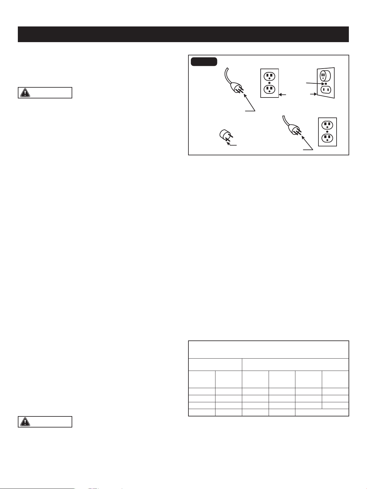
Grounded, cord-connected tools intended for use on a
supply circuit having a nominal rating less than 150 Volts:
• This tile saw is intended for use on a circuit that has an
outlet that looks like the one shown in Sketch A of Figure 2.
The tile saw has a grounding plug that looks like the plug
illustrated in Sketch A of Figure 2.
• A temporary adapter, which looks like the adapter
illustrated in sketches B and C, may be used to connect
this plug to a 2-pole receptacle as shown in Sketch B, if
a properly grounded outlet is not available. The temporary
adapter should be used only until a properly grounded
outlet can be installed by a qualied electrician. The
greencolored rigid ear, lug, and the like, extending from
the adapter, must be connected to a permanent ground
such as a properly grounded outlet box.
The table below shows the correct size to use, depending
on the cord length and nameplate amperage rating. If
in doubt, use the next heavier gauge. The smaller the gauge
number, the heavier the cord.
Be sure extension cords are properly wired and in good
condition. Always replace a damaged extension cord
or have it repaired by a qualied technician before using it.
Protect extension cords from sharp objects, excessive heat,
and damp or wet areas.
MINIMUM GAUGE (AWG)
EXTENSION CORDS (120V use only)
Amperage rating
Total length
Not Recommended
Not more
than
25'
(7.5 m)
6 18
50'
(15 m)
16
100'
(30 m)
16
150'
(45 m)
14
More
than
0
10 18 16 14 126
12 16 16 14 1210
16 14 1212
SAFETY INSTRUCTIONS
Page 7
• Bevel Lock Lever: The bevel lock lever securely locks
the saw head at 0°, 45°, and 22.5° bevel angles.
• Mitre Guide: The easy-to-read indicator on the mitre guide
shows the exact angle for a mitre cut with detents at 0°,
22.5° and 45°.
• ON/OFF Switch - This tile saw has an easy-access power
switch located on the tile saw arm.
• Table - The table allows the user to slide the workpiece
into the tile saw blade for accurate cuts.
• Water Pump: The water pump provides water to the tile
saw blade or cleaning nozzle.
• Water Tray: Using the water pump and water tray together
keeps water circulating to the tile saw eliminating the need
for frequent water changes.
• Toggle Table Stop: This allows the table to be removed
if needed. Lift the stop and turn it to lock/unlock. If the
slot is aligned with table, the table can be removed. If the
slot is turned sideways, the table is locked into the tile saw.
• Table Lock Lever: To lock the table in place, line up this
lever’s pin with the hole in the rail, and press the lever
towards the rail. Pull out on the lever to unlock the table.
• Tool Storage: The arbour nut wrench and hex key are
conveniently stored on the back of the tile saw arm.
Be sure extension cords are properly wired and in good
condition. Always replace a damaged extension cord
or have it repaired by a qualied technician before using it.
Protect extension cords from sharp objects, excessive heat,
and damp or wet areas.
WARNING: Keep the extension cord clear of the
working area. Position the cord so that it will not get caught
on lumber, tools, or other obstructions while you are working
with a tile saw. Failure to do so can result in serious
personal injury.
WARNING: Check extension cords before each
use. If damaged replace immediately. Never use tile saw with
a damaged cord since touching the damaged area could
cause electrical shock resulting in serious injury.
WARNING: Do not use diamond tile saw blade
rated less than the speed of this tile saw. Failure to heed
this warning could result in personal injury.
WARNING: To avoid electrical hazards, re hazards,
or damage to the tile saw, use proper circuit protection.
Use a separate electrical circuit for power tools. This circuit
should be protected with a time delayed fuse. Before
connecting the tile saw to the power line, make sure the
switch is in the OFF position and the electric current is rated
the same as the current stamped on the motor’s nameplate.
Running at a lower voltage will damage the motor.
GLOSSARY OF TERMS
The safe use of this tile saw requires an understanding of
the information on the tile saw from this operator’s manual
as well as a knowledge of the project you are attempting.
Before use of this tile saw, familiarize yourself with all
operating features and safety rules.
• Saw Blade: Use only 10 in. diamond tile saw blade.
Page 8
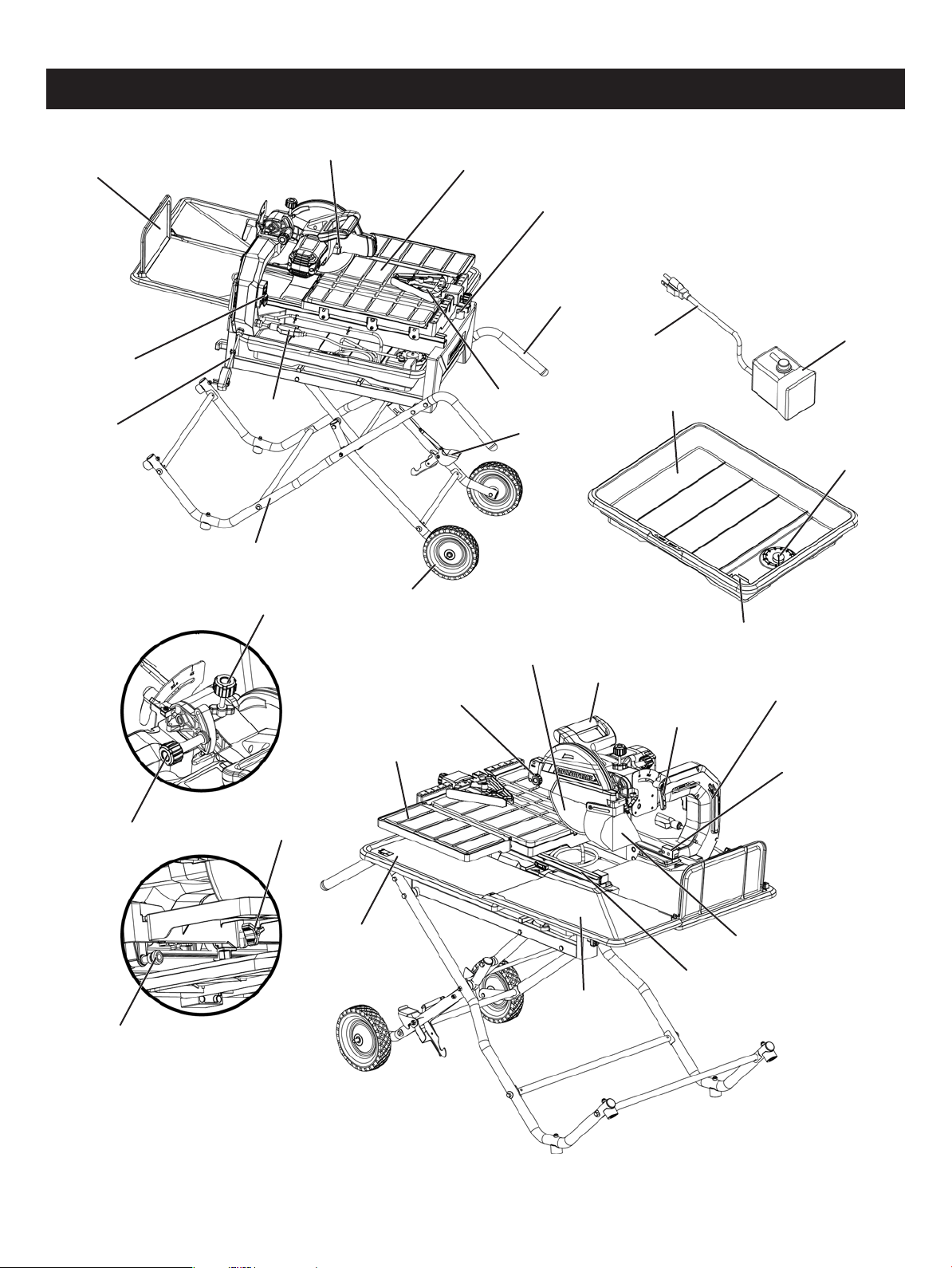
OVERVIEW
Blade lock knob
Miter gauge
Release lever
Stand
Pump outlet
Roller wheel
Pump power cord
Water pump
Water tray
Pump bracket
Drain plug
Depth lock knob
Lock knob
for extension table
Extension table
Handle
Saw blade
Bevel lock lever
Tool storage
Table stop
Guard lock knob
Lock knob
for head
Table lock lever
Side extension
tray A
Side extension
tray B
Water tray
frame
Splash guard
Stand handle
Table
Power cord
ON/OFF Switch
Toggle table stop
Rear extension tray

Page 9
Motor
No load speed
Diamond tile saw blade
Maximum depth of cut
Rip capacity (tile size)
4500 RPM
120 V~ 60 Hz 15A
10 in. x 5/8 in. (arbor)
3-3/4 in.
24 in.
Diagonal Capacity (tile size) 18 in.
0°, 22.5°, 45°
Bevel cut range
SPECIFICATIONS
Page 10
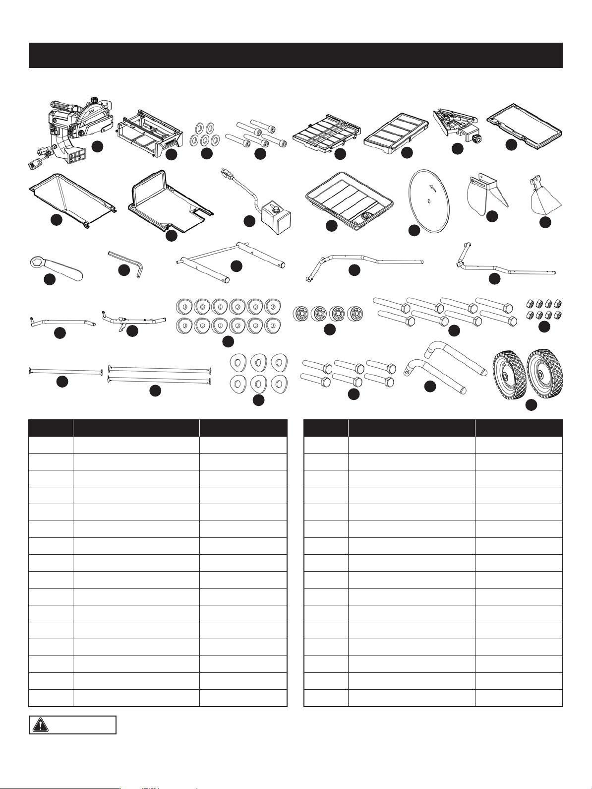
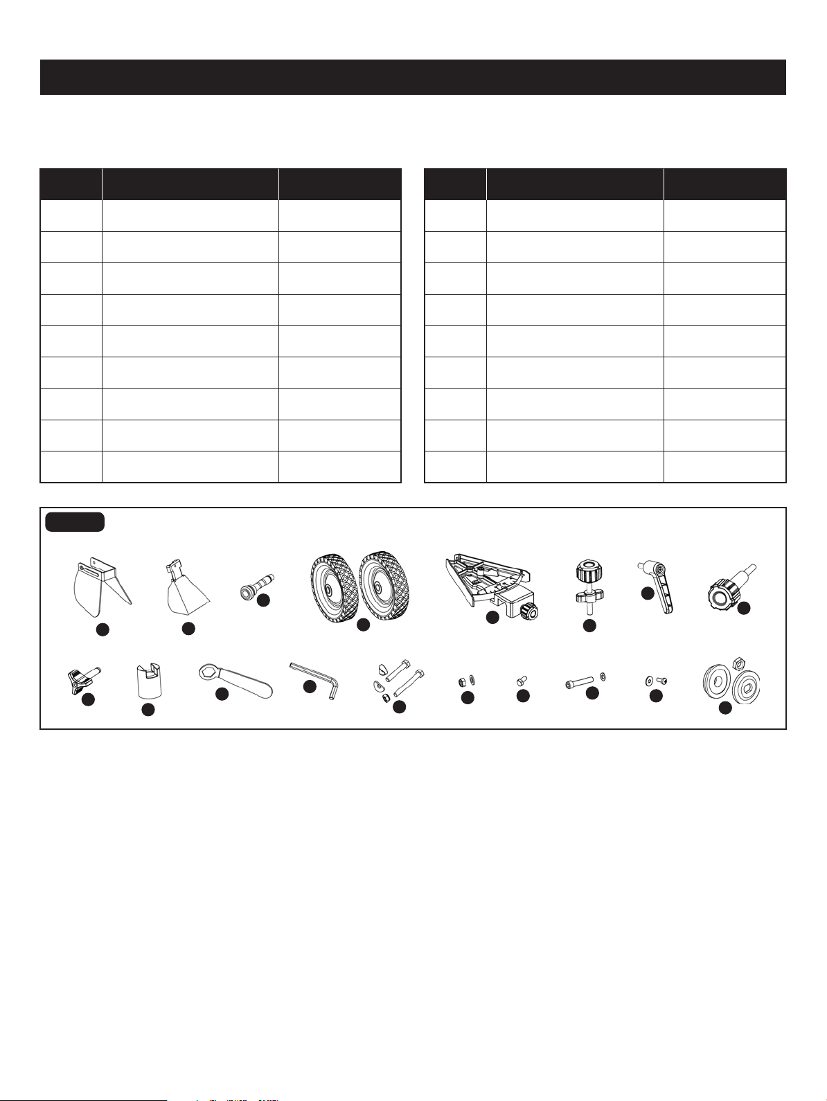
CONTENTS
WARNING: The use of attachments or accessories not listed in this manual might be hazardous and could cause
serious personal injury.
A 1
B 1
C 5Flat Washer 10
Water Tray Frame Assembly
Motor Head Assembly
The following items are included with your 10" Sliding Tile Saw:
A
B
C
D
E
F
H
I
J
K
L
M
N
O
P
Q
S
R
U
AA
BB
CC
DD
FF
EE
V
W
X
Y
Z
T
G
PART DESCRIPTION QUANTITY
1
R
Q 8mm Hex Key
1Upper Stand Assembly
1S Stand Leg A
D 5Hex cap screw M10 x 52
1T Stand Leg B
E 1Table
1U Roller Stand Leg A
F 1Extension Table 1V Roller Stand Leg B
G 1Miter Gauge 12W Spacer
4Flat Spacer
H 1Side Extension Tray A
8
X
Hex Bolt M8 x 85I 1Side Extension Tray B
8
Y
Lock Nut M8J 1Rear Extension Tray
1
Z
Horizontal Support AK 1Water Pump
Water Tray
2
AA
Horizontal Support B
L 1
Diamond tile saw blade
6
BB
Curved Washer
M 1
Side Splash Guard
6
CC
Hex Bolt M8 x 50N 1
Rear Splash Guard
2
DD
EE Stand HandleO 1
Arbour Nut Wrench
P 1 FF 2Roller Wheel
PART DESCRIPTION QUANTITY
(ITEMS NOT SUPPLIED)
Star-head screwdriver
(ITEMS SUPPLIED)
8mm Hex key (1 pc)
Arbour nut wrench (1 pc)
UNPACKING
YOU WILL NEED
• Carefully lift the tile saw from the carton and place on a level work surface.
• Inspect the tile saw carefully to make sure no breakage or damage occurred during shipping.
• Do not discard the packing material until you have carefully inspected and satisfactorily operated the tile saw.
• The tile saw is factory set for accurate cutting. After assembling it, check for accuracy. If shipping has inuenced the
settings, refer to specic procedures explained in this manual.
WARNING: Do not use this tile saw if any parts on the Loose Parts List are already assembled to your tile saw
when you unpack it. Parts on this list are not assembled to the tile saw by the manufacturer and require customer installation.
Use of a tile saw that may have been improperly assembled could result in serious personal injury.
WARNING: If any parts are damaged or missing do not operate this tile saw until the parts are replaced. Use of
this tile saw with damaged or missing parts could result in serious personal injury.
WARNING: Do not attempt to modify this tile saw or create accessories not recommended for use with this tile
saw. Any such alteration or modication is misuse and could result in a hazardous condition leading to possible serious
personal injury.
WARNING: Do not connect to power supply until assembly is complete. Failure to comply could result in accidental
starting and possible serious personal injury.
Page 11
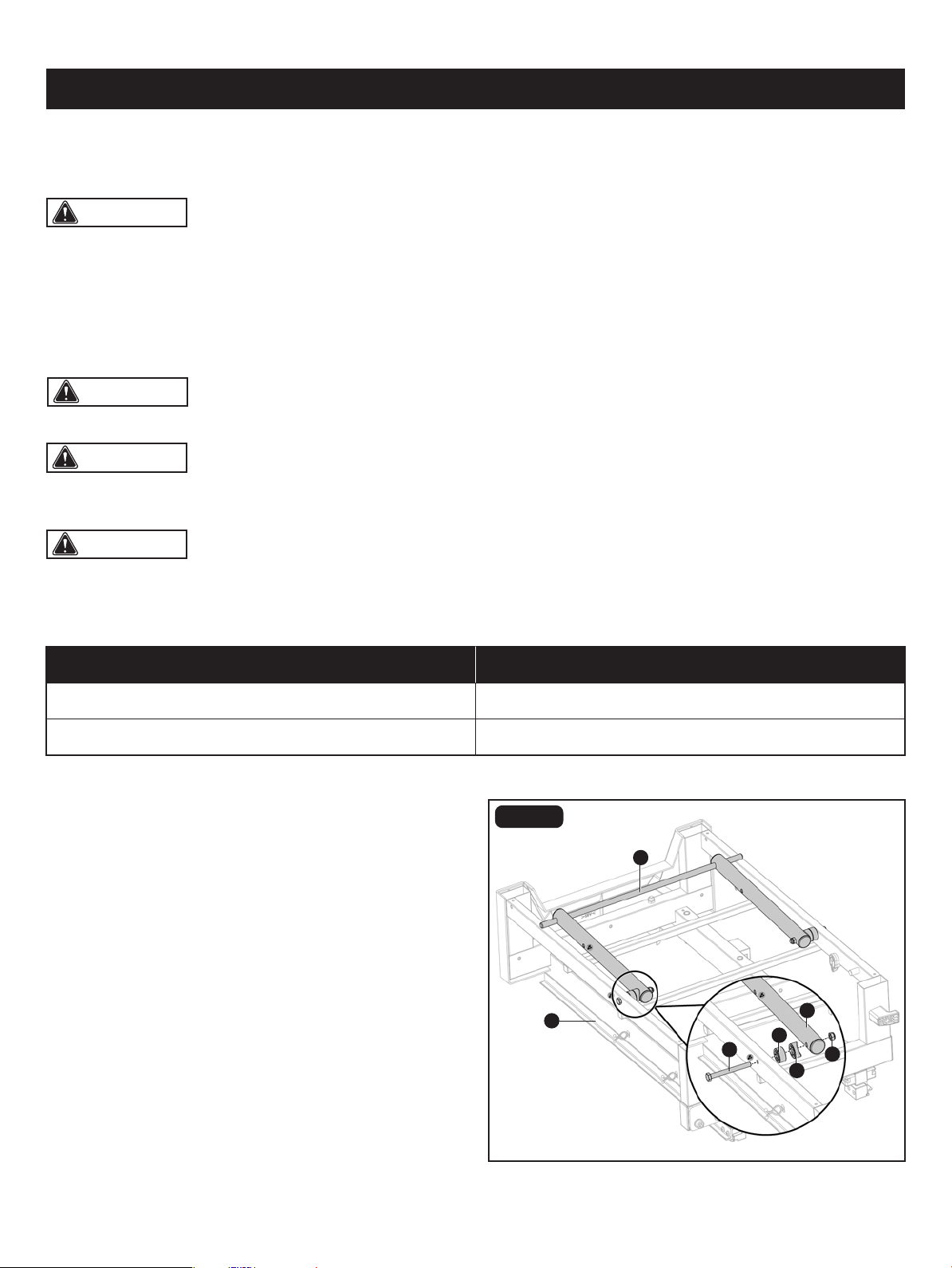
ASSEMBLY
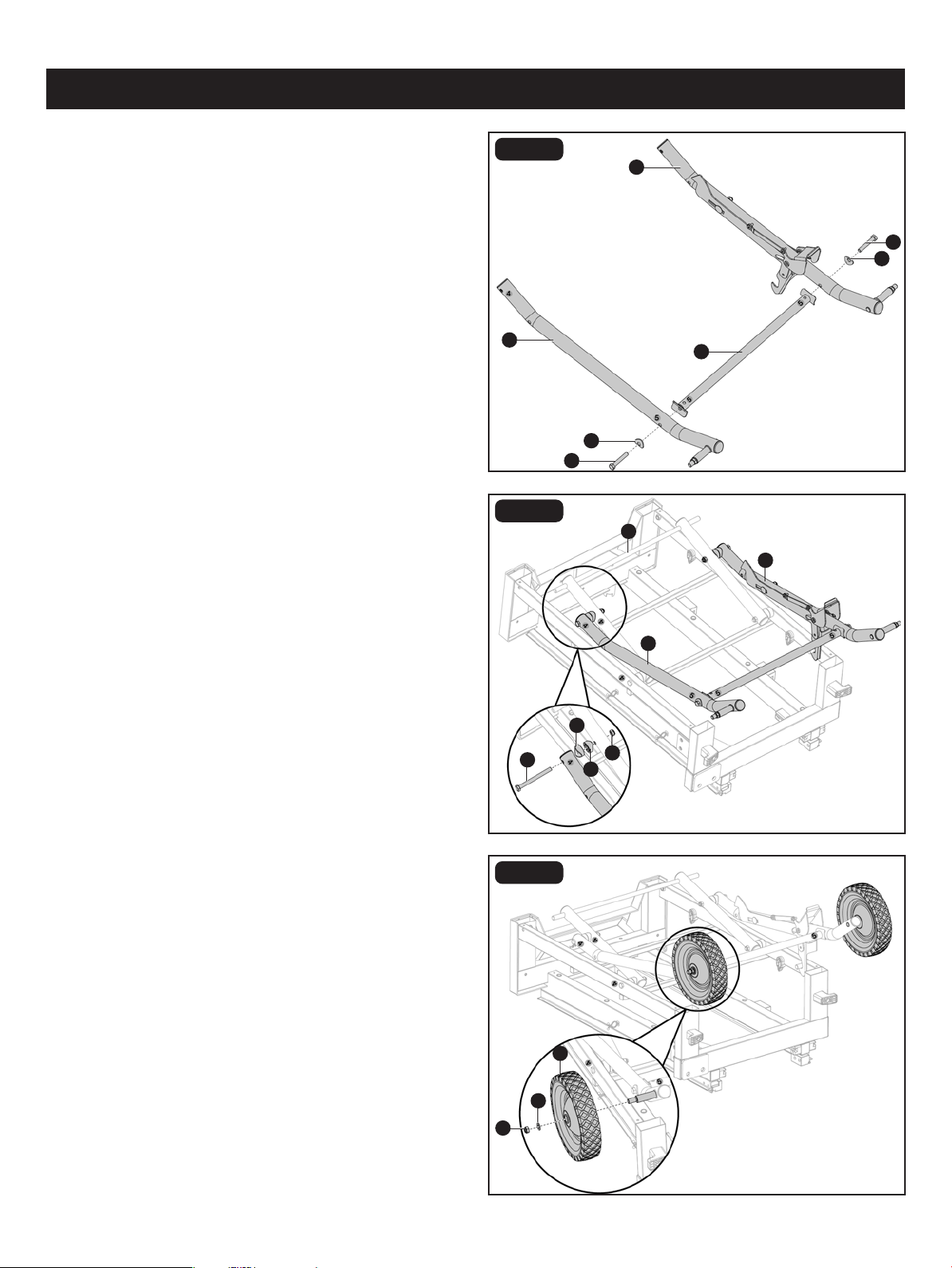
FIG. 3A
INSTALLING STAND ASSEMBLY TO
WATER TRAY FRAME ASSEMBLY
(Fig. 3A-3J)
• Place the water tray frame assembly upside down.
• Attach upper stand assembly (R) with water tray frame
assembly (B) with hex bolts M8 x 85 (Y), at spacers (X),
spacers (W) and lock nuts M8 (Z).
Y
13mm,16mm Open-end wrench or adjustment wrench
R
X
R
Z
W
B
Page 12
ASSEMBLY
FIG. 3B
FIG. 3C
FIG. 3D
• Attach roller stand leg A (U) and roller stand leg B
(V) assembly wit upper stand assembly (R) with hex bolts
M8 x 85 (Y), spacers (W) and lock nuts M8 (Z).
• Remove lock nut M10 (GG) and at washer 10 (HH)
preassembled to roller stand leg A and roller stand leg B
from each axle.
• Slide roller wheel (FF) and at washer 10 (HH) onto axle of
rollar stand leg A. Secure with lock nut M10 (GG) . Repeat
for remaining roller wheel.
• Attach the roller stand leg A (U) and roller stand leg B (V)
with horizontal support A (AA) using curved washers (CC)
and hex bolts M8 x 50 (DD).
V
U
DD
CC
AA
HH
FF
GG
U
R
V
Y
W
W
Z
DD
CC
Page 13
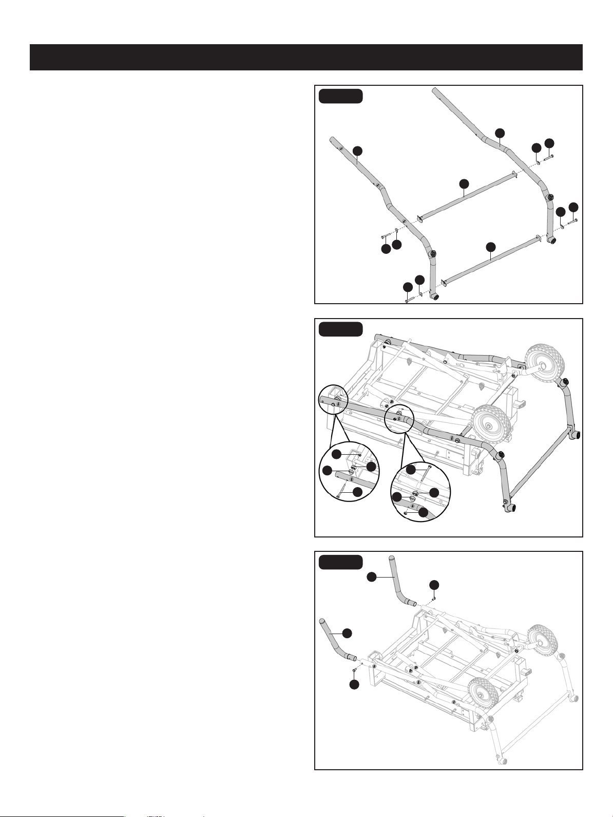
ASSEMBLY
FIG. 3F
FIG. 3G
• Attach stand A and stand B assembly to the roller stand
leg A and roller stand leg B assembly, and water tray frame
assembly with hex bolts M8 x 85 (Y), at spacers (X),
spacers (W) and lock nuts M8 (Z).
• Loosen and remove hex bolt M8 x 16 (II) preassembled to
stand handle (EE).
• Attach stand handles (EE) to stand assembly. Secure with
hex bolt M8 x 16 (II).
FIG. 3E
• Attach the stand leg A (S) and stand leg B (T) with two
horizontal supports B (BB) using curved washers (CC) and
hex bolts M8 x 50 (DD).
Z
X
EE
Y
W
S
T
BB
BB
DD
CC
II
DD
CC
CC
DD
DD
CC
II
Y
X
W
Z
EE
Page 14
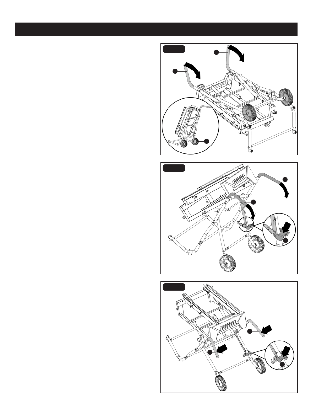
ASSEMBLY
FIG. 3H
• Grasp the stand handles (EE) and tilt stand and frame
assembly back onto roller wheels (FF) until the stand is
balanced on the wheels and stand support assembly.
FIG. 3I
FIG. 3J
• Step on the release lever (JJ) and pull the stand handles
(EE) toward you at the same time. Once the stand is released
from the release lever, ease the stand toward the oor by
pushing the stand handles toward the oor.
• With your hands on the stand handles (EE), push the stand
toward the ground until the stand is in an open position.
I
B
EE
EE
FF
EE
EE
JJ
JJ
EE
EE
Page 15
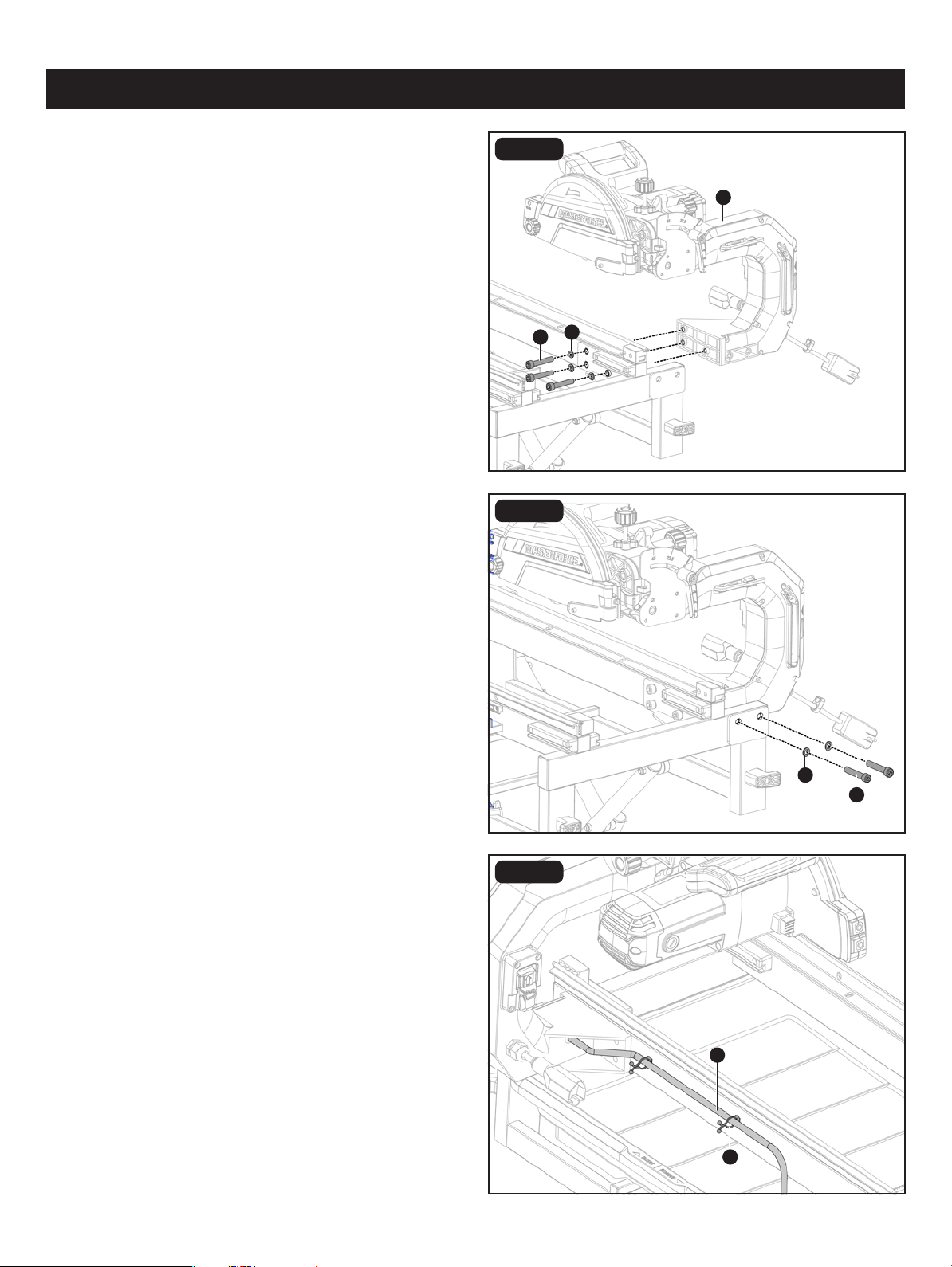
ASSEMBLY
FIG. 4C
FIG. 4A
INSTALLING MOTOR HEAD TO FRAME
AND STAND ASSEMBLY (Fig. 4A-4C)
• Align holes in motor head assembly (A) with holes on side
of metal frame. Insert hex cap screws M10 x 52 (D) through
at washers 10 (C) and into motor head assembly. Secure
with 8mm hex key (supplied).
• Insert hex cap screws M10 x 52 (D) through at washers
10 (C) and into back side of frame and into holes of motor
head assembly. Secure with 8mm hex key (supplied).
• Place clear tube (KK) from motor head assembly into two
hose clamps (LL) on frame. Squeeze clamp ends together
to secure tube.
FIG. 4B
D
A
C
C
KK
LL
D
Page 16
FIG. 5
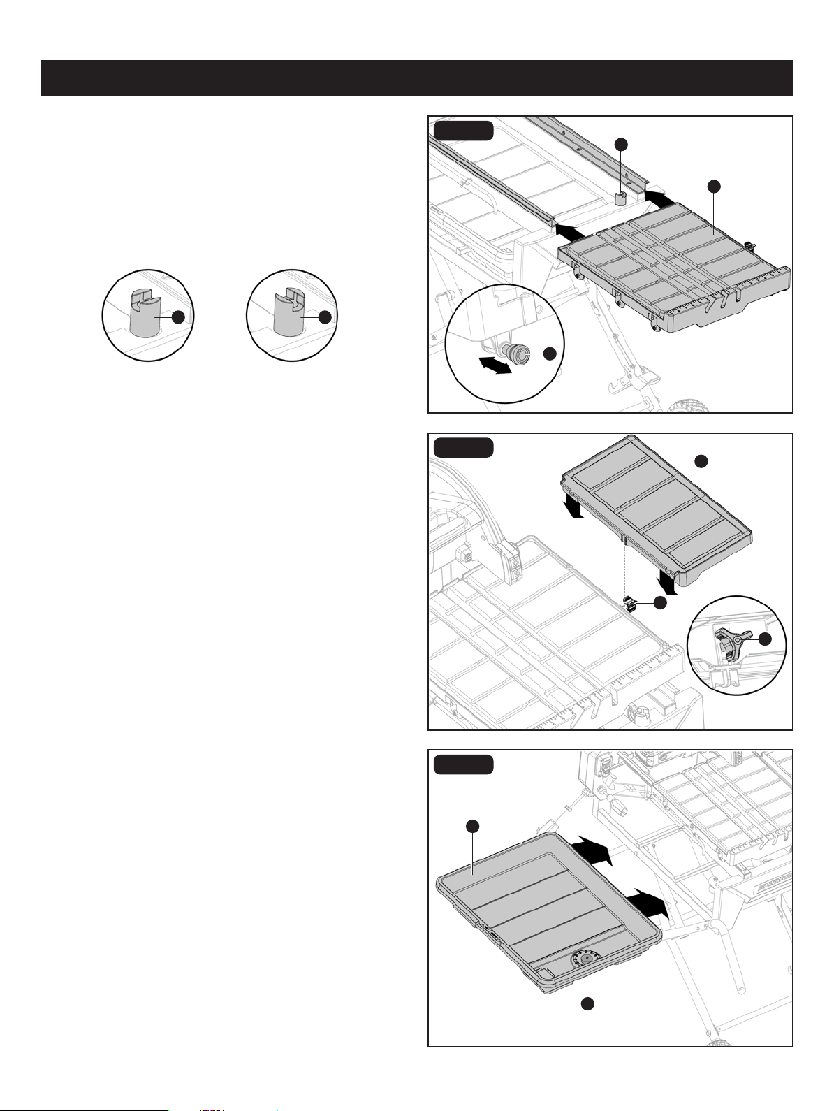
INSTALLING THE TABLE (Fig. 5)
• From right side of table (E), pull the table lock lever (MM)
out, rotate table stop (NN) to unlock position. Grasp table
(E) rmly and set rollers on rails of frame. Holding table (E)
parallel with frame, push table toward back of tile saw.
• Push table (E) along rails until nal rollers engage rails.
Rotate table stop (NN) to lock position.
ASSEMBLY
FIG. 6
FIG. 7A
INSTALLING THE EXTENSION TABLE
(Fig. 6)
• Hang the extension table (F) on the right side of the table
with the middle slot inserted into the bolt of the extension
table lock knob (OO). Tighten the lock knob underneath
the extension table clockwise to secure in place.
INSTALLING THE WATER TRAY AND
TRAY EXTENSION (Fig. 7A-7E)
• From the left side of the tile saw, place the water tray (L)
(drain plug (PP) end to the right) on the lip at the bottom
of the water tray frame.
• Slide the water tray in under the table until it hits the stops
on the other side of the frame.
NN
A
F
L
PP
To
lock
Locked Unlocked
To
unlock
NN NN
MM
OO
OO
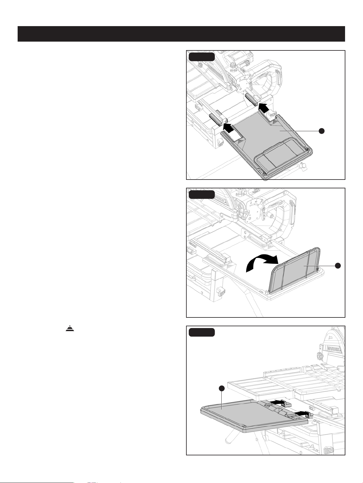
FIG. 7C
FIG. 7D
ASSEMBLY
Page 17
FIG. 7B
• Standing at back of tile saw, insert rear extension tray (J)
into grooves in water tray holder on the water tray frame.
• Rotate ap (QQ) on rear extension tray to vertical position.
• Align engraved on side extension tray A (H) with rail
hooks on frame and stand assembly. Slightly angle side
extension tray A. Lower down to hang on hooks.
C
J
H
QQ
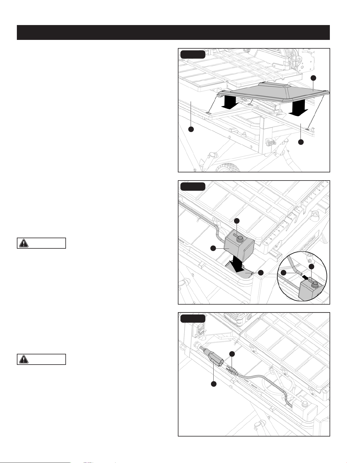
FIG. 7E
• Place the hooks on side extension tray B (I) into the
corresponding holes on side extension tray A (H). Lower
side extension tray B to a horizontal position and place
the hook on other end of the side extension tray B (I) into
the hole on the rear extension tray (J).
FIG. 8A
INSTALLING THE WATER PUMP
(Fig. 8A-8B)
• Place the water pump (K) into the pump basin (RR). Press
down rmly on the water pump to attach its suction feet
to the bottom of the water tray. Connect the clear tube
(KK) to the barbed hose connector tting (SS).
Page 18
ASSEMBLY
CAUTION: Make sure the tube doesn’t contact
the bottom of the table and interfere with table movement.
Adjust the position of the tube or water pump if necessary.
CAUTION: The receptacle is only connected with
the water pump.
K
KK
J
I
SS
UU
TT
SS
H
FIG. 8B
• Make sure your hands are dry and the tile saw is
unplugged. Push back rubber boot on the pump outlet
(TT) and plug pump power cord (UU) into outlet. Pull rubber
boot back into place to cover the connection and help
keep water off plug.
RR
WARNING: DO NOT use tile saw blades rated less
than the no load speed of this tile saw. Failure to heed this
warning could result in personal injury. DO NOT use a tile
saw blade with cracks, gaps, or teeth.
WARNING: A 10 in. tile saw blade is the maximum
blade capacity of the tile saw. NEVER use a tile saw blade
that is too thick to allow blade washer to engage with the
ats on the spindle. Larger blades will come in contact with
the splash guard, while thicker blades will prevent the blade
bolt from securing the blade on the spindle. Either of these
situations could result in serious accidents and can cause
serious personal injury.
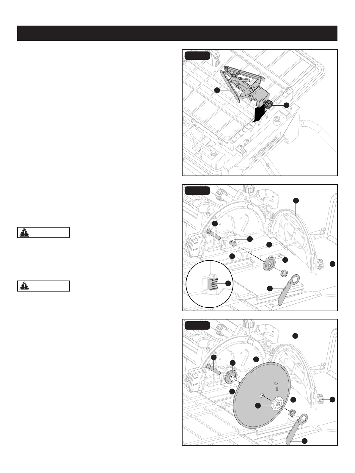
FIG. 9
FIG. 10A
INSTALLING THE MITER GUIDE (Fig. 9)
The miter guide can be used from both the left and right
side of the tile saw blade.
• Place slot on underside of the miter guide (G) on table
fence. Lock the miter guide (G) securely to table by turning
lock knob (VV) clockwise.
THE SAW BLADE (Fig. 10A-10B)
INSTALLING THE SAW BLADE
For maximum performance and safety, it is recommended
that you use the 10 in. tile saw blade provided with your tile saw.
Additional tile saw blades are available at your local retailer.
• Unplug the tile saw.
• Turn the blade guard knob (WW) counterclockwise. Open
the blade guard (XX) to expose the spindle.
• Press and hold the spindle lock (YY) in. Loosen the spindle
nut (ZZ) counterclockwise and remove the nut (ZZ), outer
ange (aa).
• Leave the inner ange (bb) on the spindle (cc), making sure
the cupped side of the ange is facing the tile saw housing.
• Wipe a drop of oil onto the inner ange where it will contact
the blade.
• Slide the tile saw blade (M) onto spindle (cc). Make sure
that the tile saw blade’s rotation arrow points in the same
direction as the rotation arrow on the blade guard.
Page 19
ASSEMBLY
P
G
YY
P
bb
VV
cc
cc
aa
M
XX
XX
dd
dd
ZZ
bb
ZZ
FIG. 10B
WW
WW
aa
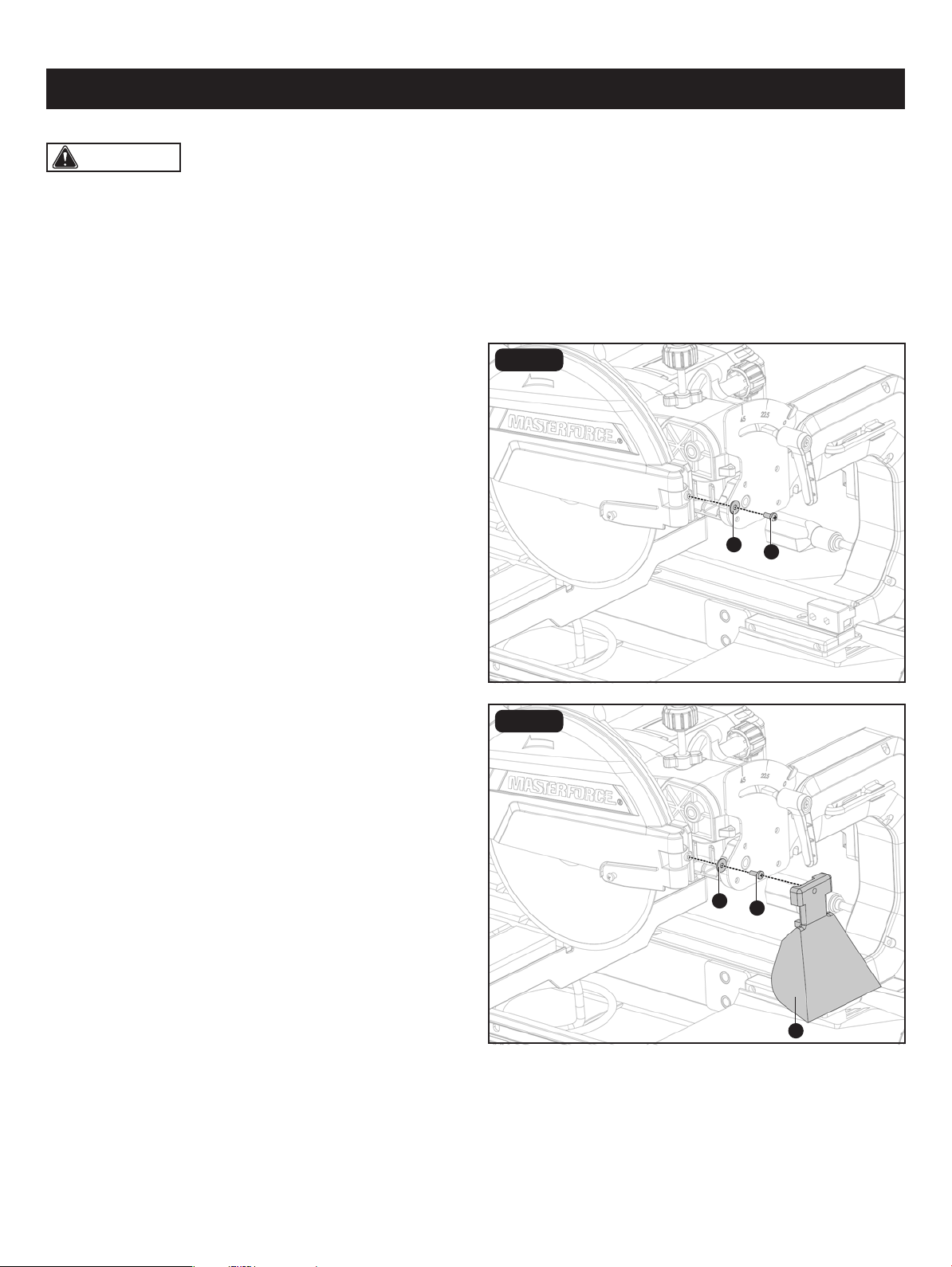
FIG. 11A
INSTALLING THE SPLASH GUARDS
(Fig. 11A-11C)
• Remove M5 x 12mm cross screw (ee) and big at washer
5 (ff) from the motor head assembly.
• Attach the rear splash guard (O) to the back of the blade
guard with the big at washer 5 (ff) and M5 x 12 cross
screw (ee).
• Place outer ange (aa) onto the spindle (cc). The ats on the outer ange align with the ats on the spindle. Install with
the cupped side of the outer ange facing the tile saw blade.
• Place spindle nut (ZZ) on spindle (cc). Press and hold the spindle lock (YY) in. Wrench (J) tighten spindle nut securely.
Release the spindle lock.
• Close the blade guard (XX), and use the guard knob (WW) to secure it.
Page 20
ASSEMBLY
CAUTION: The tile saw is equipped with two water nozzles (dd) to wet the tile saw blade during operation. Make
sure holes in nozzles face the tile saw blade and that tile saw blade is positioned between the two nozzles.
ee
ff
ee
O
ff
FIG. 11B
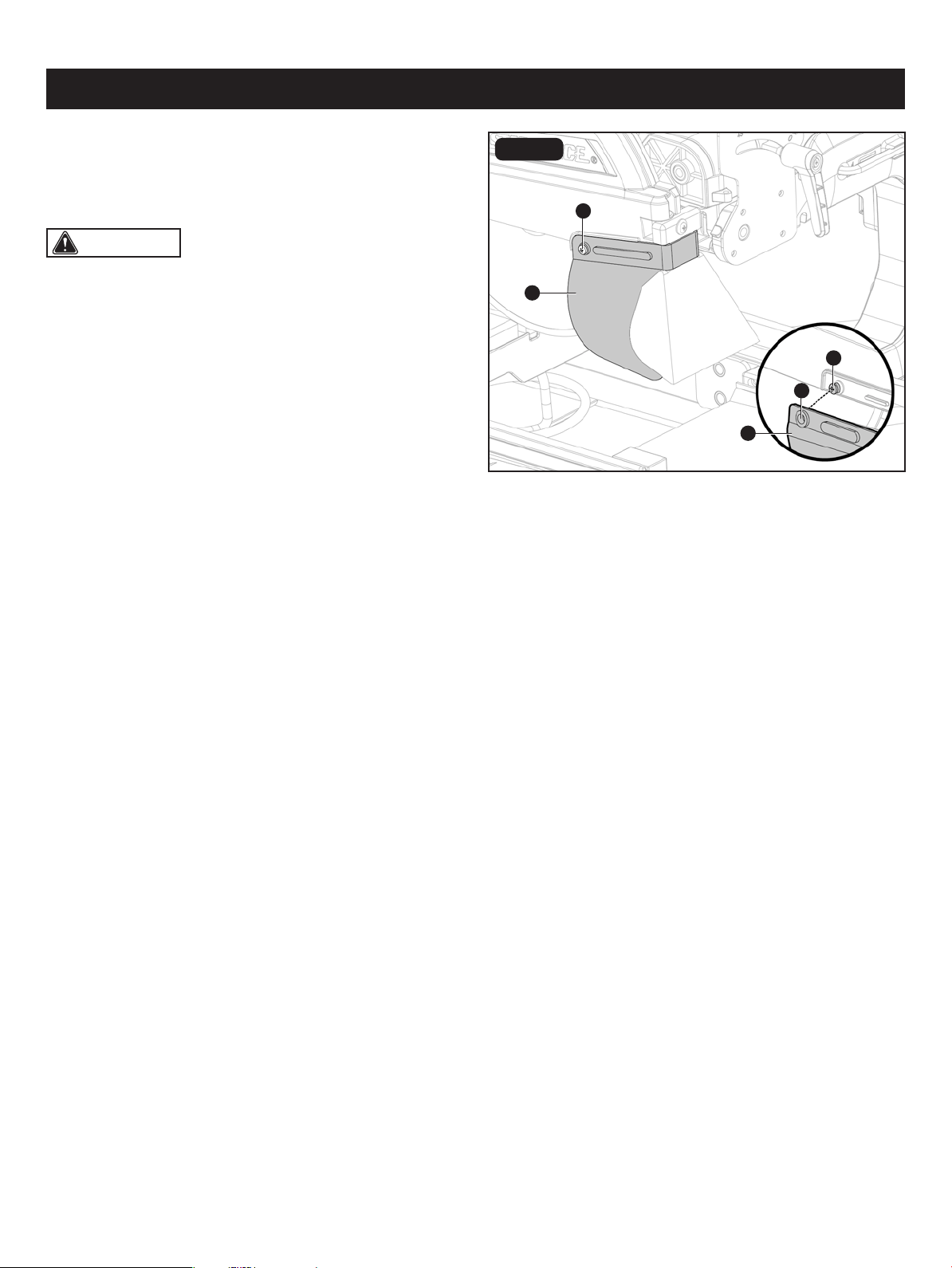
• Align the hole (gg) on each end of the side splash guard
(N) to the screw (hh) on each side of the blade guard and
press the holes (gg) on the splash guard through the
screws (hh).
Page 21
ASSEMBLY
CAUTION: It is not necessary to loosen or remove
the screws (F) on the blade guard to install the side splash
guard.
N
N
FIG. 11C
gg
hh
hh
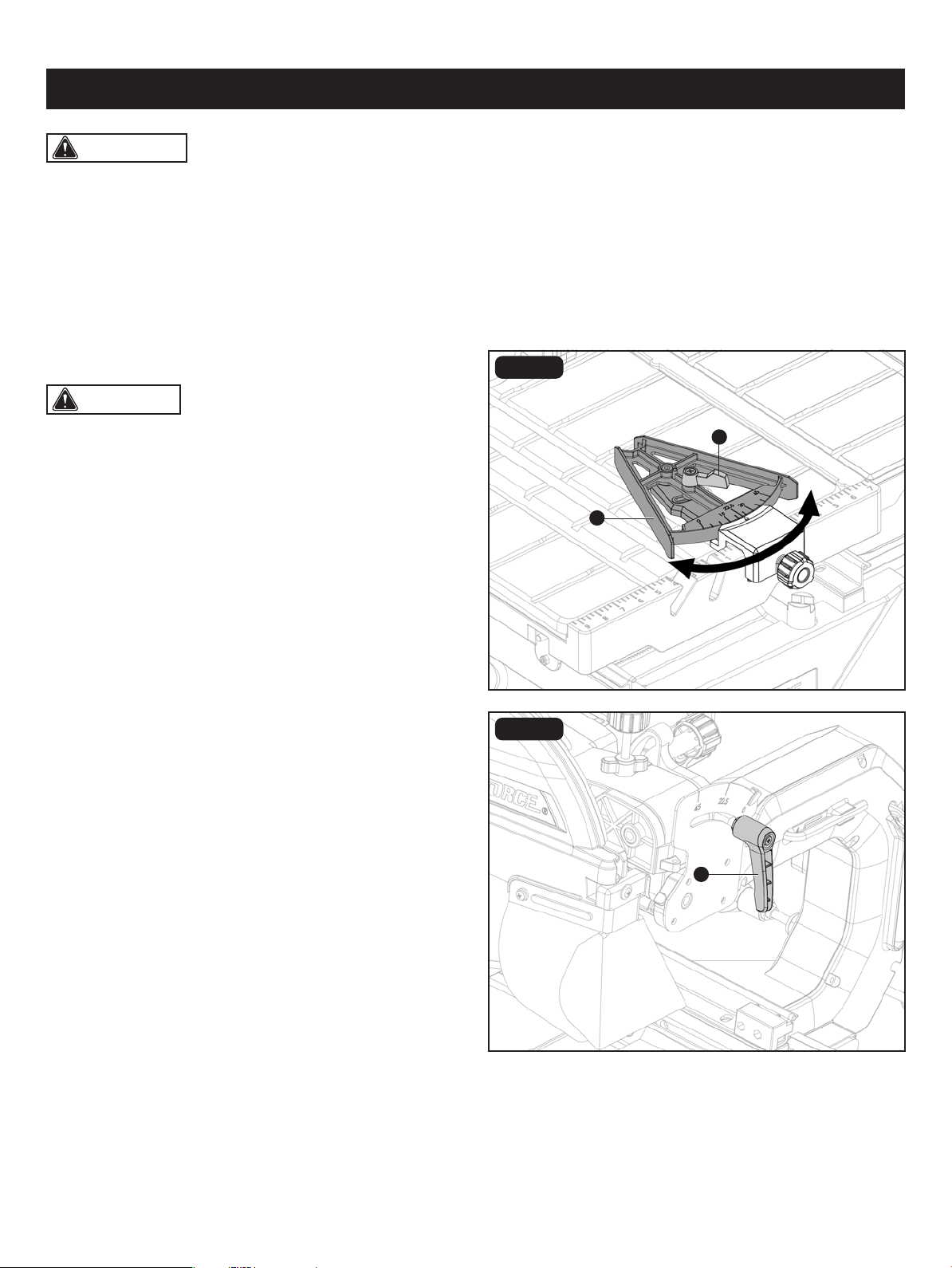
FIG. 12
MITER ADJUSTMENT (Fig. 12)
WARNING: DO NOT allow familiarity with the tile saw to make you careless. Always wear safety protection. Failure
to do so could result in objects being thrown into your eyes, resulting in possible serious injury. DO NOT use any attachments
or accessories not recommended by the manufacturer of this tile saw. The use of attachments or accessories that aren't
recommended can result in serious injury.
APPLICATIONS
You may use this tile saw for the purpose listed below:
• Straight line cutting operations such as cross cutting, mitering, ripping, and beveling.
To adjust angles:
• Loosen the miter lock lever (ii).
• Set to the desired angle by moving the gauge (jj) left or
right.
• Tighten the miter lock lever (ii) securely before turning on
the tile saw.
OPERATION
Page 22
CAUTION: The miter gauge can be used from either
the left or the right side of the tile saw blade.
jj
ii
FIG. 13
BEVEL ADJUSTMENT (Fig. 13)
• Slide the table clear of the tile saw blade to prevent tile
saw blade damage.
• Loosen the bevel lock lever (kk).
• Adjust the motor head to the desired angle: 0º, 22.5º or
45º. Do not set bevel to any other setting. The slots in the
table are designed only for these cuts.
• Tighten the bevel lock lever (kk).
kk
Page 23
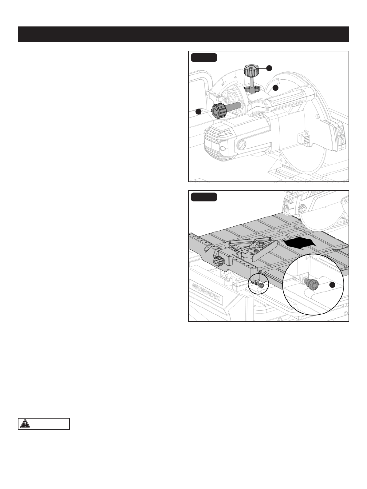
FIG. 14
DEPTH ADJUSTMENT (Fig. 14)
• Depth knob: The depth knob (ll) can be used to lock the
motor head at a particular cutting depth; tighten it to lock
the motor head in place, loosen it to allow adjustment.
• Depth stop: This controls the maximum cut depth. If the
blade cuts too deeply or too shallowly; loosen the depth
stop lock (mm), adjust the depth stop (nn), and tighten the
depth stop lock (mm) again.
LOCKING AND UNLOCKING THE TABLE
(Fig. 15)
• Align the table lock lever (MM) and the hole on rail.
• Push the table lock lever (MM) into the hole to lock.
• From the right side of the table, pull the table lock lever
(MM) out.
WORKPIECE AND WORK AREA SET UP
• Designate a work area that is clean and well-lit. The work area must not allow access by children or pets to prevent
distraction and injury.
• Route the power cord along a safe route to reach the work area without creating a tripping hazard or exposing the power
cord to possible damage. The power cord must reach the work area with enough extra length to allow free movement
while working.
• There must not be objects, such as utility lines, nearby that will present a hazard while working.
• Keep workpieces pressed rmly against the table and fence while cutting.
• Mark cut lines using waterproof marker or crayon.
OPERATION
CAUTION: This tile saw is intended for use on man-made masonry and tile products only.
ll
FIG. 15
mm
nn
MM
LASER RADIATION
DO NOT STARE INTO BEAM
Max. output: < 1 mW,
Wavelength: 650nm
CLASS II LASER PRODUCT
This product complies with
21 CFR 1040.10 AND 1040.11
AVOID EXPOSURE
Laser radiation emitted
from this aperture.
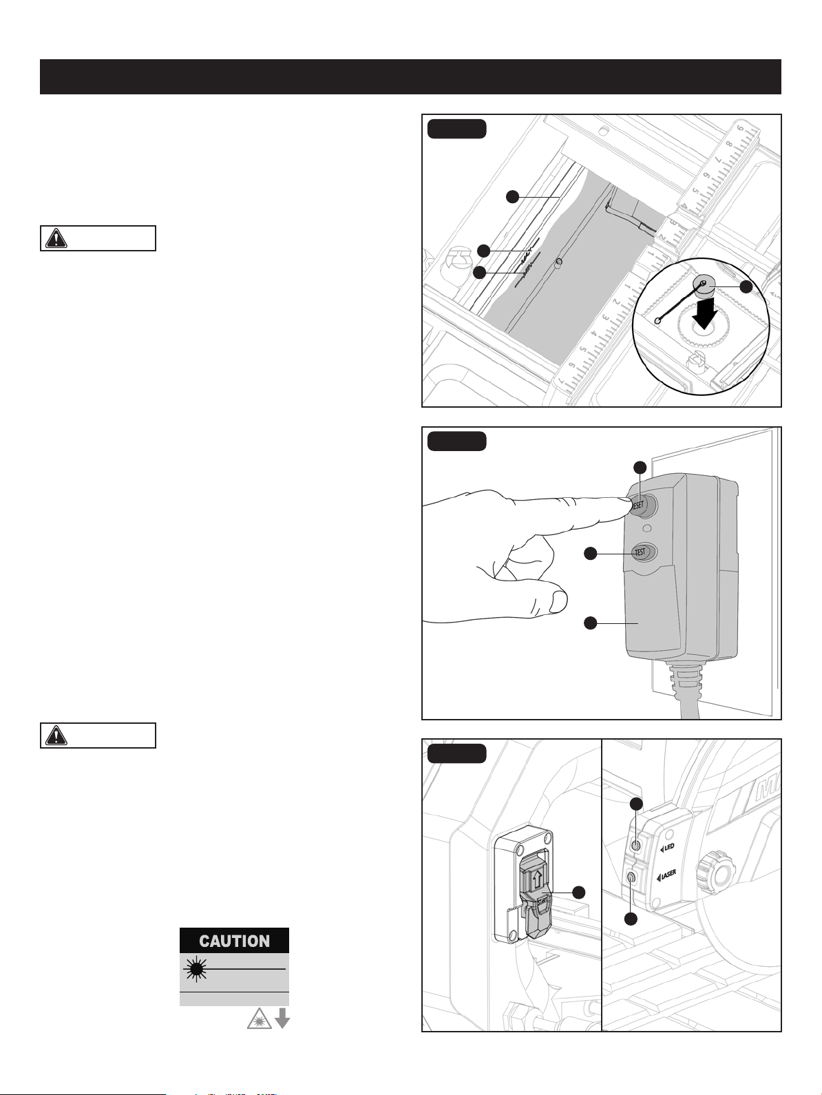
GENERAL OPERATING INSTRUCTIONS
(Fig. 17A-17C)
• Adjust the miter, bevel, and depth settings as needed.
Refer to previous page 22-23. Lock all settings in place.
• Place the workpiece on the table and rmly against the
miter gauge and fence.
• Make sure the workpiece is clear of the tile saw blade and
that the switch is in the off-position, then plug in the tile saw.
• The tile saw is equipped with an On/Off switch that has a
built-in locking feature. To turn the tile saw ON:
• Press the reset button (qq) on the Ground Fault Circuit
Interrupter (GFCI) (uu) . Indicator should turn on.
• Press the test button (vv). Indicator should turn off.
• Press the reset button (qq) again, then lift the ON/OFF
switch (ww) up.
• To turn the tile saw OFF, press the ON/OFF switch (ww)
down.
• To lock the ON/OFF switch, place it in the OFF position
and insert a padlock (not included) through the hole in the
switch.
• To turn on the laser guide, press the laser switch (xx). Press
again to turn off.
To turn on the LED Light, press the LED switch (yy). Press
again to turn off.
Page 24
CAUTION: Water level must be kept above minimum
ll line (oo) and below maximum ll line (pp) at all times during
operation or damage to the pump and/or tile saw blade will
occur.
CAUTION: Do not use if above test fails.
FIG. 17
FIG. 17A
FIG. 17B
FILLING THE WATER TRAY (FIG. 16)
• Place the drain plug (PP) into the hole on the bottom of
the water tray (L).
• Fill the water tray (L) with clean water up to the maximum
ll line before every use.
OPERATION
L
pp
oo
vv
uu
qq
xx
yy
PP
ww
Page 25
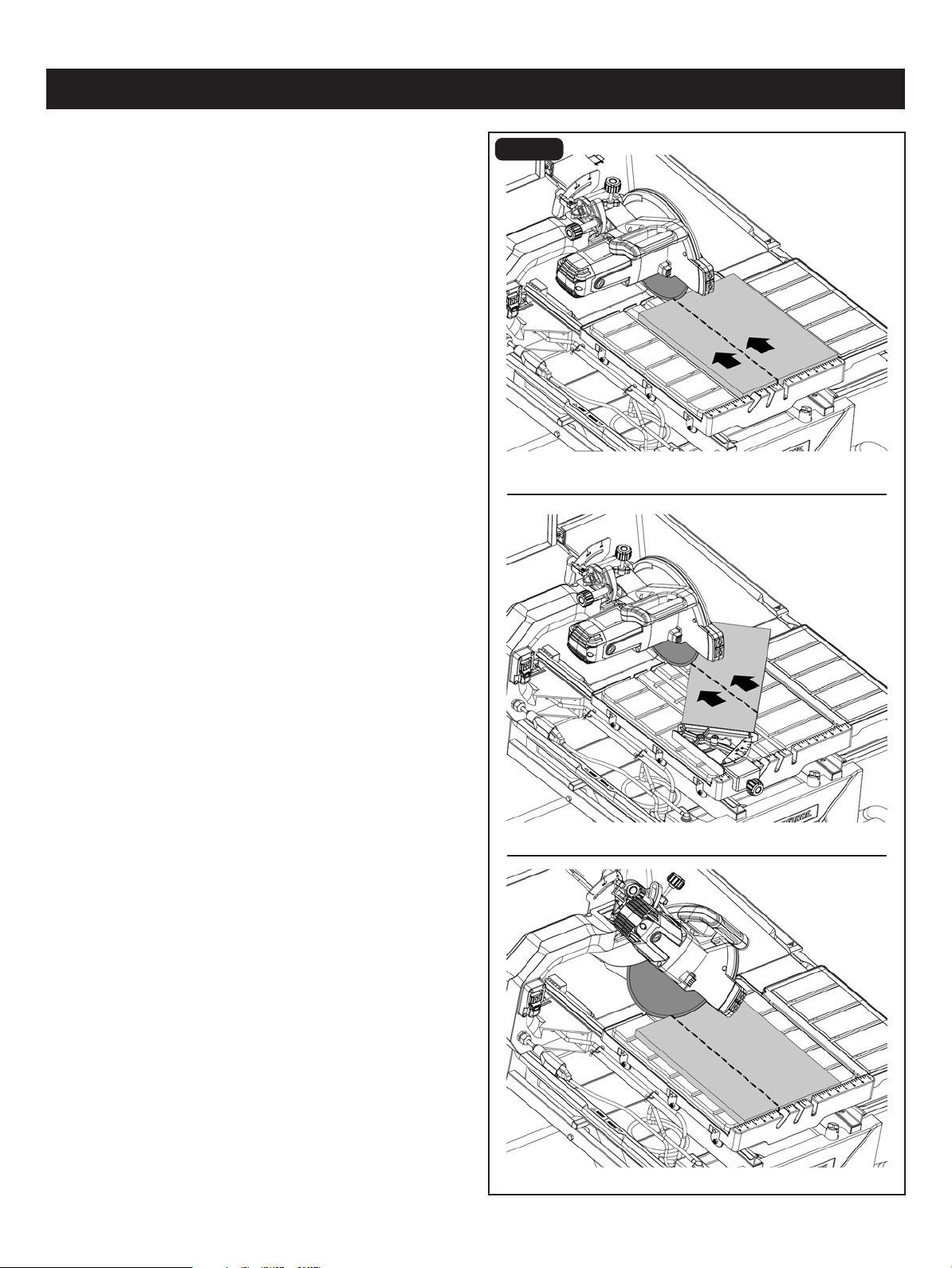
OPERATION
FIG. 17C
• With the tile saw running, make sure the pump is supplying
enough water to the tile saw blade.
• Let the tile saw blade build up to full speed before cutting.
• Use two hands and hold workpiece securely against table
and fence at all times. Feed the material into the tile saw
blade.
• When the cut is made, turn the tile saw off. Wait for the tile
saw blade to come to a complete stop before removing
any part of the workpiece.
• To prevent accidents, turn off the tile saw and unplug the
tile saw from its electrical outlet after use. Clean, then
store the tile saw indoors out of children’s reach.
STRAIGHT CUT
MITER CUT
BEVEL CUT
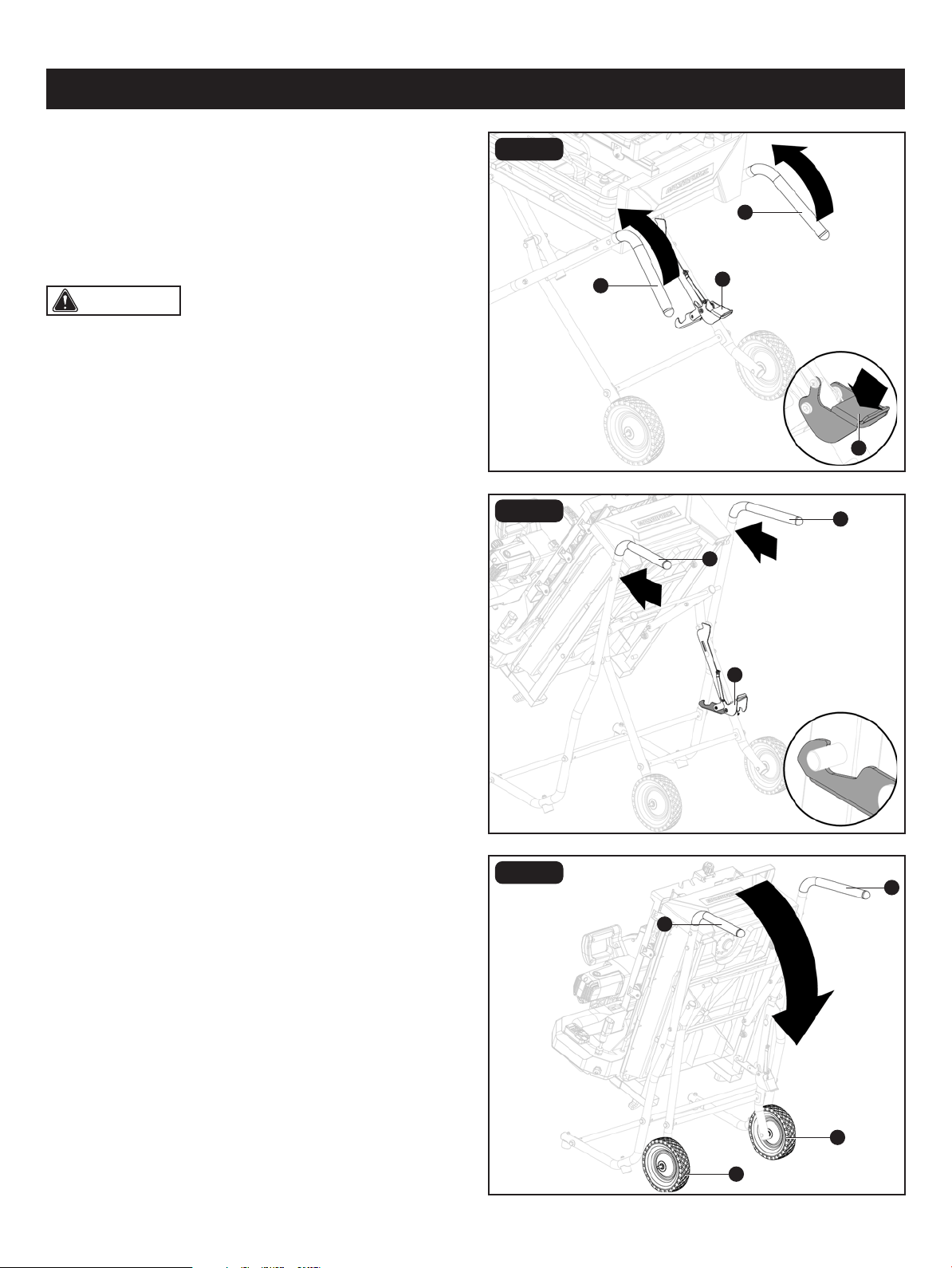
Page 26
CAUTION: When storing, place the rear extension
tray at the bottom, side extension tray B on the middle and
rear extension tray A on the top.
FIG. 18A
FIG. 18B
FIG. 18C
OPERATION
CLOSING OR OPENING STAND
(FIG. 18A-18E)
• Unplug the tile saw and water pump.
• Remove water rear and side extension trays and store
them inside the water tray.
Remove any work pieces from the tile saw.
CLOSING STAND (FIG. 18A-18B)
• At the same time, step on release lever (JJ), grasp handles
(EE) and lift them up and away from the body.
• Push the tile saw until the release lever (JJ) clicks and locks
into place.
MOVING STAND (FIG. 18C)
• Holding the handles (EE) rmly, pull the handles toward you
until the stand and tile saw are balanced on the wheels (FF).
• Push the tile saw to the desired location then either open
the stand for tile saw operation or store the tile saw in a
dry environment.
• Place the table in front of the frame and lock the table in
place.
IMPORTANT: Ensure that the table is locked in place
before closing the stand.
• Lower the wheel and secure by locking the tile saw head
in place using the lock knob.
JJ
JJ
JJ
EE
EE
EE
EE
EE
EE
FF
FF
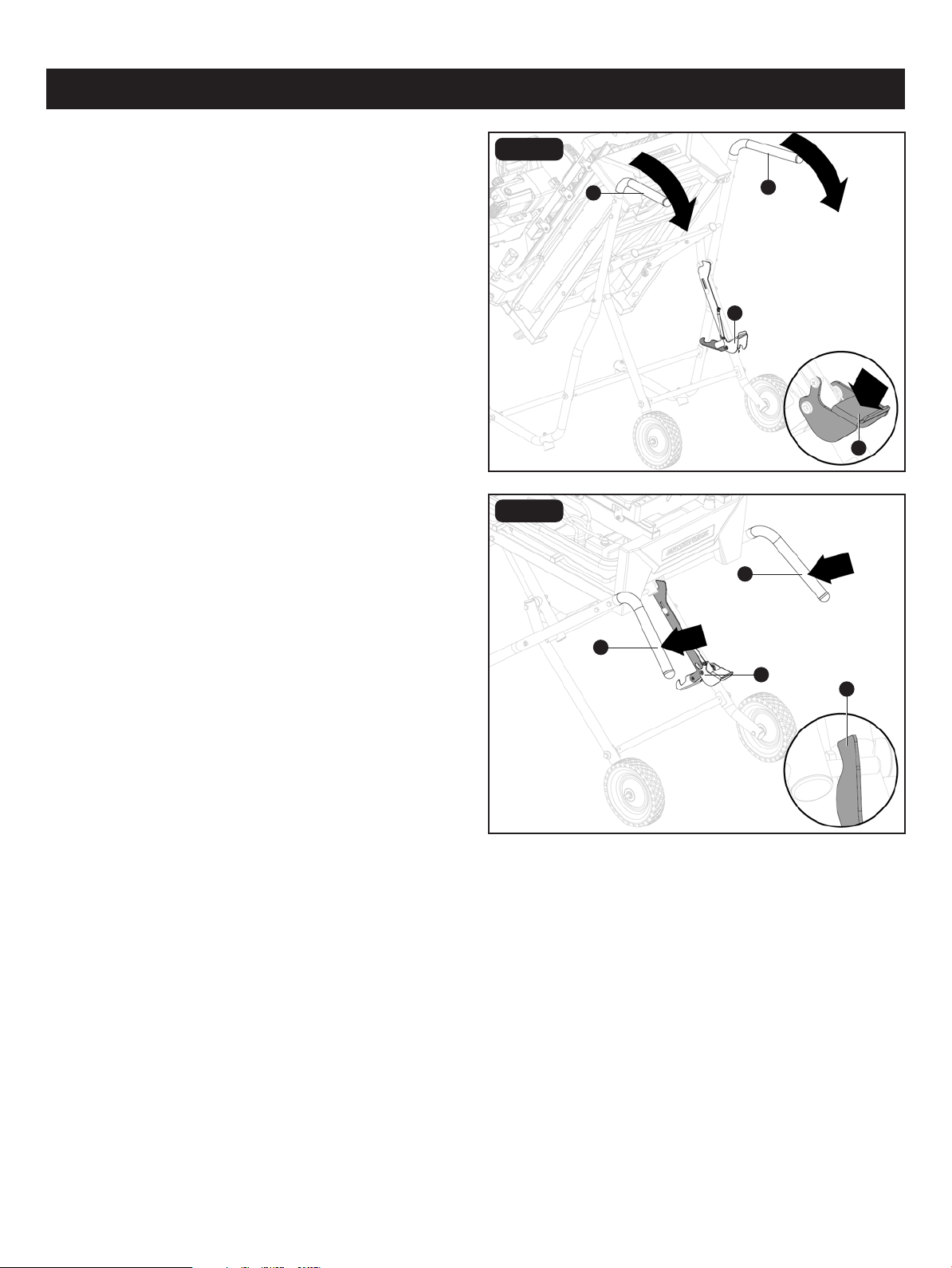
Page 27
OPERATION
• With your hands on the handles (EE), push the stand toward
the ground until the tile saw is in an open position with
the release lever (JJ) locking into place.
OPENING STAND (FIG. 18D-18E)
• Step on the release lever (JJ) and pull the handles (EE)
toward you at the same time.
• Once the stand is released from the release lever, ease
the stand toward the oor by pushing the handles toward
the oor.
JJ
FIG. 18D
JJ
FIG. 18E
JJ
JJ
EE
EE
EE
EE
WARNING: When servicing, use only identical Masterforce replacement parts. Use of any other parts may create a
hazard or cause product damage. ALWAYS wear eye protection with side shields marked to comply with ANSI Z87.I during
product operation. If operation is dusty, also wear a dust mask. DO NOT at any time let brake uids, gasoline, petroleum-
based products, penetrating oils, etc., come in contact with plastic parts. Chemicals can damage, weaken or destroy plastic
which may result in serious personal injury.
Page 28
Avoid using solvents when cleaning plastic parts. Most plastics are susceptible to damage from various types of commercial
solvents and may be damaged by their use. Use clean cloths to remove dirt, dust, oil, grease, etc.
LUBRICATION
All of the bearings in this tile saw are lubricated with a sufcient amount of high grade lubricant for the life of the unit under
normal operating conditions. After extended use, clean the rails so the table will slide smoothly.
CLEANING THE TILE SAW
• Unplug the tile saw and water pump.
• Empty the dirty water from the water tray and replace with clean water.
• Rinse off the sliding table.
• Unlock table stop (turning until the slot is vertical).
• Grasp the table rmly before pulling the table to the front and off the tile saw.
• Once the table has been removed, rinse the rails and water tray frame.
• Empty dirty water from the water tray and dry off the tile saw.
CLEANING THE RAILS
• During use, the rails will become dirty, preventing the table rollers from sliding smoothly. It is important to clean the rails
often.
CLEANING THE SUBMERSIBLE PUMP
• Unplug pump before handing or cleaning the pump.
• Remove the front cover.
• Using a small brush and/or water, clean any debris or trash that is trapped on the side of the pump.
If the pump will not run, try the following solutions:
• Ensure that the intake screen is free of obstruction.
• Make sure that the water hose isn’t clogged or knotted.
• Be sure the unit is plugged into a functioning power outlet.
• Be sure there is adequate water in the water tank
MAINTENANCE
CAUTION: To maintain efciency and extend the life of the pump, check intake screen before use to make sure
it is clean.
CAUTION: To prevent accidental starting, do not handle the pump while it is connected to a power source.
Page 29
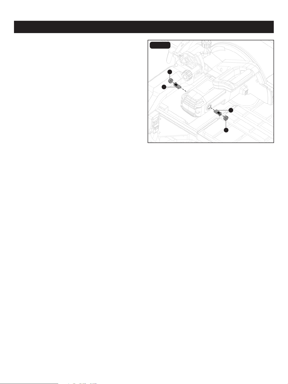
BRUSH REPLACEMENT (FIG. 19)
MAINTENANCE
Aa
Aa
FIG. 19
The tile saw has externally accessible brush assemblies that
should be periodically checked for wear.
Proceed as follows when replacement is required:
• Unplug the tile saw.
• Remove brush cap (zz) with a at head screwdriver (not
included). Brush assembly (Aa) is spring loaded and will
pop out when you remove brush cap (zz).
• Remove brush assembly (Aa).
• Check for wear. Replace both brushes when either has
less than 1/4 in. length of carbon remaining. DO NOT
replace one side without replacing the order.
• Reassemble using new brush assemblies (not included).
Make sure curvature of brush matches curvature of motor
and that brush moves freely in brush tube.
• Make sure brush cap is oriented correctly (straight) and
replace.
• Tighten brush cap securely. Do not overtighten.
zz
zz

Page 30
TROUBLESHOOTING
Motor is too hot. • Turn off machine and let it cool down to
room temperature.
• Check and clean ventilation.
• The machine is overheated.
• Ventilation is obstructed.
Motor stops turning. • Verify that all electrical connections are
secure.
• Check that power source voltage is 120 V.
• Verify that switch is in the "ON" position.
• Plugs have not been fully connected.
• Incorrect voltage.
• Switch is "OFF".
PROBLEM PROBLEM CAUSE CORRECTIVE ACTION
Pump cannot inject water. • Verify that there is sufcient water in
water tray.
• Make sure water hose is rmly attached.
• Check that pump electrical cord is
securely attached to receptacle.
• Remove foam lter, rinse and replace in
pump.
• The water in tray is not deep enough.
• The water hose is loose or has come off.
• The pump electrical cord is not rmly
connected to receptacle.
• The foam lter in inlet pump is too dirty.
Laser line projection is hard
to see.
• Turn down the environment light.
• Clean the dust or water on the cover at
the aperture.
• Light in work area is too bright.
• Dust or water is on the cover of aperture.
Laser does not work. • Check that the laser switch is in the "on"
position.
• Laser switch is in the "off" position.
The movement of table is not
smooth.
• Remove the mud or tile debris on rails.• There is debris buildup on rails.
Page 31
REPLACEMENT PARTS LIST
A 70939120001
70939120002
70939120003
70939120010
70939120012
Rear Splash Guard
Side Splash Guard
Table Lock Lever
PART DESCRIPTION PART#
J
B
LC
70939120004Roller WheelD
70939120009Extension Table Lock KnobI
70939120008Motor Lock KnobH
70939120007Bevel Lock LeverG
70939120006Depth Stop Knob AssemblyF
70939120005Miter GaugeE
70939120011K
Table Stop
Arbor Wrench
Hex Key
70939120013
M Hardware for Stand
70939120014
N Hardware for Roller Wheel
70939120015
O Hardware for Handle
70939120016
P Hardware for Motor Head
70939120017
Q
Hardware for Rear
Splash Guard
70939120018
R Blade Lock Assembly
PART DESCRIPTION PART#
For questions / comments, technical assistance or repair parts - Please call toll free at: 1-877-684-8912 (Monday - Friday
8am - 6pm EST.)
FIG. 20
A
B
C
D
E
F
G
H
I
J
K
L
M
N
O
P
Q
R
Page 32
Distributed by: Menard, Inc., Eau Claire, WI 54703
SAVE YOUR RECEIPTS
THIS WARRANTY IS VOID WITHOUT THEM
10" Sliding Tile Saw
WARRANTY
90-DAY MONEY BACK GUARANTEE:
This MASTERFORCE
®
brand power tool carries our 90-DAY Money Back Guarantee.
If you are not completely satisfied with your MASTERFORCE
®
brand power tool
for any reason within ninety (90) days from the date of purchase, return the tool with
your original receipt to any MENARDS
®
retail store, and we will provide you a refund –
no questions asked.
3-YEAR LIMITED WARRANTY:
This MASTERFORCE
®
brand power tool carries our famous No Hassle 3-Year Limited
Warranty to the original purchaser. If, during normal use, this MASTERFORCE
®
power
tool breaks or fails due to a defect in material or workmanship within three (3) years
from the date of original purchase, simply bring this tool with the original sales receipt
back to your nearest MENARDS
®
retail store. At its discretion, MASTERFORCE
®
agrees to have the tool or any defective part(s) repaired or replaced with the same or
similar MASTERFORCE
®
product or part free of charge, within the stated warranty
period, when returned by the original purchaser with original sales receipt. Not
withstanding the foregoing, this limited warranty does not cover any damage that
has resulted from abuse or misuse of the Merchandise. This warranty: (1) excludes
expendable parts including but not limited to blades, brushes, belts, bits, light bulbs,
and/or batteries; (2) shall be void if
this tool is used for commercial and/or rental
purposes; and (3) does not cover any losses, injuries to persons/property or costs. This
warranty does give you specific legal rights and you may have other rights, which vary
from state to state. Be careful, tools are dangerous if improperly used or maintained.
Seller’s employees are not qualified to advise you on the use of this Merchandise.
Any oral representation(s) made will not be binding on seller or its employees. The
rights under this limited warranty are to the original purchaser of the Merchandise
and may not
be transferred to any subsequent owner. This limited warranty is in lieu
of all warranties, expressed or implied including warranties or merchantability and
fitness for a particular purpose. Seller shall not be liable for any special, incidental, or
consequential damages. The sole exclusive remedy against the seller will be for the
replacement of any defects as provided herein, as long as the seller is willing or able
to replace this product or is willing to refund the purchase price as provided above.
For insurance purposes, seller is not allowed to demonstrate an
y of these power tools
for you.
For questions / comments, technical assistance or repair parts – Please Call Toll
Free at: 1-877-684-8912. (M-F 8am – 6pm)