Loading ...
Loading ...
Loading ...
EN-6 452235.66.05 · FD 9310 www.dimplex.de
English
SI 6TU - SI 18TU
Minimum heating water flow rate
The minimum heating water flow rate through the heat pump
must be assured in all operating states of the heating sys-
tem. This can be accomplished, for example, by installing either
a dual differential pressureless manifold or an overflow valve.
The procedure for adjusting an overflow valve is described in the
Chapter Start-Up.
NOTE
The use of an overflow valve is only recommended for panel heating and
a max. heating water flow of 1.3 m³/h. System faults may result if this is
not observed.
The antifreeze function of the heat pump manager is active
whenever the heat pump manager and the heat circulating
pumps are ready for operation. If the heat pump is taken out of
service or in the event of a power failure, the system has to be
drained. The heating circuit should be operated with a suitable
antifreeze if heat pump systems are implemented in buildings
where a power failure can not be detected (holiday home).
7.3 Heat Source Connection
The following procedure must be observed when connecting the
heat source:
Connect the brine pipe to the heat pump flow and return. The hy-
draulic integration diagram must be adhered to.
ATTENTION!
The supplied dirt trap must be inserted in the heat source inlet of the heat
pump to protect the evaporator against the ingress of impurities.
The brine liquid must be produced prior to charging the system.
The liquid must have an antifreeze concentration of at least 25 %
to ensure frost protection down to -14 °C.
Only monoethylene glycol or propylene glycol-based antifreeze
may be used.
The heat source system must be de-aerated and checked for
leaks.
ATTENTION!
The brine solution must contain at least a 25 % concentration of a
monoethylene glycol or propylene glycol-based antifreeze, which must
be mixed before filling.
NOTE
If necessary, the operating range can be extended to a brine inlet
temperature of -10 °C. In this case, the minimum brine concentration
must be adjusted to 30 %. (Freezing temperature -17 °C)
ATTENTION!
The maximum test pressure in the heating circuit and the brine circuit is
6.0 bar (ü). This value must not be exceeded.
NOTE
A suitable de-aerator (micro bubble air separator) must be installed in the
heat source circuit by the customer.
7.4 Temperature sensor
The following temperature sensors are already installed or must
be installed additionally:
External temperature sensor (R1) supplied (NTC-2)
Return temperature heating circuit (R2) installed (NTC-10)
Return temperature primary circuit (R24) installed (NTC-10)
Flow temperature heating circuit (R9) installed (NTC-10)
Flow temperature primary circuit (R6) installed) (NTC-10)
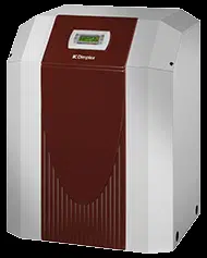
7.4.1 Sensor characteristic curves
The temperature sensors to be connected to the heat pump ma-
nager must correspond to the sensor characteristic curve illustra-
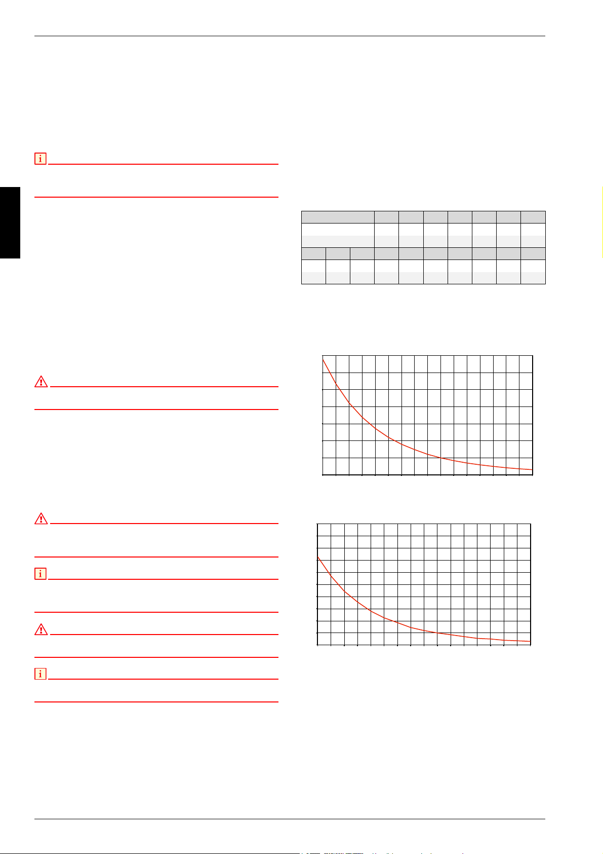
ted in Fig.7.1 on pag. 6. The only exception is the external tem-
perature sensor included in the scope of supply of the heat pump
(see Fig.7.2 on pag. 6)
Fig. 7.1:Sensor characteristic curve NTC 10
Fig. 7.2:Sensor characteristic curve, standardised NTC-2 ac-
cording to DIN 44574 External temperature sensor
Temperature in °C -20 -15 -10 -5 0 5 10
NTC-2 in k 14.6 11.4 8.9 7.1 5.6 4.5 3.7
NTC-10 in k 67.7 53.4 42.3 33.9 27.3 22.1 18.0
15 20 25 30 35 40 45 50 55 60
2.9 2.4 2.0 1.7 1.4 1.1 1.0 0.8 0.7 0.6
14.9 12.1 10.0 8.4 7.0 5.9 5.0 4.2 3.6 3.1
([WHUQDOWHPSHUDWXUHLQ>&@
5HVLVWDQFHYDOXHLQ>N2KP@
([WHUQDOWHPSHUDWXUHLQ>&@
5HVLVWDQFHYDOXHLQ>N2KP@
Loading ...
Loading ...
Loading ...