Sole/Wasser-
Wärmepumpe für
Innenaufstellung
SI 6TU
SI 8TU
SI 11TU
SI 14TU
SI 18 TU
Brine-to-Water
Heat Pump for
Indoor Installation
Pompe à chaleur
eau glycolée-eau
pour installation
intérieure
Montage- und
Gebrauchsanweisung
DeutschEnglishFrançais
Instructions d’installation
et d’utilisation
Installation and
Operating Instructions
Bestell-Nr. / Order no. / N
o
de commande : 452235.66.05 FD 9310


www.dimplex.de 452235.66.05 · FD 9310 DE-1
Deutsch
SI 6TU - SI 18TU
Inhaltsverzeichnis
1 Bitte sofort lesen ........................................................................................................................ DE-2
1.1 Wichtige Hinweise ............................................................................................................................... DE-2
1.2 Bestimmungsgemäßer Gebrauch........................................................................................................ DE-2
1.3 Gesetzliche Vorschriften und Richtlinien ............................................................................................. DE-2
1.4 Energiesparende Handhabung der Wärmepumpe .............................................................................. DE-2
2 Verwendungszweck der Wärmepumpe.................................................................................... DE-3
2.1 Anwendungsbereich ............................................................................................................................ DE-3
2.2 Arbeitsweise ........................................................................................................................................ DE-3
3 Grundgerät.................................................................................................................................. DE-3
4 Zubehör ....................................................................................................................................... DE-4
4.1 Soleverteiler......................................................................................................................................... DE-4
4.2 Fernbedienung..................................................................................................................................... DE-4
4.3 Gebäudeleittechnik .............................................................................................................................. DE-4
5 Transport..................................................................................................................................... DE-4
6 Aufstellung.................................................................................................................................. DE-5
6.1 Allgemeine Hinweise ........................................................................................................................... DE-5
6.2 Schallemissionen................................................................................................................................. DE-5
7 Montage....................................................................................................................................... DE-5
7.1 Allgemein ............................................................................................................................................. DE-5
7.2 Heizungsseitiger Anschluss................................................................................................................. DE-5
7.3 Wärmequellenseitiger Anschluss......................................................................................................... DE-6
7.4 Temperaturfühler ................................................................................................................................. DE-6
7.5 Elektrischer Anschluss......................................................................................................................... DE-7
8 Inbetriebnahme........................................................................................................................... DE-8
8.1 Allgemeine Hinweise ........................................................................................................................... DE-8
8.2 Vorbereitung ........................................................................................................................................ DE-8
8.3 Vorgehensweise bei Inbetriebnahme .................................................................................................. DE-8
9 Pflege / Reinigung ...................................................................................................................... DE-9
9.1 Pflege................................................................................................................................................... DE-9
9.2 Reinigung Heizungsseite ..................................................................................................................... DE-9
9.3 Reinigung Wärmequellenseite............................................................................................................. DE-9
10 Störungen / Fehlersuche ........................................................................................................... DE-9
11 Außerbetriebnahme / Entsorgung ............................................................................................ DE-9
12 Geräteinformation .................................................................................................................... DE-10
13 Garantieurkunde....................................................................................................................... DE-12
Anhang / Appendix / Annexes ............................................................................................................ A-I
Maßbilder / Dimension Drawings / Schémas cotés ...................................................................................A-II
Diagramme / Diagrams / Diagrammes ...................................................................................................... A-IV
Stromlaufpläne / Circuit Diagrams / Schémas électriques ...................................................................... A-X
Hydraulisches Einbindungsschema / Hydraulic integration diagram /
Schéma d'intégration hydraulique ......................................................................................................... A-XVII
Konformitätserklärung / Declaration of Conformity / Déclaration de conformité............................... A-XIX

DE-2 452235.66.05 · FD 9310 www.dimplex.de
Deutsch
SI 6TU - SI 18TU
1 Bitte sofort lesen
1.1 Wichtige Hinweise
ACHTUNG!
Für den Betrieb und die Wartung einer Wärmepumpe sind die rechtlichen
Anforderungen des Landes einzuhalten, in dem die Wärmepumpe
betrieben wird. Je nach Kältemittelfüllmenge ist die Dichtheit der
Wärmepumpe in regelmäßigen Abständen durch entsprechend
geschultes Personal zu überprüfen und zu protokollieren.
ACHTUNG!
Bei einer externen Ansteuerung der Wärmepumpe bzw. der
Umwälzpumpen ist ein Durchflussschalter vorzusehen, der das
Einschalten des Verdichters bei fehlendem Volumenstrom verhindert.
ACHTUNG!
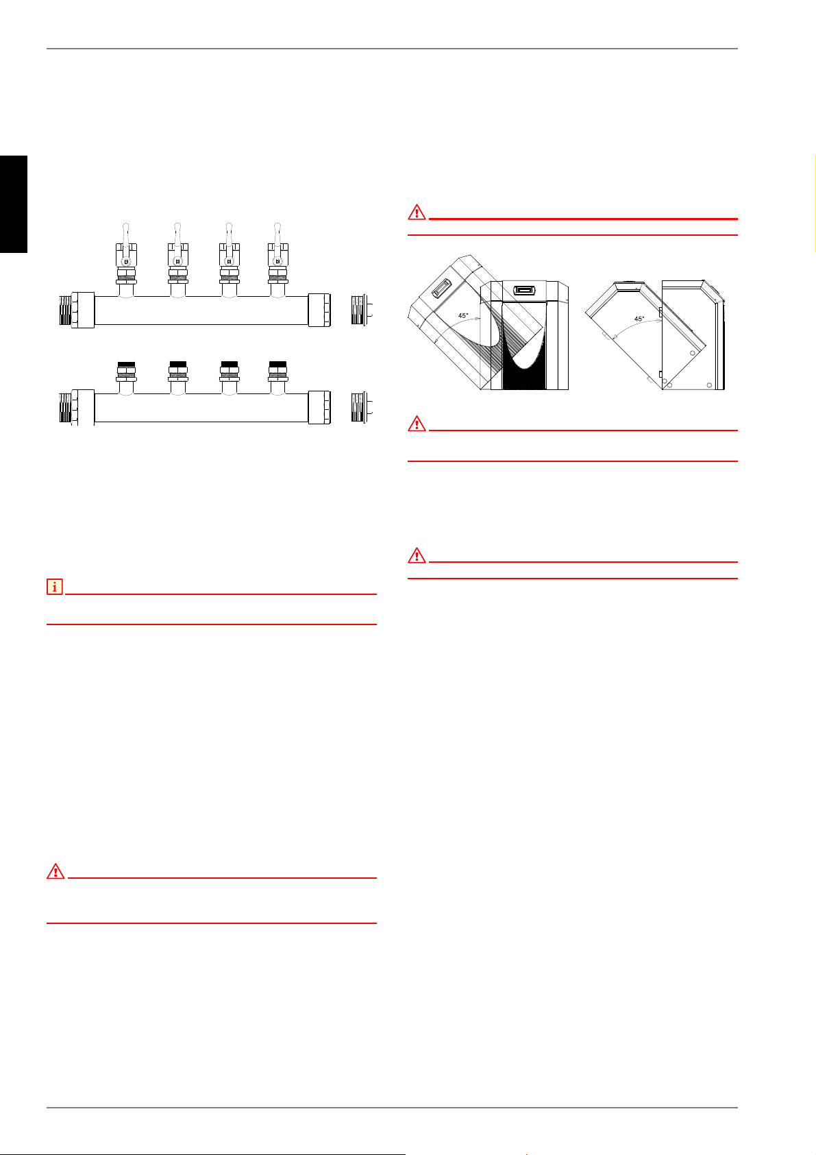
Die Wärmepumpe ist nicht an der Palette befestigt.
ACHTUNG!
Die Wärmepumpe darf nur bis zu einer Neigung von maximal 45° (in jeder
Richtung) gekippt werden.
ACHTUNG!
Gerät nicht an den Bohrungen in den Verkleidungsblechen anheben!
ACHTUNG!
Vor Anschluss der Wärmepumpe Heizungsanlage spülen.
ACHTUNG!
Der maximale Prüfdruck beträgt heiz- und soleseitig 6,0 bar(ü). Dieser
Wert darf nicht überschritten werden.
ACHTUNG!
Im Wärmequelleneintritt der Wärmepumpe ist der beiliegende
Schmutzfänger zu montieren, um den Verdampfer gegen
Verunreinigungen zu schützen.
ACHTUNG!
Die Sole muss mindestens zu 25 % aus einem Frostschutz auf
Monoethylenglykol- oder Propylenglykolbasis bestehen und ist vor dem
Befüllen zu mischen.
ACHTUNG!
Rechtsdrehfeld beachten: Bei falscher Verdrahtung wird das Anlaufen
der Wärmepumpe verhindert. Ein entsprechender Warnhinweis wird im
Wärmepumpenmanager angezeigt (Verdrahtung anpassen).
ACHTUNG!
Es ist nicht zulässig über einen Relaisausgang mehr als eine elektronisch
geregelte Umwälzpumpe zu schalten.
ACHTUNG!
Die Inbetriebnahme der Wärmepumpe muss gemäß der Montage- und
Gebrauchsanweisung des Wärmepumpenmanagers erfolgen.
ACHTUNG!
Arbeiten an der Wärmepumpe dürfen nur vom autorisierten und
sachkundigen Kundendienst durchgeführt werden.
ACHTUNG!
Vor Öffnen des Gerätes sind alle Stromkreise spannungsfrei zu schalten.
1.2 Bestimmungsgemäßer
Gebrauch
Dieses Gerät ist nur für den vom Hersteller vorgesehenen Ver-
wendungszweck freigegeben. Ein anderer oder darüber hinaus
gehender Gebrauch gilt als nicht bestimmungsgemäß. Dazu
zählt auch die Beachtung der zugehörigen Projektierungsunter-
lagen. Änderungen oder Umbauten am Gerät sind zu unterlas-
sen.
1.3 Gesetzliche Vorschriften und
Richtlinien
Diese Wärmepumpe ist gemäß Artikel 1, Abschnitt 2 k) der EG-
Richtlinie 2006/42/EC (Maschinenrichtlinie) für den Gebrauch im
häuslichen Umfeld bestimmt und unterliegt damit den Anforde-
rungen der EG-Richtlinie 2006/95/EC (Niederspannungsrichtli-
nie). Sie ist damit ebenfalls für die Benutzung durch Laien zur
Beheizung von Läden, Büros und anderen ähnlichen Arbeitsum-
gebungen, von landwirtschaftlichen Betrieben und von Hotels,
Pensionen und ähnlichen oder anderen Wohneinrichtungen vor-
gesehen.
Die Wärmepumpe entspricht allen relevanten DIN-/VDE-Vor-
schriften und EG-Richtlinien. Diese können der CE-Erklärung im
Anhang entnommen werden.
Der elektrische Anschluss der Wärmepumpe muss nach den gül-
tigen VDE-, EN- und IEC-Normen ausgeführt werden. Zusätzlich
sind die Anschlussbedingungen der Versorgungsunternehmen
zu beachten.
Die Wärmepumpe ist entsprechend den einschlägigen Vorschrif-
ten in die Wärmequellen- und Heizungsanlage einzubinden.
Personen, insbesondere Kinder, die aufgrund ihrer physischen,
sensorischen oder geistigen Fähigkeiten oder ihrer Unerfahren-
heit oder Unkenntnis nicht in der Lage sind, das Gerät sicher zu
benutzen, sollten dieses Gerät nicht ohne Aufsicht oder Anwei-
sung durch eine verantwortliche Person benutzen.
Kinder sollten beaufsichtigt werden, um sicher zu stellen, dass
sie nicht mit dem Gerät spielen.
ACHTUNG!
Für den Betrieb und die Wartung einer Wärmepumpe sind die rechtlichen
Anforderungen des Landes einzuhalten, in dem die Wärmepumpe
betrieben wird. Je nach Kältemittelfüllmenge ist die Dichtheit der
Wärmepumpe in regelmäßigen Abständen durch entsprechend
geschultes Personal zu überprüfen und zu protokollieren.
1.4 Energiesparende Handhabung
der Wärmepumpe
Durch das Betreiben dieser Wärmepumpe tragen Sie zur Scho-
nung unserer Umwelt bei. Für den effizienten Betrieb ist eine
sorgfältige Bemessung der Heizungsanlage und der Wärme-
quelle sehr wichtig. Dabei ist besonderes Augenmerk auf mög-
lichst niedrige Wasservorlauftemperaturen zu richten. Darum
sollten alle angeschlossenen Energieverbraucher für niedrige
Vorlauftemperaturen geeignet sein. Eine um 1 K höhere Heiz-
wassertemperatur steigert den Energieverbrauch um ca. 2,5 %.
Eine Niedertemperaturheizung mit Vorlauftemperaturen zwi-
schen 30 °C und 50 °C ist für einen energiesparenden Betrieb
gut geeignet.
www.dimplex.de 452235.66.05 · FD 9310 DE-3
Deutsch
SI 6TU - SI 18TU
2 Verwendungszweck der
Wärmepumpe
2.1 Anwendungsbereich
Die Sole/Wasser-Wärmepumpe ist ausschließlich für die Erwär-
mung von Heizungswasser vorgesehen. Sie kann in vorhande-
nen oder neu zu errichtenden Heizungsanlagen eingesetzt wer-
den. Als Wärmeträger in der Wärmequellenanlage dient ein
Gemisch aus Wasser und Frostschutz (Sole). Als Wärmequel-
lenanlage können Erdsonden, Erdkollektoren oder ähnliche An-
lagen genutzt werden.
2.2 Arbeitsweise
Das Erdreich speichert Wärme die von Sonne, Wind und Regen
eingebracht wird. Diese Erdwärme wird im Erdkollektor, der Erd-
sonde oder ähnlichem von der Sole bei niedriger Temperatur
aufgenommen. Eine Umwälzpumpe fördert dann die "erwärmte"
Sole in den Verdampfer der Wärmepumpe. Dort wird diese
Wärme an das Kältemittel im Kältekreislauf abgegeben. Dabei
kühlt sich die Sole wieder ab, so dass sie im Solekreis wieder
Wärmeenergie aufnehmen kann.
Das Kältemittel wird vom elektrisch angetriebenen Verdichter an-
gesaugt, verdichtet und auf ein höheres Temperaturniveau "ge-
pumpt". Die bei diesem Vorgang zugeführte elektrische Antriebs-
leistung geht nicht verloren, sondern wird größtenteils dem
Kältemittel zugeführt.
Daraufhin gelangt das Kältemittel in den Verflüssiger und über-
trägt hier wiederum seine Wärmeenergie an das Heizwasser.
Abhängig vom Betriebspunkt erwärmt sich so das Heizwasser
auf bis zu 62 °C.
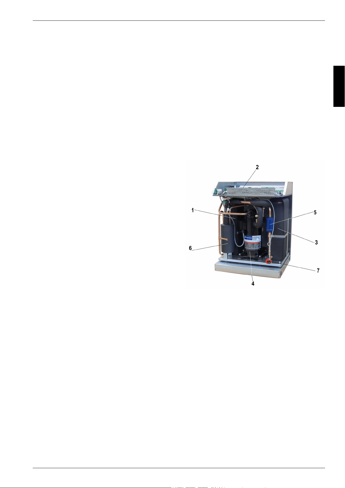
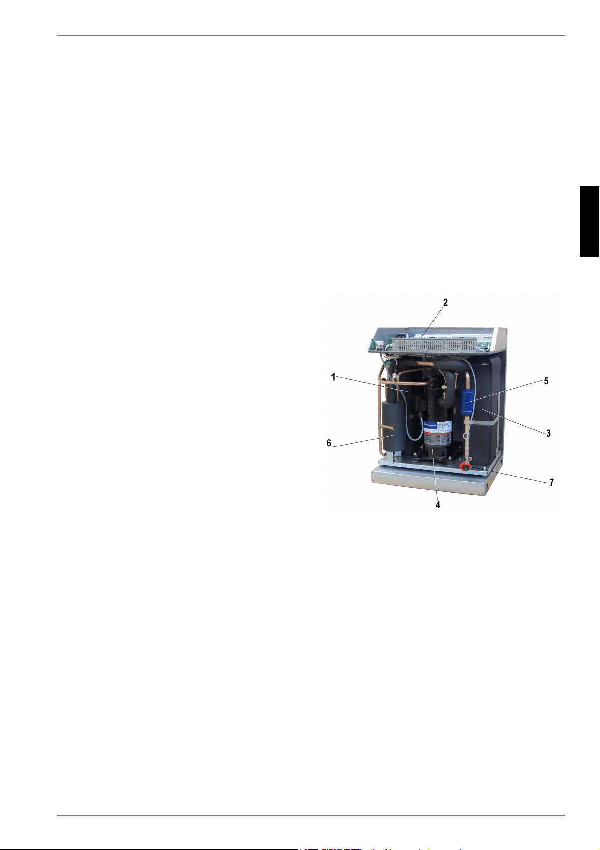
3 Grundgerät
Das Grundgerät besteht aus einer anschlussfertigen Wärme-
pumpe für Innenaufstellung mit Blechgehäuse, Schaltkasten und
integriertem Wärmepumpenmanager. Der Kältekreis ist „herme-
tisch geschlossen“ und enthält das vom Kyoto-Protokoll erfasste
fluorierte Kältemittel R410A mit einem GWP-Wert von 1975. Es
ist FCKW-frei, baut kein Ozon ab und ist nicht brennbar.
Am Schaltblech sind alle für den Betrieb der Wärmepumpe not-
wendigen Bauteile angebracht. Ein Fühler für die Außentempe-
ratur mit Befestigungsmaterial sowie ein Schmutzfänger liegen
der Wärmepumpe bei. Die Zuleitung für Last- und Steuerspan-
nung ist bauseits zu verlegen.
Die Zuleitung der bauseits zu stellenden Solepumpe ist am
Schaltblech anzuschließen. Dabei ist - falls erforderlich - für
diese ein Motorschutz bzw. Schütz vorzusehen.
Die Wärmequellenanlage mit Soleverteiler ist bauseits zu erstel-
len.
1) Verflüssiger
2) Schaltblech
3) Verdampfer
4) Verdichter
5) Filtertrockner
6) Economizer
7) Expansionsventil
DE-4 452235.66.05 · FD 9310 www.dimplex.de
Deutsch
SI 6TU - SI 18TU
4 Zubehör
4.1 Soleverteiler
Der Soleverteiler vereinigt die Kollektorschleifen der Wärmequel-
lenanlage zu einer Hauptleitung, welche an die Wärmepumpe
angeschlossen wird. Mittels der integrierten Kugelhähne können
zum Entlüften einzelne Solekreise abgesperrt werden.
4.2 Fernbedienung
Als Komforterweiterung ist im Sonderzubehör eine Fernbe-
dienstation erhältlich. Bedienung und Menüführung sind iden-
tisch mit denen des Wärmepumpenmanagers. Der Anschluss er-
folgt über eine Schnittstelle (Sonderzubehör) mit Westernstecker
RJ 12.
HINWEIS
Bei Heizungsreglern mit abnehmbarem Bedienteil kann dieses direkt als
Fernbedienstation genutzt werden.
4.3 Gebäudeleittechnik
Der Wärmepumpenmanager kann durch die Ergänzung der je-
weiligen Schnittstellen-Steckkarte an ein Netzwerk eines Gebäu-
deleitsystems angeschlossen werden. Für den genauen An-
schluss und die Parametrierung der Schnittstelle muss die
ergänzende Montageanweisung der Schnittstellenkarte beachtet
werden.
Für den Wärmepumpenmanager sind folgende Netzwerkverbin-
dungen möglich:
Modbus
EIB, KNX
Ethernet
ACHTUNG!
Bei einer externen Ansteuerung der Wärmepumpe bzw. der
Umwälzpumpen ist ein Durchflussschalter vorzusehen, der das
Einschalten des Verdichters bei fehlendem Volumenstrom verhindert.
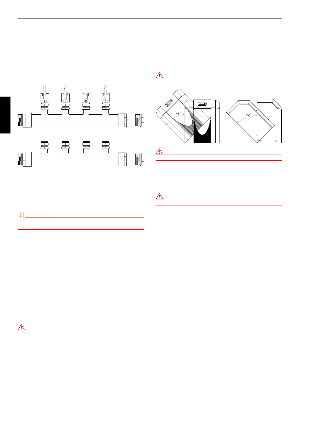
5 Transport
Zum Transport auf ebenem Untergrund eignet sich ein Hubwa-
gen. Muss die Wärmepumpe auf unebenem Untergrund oder
über Treppen befördert werden, kann dies mit Tragriemen ge-
schehen. Diese können direkt unter der Palette hindurchgeführt
werden.
ACHTUNG!
Die Wärmepumpe ist nicht an der Palette befestigt.
ACHTUNG!
Die Wärmepumpe darf nur bis zu einer Neigung von maximal 45° (in jeder
Richtung) gekippt werden.
Zum Anheben des Gerätes ohne Palette sind die seitlich im Rah-
men vorgesehenen Bohrungen zu benutzen. Die seitlichen Ver-
kleidungsbleche sind dabei abzunehmen. Als Tragehilfe kann
ein handelsübliches Rohr dienen.
ACHTUNG!
Gerät nicht an den Bohrungen in den Verkleidungsblechen anheben!
www.dimplex.de 452235.66.05 · FD 9310 DE-5
Deutsch
SI 6TU - SI 18TU
6 Aufstellung
6.1 Allgemeine Hinweise
Die Sole/Wasser-Wärmepumpe muss in einem frostfreien und
trockenen Raum auf einer ebenen, glatten und waagerechte Flä-
che aufgestellt werden. Dabei sollte der Rahmen rundum dicht
am Boden anliegen, um eine ausreichende Schallabdichtung zu
gewährleisten. Werden Stellfüße verwendet, ist die Wärme-
pumpe waagrecht auszurichten. In diesem Fall kann sich der an-
gegebene Schallpegel um bis zu 3 dB(A) erhöhen und zusätzli-
che schalldämmende Maßnahmen notwendig werden.
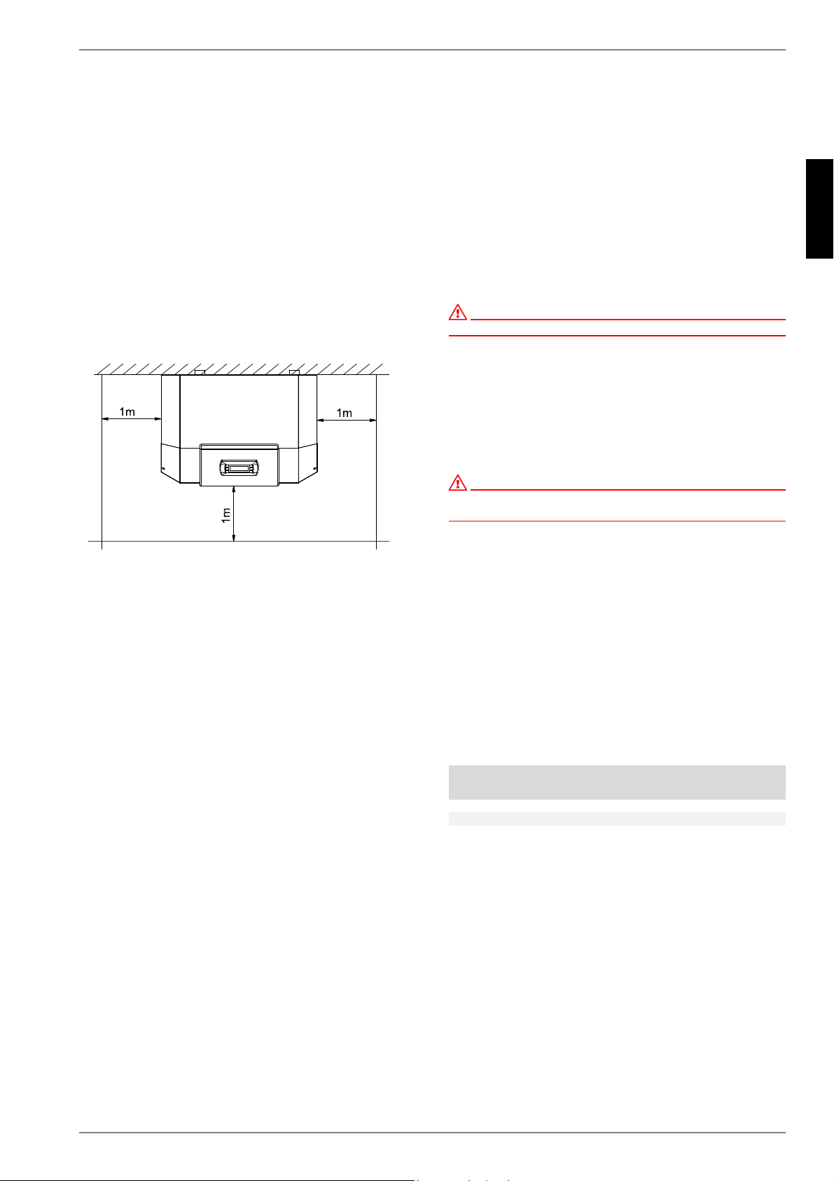
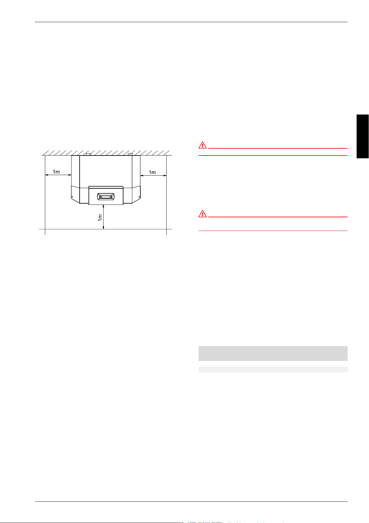
Die Wärmepumpe muss so aufgestellt sein, dass ein Kunden-
diensteinsatz problemlos durchgeführt werden kann. Dies ist ge-
währleistet, wenn ein Abstand von ca. 1 m vor und neben der
Wärmepumpe eingehalten wird.
Im Aufstellraum dürfen zu keiner Jahreszeit Frost oder höhere
Temperaturen als 35 °C auftreten.
6.2 Schallemissionen
Aufgrund der wirkungsvollen Schallisolation arbeitet die Wärme-
pumpe sehr leise. Eine Schallübertragung auf das Funda-
ment bzw. auf das Heizsystem wird durch interne Entkopplungs-
maßnahmen weitgehend verhindert.
7Montage
7.1 Allgemein
An der Wärmepumpe sind folgende Anschlüsse herzustellen:
Vor-/Rücklauf Sole (Wärmequellenanlage)
Vor-/Rücklauf Heizung
Temperaturfühler
Spannungsversorgung
7.2 Heizungsseitiger Anschluss
ACHTUNG!
Vor Anschluss der Wärmepumpe Heizungsanlage spülen.
Bevor die heizwasserseitigen Anschlüsse der Wärmepumpe er-
folgen, muss die Heizungsanlage gespült werden, um eventuell
vorhandene Verunreinigungen, Reste von Dichtmaterial oder
ähnliches, zu entfernen. Ein Ansammeln von Rückständen im
Verflüssiger kann zum Totalausfall der Wärmepumpe führen.
Nach erstellter heizungsseitiger Installation ist die Heizungsan-
lage zu füllen, zu entlüften und abzudrücken.
ACHTUNG!
Der maximale Prüfdruck beträgt heiz- und soleseitig 6,0 bar(ü).
Dieser Wert darf nicht überschritten werden.
Beim Füllen der Anlage ist folgendes zu beachten:
unbehandeltes Füll- und Ergänzungswasser muss Trink-
wasserqualität haben
(farblos, klar, ohne Ablagerungen)
das Füll- und Ergänzungswasser muss vorfiltriert sein (Po-
renweite max. 5 µm).
Eine Steinbildung in Warmwasserheizungsanlagen kann nicht
vollständig vermieden werden, ist aber bei Anlagen mit Vorlauf-
temperaturen kleiner 60 °C vernachlässigbar gering.
Bei Mittel- und Hochtemperatur-Wärmepumpen können auch
Temperaturen über 60 °C erreicht werden.
Daher sollten für das Füll- und Ergänzungswasser nach VDI
2035 Blatt 1 folgende Richtwerte eingehalten werden:
Gesamtheiz-
leistung in [kW]
Summe Erdalkalien
in mol/m³ bzw.
mmol/l
Gesamt-
härte in °dH
bis 200
2,0 11,2
200 bis 600
1,5 8,4
> 600 < 0,02 < 0,11
DE-6 452235.66.05 · FD 9310 www.dimplex.de
Deutsch
SI 6TU - SI 18TU
Mindestheizwasserdurchsatz
Der Mindestheizwasserdurchsatz der Wärmepumpe ist in jedem
Betriebszustand der Heizungsanlage sicherzustellen. Dieses
kann z.B. durch Installation eines doppelt differenzdrucklosen
Verteilers oder eines Überströmventiles erreicht werden. Die
Einstellung eines Überströmventiles ist in Kapitel Inbetrieb-
nahme erklärt.
HINWEIS
Der Einsatz eines Überströmventils ist nur bei Flächenheizungen und
einem max. Heizwasserdurchsatz von 1,3 m³/h ratsam. Bei Nichtbeachten
kann es zu Störungen der Anlage führen.
Sofern Wärmepumpenmanager und Heizungsumwälzpumpen
betriebsbereit sind, arbeitet die Frostschutzfunktion des Wärme-
pumpenmanagers. Bei Außerbetriebnahme der Wärmepumpe
oder Stromausfall ist die Anlage zu entleeren. Bei Wärmepum-
penanlagen, an denen ein Stromausfall nicht erkannt werden
kann (Ferienhaus), ist der Heizungskreis mit einem geeigneten
Frostschutz zu betreiben.
7.3 Wärmequellenseitiger
Anschluss
Folgende Vorgehensweise ist beim Anschluss einzuhalten:
Die Soleleitung am Vor- und Rücklauf Wärmequelle der Wärme-
pumpe anschließen. Dabei ist das hydraulische Einbindungs-
schema zu beachten.
ACHTUNG!
Im Wärmequelleneintritt der Wärmepumpe ist der beiliegende
Schmutzfänger zu montieren, um den Verdampfer gegen
Verunreinigungen zu schützen.
Die Sole ist vor dem Befüllen der Anlage herzustellen. Die Sole-
konzentration muss mindestens 25 % betragen. Das gewährleis-
tet Frostsicherheit bis -14 °C.
Es dürfen nur Frostschutzmittel auf Monoethylenglykol- oder
Propylenglykolbasis verwendet werden.
Die Wärmequellenanlage ist zu entlüften und auf Dichtheit zu
prüfen.
ACHTUNG!
Die Sole muss mindestens zu 25 % aus einem Frostschutz auf
Monoethylenglykol- oder Propylenglykolbasis bestehen und ist vor dem
Befüllen zu mischen.
HINWEIS
Bei Bedarf kann der Einsatzbereich bis zu einer Soleeintrittstemperatur
von -10 °C erweitert werden. In diesem Fall ist die minimale
Solekonzentration auf 30 % anzupassen. (Einfriertemperatur -17 °C)
ACHTUNG!
Der maximale Prüfdruck beträgt heiz- und soleseitig 6,0 bar(ü). Dieser
Wert darf nicht überschritten werden.
HINWEIS
Im Wärmequellenkreis ist ein geeigneter Luftabscheider
(Mikroluftblasenabscheider) bauseits vorzusehen.
7.4 Temperaturfühler
Folgende Temperaturfühler sind bereits eingebaut bzw. müssen
zusätzlich montiert werden:
Außentemperatur (R1) beigelegt (NTC-2)
Rücklauftemperatur Heizkreis (R2) eingebaut (NTC-10)
Rücklauftemperatur Primärkreis (R24) eingebaut (NTC-10)
Vorlauftemperatur Heizkreis (R9 ) eingebaut (NTC-10)
Vorlauftemperatur Primärkreis (R6) eingebaut (NTC-10)
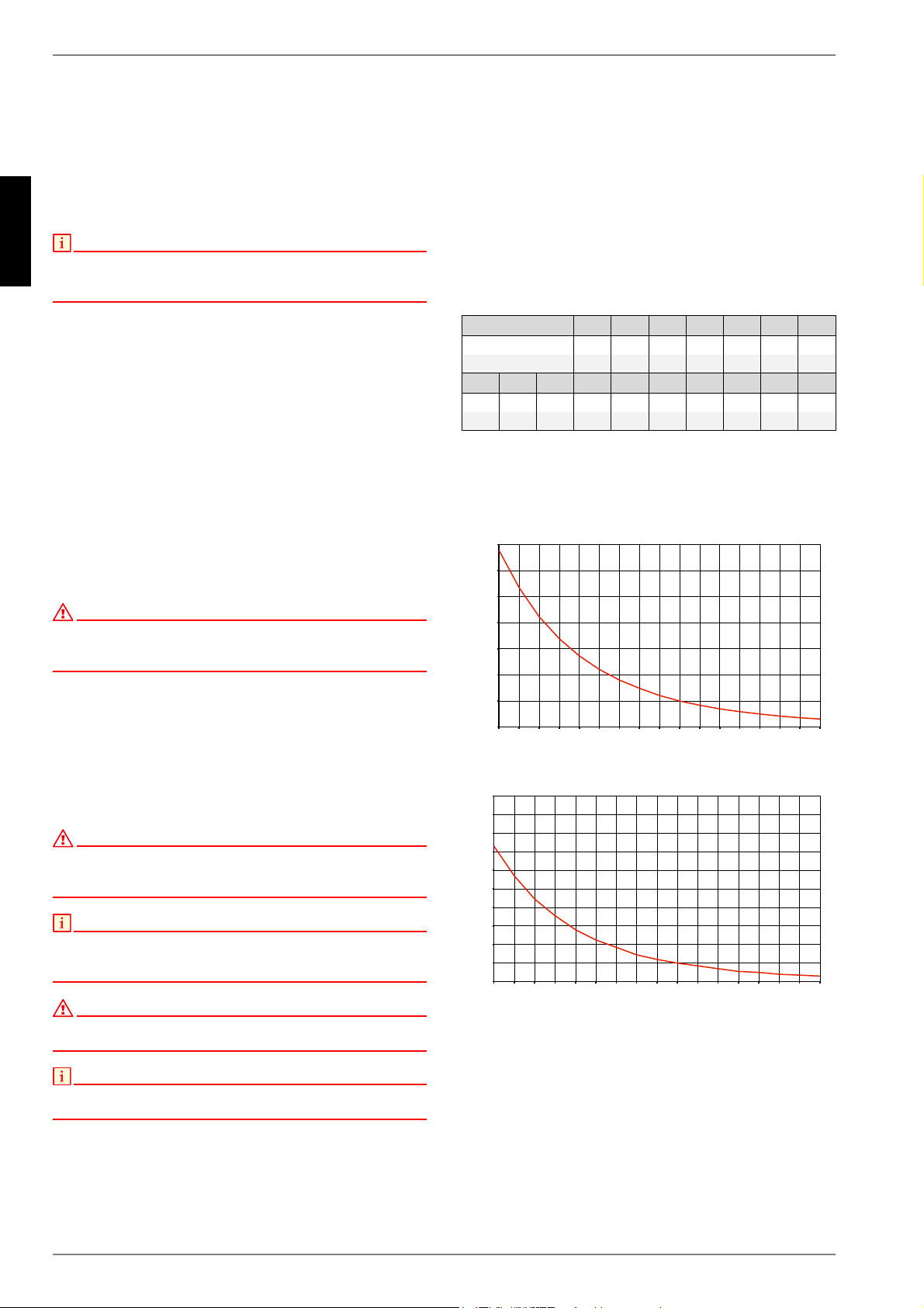
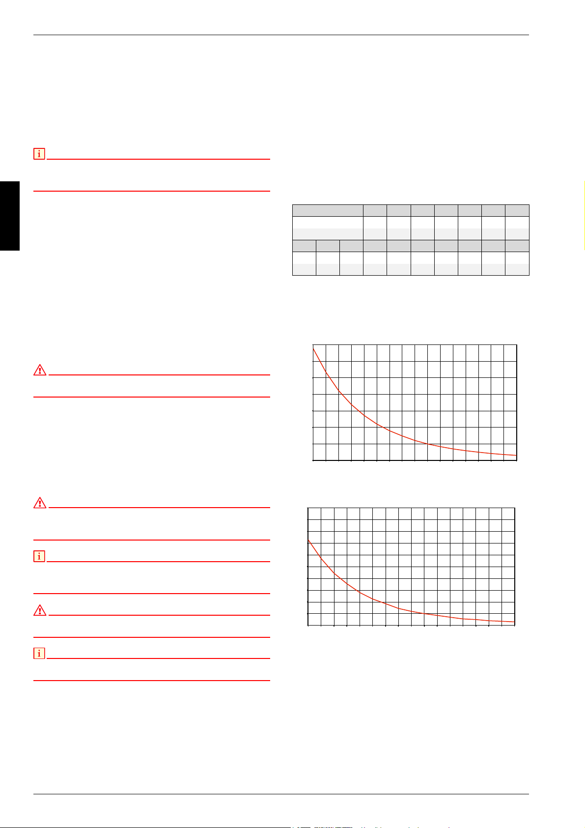
7.4.1 Fühlerkennlinien
Die an den Wärmepumpenmanager anzuschließenden Tempe-
raturfühler müssen der in Abb. 7.1 auf S. 6 gezeigten Fühler-
kennlinie entsprechen. Einzige Ausnahme ist der im Lieferum-
fang der Wärmepumpe befindliche Außentemperaturfühler
(siehe Abb. 7.2 auf S. 6)
Abb. 7.1:Fühlerkennlinie NTC 10
Abb. 7.2:Fühlerkennlinie NTC-2 nach DIN 44574 Außentemperaturfühler
Temperatur in °C
-20 -15 -10 -5 0 5 10
NTC-2 in k 14,6 11,4 8,9 7,1 5,6 4,5 3,7
NTC-10 in k 67,7 53,4 42,3 33,9 27,3 22,1 18,0
15 20 25 30 35 40 45 50 55 60
2,9 2,4 2,0 1,7 1,4 1,1 1,0 0,8 0,7 0,6
14,9 12,1 10,0 8,4 7,0 5,9 5,0 4,2 3,6 3,1
$XHQWHPSHUDWXU>&@
:LGHUVWDQGVZHUW>N2KP@
$XHQWHPSHUDWXU>&@
:LGHUVWDQGVZHUW>N2KP@
www.dimplex.de 452235.66.05 · FD 9310 DE-7
Deutsch
SI 6TU - SI 18TU
7.4.2 Montage des
Außentemperaturfühlers
Der Temperaturfühler muss so angebracht werden, dass sämtli-
che Witterungseinflüsse erfasst werden und der Messwert nicht
verfälscht wird.
an der Außenwand eines beheizten Wohnraumes und mög-
lichst an der Nord- bzw. Nordwestseite anbringen
nicht in „geschützter Lage“ (z.B. in einer Mauernische oder
unter dem Balkon) montieren
nicht in der Nähe von Fenstern, Türen, Abluftöffnungen, Au-
ßenleuchten oder Wärmepumpen anbringen
zu keiner Jahreszeit direkter Sonneneinstrahlung aussetzen
Fühlerleitung: Länge max. 40 m; Adernquerschnitt min.
0,75 mm²; Außendurchmesser des Kabels 4-8 mm.
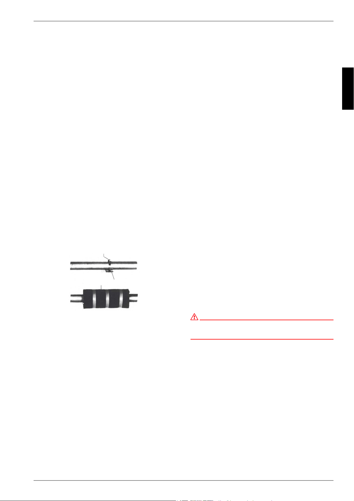
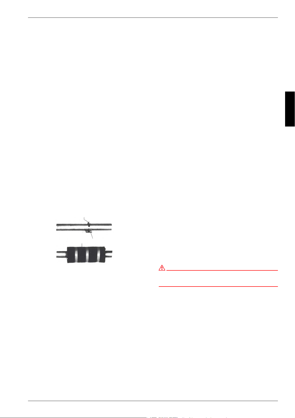
7.4.3 Montage der Anlegefühler
Die Montage der Anlegefühler ist nur notwendig, falls diese im
Lieferumfang der Wärmepumpe enthalten, aber nicht eingebaut
sind.
Die Anlegefühler können als Rohranlegefühler montiert oder in
die Tauchhülse des Kompaktverteilers eingesetzt werden.
Montage als Rohranlagefühler
Heizungsrohr von Lack, Rost und Zunder säubern
Gereinigte Fläche mit Wärmeleitpaste bestreichen (dünn
auftragen)
Fühler mit Schlauchschelle befestigen (gut festziehen, lose
Fühler führen zu Fehlfunktionen) und thermisch isolieren
7.4.4 Verteilsystem Hydraulik
Kompaktverteiler und Doppelt differenzdruckloser Verteiler fun-
gieren als Schnittstelle zwischen der Wärmepumpe, dem Hei-
zungsverteilsystem, dem Pufferspeicher und evtl. auch dem
Warmwasserspeicher. Dabei wird statt vieler Einzelkomponen-
ten ein kompaktes System verwendet, um die Installation zu ver-
einfachen. Weitere Informationen sind der jeweiligen Monta-
geanweisung zu entnehmen.
Kompaktverteiler
Der Rücklauffühler kann in der Wärmepumpe verbleiben oder ist
in die Tauchhülse einzubringen. Der noch vorhandene Hohlraum
zwischen Fühler und Tauchhülse muss mit Wärmeleitpaste voll-
ständig ausgefüllt sein.
Doppelt differenzdruckloser Verteiler
Der Rücklauffühler muss in die Tauchhülse des doppelt
differenzdrucklosen Verteilers eingebaut werden, um von den
Heizkreispumpen der Erzeuger- und Verbraucherkreise durch-
strömt zu werden.
7.5 Elektrischer Anschluss
7.5.1 Allgemein
Sämtliche elektrische Anschlussarbeiten dürfen nur von einer
Elektrofachkraft oder einer Fachkraft für festgelegte Tätigkeiten
unter Beachtung der
Montage- und Gebrauchsanweisung,
länderspezifischen Installationsvorschriften z.B. VDE 0100
technischen Anschlussbedingungen der Energieversorger-
und Versorgungsnetzbetreiber (z.B. TAB) und
örtlicher Gegebenheiten
durchgeführt werden.
Zur Gewährleistung der Frostschutzfunktion darf der Wärme-
pumpenmanager nicht spannungsfrei geschaltet werden und die
Wärmepumpe muss durchströmt werden.
Die Schaltkontakte der Ausgangsrelais sind entstört. Deshalb
wird abhängig vom Innenwiderstand eines Messinstruments
auch bei nicht geschlossenen Kontakten eine Spannung gemes-
sen, die aber weit unterhalb der Netzspannung liegt.
An den Regler-Klemmen N1-J1 bis N1-J11; N1-J19; N1-J20; N1-
J23 bis N1-J26 und der Klemmleiste X3; X5.1 liegt Kleinspan-
nung an. Wenn wegen eines Verdrahtungsfehlers an diese
Klemmen Netzspannung angelegt wird, wird der Wärmepum-
penmanager zerstört.
7.5.2 Elektrische Anschlussarbeiten
1) Die 4-adrige elektrische Versorgungsleitung für den Leis-
tungsteil der Wärmepumpe wird vom Stromzähler der Wär-
mepumpe über das EVU-Sperrschütz (falls gefordert) in die
Wärmepumpe geführt.
Anschluss der Lastleitung am Schaltblech der Wärme-
pumpe über Klemmen X1: L1/L2/L3/PE.
In der Leistungsversorgung für die Wärmepumpe ist eine all-
polige Abschaltung mit mindestens 3 mm Kontaktöffnungs-
abstand (z.B. EVU-Sperrschütz, Leistungsschütz), sowie
ein allpoliger Sicherungsautomat, mit gemeinsamer Auslö-
sung aller Außenleiter, vorzusehen (Auslösestrom und Cha-
rakteristik gemäß Geräteinformation).
ACHTUNG!
Rechtsdrehfeld beachten: Bei falscher Verdrahtung wird das Anlaufen
der Wärmepumpe verhindert. Ein entsprechender Warnhinweis wird im
Wärmepumpenmanager angezeigt (Verdrahtung anpassen).
2) Die 3-adrige elektrische Versorgungsleitung für den Wärme-
pumpenmanager (Heizungsregler N1) wird in die Wärme-
pumpe geführt.
Anschluss der Steuerleitung am Schaltblech der Wärme-
pumpe über Klemmen X2: L/N/PE.
Die Leistungsaufnahme der Wärmepumpe entnehmen Sie
der Produktinformation oder dem Typschild.
Die Versorgungsleitung (L/N/PE~230 V, 50 Hz) für den
WPM muss an Dauerspannung liegen und ist aus diesem
Grund vor dem EVU-Sperrschütz abzugreifen bzw. an den
Haushaltsstrom anzuschließen, da sonst während der EVU-
Sperre wichtige Schutzfunktionen außer Betrieb sind.
3) Das EVU-Sperrschütz (K22) mit 3 Hauptkontakten (1/3/5 //
2/4/6) und einem Hilfskontakt (Schließer 13/14) ist
entsprechend der Wärmepumpenleistung auszulegen und
bauseits beizustellen.
Der Schließer-Kontakt des EVU-Sperrschütz (13/14) wird
von Klemmleiste X3/G zur Steckerklemme X3/A1 geschleift.
VORSICHT! Kleinspannung!
6FKODXFKVFKHOOH
$QOHJHIKOHU
:lUPHLVROLHUXQJ

DE-8 452235.66.05 · FD 9310 www.dimplex.de
Deutsch
SI 6TU - SI 18TU
4) Das Schütz (K20) für den Tauchheizkörper (E10) ist bei mo-
noenergetischen Anlagen (2.WE) entsprechend der Heiz-
körperleistung auszulegen und bauseits beizustellen. Die
Ansteuerung (230 V AC) erfolgt aus dem Wärmepumpen-
manager über die Klemmen X2/N und X2/K20.
5) Das Schütz (K21) für die Flanschheizung (E9) im
Warmwasserspeicher ist entsprechend der
Heizkörperleistung auszulegen und bauseits beizustellen.
Die Ansteuerung (230 V AC) erfolgt aus dem WPM über die
Klemmen X2/N und X2/K21.
6) Die Schütze der Punkte 3;4;5 werden in die Elektrovertei-
lung eingebaut. Die Lastleitung für die eingebaute Rohrhei-
zung ist gemäß den gültigen Normen und Vorschriften aus-
zulegen und abzusichern.
7) Alle installierten elektrische Leitungen müssen als
dauerhafte und feste Verdrahtung ausgeführt sein.
8) Die Heizungsumwälzpumpe (M13) wird an den Klemmen
X2/N und X2/M13 angeschlossen.
9) Die Warmwasserladepumpe (M18) wird an den Klemmen
X2/N und X2/M18 angeschlossen.
10) Die Sole- bzw. Brunnenpumpe (M11) wird an den Klemmen
X2/N und X2/M11 und PE angeschlossen.
11) Bei der Wärmepumpen ist der Rücklauffühler integriert und
wird über die Steuerleitung zum Wärmepumpenmanager
geführt. Nur beim Einsatz eines Doppelt-Differenzdruck-
losen-Verteilers muss der Rücklauffühler in der Tauch-
hülse im Verteiler eingebaut werden. Dann werden die Ein-
zeladern an den Klemmen X3/GND und X3/R2.1
angeklemmt. Die Brücke A-R2, die im Auslieferzustand
zwischen X3/B2 und X3/1 sitzt, muss anschließend auf
die Klemmen X3/1 und X3/2 versetzt werden.
12) Der Außenfühler (R1) wird an den Klemmen X3/GND und
X3/R1 angeklemmt.
13) Der Warmwasserfühler (R3) liegt dem Warmwasserspei-
cher bei und wird an den Klemmen X3/GND und X3/R3 an-
geklemmt.
7.5.3 Anschluss von elektronisch
geregelten Umwälzpumpen
Elektronisch geregelte Umwälzpumpen weisen hohe Anlauf-
ströme auf, die unter Umständen die Lebenszeit des Wärme-
pumpenmanagers verkürzen können. Aus diesem Grund, ist zwi-
schen dem Ausgang des Wärmepumpenmanagers und der
elektronisch geregelten Umwälzpumpe ein Koppelrelais zu in-
stallieren bzw. installiert. Dies ist nicht erforderlich, wenn der zu-
lässige Betriebsstrom von 2 A und ein maximaler Anlaufstrom
von 12 A der elektronisch geregelten Umwälzpumpe nicht über-
schritten wird, oder es liegt eine ausdrückliche Freigabe des
Pumpenherstellers vor.
ACHTUNG!
Es ist nicht zulässig über einen Relaisausgang mehr als eine elektronisch
geregelte Umwälzpumpe zu schalten.
8 Inbetriebnahme
8.1 Allgemeine Hinweise
Um eine ordnungsgemäße Inbetriebnahme zu gewährleisten,
sollte diese von einem vom Werk autorisierten Kundendienst
durchgeführt werden. Unter bestimmten Bedingungen ist damit
eine Verlängerung der Gewährleistung verbunden (vgl. Garan-
tieleistungen).
8.2 Vorbereitung
Vor der Inbetriebnahme müssen folgende Punkte geprüft wer-
den:
Alle Anschlüsse der Wärmepumpe müssen, wie in Kapitel 7
beschrieben, montiert sein.
Die Wärmequellenanlage und der Heizkreis müssen gefüllt
und geprüft sein.
Der Schmutzfänger muss im Soleeintritt der Wärmepumpe
eingebaut sein.
Im Sole- und Heizkreis müssen alle Schieber, die den kor-
rekten Fluss behindern könnten, geöffnet sein.
Der Wärmepumpenmanager muss gemäß seiner Ge-
brauchsanweisung auf die Heizungsanlage abgestimmt
sein.
8.3 Vorgehensweise bei
Inbetriebnahme
Die Inbetriebnahme der Wärmepumpe erfolgt über den Wärme-
pumpenmanager.
ACHTUNG!
Die Inbetriebnahme der Wärmepumpe muss gemäß der Montage- und
Gebrauchsanweisung des Wärmepumpenmanagers erfolgen.
Wird der Mindestheizwasserdurchsatz mittels Überströmventil
sichergestellt, so ist dieses auf die Heizungsanlage abzustim-
men. Eine falsche Einstellung kann zu verschiedenen Fehlerbil-
dern und einem erhöhten elektrischen Energiebedarf führen. Um
das Überströmventil richtig einzustellen, empfehlen wir folgende
Vorgehensweise:
Schließen Sie alle Heizkreise, die auch im Betrieb je nach Nut-
zung geschlossen sein können, so dass der vom Wasserdurch-
satz ungünstigste Betriebs-zustand vorliegt. Dies sind in der
Regel die Heizkreise der Räume auf der Süd- und Westseite.
Mindestens ein Heizkreis muss geöffnet bleiben (z.B. Bad).
Das Überströmventil ist so weit zu öffnen, dass sich bei der aktu-
ellen Wärmequellentemperatur die in der unten stehenden Ta-
belle angegebene maximale Temperaturspreizung zwischen
Heizungsvor- und Rücklauf ergibt. Die Temperaturspreizung ist
möglichst nahe an der Wärmepumpe zu messen. Bei monoener-
getischen Anlagen ist der Heizstab während der Inbetriebnahme
zu deaktivieren.
www.dimplex.de 452235.66.05 · FD 9310 DE-9
Deutsch
SI 6TU - SI 18TU
9 Pflege / Reinigung
9.1 Pflege
Um Betriebsstörungen durch Schmutzablagerungen in den Wär-
metauschern zu vermeiden, ist dafür Sorge zu tragen, dass kei-
nerlei Verschmutzungen in die Wärmequellen- und Heizungsan-
lage gelangen können. Sollte es dennoch zu derartigen
Betriebsstörungen kommen, ist die Anlage wie unten angegeben
zu reinigen.
9.2 Reinigung Heizungsseite
Sauerstoff kann im Heizwasserkreis, insbesondere bei Verwen-
dung von Stahlkomponenten, Oxidationsprodukte (Rost) bilden.
Dieser gelangt über Ventile, Umwälzpumpen oder Kunststoff-
rohre in das Heizsystem. Deshalb sollte – besonders bei den
Rohren der Fußbodenheizung – auf eine diffusionsdichte Instal-
lation geachtet werden.
HINWEIS
Zur Vermeidung von Ablagerungen (z.B. Rost) im Kondensator der
Wärmepumpe wird empfohlen, ein geeignetes Korrosionsschutzsystem
einzusetzen.
Auch Reste von Schmier- und Dichtmitteln können das Heizwas-
ser verschmutzen.
Sind die Verschmutzungen so stark, dass sich die Leistungsfä-
higkeit des Verflüssigers in der Wärmepumpe verringert, muss
ein Installateur die Anlage reinigen.
Nach heutigem Kenntnisstand empfehlen wir, die Reinigung mit
einer 5%-igen Phosphorsäure oder, falls häufiger gereinigt wer-
den muss, mit einer 5%-igen Ameisensäure durchzuführen.
In beiden Fällen sollte die Reinigungsflüssigkeit Raumtempera-
tur haben. Es ist empfehlenswert, den Wärmeaustauscher ent-
gegen der normalen Durchflussrichtung zu spülen.
Um zu verhindern, dass säurehaltiges Reinigungsmittel in den
Heizungsanlagenkreislauf gelangt, empfehlen wir, das Spülgerät
direkt an den Vor- und Rücklauf des Verflüssigers anzuschlie-
ßen. Danach muss mit geeigneten neutralisierenden Mitteln
gründlich nachgespült werden, um Beschädigungen durch even-
tuell im System verbliebene Reinigungsmittelreste zu verhin-
dern.
Die Säuren sind mit Vorsicht anzuwenden und es sind die Vor-
schriften der Berufsgenossenschaften einzuhalten.
Die Herstellerangaben des Reinigungsmittels sind in jedem Fall
zu beachten.
9.3 Reinigung Wärmequellenseite
ACHTUNG!
Im Wärmequelleneintritt der Wärmepumpe ist der beiliegende
Schmutzfänger zu montieren, um den Verdampfer gegen
Verunreinigungen zu schützen.
Einen Tag nach der Inbetriebnahme sollte das Filtersieb des
Schmutzfängers gereinigt werden. Weitere Kontrollen sind je
nach Verschmutzung festzulegen. Sind keine Verunreinigungen
mehr erkennbar, kann das Sieb des Schmutzfängers ausgebaut
werden, um die Druckverluste zu reduzieren.
10 Störungen / Fehlersuche
Diese Wärmepumpe ist ein Qualitätsprodukt und sollte störungs-
frei arbeiten. Tritt dennoch eine Störung auf, wird diese im Dis-
play des Wärmepumpenamanagers angezeigt. Schlagen Sie
dazu auf der Seite Störungen und Fehlersuche in der Ge-
brauchsanweisung des Wärmepumpenmanagers nach.
Wenn die Störung nicht selbst behoben werden kann, verständi-
gen Sie bitte den zuständigen Kundendienst.
ACHTUNG!
Arbeiten an der Wärmepumpe dürfen nur vom autorisierten und
sachkundigen Kundendienst durchgeführt werden.
ACHTUNG!
Vor Öffnen des Gerätes sind alle Stromkreise spannungsfrei zu schalten.
11 Außerbetriebnahme /
Entsorgung
Bevor die Wärmepumpe ausgebaut wird, ist die Maschine span-
nungsfrei zu schalten und abzuschiebern. Der Ausbau der Wär-
mepumpe muss durch Fachpersonal erfolgen. Umweltrelevante
Anforderungen, in Bezug auf Rückgewinnung, Wiederverwen-
dung und Entsorgung von Betriebsstoffen und Bauteilen gemäß
den gängigen Normen, sind einzuhalten. Dabei ist besonders
Wert auf eine fachgerechte Entsorgung des Kältemittels und Käl-
teöles zu legen.
Wärmequellen-
temperatur
max. Temperaturspreizung
zwischen Heizungsvor- und
Rücklauf
von bis
-5 °C 0 °C 10 K
1 °C 5 °C 11 K
6 °C 9 °C 12 K
10 °C 14 °C 13 K
15 °C 20 °C 14 K
21 °C 25 °C 15 K
DE-10 452235.66.05 · FD 9310 www.dimplex.de
Deutsch
SI 6TU - SI 18TU
12 Geräteinformation
1 Typ- und Verkaufsbezeichnung
SI 6TU SI 8TU SI 11TU
2Bauform
2.1 Ausführung Universal Universal Universal
2.2 Regler Intern Intern Intern
2.3 Wärmemengenzählung integriert integriert integriert
2.4 Aufstellungsort / Schutzart nach EN 60 529 Innen / IP 21 Innen / IP 21 Innen / IP 21
2.5 Leistungsstufen 111
3 Einsatzgrenzen
3.1 Heizwasser-Vorlauf
1
°C
1. Bei Bedarf kann der Einsatzbereich bis zu einer Soleeintrittstemperatur von -10 C° erweitert werden. In diesem Fall ist die minimale Solekonzentration auf 30% anzupassen. (Ein-
friertemperatur -17 C°). Bei Soleeintrittstemperaturen von -10 C° bis -5 C°, Vorlauftemperatur von 55 C° bis 62 C° steigend.
20 bis 62 ±2 20 bis 62 ±2 20 bis 62 ±2
3.2 Sole (Wärmequelle Heizen) °C
Frostschutzmittel
Minimale Solekonzentration (-13 °C Einfreirtemperatur)
1
-5
1
bis +25
2
Monoethylenglykol
25 %
1
2. Der Betrieb ist bis zu einer Soleeintrittstemperatur von +35°C möglich. Bei Soleeintrittstemperaturen von +25°C bis +35°C, Vorlauftempertur von 62°C bis 55°C fallend.
4 Leistungsangaben / Durchfluss
3
3. Diese Angaben charakterisieren die Größe und die Leistungsfähigkeit der Anlage nach EN 14511. Für wirtschaftliche und energetische Betrachtungen sind Bivalenzpunkt und
Regler zu berücksichtigen. Dabei bedeuten z.B. B0W55: Wärmequellentemperatur 0 °C und Heizwasser-Vorlauftemperatur 55 °C. Diese Angaben werden ausschließlich mit sau-
berem Wärmeübertragern erreicht. Hinweise zur Pflege, Inbetriebnahme und Betrieb sind den entsprechenden Abschnitten der Montage- und Gebrauchsanleitung zu entnehmen.
4.1 Heizwasserdurchfluss / interne Druckdifferenz
maximal
(EN14511) m³/h / Pa
minimal m³/h / Pa
1,05 / 5300
0,55 / 1500
1,4 / 7700
0,7 / 1900
1,9 / 10500
0,9 / 2400
4.2 Wärmeleistung / Leistungszahl EN 14511 EN 14511 EN 14511
bei B-5 / W45 kW / --- 5,0 / 3,1 6,5 / 3,2 9,1 / 3,2
bei B0 / W55 kW / --- 5,5 / 2,8 7,2 / 2,8 10,0 / 2,9
bei B0 / W45 kW / --- 5,8 / 3,6 7,5 / 3,6 10,4 / 3,7
bei B0 / W35 kW / --- 6,1 / 4,7 8,1 / 4,8 10,9 / 4,9
4.3 Schall-Leistungspegel nach EN 12102
4
dB(A)
4. Die angegebenen Schallwerte gelten ohne die optional erhältlichen Stellfüße. Bei Verwendung der Stellfüße kann sich der Pegel um bis zu 3db (A) erhöhen
46 46 47
4.4 Schall-Druckpegel in 1 m Entfernung
4
5
dB(A)
5. Der angegebene Schalldruckpegel entspricht dem Betriebsgeräusch der Wärmepumpe im Heizbetrieb bei 35 °C Vorlauftemperatur.
Der angegebene Schalldruckpegel stellt den Freifeldpegel dar. Je nach Aufstellungsort kann der Messwert um bis zu 16 dB (A) abweichen.
34 34 35
4.5 Soledurchsatz bei interner Druckdifferenz (Wärmequelle) m³/h / Pa 1,45 / 8700 1,9 / 11000 2,6 / 14000
5 Abmessungen / Anschlüsse und Gewicht
5.1 Geräteabmessungen ohne Anschlüsse
6
H x B x L cm
6. Beachten Sie, dass der Platzbedarf für Rohranschluss, Bedienung und Wartung größer ist.
845 x 650 x 565 845 x 650 x 565 845 x 650 x 565
5.2 Geräteanschlüsse für Heizung Zoll
G 1 1/4“ AG
7
7. flachdichtend
5.3 Geräteanschlüsse für Wärmequelle Zoll
G 1 1/4“ AG
7
5.4 Gewicht der Transporteinheit(en) incl. Verpackung kg 119 128 134
5.5 Kältemittel / Gesamt-Füllgewicht Typ / kg R410A / 2,5 R410A / 2,9 R410A / 3,3
5.6 Schmiermittel / Gesamt-Füllmenge Typ / Liter Polyolester (POE)/ 0,7 Polyolester (POE)/ 1,2 Polyolester (POE)/ 1,2
6 Elektrischer Anschluss
6.1 Lastspannung / Absicherung V / A 3~ / PE 400V (50Hz) / C10A
6.2 Steuerspannung / Absicherung V / A 1~ / N / PE 230V (50Hz) / C13A
6.3 Nennaufnahme B0 / W35
3
/ max. Aufnahme kW
1,30 / 2,6 1,67 / 3,2 2,22 / 4,3
6.4 Anlaufstrom m. Sanftanlasser A 28 (ohne Sanftanlasser) 17 20
6.5 Nennstrom B0 / W35 / cos A / --- 2,35 / 0,8 3,01 / 0,8 4,01 / 0,8
7 Entspricht den europäischen
Sicherheitsbestimmgungen
8
8. siehe CE-Konformitätserklärung
8 8
8 Sonstige Ausführungsmerkmale
8.1 Wasser im Gerät gegen Einfrieren geschützt
9
9. Die Heizungsumwälzpumpe und der Wärmepumpenmanager müssen betriebsbereit sein.
ja ja ja
8.2 max. Betriebsüberdruck (Wärmequelle/Wärmesenke) 3,0 3,0 3,0

www.dimplex.de 452235.66.05 · FD 9310 DE-11
Deutsch
SI 6TU - SI 18TU
1 Typ- und Verkaufsbezeichnung
SI 14TU SI 18TU
2Bauform
2.1 Ausführung Universal Universal
2.2 Regler Intern Intern
2.3 Wärmemengenzählung integriert integriert
2.4 Aufstellungsort / Schutzart nach EN 60 529 Innen / IP 21 Innen / IP 21
2.5 Leistungsstufen 1 1
3 Einsatzgrenzen
3.1 Heizwasser-Vorlauf
1
°C
1. Bei Bedarf kann der Einsatzbereich bis zu einer Soleeintrittstemperatur von -10 C° erweitert werden. In diesem Fall ist die minimale Solekonzentration auf 30% anzupassen. (Ein-
friertemperatur -17 C°). Bei Soleeintrittstemperaturen von -10 C° bis -5 C°, Vorlauftemperatur von 55 C° bis 62 C° steigend.
20 bis 62 ±2 20 bis 62 ±2
3.2 Sole (Wärmequelle Heizen) °C
Frostschutzmittel
Minimale Solekonzentration (-13 °C Einfreirtemperatur)
1
-5
1
bis +25
2
Monoethylenglykol
25 %
1
2. Der Betrieb ist bis zu einer Soleeintrittstemperatur von +35°C möglich. Bei Soleeintrittstemperaturen von +25°C bis +35°C, Vorlauftempertur von 62°C bis 55°C fallend.
-5
1
bis +25
2
Monoethylenglykol
25 %
1
4 Leistungsangaben / Durchfluss
3
3. Diese Angaben charakterisieren die Größe und die Leistungsfähigkeit der Anlage nach EN 14511. Für wirtschaftliche und energetische Betrachtungen sind Bivalenzpunkt und
Regler zu berücksichtigen. Dabei bedeuten z.B. B0W55: Wärmequellentemperatur 0 °C und Heizwasser-Vorlauftemperatur 55 °C. Diese Angaben werden ausschließlich mit sau-
berem Wärmeübertragern erreicht. Hinweise zur Pflege, Inbetriebnahme und Betrieb sind den entsprechenden Abschnitten der Montage- und Gebrauchsanleitung zu entnehmen.
4.1 Heizwasserdurchfluss / interne Druckdifferenz
maximal
(EN14511) m³/h / Pa
minimal m³/h / Pa
2,4 / 10700
1,2 / 2700
3,0 / 18000
1,5 / 4500
4.2 Wärmeleistung / Leistungszahl EN 14511 EN 14511
bei B-5 / W45 kW / --- 11,5 / 3,3 14,9 / 3,2
bei B0 / W55 kW / --- 12,8 / 3,0 16,5 / 2,9
bei B0 / W45 kW / --- 13,3 / 3,8 17,0 / 3,6
bei B0 / W35 kW / --- 13,9 / 5,0 17,5 / 4,7
4.3 Schall-Leistungspegel nach EN 12102
4
dB(A)
4. Die angegebenen Schallwerte gelten ohne die optional erhältlichen Stellfüße. Bei Verwendung der Stellfüße kann sich der Pegel um bis zu 3db (A) erhöhen.
47 50
4.4 Schall-Druckpegel in 1 m Entfernung
4
5
dB(A)
5. Der angegebene Schalldruckpegel entspricht dem Betriebsgeräusch der Wärmepumpe im Heizbetrieb bei 35 °C Vorlauftemperatur.
Der angegebene Schalldruckpegel stellt den Freifeldpegel dar. Je nach Aufstellungsort kann der Messwert um bis zu 16 dB (A) abweichen.
35 38
4.5 Soledurchsatz bei interner Druckdifferenz (Wärmequelle) m³/h / Pa 3,4 / 14000 4,3 / 21500
5 Abmessungen / Anschlüsse und Gewicht
5.1 Geräteabmessungen ohne Anschlüsse
6
H x B x L cm
6. Beachten Sie, dass der Platzbedarf für Rohranschluss, Bedienung und Wartung größer ist.
845 x 650 x 565 845 x 650 x 665
5.2 Geräteanschlüsse für Heizung Zoll
G 1 1/4“ AG
7
7. flachdichtend
G 1 1/4“ AG
7
5.3 Geräteanschlüsse für Wärmequelle Zoll
G 1 1/4“ AG
7
G 1 1/2“ AG
7
5.4 Gewicht der Transporteinheit(en) incl. Verpackung kg 140 163
5.5 Kältemittel / Gesamt-Füllgewicht Typ / kg R410A / 4,4 R410A / 5,2
5.6 Schmiermittel / Gesamt-Füllmenge Typ / Liter Polyolester (POE)/ 1,2 Polyolester (POE)/ 1,9
6 Elektrischer Anschluss
6.1 Lastspannung / Absicherung V / A 3~ / PE 400V (50Hz) / C13A 3~ / PE 400V (50Hz) / C16A
6.2 Steuerspannung / Absicherung V / A 1~ / N / PE 230V (50Hz) / C13A 1~ / N / PE 230V (50Hz) / C13A
6.3 Nennaufnahme B0 / W35
3
/ max. Aufnahme kW
2,78 / 5,4 3,72 / 7,2
6.4 Anlaufstrom m. Sanftanlasser A 23 28
6.5 Nennstrom B0 / W35 / cos A / --- 5,02 / 0,8 6,71 / 0,8
7 Entspricht den europäischen
Sicherheitsbestimmgungen
8
8. siehe CE-Konformitätserklärung
8
8 Sonstige Ausführungsmerkmale
8.1 Wasser im Gerät gegen Einfrieren geschützt
9
9. Die Heizungsumwälzpumpe und der Wärmepumpenmanager müssen betriebsbereit sein.
ja ja
8.2 max. Betriebsüberdruck (Wärmequelle/Wärmesenke) 3,0 3,0

DE-12 452235.66.05 · FD 9310 www.dimplex.de
Deutsch
SI 6TU - SI 18TU
13 Garantieurkunde
Glen Dimplex Deutschland GmbH
Garantieurkunde Systemtechnik
(Heizungs-Wärmepumpen, Zentrale Wohnungslüftungs-
geräte) gültig für Deutschland und Österreich
(Ausgabestand 04/2012)
Die nachstehenden Bedingungen, die Voraussetzungen und
Umfang unserer Garantieleistung umschreiben, lassen die Ge-
währleistungsverpflichtungen des Verkäufers aus dem Kaufver-
trag mit dem Endabnehmer unberührt. Für die Geräte leisten wir
Garantie gemäß nachstehenden Bedingungen:
Wir beheben unentgeltlich nach Maßgabe der folgenden Bedin-
gungen Mängel am Gerät, die auf einem Material-und/ oder Her-
stellungsfehler beruhen, wenn sie uns unverzüglich nach Fest-
stellung und innerhalb von 24 Monaten nach Lieferung an den
Erstendabnehmer gemeldet werden. Bei gewerblichem Ge-
brauch innerhalb von 12 Monaten.
Dieses Gerät fällt nur dann unter diese Garantie, wenn es von
einem Unternehmer in einem der Mitgliedstaaten der Europäi-
schen Union gekauft wurde, es bei Auftreten des Mangels in
Deutschland oder Österreich betrieben wird und Garantieleistun-
gen auch in Deutschland oder Österreich erbracht werden kön-
nen.
Die Behebung der von uns als garantiepflichtig anerkannter
Mängel geschieht dadurch, dass die mangelhaften Teile unent-
geltlich nach unserer Wahl instandgesetzt oder durch einwand-
freie Teile ersetzt werden. Durch Art oder Ort des Einsatzes des
Gerätes oder schlechte Zugänglichkeit des Gerätes bedingte au-
ßergewöhnliche Kosten der Nachbesserung werden nicht über-
nommen. Der freie Gerätezugang muß durch den Endabnehmer
gestellt werden. Ausgebaute Teile, die wir zurücknehmen, gehen
in unser Eigentum über. Die Garantiezeit für Nachbesserungen
und Ersatzteile endet mit dem Ablauf der ursprünglichen Garan-
tiezeit für das Gerät. Die Garantie erstreckt sich nicht auf leicht
zerbrechliche Teile, die den Wert oder die Gebrauchstauglichkeit
des Gerätes nur unwesentlich beeinträchtigen. Es ist jeweils der
Original-Kaufbeleg mit Kauf- und/oder Lieferdatum vorzulegen.
Eine Garantieleistung entfällt, wenn vom Endabnehmer oder
einem Dritten die entsprechenden VDE-Vorschriften, die Bestim-
mungen der örtlichen Versorgungsunternehmen oder unsere
Montage- und Gebrauchsanweisung sowie die in den Projektie-
rungsunterlagen enthaltenen Hinweise zu Wartungsarbeiten
oder Einbindungsschemen nicht beachtet worden sind oder
wenn unser funktionsnotwendiges Zubehör nicht eingesetzt
wurde. Durch etwa seitens des Endabnehmers oder Dritter un-
sachgemäß vorgenommenen Änderungen und Arbeiten, wird die
Haftung für die daraus entstehenden Folgen aufgehoben. Die
Garantie erstreckt sich auf das Gerät und vom Lieferer bezogene
Teile. Nicht vom Lieferer bezogene Teile und Geräte-/Anlagen-
mängel die auf nicht vom Lieferer bezogene Teile zurückzufüh-
ren sind fallen nicht unter den Garantieanspruch.
Bei endgültig fehlgeschlagener Nachbesserung wird der Herstel-
ler entweder kostenfreien Ersatz liefern oder den Minderwert ver-
güten. Im Falle einer Ersatzlieferung behalten wir uns die Gel-
tendmachung einer angemessenen Nutzungsanrechnung für die
bisherige Nutzungszeit vor. Weitergehende oder andere Ansprü-
che, insbesondere solche auf Ersatz außerhalb des Gerätes ent-
standener Schäden, sind ausgeschlossen.
Eine Verlängerung der Garantie auf 60 Monate für Heizungs-
Wärmepumpe und zentrale Wohnungslüftungsgeräte ab Inbe-
triebnahmedatum, jedoch maximal 72 Monate ab Auslieferung
Werk bzw. 78 Monate ab Fertigungsdatum, wird gemäß den
nachfolgenden Bedingungen gewährt: Voraussetzung für die
Übernahme der verlängerten Garantie ist eine kostenpflichtige
Inbetriebnahme durch den autorisierten Systemtechnik-Kunden-
dienst mit Inbetriebnahmeprotokoll innerhalb einer Betriebszeit
(Verdichterlaufzeit) von weniger als 150 Stunden. Die Beauftra-
gung der kostenpflichtigen Inbetriebnahme durch den System-
technik-Kundendienst erfolgt schriftlich mit dem entsprechenden
Auftragsformular oder mittels der Online-Beauftragung im Inter-
net (www.dimplex.de/garantieverlaengerung). Der Bestätigung
der Garantiezeitverlängerung vorausgesetzt, ist die vollständige
Bezahlung der Inbetriebnahmepauschale und die Beseitigung
etwaiger, im Feld Bemerkungen des Inbetriebnahmeprotokolls,
vermerkter Mängel. Die Bestätigung der Garantiezeitverlänge-
rung erfolgt von unten angegebener Adresse nach erfolgreichem
Abschluss der Inbetriebnahme und der Einreichung des
Inbetriebnahmeprotokolls durch den Systemtechnik-Kunden-
dienst.
Die Inbetriebnahmepauschale beinhaltet die eigentliche Inbe-
triebnahme und die Fahrtkosten. Es wird keine Haftung für die
ordnungsgemäße Planung, Dimensionierung und Ausführung
der Gesamtanlage übernommen. Die Behebung von Anlagen-
mängeln und Wartezeiten sind Sonderleistungen.
Die aktuellen Inbetriebnahmepauschalen und der in der Inbe-
triebnahmepauschale enthaltene Leistungsumfang sind im Inter-
net unter: www.dimplex.de/garantieverlaengerung hinterlegt.
Hier ist ebenfalls eine Online-Beauftragung integriert.
Glen Dimplex Deutschland GmbH
Geschäftsbereich Dimplex
Kundendienst Systemtechnik
Am Goldenen Feld 18 · 95326 Kulmbach
Für die Auftragsbearbeitung werden der Typ, die Erzeugnisnum-
mer E-Nr. bzw. Fabrikationsnummer Fabr.-Nr. oder Serien-
nummer S/N, das Fertigungsdatum FD und falls angegeben der
Kundendienstindex KI des Gerätes benötigt.
Diese Angaben befinden sich auf dem Typschild des Gerätes.
Kundendienstadresse:
Tel.-Nr.:
Fax.-Nr.:
E-Mail-Adresse:
Internet:
+49 (0) 9221 709 562
+49 (0) 9221 709 565
09221709565@glendimplex.de
09221709565@dimplex.de
www.dimplex.de
www.dimplex.de/serviceauftrag
www.dimplex.de/garantieverlängerung

www.dimplex.de 452235.66.05 · FD 9310 EN-1
English
SI 6TU - SI 18TU
Table of contents
1 Please Read Immediately .......................................................................................................... EN-2
1.1 Important Information........................................................................................................................... EN-2
1.2 Intended Use ....................................................................................................................................... EN-2
1.3 Legal Regulations and Directives ........................................................................................................ EN-2
1.4 Energy-Efficient Use of the Heat Pump ............................................................................................... EN-2
2 Purpose of the Heat Pump ........................................................................................................ EN-3
2.1 Application ........................................................................................................................................... EN-3
2.2 Operating Principle .............................................................................................................................. EN-3
3 Basic Device ............................................................................................................................... EN-3
4 Accessories ................................................................................................................................ EN-4
4.1 Brine Circuit Manifold........................................................................................................................... EN-4
4.2 Remote control .................................................................................................................................... EN-4
4.3 Building management technology........................................................................................................ EN-4
5 Transport..................................................................................................................................... EN-4
6 Set-up .......................................................................................................................................... EN-5
6.1 General Information ............................................................................................................................. EN-5
6.2 Acoustic Emissions.............................................................................................................................. EN-5
7 Installation .................................................................................................................................. EN-5
7.1 General Information ............................................................................................................................. EN-5
7.2 Heating System Connection ................................................................................................................ EN-5
7.3 Heat Source Connection...................................................................................................................... EN-6
7.4 Temperature sensor ............................................................................................................................ EN-6
7.5 Electrical connection............................................................................................................................ EN-7
8 Commissioning .......................................................................................................................... EN-8
8.1 General Information ............................................................................................................................. EN-8
8.2 Preparation .......................................................................................................................................... EN-8
8.3 Start-up Procedure .............................................................................................................................. EN-8
9 Maintenance and Cleaning ........................................................................................................ EN-9
9.1 Maintenance ........................................................................................................................................ EN-9
9.2 Cleaning the Heating System .............................................................................................................. EN-9
9.3 Cleaning the Heat Source System....................................................................................................... EN-9
10 Faults / Trouble-Shooting.......................................................................................................... EN-9
11 Decommissioning / Disposal .................................................................................................... EN-9
12 Device Information ................................................................................................................... EN-10
Anhang / Appendix / Annexes ............................................................................................................ A-I
Maßbilder / Dimension Drawings / Schémas cotés ...................................................................................A-II
Diagramme / Diagrams / Diagrammes ...................................................................................................... A-IV
Stromlaufpläne / Circuit Diagrams / Schémas électriques ...................................................................... A-X
Hydraulisches Einbindungsschema / Hydraulic integration diagram /
Schéma d'intégration hydraulique ......................................................................................................... A-XVII
Konformitätserklärung / Declaration of Conformity / Déclaration de conformité............................... A-XIX

EN-2 452235.66.05 · FD 9310 www.dimplex.de
English
SI 6TU - SI 18TU
1 Please Read
Immediately
1.1 Important Information
ATTENTION!
When operating or maintaining a heat pump, the legal requirements of the
country where the heat pump is operated apply. Depending on the
refrigerant quantity, the heat pump must be inspected for leaks at regular
intervals by a certified technician, and these inspections must be
recorded.
ATTENTION!
If the heat pump or circulating pump is controlled externally, an flow rate
switch is required to prevent the compressor from being switched on
when there is no volume flow.
ATTENTION!
The heat pump is not secured to the wooden pallet.
ATTENTION!
The heat pump must not be tilted more than 45° (in any direction).
ATTENTION!
Do not use the holes in the panel assemblies for lifting the device!
ATTENTION!
Flush the heating system prior to connecting the heat pump.
ATTENTION!
The maximum test pressure in the heating circuit and the brine circuit is
6.0 bar (ü). This value must not be exceeded.
ATTENTION!
The supplied dirt trap must be inserted in the heat source inlet of the heat
pump to protect the evaporator against the ingress of impurities.
ATTENTION!
The brine solution must contain at least a 25 % concentration of a
monoethylene glycol or propylene glycol-based antifreeze, which must
be mixed before filling.
ATTENTION!
Ensure that there is a clockwise rotating field: With incorrect wiring the
starting of the heat pump is prevented. A corresponding warning is
indicated on the display of the heat pump manager (adjust wiring).
ATTENTION!
It is not permitted to connect more than one electronically regulated
circulating pump via a relay output.
ATTENTION!
The heat pump must be started up in accordance with the installation and
operating instructions of the heat pump manager.
ATTENTION!
Any work on the heat pump may only be performed by authorised and
qualified after-sales service technicians.
ATTENTION!
Disconnect all electrical circuits from the power source prior to opening
the device.
1.2 Intended Use
This device is only intended for use as specified by the manufac-
turer. Any other use beyond that intended by the manufacturer is
prohibited. This requires the user to abide by the relevant project
planning documents. Please refrain from tampering with or alte-
ring the device.
1.3 Legal Regulations and
Directives
This heat pump is designed for use in a domestic environment
according to Article 1, Paragraph 2 k) of EC directive 2006/42/EC
(machinery directive) and is thus subject to the requirements of
EC directive 2006/95/EC (low-voltage directive). It is thus also in-
tended for use by non-professionals for heating shops, offices
and other similar working environments, in agricultural establish-
ments and in hotels, guest houses and similar / other residential
buildings.
This heat pump conforms to all relevant DIN/VDE regulations
and EU directives. Refer to the EC Declaration of Conformity in
the appendix for details.
The heat pump must be connected to the power supply in com-
pliance with all relevant VDE, EN and IEC standards. Any further
connection requirements stipulated by local utility companies
must also be observed.
The heat pump is to be connected to the heat source system and
the heating system in accordance with all applicable regulations.
Persons, especially children, who are not capable of operating
the device safely due to their physical, sensory or mental abilities
or their inexperience or lack of knowledge, must not operate this
device without supervision or instruction by the person in charge.
Children must be supervised to ensure that they do not play with
the device.
ATTENTION!
When operating or maintaining a heat pump, the legal requirements of the
country where the heat pump is operated apply. Depending on the
refrigerant quantity, the heat pump must be inspected for leaks at regular
intervals by a certified technician, and these inspections must be
recorded.
1.4 Energy-Efficient Use of the
Heat Pump
By operating this heat pump you are helping to protect our envi-
ronment. Both the heating system and the heat source must be
properly designed and dimensioned to ensure efficient operation.
It is particularly important to keep water flow temperatures as low
as possible. All connected energy consumers should therefore
be suitable for low flow temperatures. Raising the heating water
temperature by 1 K corresponds to an increase in energy con-
sumption of approx.
2.5 %. Low-temperature heating systems with flow temperatures
between 30 °C and 50 °C are particularly well-suited for energy-
efficient operation.
www.dimplex.de 452235.66.05 · FD 9310 EN-3
English
SI 6TU - SI 18TU
2 Purpose of the Heat
Pump
2.1 Application
The brine-to-water heat pump is to be used exclusively for the
heating of heating water. It can be used in new or previously ex-
isting heating systems. A mixture of water and antifreeze (brine)
is used as the heat transfer medium in the heat source system.
Borehole heat exchangers, ground heat collectors or similar sys-
tems can be used as the heat source system.
2.2 Operating Principle
The heat generated by the sun, wind and rain is stored in the
ground. This heat stored in the ground is collected at a low tem-
perature by the brine circulating in the ground collector, ground
coil or similar device. A circulating pump then conveys the
“heated” brine to the evaporator of the heat pump. There the heat
is given off to the refrigerant in the refrigerating cycle. This cools
the brine so that it can once again absorb thermal energy in the
brine circuit.
The refrigerant is drawn in by the electrically driven compressor,
compressed and “pumped” to a higher temperature level. The
electrical power needed to run the compressor is not lost in this
process. Most of it is absorbed by the refrigerant.
Subsequently, the refrigerant is passed through the condenser
where it transfers its heat energy to the heating water. Depend-
ing on the set operating point (thermostat setting), the heating
water is thus heated up to a max. of 62 °C.
3 Basic Device
The basic device consists of a ready-to-use heat pump for indoor
installation, complete with sheet metal casing, control panel and
integrated manager. The refrigerant circuit is hermetically
sealed. It contains the Kyoto protocol approved refrigerant
R410A with a GWP value of 1975. It is CFC-free, does not de-
plete ozone and is non-flammable.
All components required for the operation of the heat pump are
located on the control panel. An external temperature sensor in-
cluding fixing accessories and a dirt trap are supplied with the
heat pump. The supply for the load current and the control volt-
age must be installed by the customer.
The supply lead of the brine circulating pump (to be provided by
the customer) must be connected to the control panel. If re-
quired, a motor protection device and/or contactor must be pro-
vided here.
The customer must provide both the heat source system and the
brine circuit manifold.
1) Liquifier
2) Control panel
3) Evaporator
4) Compressor
5) Filter dryer
6) Economizer
7) Expansion valve
EN-4 452235.66.05 · FD 9310 www.dimplex.de
English
SI 6TU - SI 18TU
4 Accessories
4.1 Brine Circuit Manifold
The brine circuit manifold merges the individual collector loops of
the heat source system into a single main pipe which is con-
nected to the heat pump. Integrated ball valves allow the individ-
ual brine circuits to be shut off for de-aeration purposes.
4.2 Remote control
A remote control adds convenience and is available as a special
accessory. Operation and menu navigation are identical to those
of the heat pump manager. Connection takes place via an inter-
face (special accessories) with RJ 12 Western plug..
NOTE
In the case of heating controllers with a removable operating element,
this can also be used directly as a remote control.
4.3 Building management
technology
The heat pump manager can be connected to a building man-
agement system network via supplementation of the relevant in-
terface plug-in card. The supplementary installation instructions
of the interface card must be consulted regarding the exact con-
nection and parameterisation of the interface.
The following network connections can be made on the heat
pump manager:
Modbus
EIB, KNX
Ethernet
ATTENTION!
If the heat pump or circulating pump is controlled externally, an flow rate
switch is required to prevent the compressor from being switched on
when there is no volume flow.
5 Transport
A lift truck is suited for transporting the unit on a level surface.
Carrying straps may be used if the heat pump needs to be trans-
ported on an uneven surface or carried up or down stairs. These
straps can be passed directly underneath the wooden pallet.
ATTENTION!
The heat pump is not secured to the wooden pallet.
ATTENTION!
The heat pump must not be tilted more than 45° (in any direction).
Use the holes provided in the sides of the frame to lift the unit
without the pallet. The side panel assemblies must be removed
for this purpose. Any commercially available length of pipe can
be used as a carrying aid.
ATTENTION!
Do not use the holes in the panel assemblies for lifting the device!
www.dimplex.de 452235.66.05 · FD 9310 EN-5
English
SI 6TU - SI 18TU
6Set-up
6.1 General Information
The brine-to-water heat pump must be installed in a frost-free,
dry room on an even, smooth and horizontal surface. The entire
frame should lie directly on the floor to ensure an adequate
soundproof seal. If supporting feet are used, the heat pump must
be installed horizontally. In this case, the specified sound level
can be up to 3 dB(A) higher, and additional sound insulation
measures may be necessary.
The heat pump must be installed so that maintenance work can
be carried out without hindrance. This can be ensured by main-
taining a clearance of approx. 1 m in front of and on each side of
the heat pump.
Neither frost nor temperatures higher than 35°C must occur in
the installation location at any time of the year.
6.2 Acoustic Emissions
The heat pump operates silently due to efficient sound insulation.
Internal insulation measures should be carried out to prevent vi-
brations from being transmitted to the foundation or to the heat-
ing system.
7 Installation
7.1 General Information
The following connections need to be established on the heat
pump:
Flow and return of the brine (heat source system)
Flow and return flow of the heating system
Temperature sensor
Voltage supply
7.2 Heating System Connection
ATTENTION!
Flush the heating system prior to connecting the heat pump.
Before connecting the heating water system to the heat pump,
the heating system must be flushed to remove any impurities,
residue from sealants, etc. Any accumulation of deposits in the
liquifier could cause the heat pump to completely break down.
Once the heating system has been installed, it must be filled, de-
aerated and pressure-tested.
ATTENTION!
The maximum test pressure in the heating circuit and the brine circuit is
6.0 bar (ü). This value must not be exceeded.
Consideration must be given to the following when filling the sys-
tem:
Untreated filling water and make-up water must be of drink-
ing water quality (colourless, clear, free from sediments)
Filling water and make-up water must be pre-filtered (pore
size max. 5 µm).
Scale formation in hot water heating systems cannot be com-
pletely avoided, but in systems with flow temperatures below
60 °C the problem can be disregarded.
With medium and high-temperature heat pumps, temperatures
above 60 °C can be reached.
The following standard values should therefore be adhered to
concerning the filling water and make-up water (according to VDI
2035 Sheet 1):
Total heat
output in [kW]
Total alkaline earths
in mol/m³ and/or
mmol/l
Total
hardness in °dH
up to 200
2.0 11.2
200 to 600
1.5 8.4
> 600 < 0.02 < 0.11
EN-6 452235.66.05 · FD 9310 www.dimplex.de
English
SI 6TU - SI 18TU
Minimum heating water flow rate
The minimum heating water flow rate through the heat pump
must be assured in all operating states of the heating sys-
tem. This can be accomplished, for example, by installing either
a dual differential pressureless manifold or an overflow valve.
The procedure for adjusting an overflow valve is described in the
Chapter Start-Up.
NOTE
The use of an overflow valve is only recommended for panel heating and
a max. heating water flow of 1.3 m³/h. System faults may result if this is
not observed.
The antifreeze function of the heat pump manager is active
whenever the heat pump manager and the heat circulating
pumps are ready for operation. If the heat pump is taken out of
service or in the event of a power failure, the system has to be
drained. The heating circuit should be operated with a suitable
antifreeze if heat pump systems are implemented in buildings
where a power failure can not be detected (holiday home).
7.3 Heat Source Connection
The following procedure must be observed when connecting the
heat source:
Connect the brine pipe to the heat pump flow and return. The hy-
draulic integration diagram must be adhered to.
ATTENTION!
The supplied dirt trap must be inserted in the heat source inlet of the heat
pump to protect the evaporator against the ingress of impurities.
The brine liquid must be produced prior to charging the system.
The liquid must have an antifreeze concentration of at least 25 %
to ensure frost protection down to -14 °C.
Only monoethylene glycol or propylene glycol-based antifreeze
may be used.
The heat source system must be de-aerated and checked for
leaks.
ATTENTION!
The brine solution must contain at least a 25 % concentration of a
monoethylene glycol or propylene glycol-based antifreeze, which must
be mixed before filling.
NOTE
If necessary, the operating range can be extended to a brine inlet
temperature of -10 °C. In this case, the minimum brine concentration
must be adjusted to 30 %. (Freezing temperature -17 °C)
ATTENTION!
The maximum test pressure in the heating circuit and the brine circuit is
6.0 bar (ü). This value must not be exceeded.
NOTE
A suitable de-aerator (micro bubble air separator) must be installed in the
heat source circuit by the customer.
7.4 Temperature sensor
The following temperature sensors are already installed or must
be installed additionally:
External temperature sensor (R1) supplied (NTC-2)
Return temperature heating circuit (R2) installed (NTC-10)
Return temperature primary circuit (R24) installed (NTC-10)
Flow temperature heating circuit (R9) installed (NTC-10)
Flow temperature primary circuit (R6) installed) (NTC-10)
7.4.1 Sensor characteristic curves
The temperature sensors to be connected to the heat pump ma-
nager must correspond to the sensor characteristic curve illustra-
ted in Fig.7.1 on pag. 6. The only exception is the external tem-
perature sensor included in the scope of supply of the heat pump
(see Fig.7.2 on pag. 6)
Fig. 7.1:Sensor characteristic curve NTC 10
Fig. 7.2:Sensor characteristic curve, standardised NTC-2 ac-
cording to DIN 44574 External temperature sensor
Temperature in °C -20 -15 -10 -5 0 5 10
NTC-2 in k 14.6 11.4 8.9 7.1 5.6 4.5 3.7
NTC-10 in k 67.7 53.4 42.3 33.9 27.3 22.1 18.0
15 20 25 30 35 40 45 50 55 60
2.9 2.4 2.0 1.7 1.4 1.1 1.0 0.8 0.7 0.6
14.9 12.1 10.0 8.4 7.0 5.9 5.0 4.2 3.6 3.1
([WHUQDOWHPSHUDWXUHLQ>&@
5HVLVWDQFHYDOXHLQ>N2KP@
([WHUQDOWHPSHUDWXUHLQ>&@
5HVLVWDQFHYDOXHLQ>N2KP@
www.dimplex.de 452235.66.05 · FD 9310 EN-7
English
SI 6TU - SI 18TU
7.4.2 Mounting the external
temperature sensor
The temperature sensor must be mounted in such a way that all
weather conditions are taken into consideration and the meas-
ured value is not falsified.
On the external wall of a heated room used as living space,
if possible on the north or north-west side of the building
Do not install in a “sheltered position” (e.g. in a wall niche or
under a balcony)
Not in the vicinity of windows, doors, exhaust air vents, ex-
ternal lighting or heat pumps
Not to be exposed to direct sunlight at any time of year
Sensor lead: Max. length 40 m; min. core cross-section
0.75 mm²; external diameter of the cable 4-8 mm.
7.4.3 Installing the strap-on sensor
It is only necessary to mount the strap-on sensors if they are in-
cluded in the scope of supply of the heat pump but have not yet
been installed.
The strap-on sensors can be fitted as pipe-mounted sensors or
installed in the immersion sleeve of the compact manifold.
Mounting as a pipe-mounted sensor
Remove paint, rust and scale from heating pipe.
Coat the cleaned surface with heat transfer compound
(apply sparingly).
Attach the sensor with a hose clip (tighten firmly, as loose
sensors can cause malfunctions) and thermally insulate.
7.4.4 Hydraulic distribution system
The compact manifold and the dual differential pressureless
manifold function as an interface between the heat pump, the
heating distribution system, the buffer tank and, in some cases,
even the hot water cylinder. A compact system is used to simplify
the installation process, so that a lot of different components do
not have to be installed individually. Further information can be
found in the relevant installation instructions.
Compact manifold
The return sensor can remain in the heat pump, or should be in-
stalled in the immersion sleeve. The remaining empty space be-
tween the sensor and the immersion sleeve must be filled com-
pletely with heat transfer compound.
dual differential pressureless manifold
In order for the heating circuit pumps of the generator and con-
sumer circuits to supply the flow to the return sensor, this must
be installed in the immersion sleeve of the dual differential pres-
sureless manifold.
7.5 Electrical connection
7.5.1 General
All electrical connection work must be carried out by a trained
electrician or a specialist for the specified tasks in accordance
with the
installation and operating instructions,
country-specific installation regulations (e.g. VDE 0100),
technical connection conditions of the energy suppliers and
supply grid operators (e.g. TAB) and
local conditions.
To ensure that the frost protection function of the heat pump
works properly, the heat pump manager must remain connected
to the power supply and the flow must be maintained through the
heat pump at all times.
The switching contacts of the output relay are interference-sup-
pressed. Therefore, depending on the internal resistance of the
measuring instrument, a voltage can also be measured when the
contacts are open. However, this will be much lower than the line
voltage.
Extra-low voltage is connected to controller terminals N1-J1 to
N1-J11; N1-J19; N1-J20; N1-J23 to N1-J26 and terminal strip
X3; X5.1. If, due to a wiring error, the line voltage is mistakenly
connected to these terminals, the heat pump manager will be de-
stroyed
7.5.2 Electrical installation
1) The supply electric cable for the output section of the heat
pump (up to 4-core) is fed from the electricity meter of the
heat pump via the utility blocking contactor (if required) into
the heat pump Connection of the mains cable to the control
panel of the heat pump via terminal X1: L1/L2/L3/PE.
An all-pole disconnecting device with a contact gap of at
least 3 mm (e.g. utility blocking contactor or power contac-
tor) and an all-pole circuit breaker with common tripping for
all external conductors must be installed in the power supply
for the heat pump (tripping current and characteristic in com-
pliance with the device information).
ATTENTION!
Ensure that there is a clockwise rotating field: With incorrect wiring the
starting of the heat pump is prevented. A corresponding warning is
indicated on the display of the heat pump manager (adjust wiring).
2) The three-core electric supply cable for the heat pump man-
ager (heating controller N1) is fed into the heat pump .
Connection of the control line to the control panel of the heat
pump via terminal X2: L/N/PE.
Details on the power consumption of the heat pump are
listed on both the product information sheet and the type
plate.
The (L/N/PE~230 V, 50 Hz) supply cable for the heat pump
manager must have a constant voltage. For this reason, it
should be tapped upstream from the utility blocking contac-
tor or be connected to the household current, as important
protection functions could otherwise be lost during a utility
block.
+RVHFOLS
6WUDSRQVHQVRU
7KHUPDOLQVXODWLRQ

EN-8 452235.66.05 · FD 9310 www.dimplex.de
English
SI 6TU - SI 18TU
3) The utility blocking contactor (K22) with 3 main contacts (1/
3/5 // 2/4/6) and an auxiliary contact (NO contact 13/14)
should be dimensioned according to the heat pump output
and must be supplied by the customer.
The NO contact of the utility blocking contactor (13/14) is
looped from terminal strip X3/G to connector terminal X3/A1.
CAUTION! Extra-low voltage!
4) The contactor (K20) for the immersion heater (E10) of mono
energy systems (HG2) should be dimensioned according to
the radiator output and must be supplied by the customer. It
is controlled (230 V AC) by the heat pump manager via ter-
minals X2/N and X2/K20.
5) The contactor (K21) for the flange heater (E9) in the hot
water cylinder should be dimensioned according to the radi-
ator output and must be supplied by the customer. It is con-
trolled (230 V AC) by the heat pump manager via terminals
X2/N and X2/K21.
6) The contactors mentioned above in points 3, 4 and 5 are in-
stalled in the electrical distribution system. The mains cable
for the installed pipe heater must be laid and secured in ac-
cordance with the valid standards and regulations.
7) All installed electric cables must have permanent wiring.
8) The heat circulating pump (M13) is connected to terminals
X2/N and X2/M13.
9) The DHW loading pump (M18) is connected to terminals X2/
N and X2/M18.
10) The brine or well pump (M11) is connected to terminalsX2/N
and X2/M11 and PE.
11) The return flow sensor is integrated into the heat pumps
and is connected to the heat pump manager via the control
line. The return flow sensor must be installed in the im-
mersion sleeve in the manifold only when a dual differen-
tial pressureless manifold is used. The single-core wires are
then connected to terminals X3/GND and X3/ R2.1. Bridge
A-R2 (situated between X3/B2 and X3/1 when delivered)
must then be moved to terminals X3/1 and X3/2.
12) The external sensor (R1) is connected to terminals X3/GND
and X3/R1.
13) The domestic hot water sensor (R3) is included with the do-
mestic hot water cylinder and is connected to terminals X3/
GND and X3/R3.
7.5.3 Connecting an electronically
regulated circulating pump
Electronically regulated circulating pumps have high starting cur-
rents, which may shorten the service life of the heat pump man-
ager. For this reason, a coupling relay is installed or must be in-
stalled between the output of the heat pump manager and the
electronically regulated circulating pump. This is not necessary if
the permissible operating current of 2 A and a maximum starting
current of 12 A are not exceeded in the electronically regulated
circulating pump or if express approval has been issued by the
pump manufacturer.
ATTENTION!
It is not permitted to connect more than one electronically regulated
circulating pump via a relay output.
8 Commissioning
8.1 General Information
To ensure that start-up is performed correctly, it should only be
carried out by an after-sales service technician authorised by the
manufacturer. These measures can also include an additional
warranty under certain conditions (see Warranty).
8.2 Preparation
The following items need to be checked prior to start-up:
The heat pump must be fully connected, as described in
Chapter 7.
The heat source system and the heating circuit must have
been filled and checked.
The dirt trap must be inserted in the brine inlet of the heat
pump.
All valves that could impair proper flow in the brine and heat-
ing circuits must be open.
The heat pump manager must be adapted to the heating
system in accordance with the controller’s operating instruc-
tions.
8.3 Start-up Procedure
The heat pump is started up via the heat pump manager.
ATTENTION!
The heat pump must be started up in accordance with the installation and
operating instructions of the heat pump manager.
If an overflow valve is fitted to assure the minimum heating water
flow rate, the valve must be set in accordance with the require-
ments of the respective heating system. Incorrect adjustment
can lead to faulty operation and increased energy consumption.
We recommend carrying out the following procedure to correctly
adjust the overflow valve:
Close all of the heating circuits that may also be closed during
operation (depending on the type of heat pump usage) so that
the most unfavourable operating state - with respect to the water
flow rate - is achieved. This normally means the heating circuits
of the rooms on the south and west sides of the building. At least
one heating circuit must remain open (e.g. bathroom).
The overflow valve should be opened far enough to produce the
maximum temperature spread between the heating flow and re-
turn flow listed in the table below for the current heat source tem-
perature. The temperature spread should be measured as close
as possible to the heat pump. The heating element of mono en-
ergy systems should be disconnected during start-up.
Heat source
temperature
Max. temperature spread
between heating flow and return
flow
From To
-5 °C 0 °C 10 K
1 °C 5 °C 11 K
6 °C 9 °C 12 K
10 °C 14 °C 13 K
15 °C 20 °C 14 K
21 °C 25 °C 15 K

www.dimplex.de 452235.66.05 · FD 9310 EN-9
English
SI 6TU - SI 18TU
9 Maintenance and
Cleaning
9.1 Maintenance
To prevent faults due to sediment in the heat exchangers, care
must be taken to ensure that no impurities can enter either the
heat source system or the heating system. In the event that op-
erating malfunctions due to contamination occur nevertheless,
the system should be cleaned as described below.
9.2 Cleaning the Heating System
The ingress of oxygen into the heating water circuit may result in
the formation of oxidation products (rust), particularly if steel
components are used. This oxygen enters the heating system via
the valves, the circulating pumps and/or plastic pipes. It is there-
fore essential - in particular with respect to the piping of under-
floor heating systems - that only diffusion-proof materials are
used.
NOTE
We recommend the installation of a suitable corrosion protection system
to prevent the formation of deposits (e.g. rust) in the condenser of the
heat pump.
Residue from lubricants and sealants may also contaminate the
heating water.
In the case of severe contamination leading to a reduction in the
performance of the liquifier in the heat pump, the system must be
cleaned by a heating technician.
Based on current information, we recommend using a 5 % phos-
phoric acid solution for cleaning purposes. However, if cleaning
needs to be performed more frequently, a 5 % formic acid solu-
tion should be used.
In either case, the cleaning fluid should be at room temperature.
We recommend flushing the heat exchanger in the direction op-
posite to the normal flow direction.
To prevent acidic cleaning agents from entering the heating sys-
tem circuit, we recommend connecting the flushing device di-
rectly to the flow and return flow of the liquifier. It is important that
the system be thoroughly flushed using appropriate neutralising
agents to prevent any damage from being caused by cleaning
agent residue remaining in the system.
Acids must be used with great care and all relevant regulations of
the employers’ liability insurance associations must be adhered
to.
The manufacturer's instructions regarding cleaning agent must
be complied with at all times.
9.3 Cleaning the Heat Source
System
ATTENTION!
The supplied dirt trap must be inserted in the heat source inlet of the heat
pump to protect the evaporator against the ingress of impurities.
The filter sieve of the dirt trap should be cleaned one day after-
start-up. Further checks must be set according to the level of
dirt.If no more signs of contamination are evident, the filter can
be removed to reduce pressure drops.
10 Faults / Trouble-
Shooting
This heat pump is a quality product and is designed for trouble-
free operation. In the event that a fault should occur, it will be in-
dicated on the heat pump manager display. Simply consult the
Faults and Trouble-Shooting page in the operating instructions of
the heat pump manager.
If you cannot correct the fault yourself, please contact your after-
sales service technician.
ATTENTION!
Any work on the heat pump may only be performed by authorised and
qualified after-sales service technicians.
ATTENTION!
Disconnect all electrical circuits from the power source prior to opening
the device.
11 Decommissioning /
Disposal
Before removing the heat pump, disconnect it from the power
source and close all valves. The deinstallation of the heat pump
must be performed by technical personnel. Observe all environ-
mentally-relevant requirements regarding the recovery, recycling
and disposal of materials and components in accordance with all
applicable standards. Particular attention should be paid to the
proper disposal of refrigerants and refrigeration oils.
EN-10 452235.66.05 · FD 9310 www.dimplex.de
English
SI 6TU - SI 18TU
12 Device Information
1 Type and order code
SI 6TU SI 8TU SI 11TU
2Design
2.1 Model Universal Universal Universal
2.2 controller Intern Intern Intern
2.3 Thermal energy metering Integreated Integreated Integreated
2.4 Installation location / degree of protection according to EN 60 529 Indoors / IP 21 Indoors / IP 21 Indoors / IP 21
2.5 Performance levels 111
3 Operating limits
3.1 Heating water flow
1
°C
1. If necessary, the operating range can be extended to a brine inlet temperature of -10 °C. In this case, the minimum brine concentration must be adjusted to 30%. (Freezing tem-
perature -17 C°). At brine inlet temperatures of -10 °C to -5 °C, flow temperature rising from 55 °C to 62 °C.
20 to 62 ± 20 to 62 ±2 20 to 62 ±2
3.2 Brine (heat source) °C
Antifreeze
Minimum brine concentration (-13 °C freezing temperature)
1
-5
1
to +25
2
Monoethyleneglycol
25 %
1
2. Operation is possible at brine inlet temperatures of up to + 35 °C. At brine inlet temperatures of +25 °C to +35 °C, flow temperature falling from 62 °C to 55 °C.
4 Performance data / flow rate
3
3. These data indicate the size and capacity of the system according to EN 14511. For an analysis of the economic and energy efficiency of the system, the bivalence point and
controller should be taken into consideration. The specified values have the following meaning, e.g. B0/W35: Heat source temperature 0 °C and heating water flow temperature
55 °C. These specifications can only be achieved with clean heat exchangers. Information on maintenance, start-up and operation can be found in the respective sections of the
installation and operating instructions.
4.1 Heating water flow rate at internal pressure differential
max.
(EN14511) m³/h / Pa
minimal m³/h / Pa
1,05 / 5300
0,55 / 1500
1,4 / 7700
0,7 / 1900
1,9 / 10500
0,9 / 2400
4.2 Heat output / COP EN 14511 EN 14511 EN 14511
at B-5 / W45 kW / --- 5,0 / 3,1 6,5 / 3,2 9,1 / 3,2
at B0 / W55 kW / --- 5,5 / 2,8 7,2 / 2,8 10,0 / 2,9
at B0 / W45 kW / --- 5,8 / 3,6 7,5 / 3,6 10,4 / 3,7
at B0 / W35 kW / --- 6,1 / 4,7 8,1 / 4,8 10,9 / 4,9
4.3 Sound power level to EN 12102
4
dB(A)
46 46 47
4.4 Sound pressure level at a distance of 1 m
4
5
dB(A)
4. The specified sound levels apply if the supporting feet (available as an option) are not used. If the supporting feet are used, the level can increase by up to 3db (A).
5. The specified sound pressure level corresponds to the operating noise of the heat pump in heating operation with a flow temperature of 35°C. The specified sound pressure level
represents the free sound area level. The measured value can deviate by up to 16 dB(A), depending on the installation location.
34 34 35
4.5 Brine flow with internal pressure differential heat source m³/h / Pa 1,45 / 8700 1,9 / 11000 2,6 / 14000
5 Dimensions, connections and weight
5.1 Device dimensions without connections
6
H x W x L cm
6. Note that additional space is required for pipe connections, operation and maintenance.
845 x 650 x 565 845 x 650 x 565 845 x 650 x 565
5.2 Device connections for heating system Inches
G 1 1/4“ AG
7
7. Flat-sealing
5.3 Device connections for heat source Inches
G 1 1/4“ AG
7
5.4 Weight of the transportable unit(s) incl. packaging kg 119 128 134
5.5 Refrigerant; total filling weight type / kg R410A / 2,5 R410A / 2,9 R410A / 3,3
5.6 Lubricant; total filling quantity type / litres
Polyolester
(POE) / 0,7
Polyolester
(POE) / 1,2
Polyolester
(POE) / 1,2
6 Electrical connection
6.1 Supply voltage; fuse protection V / A 3~ / PE 400V (50Hz) / C10A
6.2 Control voltage; fuse protection V / A 1~ / N / PE 230V (50Hz) / C13A
6.3 Nominal power consumption
B0 / W35 / max. power consumption
3
kW
1,30 / 2,6 1,67 / 3,2 2,22 / 4,3
6.4 Starting current with soft starter A
28 (without
soft starter)
17 20
6.5 Nominal current B0 / W35 / cos A / --- 2,35 / 0,8 3,01 / 0,8 4,01 / 0,8
7 Complies with the European safety regulations
8
8. See CE declaration of conformity
8 8
8 Additional model features
8.1 Heating water in device protected against freezing
9
9. The heat circulating pump and the heat pump manager must always be ready for operation.
Yes Yes Yes
8.2 Max. operating overpressure (heat source/heat sink) bar 3,0 3,0 3,0
www.dimplex.de 452235.66.05 · FD 9310 EN-11
English
SI 6TU - SI 18TU
1 Type and order code
SI 14TU SI 18TU
2Design
2.1 Model Universal Universal
2.2 controller Intern Intern
2.3 Thermal energy metering Integreated Integreated
2.4 Installation location / degree of protection according to EN 60 529 Indoors / IP 21 Indoors / IP 21
2.5 Performance levels 1 1
3 Operating limits
3.1 Heating water flow
1
°C
1. If necessary, the operating range can be extended to a brine inlet temperature of -10 °C. In this case, the minimum brine concentration must be adjusted to 30%. (Freezing tem-
perature -17 C°). At brine inlet temperatures of -10 °C to -5 °C, flow temperature rising from 55 °C to 62 °C.
20 to 62 ±2 20 bis 62 ±2
3.2 Brine (heat source) °C
Antifreeze
Minimum brine concentration (-13 °C freezing temperature)
1
-5
1
to +25
2
Monoethyleneglycol
25 %
1
2. Operation is possible at brine inlet temperatures of up to + 35 °C. At brine inlet temperatures of +25 °C to +35 °C, flow temperature falling from 62 °C to 55 °C.
-5
1
to +25
2
Monoethylenglykol
25 %
1
4 Performance data / flow rate
3
3. These data indicate the size and capacity of the system according to EN 14511. For an analysis of the economic and energy efficiency of the system, the bivalence point and
controller should be taken into consideration. The specified values have the following meaning, e.g. B0/W35: Heat source temperature 0 °C and heating water flow temperature
55 °C. These specifications can only be achieved with clean heat exchangers. Information on maintenance, start-up and operation can be found in the respective sections of the
installation and operating instructions.
4.1 Heating water flow rate at internal pressure differential
max.
(EN14511) m³/h / Pa
minimal m³/h / Pa
2,4 / 10700
1,2 / 2700
3,0 / 18000
1,5 / 4500
4.2 Heat output / COP EN 14511 EN 14511
at B-5 / W45 kW / --- 11,5 / 3,3 14,9 / 3,2
at B0 / W55 kW / --- 12,8 / 3,0 16,5 / 2,9
at B0 / W45 kW / --- 13,3 / 3,8 17,0 / 3,6
at B0 / W35 kW / --- 13,9 / 5,0 17,5 / 4,7
4.3 Sound power level to EN 12102
4
dB(A)
47 50
4.4 Sound pressure level at a distance of 1 m
4
5
dB(A)
4. The specified sound levels apply if the supporting feet (available as an option) are not used. If the supporting feet are used, the level can increase by up to 3db (A).
5. The specified sound pressure level corresponds to the operating noise of the heat pump in heating operation with a flow temperature of 35°C. The specified sound pressure level
represents the free sound area level. The measured value can deviate by up to 16 dB(A), depending on the installation location.
35 38
4.5 Brine flow with internal pressure differential heat source m³/h / Pa 3,4 / 14000 4,3 / 21500
5 Dimensions, connections and weight
5.1 Device dimensions without connections
6
H x W x L cm
6. Note that additional space is required for pipe connections, operation and maintenance.
845 x 650 x 565 845 x 650 x 665
5.2 Device connections for heating system Inches
G 1 1/4“ AG
7
7. Flat-sealing
G 1 1/4“ AG
7
5.3 Device connections for heat source Inches
G 1 1/4“ AG
7
G 1 1/2“ AG
7
5.4 Weight of the transportable unit(s) incl. packaging kg 140 163
5.5 Refrigerant; total filling weight type / kg R410A / 4,4 R410A / 5,2
5.6 Lubricant; total filling quantity type / litres
Polyolester
(POE) / 1,2
Polyolester (POE)/ 1,9
6 Electrical connection
6.1 Supply voltage; fuse protection V / A 3~ / PE 400V (50Hz) / C13A 3~ / PE 400V (50Hz) / C16A
6.2 Control voltage; fuse protection V / A 1~ / N / PE 230V (50Hz) / C13A 1~ / N / PE 230V (50Hz) / C13A
6.3 Nominal power consumption
B0 / W35 / max. power consumption
3
kW
2,78 / 5,4 3,72 / 7,2
6.4 Starting current with soft starter A 23 28
6.5 Nominal current B0 / W35 / cos A / --- 5,02 / 0,8 6,71 / 0,8
7 Complies with the European safety regulations
8
8. See CE declaration of conformity
8
8 Additional model features
8.1 Heating water in device protected against freezing
9
9. The heat circulating pump and the heat pump manager must always be ready for operation.
Yes ja
8.2 Max. operating overpressure (heat source/heat sink) bar 3,0 3,0

EN-12 452235.66.05 · FD 9310 www.dimplex.de
English
SI 6TU - SI 18TU

www.dimplex.de 452235.66.05 · FD 9310 FR-1
Français
SI 6TU - SI 18TU
Table des matières
1 A lire immédiatement !............................................................................................................... FR-2
1.1 Remarques importantes .......................................................................................................................FR-2
1.2 Utilisation conforme ..............................................................................................................................FR-2
1.3 Dispositions légales et directives..........................................................................................................FR-2
1.4 Utilisation de la pompe à chaleur pour économiser de l'énergie ..........................................................FR-2
2 Utilisation de la pompe à chaleur ............................................................................................. FR-3
2.1 Domaine d’utilisation.............................................................................................................................FR-3
2.2 Fonctionnement ....................................................................................................................................FR-3
3 Appareil de base......................................................................................................................... FR-3
4 Accessoires ................................................................................................................................ FR-4
4.1 Distributeur d'eau glycolée....................................................................................................................FR-4
4.2 Télécommande .....................................................................................................................................FR-4
4.3 Système de gestion technique des bâtiments ......................................................................................FR-4
5 Transport..................................................................................................................................... FR-4
6 Installation .................................................................................................................................. FR-5
6.1 Généralités ...........................................................................................................................................FR-5
6.2 Emissions sonores................................................................................................................................FR-5
7 Montage....................................................................................................................................... FR-5
7.1 Remarques d’ordre général ..................................................................................................................FR-5
7.2 Branchement côté installation de chauffage.........................................................................................FR-5
7.3 Raccordement côté source de chaleur .................................................................................................FR-6
7.4 Sonde de température ..........................................................................................................................FR-6
7.5 Branchements électriques ....................................................................................................................FR-7
8 Mise en service........................................................................................................................... FR-8
8.1 Généralités ...........................................................................................................................................FR-8
8.2 Préparation ...........................................................................................................................................FR-8
8.3 Procédures à suivre lors de la mise en service ....................................................................................FR-9
9 Entretien / nettoyage.................................................................................................................. FR-9
9.1 Entretien ...............................................................................................................................................FR-9
9.2 Nettoyage côté chauffage.....................................................................................................................FR-9
9.3 Nettoyage côté source de chaleur ......................................................................................................FR-10
10 Défaillances / recherche de pannes ....................................................................................... FR-10
11 Mise hors service / mise au rebut........................................................................................... FR-10
12 Informations sur les appareils ................................................................................................FR-11
Anhang / Appendix / Annexes ............................................................................................................ A-I
Maßbilder / Dimension Drawings / Schémas cotés ...................................................................................A-II
Diagramme / Diagrams / Diagrammes ...................................................................................................... A-IV
Stromlaufpläne / Circuit Diagrams / Schémas électriques ...................................................................... A-X
Hydraulisches Einbindungsschema / Hydraulic integration diagram /
Schéma d'intégration hydraulique ......................................................................................................... A-XVII
Konformitätserklärung / Declaration of Conformity / Déclaration de conformité............................... A-XIX

FR-2 452235.66.05 · FD 9310 www.dimplex.de
Français
SI 6TU - SI 18TU
1 A lire immédiatement !
1.1 Remarques importantes
ATTENTION !
Veuillez respecter les exigences juridiques du pays dans lequel la pompe
à chaleur est utilisée lors de son exploitation et de son entretien.
L'étanchéité de la pompe à chaleur doit, selon la quantité de fluide
frigorigène, être contrôlée à des intervalles réguliers et les résultats
consignés par écrit par un personnel formé.
ATTENTION !
En cas de commande externe de la pompe à chaleur ou des circulateurs,
prévoir un commutateur de débit servant à empêcher la mise en marche
du compresseur en cas d’absence de flux volumique.
ATTENTION !
La pompe à chaleur n’est pas fixée à la palette en bois.
ATTENTION !
Lors du transport, l’angle d’inclinaison de la pompe à chaleur ne doit pas
dépasser 45° (dans tous les sens).
ATTENTION !
Ne pas soulever l’appareil en utilisant les orifices de l’habillage !
ATTENTION !
Rincer l'installation de chauffage avant de brancher la pompe à chaleur.
ATTENTION !
La pression d'épreuve maximale s'élève côté chauffage et côté eau
glycolée à 6,0 bars (ü). Cette valeur ne doit pas être dépassée.
ATTENTION !
Monter, sur la pompe à chaleur, le filtre qui vous est livré dans l’ouverture
d’admission de la source de chaleur, afin de protéger l’évaporateur des
salissures.
ATTENTION !
La teneur de l’eau glycolée en produit antigel à base de monoéthylène-
glycol ou propylène-glycol, doit être d’au moins 25 % et celle-ci doit être
mélangée avant le remplissage.
ATTENTION !
Garantir la rotation à droite du champ magnétique : si le câblage est mal
effectué, la pompe à chaleur ne peut pas fonctionner. Un avertissement
correspondant s’affiche sur le gestionnaire de pompe à chaleur (changer
le câblage)
ATTENTION !
Il est interdit de connecter plus d'un circulateur à régulation électronique
via une sortie de relais.
ATTENTION !
La mise en service de la pompe à chaleur doit s’effectuer conformément
aux instructions de montage et d’utilisation du gestionnaire de pompe à
chaleur.
ATTENTION !
Les travaux sur la pompe à chaleur doivent être effectués uniquement par
des techniciens qualifiés et agréés.
ATTENTION !
Avant d’ouvrir l’appareil, assurez-vous que tous les circuits électriques
sont bien hors tension.
1.2 Utilisation conforme
Cet appareil ne doit être employé que selon les conditions d'utili-
sation prévues par le fabricant. Toute autre utilisation est consi-
dérée comme non conforme. La documentation accompagnant
les projets doit également être prise en compte. Toute modifica-
tion ou transformation de l'appareil est à proscrire.
1.3 Dispositions légales et
directives
Cette pompe à chaleur est conçue pour une utilisation dans un
environnement domestique selon l'article 1 (paragraphe 2 k) de
la directive CE 2006/42/CE (directive relative aux machines) et
est ainsi soumise aux exigences de la directive CE 2006/95/CE
(directive Basse Tension). Elle est donc également prévue pour
l'utilisation par des personnes non-initiées à des fins de chauf-
fage de boutiques, bureaux et autres environnements de travail
équivalents, dans les entreprises agricoles et dans les hôtels,
pensions et autres lieux résidentiels.
La pompe à chaleur est conforme à toutes les prescriptions DIN/
VDE et à toutes les directives CE afférentes. Celles-ci sont énon-
cées dans la déclaration de conformité CE en annexe.
Le branchement électrique de la pompe à chaleur doit être réa-
lisé selon les normes VDE, EN et CEI en vigueur. En outre, il
convient de respecter les conditions techniques de branchement
des fournisseurs d’énergie.
La pompe à chaleur doit être intégrée à l'installation de chauf-
fage et de source de chaleur, en conformité avec les prescrip-
tions afférentes.
Les personnes, en particulier les enfants, qui, compte tenu de
leurs capacités physiques, sensorielles ou intellectuelles, ou de
leur manque d'expérience ou de connaissances, ne sont pas en
mesure d'utiliser l'appareil en toute sûreté, ne devraient pas le
faire en l'absence ou sans instructions d'une personne responsa-
ble.
Les enfants doivent être surveillés pour éviter qu'ils ne jouent
avec l'appareil.
ATTENTION !
Veuillez respecter les exigences juridiques du pays dans lequel la pompe
à chaleur est utilisée lors de son exploitation et de son entretien.
L'étanchéité de la pompe à chaleur doit, selon la quantité de fluide
frigorigène, être contrôlée à des intervalles réguliers et les résultats
consignés par écrit par un personnel formé.
1.4 Utilisation de la pompe à
chaleur pour économiser de
l'énergie
En utilisant cette pompe à chaleur, vous contribuez à préserver
l’environnement. Pour obtenir un fonctionnement efficace, il est
très important de dimensionner précisément l’installation de
chauffage et la source de chaleur. Dans cette optique, une atten-
tion toute particulière doit être prêtée aux températures de départ
de l’eau, qui doivent être les plus basses possible. C’est pour-
quoi tous les consommateurs d’énergie reliés à l’installation doi-
vent être dimensionnés pour des températures de départ bas-
ses. Une température d’eau de chauffage qui augmente de 1 K
signifie une augmentation de la consommation d’énergie de 2,5
% environ. Un chauffage basse température avec des tempéra-
tures départ entre 30 et 50 °C s’accorde bien avec un fonction-
nement économique en énergie.
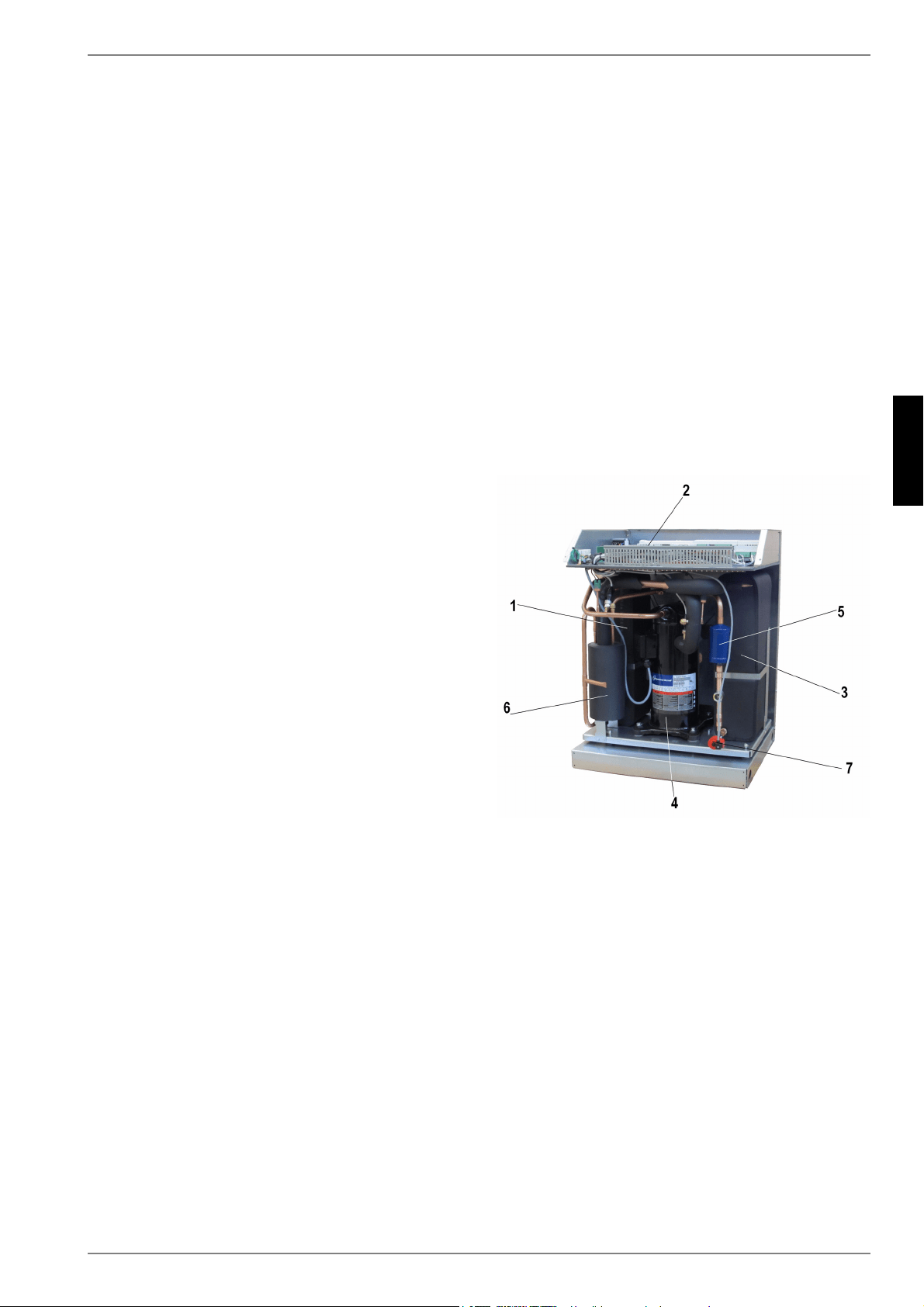
www.dimplex.de 452235.66.05 · FD 9310 FR-3
Français
SI 6TU - SI 18TU
2 Utilisation de la pompe
à chaleur
2.1 Domaine d’utilisation
La pompe à chaleur eau glycolée/eau est exclusivement prévue
pour le réchauffement de l'eau de chauffage. Elle peut être utili-
sée pour des installations de chauffages existantes ou pour des
installations nouvelles. Dans l'installation de source de chaleur,
c'est un mélange d'eau et de protection antigel (eau glycolée) qui
sert d'agent caloporteur. Des sondes géothermiques, des collec-
teurs géothermiques ou d'autres installations similaires peuvent
être utilisés comme installations de source de chaleur.
2.2 Fonctionnement
Le sol emmagasine la chaleur apportée par le soleil, le vent et la
pluie. Cette chaleur géothermique est captée par l’eau glycolée
à température basse dans le collecteur enterré, la sonde géo-
thermique ou autre. Un circulateur refoule ensuite l’eau glycolée
ainsi « chauffée » vers l’évaporateur de la pompe à chaleur dans
lequel la chaleur est délivrée au fluide frigorigène du circuit frigo-
rifique. Par cette opération, l’eau glycolée se refroidit à nouveau
de manière à pouvoir une nouvelle fois, dans le circuit d’eau gly-
colée, absorber de l’énergie thermique.
Cependant, le fluide frigorigène est aspiré par le compresseur à
commande électrique, compressé et « pompé » à un niveau de
température plus élevé. L’énergie électrique mise à disposition
tout au long de ce procédé n’est pas perdue, elle est transférée
au contraire également en grande partie au fluide frigorigène.
Le fluide frigorigène arrive alors dans le condenseur où à son
tour, il transmet l’énergie thermique à l’eau de chauffage. Ainsi,
l’eau de chauffage chauffe et atteint des températures pouvant
aller, en fonction du point de fonctionnement, jusqu’à 62 °C.
3 Appareil de base
Il s'agit d'une pompe à chaleur pour installation intérieure, prête
à brancher, avec boîtier, compartiment électrique et gestionnaire
de pompe à chaleur intégré. Le circuit réfrigérant est "herméti-
quement fermé" et contient le fluide frigorigène fluoré R410A
avec une valeur de PRG de 1975, répertorié dans le protocole de
Kyoto. Il est sans HCFC, inoffensif pour la couche d'ozone et
ininflammable.
Sur le panneau de commande figurent toutes les pièces néces-
saires à l’utilisation de la pompe à chaleur. Une sonde pour me-
surer la température du extérieur et son petit matériel de fixation
ainsi qu'un filtre sont livrés avec l'appareil. Le câble d'alimenta-
tion pour la tension de puissance et de commande doit être
posé par le client.
La ligne d'alimentation de la pompe à eau glycolée, installée par
le client, doit être raccordée au panneau de commande. À cette
occasion, prévoir une protection moteur ou un contacteur - si né-
cessaire.
La liaison de l'installation de source de chaleur au distributeur
d’eau glycolée doit être réalisée par le client.
1) Condenseur
2) Panneau de commande
3) Evaporateur
4) Compresseur
5) Sécheur de filtre
6) Economizer
7) Détendeur
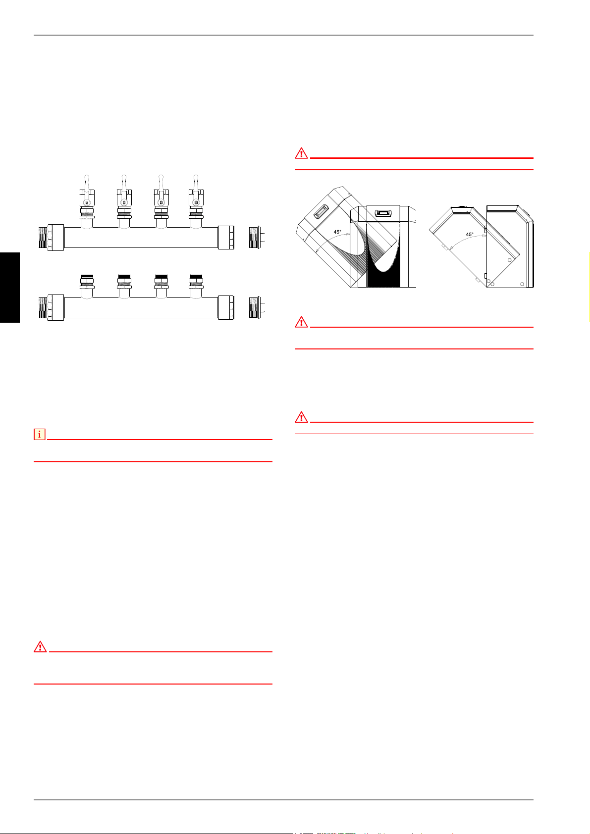
FR-4 452235.66.05 · FD 9310 www.dimplex.de
Français
SI 6TU - SI 18TU
4 Accessoires
4.1 Distributeur d'eau glycolée
Le distributeur d’eau glycolée réunit les boucles du collecteur de
l’installation de source de chaleur pour former une conduite prin-
cipale qui, elle, est raccordée à la pompe à chaleur. Les robinets
à boisseau sphérique intégrés permettent de couper chaque cir-
cuit d’eau glycolée pour permettre une purge.
4.2 Télécommande
Une station de télécommande est disponible comme accessoire
spécial pour améliorer le confort. La commande et le guidage par
menus sont identiques à ceux du gestionnaire de pompe à cha-
leur. Le raccordement s'effectue via une interface (accessoire
spécial) avec fiche Western RJ 12.
REMARQUE
Peut être utilisé directement comme station de télécommande dans le cas
de régulateurs de chauffage à unité de commande amovible.
4.3 Système de gestion technique
des bâtiments
Le gestionnaire de pompe à chaleur peut être relié au réseau
d'un système de gestion technique des bâtiments grâce à la
carte d'interface respective. Pour le raccordement précis et le
paramétrage de l'interface, respecter les instructions de mon-
tage supplémentaires de la carte d'interface.
Les liaisons réseau suivantes sont possibles pour le gestionnaire
de pompes à chaleur :
Modbus
EIB, KNX
Ethernet
ATTENTION !
En cas de commande externe de la pompe à chaleur ou des circulateurs,
prévoir un commutateur de débit servant à empêcher la mise en marche
du compresseur en cas d’absence de flux volumique.
5 Transport
Le transport par chariot élévateur convient bien à un déplace-
ment sur surface plane. Si la pompe à chaleur doit être convoyée
sur une surface non plane ou dans des escaliers, il est possible
de le faire à l'aide de sangles, que l'on peut glisser directement
sous la palette en bois.
ATTENTION !
La pompe à chaleur n’est pas fixée à la palette en bois.
ATTENTION !
Lors du transport, l’angle d’inclinaison de la pompe à chaleur ne doit pas
dépasser 45° (dans tous les sens).
Pour soulever l’appareil sans palette, veuillez utiliser les orifices
prévus dans le châssis, sur les côtés. Retirer à cet effet les pan-
neaux latéraux de l’habillage. Pour vous aider à porter l’appareil,
un tube quelconque fera l’affaire.
ATTENTION !
Ne pas soulever l’appareil en utilisant les orifices de l’habillage !
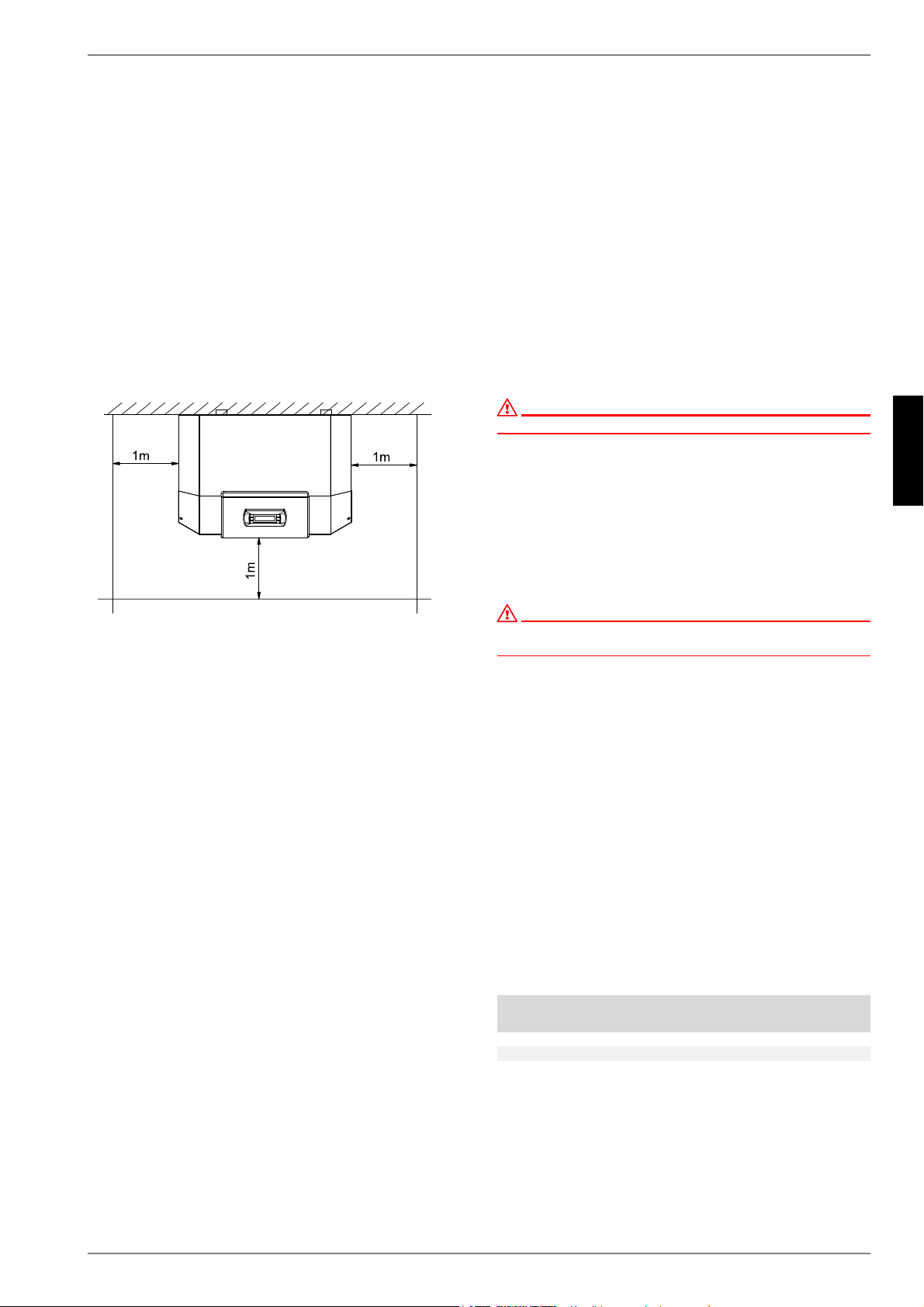
www.dimplex.de 452235.66.05 · FD 9310 FR-5
Français
SI 6TU - SI 18TU
6 Installation
6.1 Généralités
La pompe à chaleur eau glycolée/eau doit être installée dans un
local sec à l'abri du gel, sur une surface plane, lisse et horizon-
tale. Le châssis doit adhérer au sol et être étanche sur tout son
pourtour afin de garantir une insonorisation correcte. Si des
pieds sont utilisés, la pompe à chaleur doit être installée à l'hori-
zontale. Il peut se produire dans ce cas une augmentation du ni-
veau sonore indiqué pouvant aller jusqu'à 3 db(A), nécessitant
des mesures d'insonorisation supplémentaires.
La pompe à chaleur doit être mise en place de telle manière que
le service après-vente puisse y accéder sans problème, ce qui
ne fait aucun doute, si on laisse un espace d’env. 1 m devant et
sur les côtés de la pompe à chaleur.
La pièce d'installation ne doit jamais être exposée au gel ou à
des températures supérieures à 35 °C.
6.2 Emissions sonores
En raison de son isolation sonore efficace, la pompe à chaleur
est très silencieuse. La propagation du bruit sur les fondations ou
le système de chauffage est évitée dans une large mesure grâce
à des dispositifs de découplage internes.
7Montage
7.1 Remarques d’ordre général
Les raccordements suivants doivent être réalisés sur la pompe à
chaleur :
Départ et retour d'eau glycolée (installation de source de
chaleur)
Circuits départ et retour du chauffage
Sonde de température
Alimentation en tension
7.2 Branchement côté installation
de chauffage
ATTENTION !
Rincer l'installation de chauffage avant de brancher la pompe à chaleur.
Avant de procéder au raccordement de la pompe à chaleur côté
eau de chauffage, l’installation de chauffage doit être rincée pour
éliminer d’éventuelles impuretés et les restes éventuels des ma-
tériaux d’étanchéité ou autres. Une accumulation de dépôts di-
vers dans le condenseur est susceptible d'entraîner une dé-
faillance totale de la pompe à chaleur.
Une fois le montage côté chauffage terminé, l’installation de
chauffage devra être remplie, purgée et éprouvée à la pression.
ATTENTION !
La pression d'épreuve maximale s'élève côté chauffage et côté eau
glycolée à 6,0 bars (ü). Cette valeur ne doit pas être dépassée.
Respecter les consignes suivantes lors du remplissage de
l'installation :
l'eau de remplissage et l'eau additionnelle non traitées doi-
vent être de même qualité que l'eau potable
(incolore, claire et sans dépôt)
l'eau de remplissage et l'eau additionnelle doivent être pré-
filtrées
(maillage maxi. 5 µm).
Il n'est pas possible d'empêcher totalement la formation de cal-
caire dans les installations de chauffage à eau chaude. Sa quan-
tité est cependant négligeable pour les installations ayant des
températures aller inférieures à 60 °C.
Les pompes à chaleur moyenne et haute température peuvent
également atteindre des températures supérieures à 60 °C.
Les valeurs indicatives suivantes pour l'eau additionnelle et l'eau
de remplissage doivent donc être respectées selon VDI2035
feuillet 1 :
* 1 °dH = 1,7857 °f
Puissance calorifique
totale en [kW]
Somme des alcalinoter-
reux en mol/m³
ou mmol/l
Dureté
totale en °dH*
jusqu'à 200
2,0 11,2
de 200 à 600
1,5 8,4
> 600 < 0,02 < 0,11
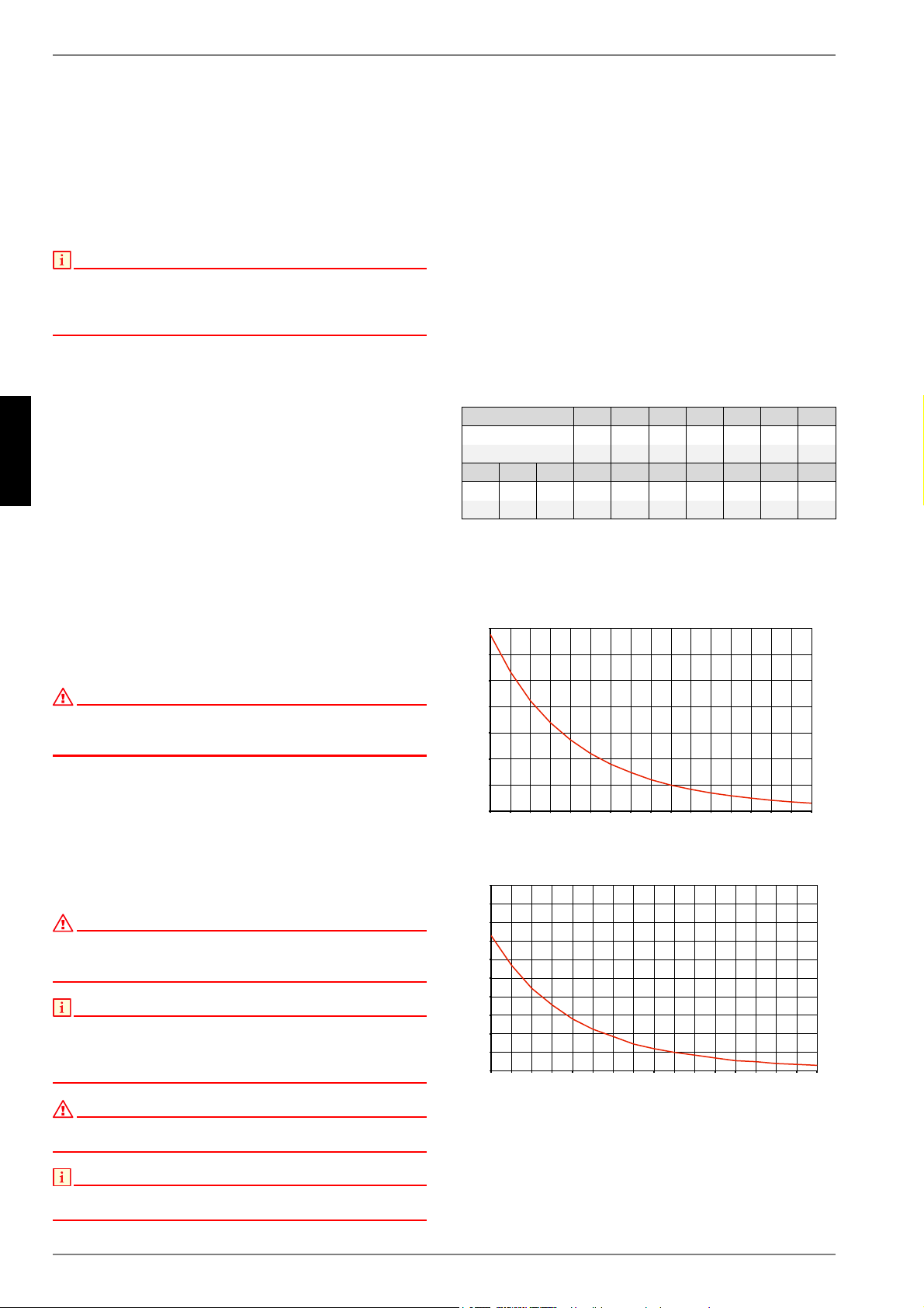
FR-6 452235.66.05 · FD 9310 www.dimplex.de
Français
SI 6TU - SI 18TU
Débit d'eau de chauffage minimum
Quel que soit l'état de fonctionnement de l'installation de chauf-
fage, un débit d'eau de chauffage minimum doit être garanti dans
la pompe à chaleur. Cela peut par ex. être obtenu par l'installa-
tion d'un distributeur double sans pression différentielle ou d'une
soupape différentielle. Vous trouverez des explications quant au
réglage d'une soupape différentielle dans le chapitre " Mise en
service
REMARQUE
L'utilisation d'une soupape différentielle est uniquement
recommandée pour les chauffages par surfaces et pour un débit
d'eau de chauffage max. de 1,3 m³/h. Le non-respect de cette remarque
peut entraîner des défauts de fonctionnement de l'installation.
La fonction de protection antigel du gestionnaire de pompe à
chaleur est activée dès que le gestionnaire de pompe à chaleur
et les circulateurs de chauffage sont prêts à fonctionner. L’instal-
lation doit être vidangée dans le cas d’une mise hors service de
la pompe à chaleur ou en cas de panne de courant. Pour les ins-
tallations de pompe à chaleur qui pourraient être victimes de
pannes de courant non décelables (maison de vacances), le cir-
cuit de chauffage doit fonctionner avec une protection anti-gel
appropriée.
7.3 Raccordement côté source de
chaleur
Pour le raccordement, il faut procéder exactement comme indi-
qué ci-après :
raccorder la conduite d’eau glycolée aux circuits départ et retour
de la pompe à chaleur. Suivre pour cela les indications du
schéma d'intégration hydraulique.
ATTENTION !
Monter, sur la pompe à chaleur, le filtre qui vous est livré dans l’ouverture
d’admission de la source de chaleur, afin de protéger l’évaporateur des
salissures.
Préparer l’eau glycolée avant de remplir l’installation. La concen-
tration de l’eau glycolée doit se monter à au moins 25 %, ce qui
garantit une protection contre le gel jusqu'à -14 °C.
Seuls, les produits antigel à base de monoéthylène-glycol ou
propylèneglycol peuvent être utilisés.
L’installation de source de chaleur doit être purgée et soumise à
des contrôles d’étanchéité.
ATTENTION !
La teneur de l’eau glycolée en produit antigel à base de monoéthylène-
glycol ou propylène-glycol, doit être d’au moins 25 % et celle-ci doit être
mélangée avant le remplissage.
REMARQUE
En cas de besoin, la plage d'utilisation peut être élargie jusqu'à une
température d'entrée de l'eau glycolée de -10 °C. Dans ce cas, la
concentration minimale en eau glycolée doit être fixée à 30 %.
(température de gel -17 °C)
ATTENTION !
La pression d'épreuve maximale s'élève côté chauffage et côté eau
glycolée à 6,0 bars (ü). Cette valeur ne doit pas être dépassée.
REMARQUE
Il appartient au client de prévoir un séparateur d’air approprié (séparateur
à microbulles d’air) dans le circuit de source de chaleur.
7.4 Sonde de température
Les sondes de températures suivantes sont déjà montées ou
doivent être installées en plus :
sonde de température extérieure (R1) fournie (NTC-2)
sonde de température retour circuit de chauffage (R2) inté-
grée (NTC-10)
sonde de température retour circuit primaire (R24) intégrée
(NTC-10)
sonde de température départ circuit de chauffage (R9) inté-
grée (NTC-10)
sonde de température départ circuit primaire (R6) intégrée
(NTC-10)
7.4.1 Courbes caractéristiques de la
sonde
Les sondes de température à raccorder au gestionnaire de
pompe à chaleur doivent être conformes aux caractéristiques de
sonde présentées à la Fig. 7.1 à la page 6. Seule exception : la
sonde de température extérieure livrée avec la pompe à chaleur
(voir Fig. 7.2 à la page 6).
Fig. 7.1:Courbe caractérisitque de la sonde NTC 10
Fig. 7.2:Courbe caractéristique de la sonde NTC-2 selon DIN 44574
Sonde de température extérieure
Température en °C -20 -15 -10 -5 0 5 10
NTC-2 en k 14,6 11,4 8,9 7,1 5,6 4,5 3,7
NTC-10 en k 67,7 53,4 42,3 33,9 27,3 22,1 18,0
15 20 25 30 35 40 45 50 55 60
2,9 2,4 2,0 1,7 1,4 1,1 1,0 0,8 0,7 0,6
14,9 12,1 10,0 8,4 7,0 5,9 5,0 4,2 3,6 3,1
7HPSpUDWXUHH[WpULHXUHHQ>&@
9DOHXUGHUpVLVWDQFHHQ>N2KP@
7HPSpUDWXUHH[WpULHXUHHQ>&@
9DOHXUGHUpVLVWDQFHHQ>N2KP@
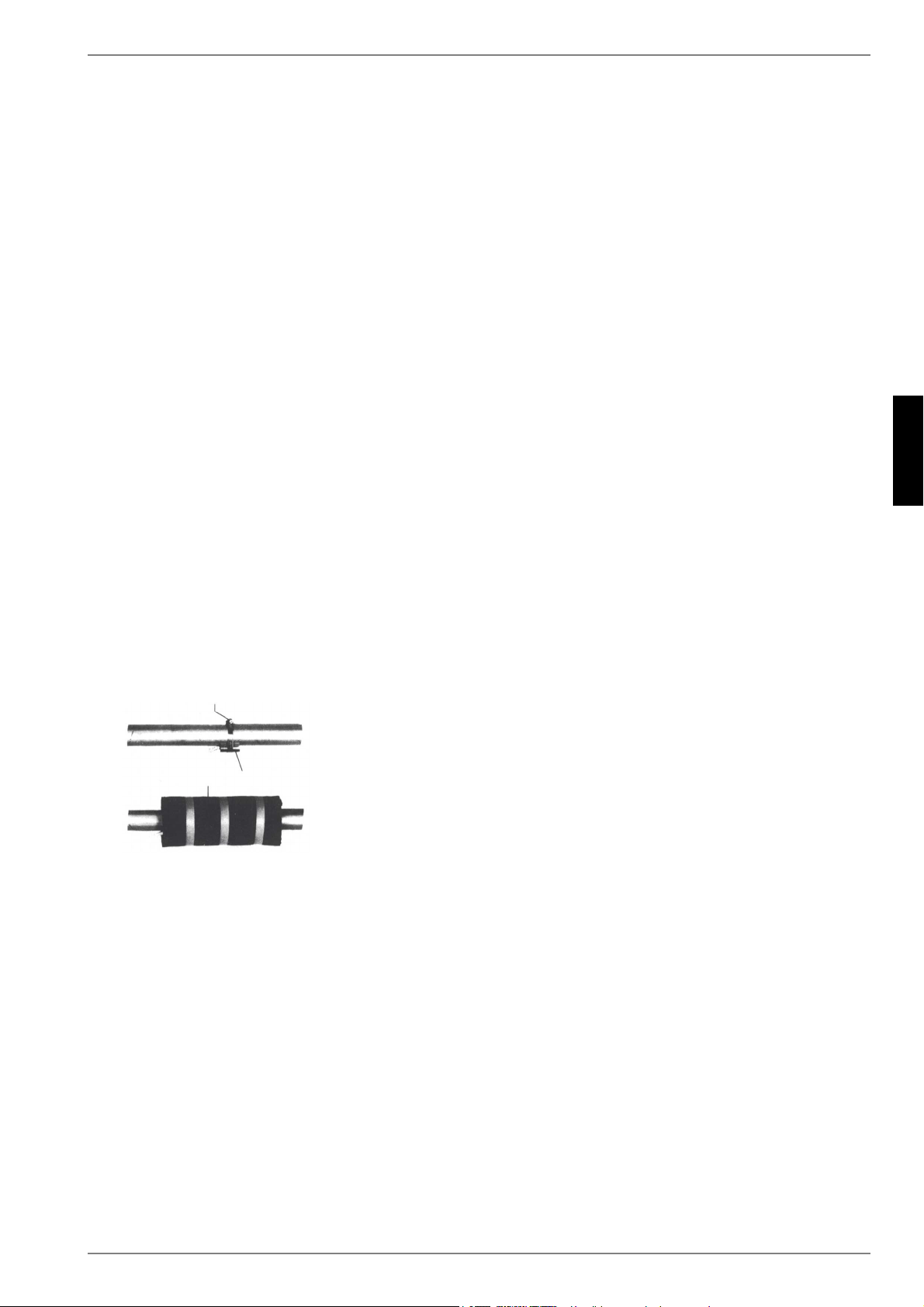
www.dimplex.de 452235.66.05 · FD 9310 FR-7
Français
SI 6TU - SI 18TU
7.4.2 Montage de la sonde de température
extérieure
La sonde de température doit être placée de telle sorte qu’elle
puisse détecter la plupart des influences atmosphériques sans
que les valeurs mesurées ne soient faussées :
sur le mur extérieur d’une pièce d’habitation chauffée, de
préférence sur la face nord ou nord-ouest,
ne pas monter dans un « emplacement protégé » (par ex.
dans la niche d’un mur ou sous le balcon),
ne pas installer à proximité de fenêtres, portes, ouvertures
d’aération, éclairage extérieur ou pompes à chaleur,
ne pas exposer aux rayons directs du soleil, quelle que soit
la saison.
Câble de sonde : longueur max. 40 m ; section de fils min.
0,75 mm² ; diamètre extérieur du câble 4 à 8 mm.
7.4.3 Montage des sondes d'applique
Le montage des sondes d'applique est nécessaire uniquement si
ces sondes sont comprises dans les fournitures de la pompe à
chaleur, mais non montées.
Les sondes d'applique peuvent être montées sur les tuyauteries
ou insérées dans le doigt de gant du distributeur compact.
Montage sur les tuyauteries
Nettoyer les tuyaux de chauffage des restes de peinture, éli-
miner la rouille et les taches d’oxydation
Enduire les surfaces nettoyées de pâte thermoconductrice
(appliquer en fine couche)
La sonde doit être fixée avec un collier pour flexibles (serrer
à fond, des sondes mal fixées engendrent des défauts) puis
isolée
7.4.4 Système de distribution hydraulique
Le distributeur compact et le distributeur double sans pression
différentielle servent d'interface entre la pompe à chaleur, le sys-
tème de distribution de chauffage, le ballon tampon et éventuel-
lement le ballon d'eau chaude sanitaire. Un système compact est
utilisé à la place de nombreux composants individuels, ce qui
simplifie l'installation. Vous trouverez des informations supplé-
mentaires dans les instructions de montage respectives.
Distributeur compact
La sonde sur circuit de retour peut être laissée dans la pompe à
chaleur ou être insérée dans le doigt de gant. L’espace entre la
sonde et le doigt de gant doit être entièrement comblé avec de la
pâte thermoconductrice.
Distributeur double sans pression différentielle
La sonde sur circuit de retour doit être installée dans le doigt de
gant du distributeur double sans pression différentielle, pour pou-
voir être traversée par le fluide des pompes du circuit de chauf-
fage des circuits générateur et consommateur.
Ballon d'eau chaude sanitaire
La sonde d'eau chaude sanitaire est fournie avec le ballon d'eau
chaude sanitaire et est montée dans la gaine correspondante.
7.5 Branchements électriques
7.5.1 Généralités
Tous les branchements électriques doivent être effectués exclu-
sivement par un électricien ou un professionnel formé aux tâches
définies et dans le respect
des instructions de montage et d'utilisation,
des prescriptions d'installation nationales, par ex.
VDE 0100,
des conditions techniques de branchement de l'exploitant
de l'entreprise publique d'électricité et du réseau d'alimenta-
tion (par ex. TAB) et
des conditions locales
Pour garantir la fonction de protection antigel de la pompe à cha-
leur, le gestionnaire de pompe à chaleur ne doit pas être hors
tension et la pompe à chaleur doit toujours être traversée par un
fluide.
Les contacts des relais de sortie sont déparasités. C'est pour-
quoi, en fonction de la résistance interne d'un appareil de me-
sure et même dans le cas de contacts non fermés, une tension
bien inférieure à la tension secteur est mesurée.
Une faible tension est appliquée aux bornes N1-J1 à N1-J11 ;
N1-J19 ; N1-J20 ; N1-J23 à N1-J26 du régulateur ainsi qu'au bor-
nier X3; X5.1. Une tension secteur appliquée à ces bornes par
suite d'une erreur de câblage détruit le gestionnaire de pompe à
chaleur.
&ROOLHU
6RQGHGDSSOLTXH
,VRODWLRQWKHUPLTXH

FR-8 452235.66.05 · FD 9310 www.dimplex.de
Français
SI 6TU - SI 18TU
7.5.2 Branchements électriques
1) La ligne d’alimentation à 4 fils électriques de la partie puis-
sance de la pompe à chaleur est amenée du compteur de
courant de la PAC via le contacteur de blocage de la société
d’électricité (si existant) à la pompe à chaleur Branchement
de la ligne de charge sur le panneau de commande de la
pompe à chaleur par la borne X1 : L1/L2/L3/ PE.
Sur l’alimentation de puissance de la pompe à chaleur, pré-
voir une coupure omnipolaire avec au moins 3 mm d'écarte-
ment d'ouverture de contact (p. ex. contacteur de blocage
de la société d'électricité ou contacteur de puissance) ainsi
qu'un coupe-circuit automatique omnipolaire, avec déclen-
chement simultané de tous les conducteurs extérieurs (cou-
rant de déclenchement suivant spécifications techniques).
ATTENTION !
Garantir la rotation à droite du champ magnétique : si le câblage est mal
effectué, la pompe à chaleur ne peut pas fonctionner. Un avertissement
correspondant s’affiche sur le gestionnaire de pompe à chaleur (changer
le câblage)
2) La ligne d’alimentation à 3 fils électriques du gestionnaire de
pompe à chaleur (régulateur de chauffage N1) est amenée
à la pompe à chaleur . Branchement de la ligne de com-
mande sur le panneau de commande de la pompe à chaleur
par la borne X2 : L/N/PE.
Vous trouverez les données sur la puissance absorbée par
la pompe à chaleur dans les informations produits ou sur la
plaque signalétique.
La ligne d’alimentation (L/N/PE~230 V, 50 Hz) du gestion-
naire WPM doit être sous tension permanente. Elle est, de
ce fait, à saisir avant le contacteur de blocage de la société
d’électricité ou à relier au courant domestique. Certaines
fonctions de protection essentielles seraient sinon hors ser-
vice lors des durées de blocage.
3) Le contacteur de blocage de la société d’électricité (K22)
avec 3 contacts principaux (1/3/5 // 2/4/6) et un contact auxi-
liaire (contact NO 13/14) doit être dimensionné en fonction
de la puissance de la pompe à chaleur et fourni par le client.
Le contact normalement ouvert du contacteur de blocage de
la société d’électricité (13/14) est bouclé entre le bornier X3/
G et la borne de connecteur X3/A1. ATTENTION ! Faible
tension !
4) Le contacteur (K20) de la résistance immergée (E10) doit
être dimensionné, sur les installations mono-énergétiques
(2ème générateur de chaleur) en fonction de la puissance
de la résistance et fourni par le client. La commande
(230 V AC) s’effectue à partir du gestionnaire de pompe à
chaleur via les bornes de connexion X2/N et X2/K20.
5) Le contacteur (K21) de la cartouche chauffante (E9) dans le
ballon d'eau chaude sanitaire doit être dimensionné en fonc-
tion de la puissance de la cartouche et fourni par le client. La
commande (230 V AC) s’effectue à partir du gestionnaire de
pompe à chaleur via les bornes X2/N et X2/K21.
6) Les contacteurs décrits aux points 3, 4 et 5 sont montés
dans la distribution électrique. La ligne de puissance de la
résistance électrique intégrée doit être posée et sécurisée
conformément aux normes et prescriptions en vigueur.
7) Tous les fils électriques installés nécessitent un câblage
permanent et fixe.
8) Le circulateur du circuit de chauffage (M13) est branché aux
bornes X2/N et X2/M13.
9) La pompe de charge eau chaude sanitaire (M18) est bran-
chée aux bornes X2/N et X2/M18.
10) La pompe de puits ou d’eau glycolée (M11) est branchée
aux bornes X2/N et X2/M11 et PE.
11) Pour les pompes à chaleur, la sonde sur circuit de retour
est intégrée et amenée au gestionnaire de pompe à cha-
leur via la ligne de commande. La sonde sur circuit de retour
doit être installée dans le doigt de gant du distributeur uni-
quement en cas d'utilisation d'un distributeur double sans
pression différentielle. Puis les conducteurs doivent être
fixés aux bornes X3/GND et X3/R2.1. Le pont A-R2 situé à
la livraison entre X3/B2 et X3/1 doit ensuite être déplacé sur
les bornes X3/1 et X3/2.
12) La sonde extérieure (R1) est reliée aux bornes X3/GND et
X3/R1.
13) La sonde d'eau chaude sanitaire (R3) est fournie avec le
ballon d'eau chaude sanitaire et reliée aux bornes X3/GND
et X3/R3.
7.5.3 Branchement du circulateur à
régulation électronique
Les circulateurs à régulation électronique se caractérisent par
des courants de démarrage élevés qui peuvent être préjudicia-
bles à la longévité du gestionnaire de pompe à chaleur selon les
circonstances. C'est la raison pour laquelle un relais de couplage
est installé/doit être installé entre la sortie du gestionnaire de
pompe à chaleur et le circulateur à régulation électronique. Cette
disposition n'est pas nécessaire si le circulateur à régulation
électronique ne dépasse pas les seuils admissibles (courant de
service de 2 A et courant de démarrage maximal de 12 A) ou si
l'absence de relais est expressément autorisée par le fabricant
de la pompe.
ATTENTION !
Il est interdit de connecter plus d'un circulateur à régulation électronique
via une sortie de relais.
8 Mise en service
8.1 Généralités
Pour garantir une mise en service en règle, cette dernière doit
être effectuée par un service après-vente agréé par le construc-
teur. Une garantie supplémentaire est ainsi associée sous certai-
nes conditions (voir garantie).
8.2 Préparation
Avant la mise en service, il est impératif de procéder aux vérifica-
tions suivantes :
tous les raccordements de la pompe à chaleur doivent être
réalisés comme décrit au chapitre 7.
l'installation de source de chaleur et le circuit de chauffage
doivent être remplis et testés.
le filtre doit se trouver dans l'ouverture d'admission d'eau
glycolée de la pompe à chaleur.
dans les circuits de chauffage et d'eau glycolée, toutes les
vannes susceptibles de perturber l'écoulement doivent être
ouvertes.
Le gestionnaire de pompe à chaleur doit être raccordé à
l'installation de chauffage conformément à ses instructions
de service.
www.dimplex.de 452235.66.05 · FD 9310 FR-9
Français
SI 6TU - SI 18TU
8.3 Procédures à suivre lors de la
mise en service
La mise en service de la pompe à chaleur s’effectue via le ges-
tionnaire de pompe à chaleur.
ATTENTION !
La mise en service de la pompe à chaleur doit s’effectuer conformément
aux instructions de montage et d’utilisation du gestionnaire de pompe à
chaleur.
Si le débit minimal en eau de chauffage est assuré par une sou-
pape différentielle, il faut l'adapter à l'installation de chauffage.
Un mauvais réglage pourrait conduire à divers messages d’er-
reur et à une augmentation du besoin en énergie électrique. Pour
régler la soupape de trop-plein correctement, nous vous con-
seillons de procéder de la manière suivante.
Fermez tous les circuits de chauffage pouvant l'être en phase de
fonctionnement, selon l'utilisation qu'il en est faite ; ceci ayant
pour but d'obtenir le débit d'eau le plus défavorable. En règle gé-
nérale, ce sont les circuits de chauffage des locaux donnant sur
le côté sud et ouest. Au moins un des circuits de chauffage doit
rester ouvert (par ex. salle de bains).
La soupape différentielle est à ouvrir au maximum de telle sorte
que, pour la température actuelle des sources d’énergie, l'étale-
ment maximal de température, indiqué dans le tableau, entre cir-
cuit départ et retour du chauffage, soit obtenu. Il faut mesurer
l'étalement de température le plus proche possible de la pompe
à chaleur. Dans des installations mono-énergétiques, désactiver
la cartouche chauffante pendant la mise en service
9 Entretien / nettoyage
9.1 Entretien
Pour éviter des dysfonctionnements dus à des dépôts dans les
échangeurs thermiques de la pompe à chaleur, il faut veiller à ce
qu'aucune sorte de dépôt ne puisse s'introduire dans les installa-
tions de chauffage et de source de chaleur. Si des dysfonction-
nements dus à des impuretés devaient quand même se produire,
l’installation devra être nettoyée comme indiqué ci-après.
9.2 Nettoyage côté chauffage
L’oxygène est susceptible d’entraîner la formation de produits
d’oxydation (rouille) dans l’eau de chauffage, notamment lorsque
des composants en acier sont utilisés. Celui-ci gagne le système
de chauffage par les vannes, les circulateurs ou les tuyaux en
matière plastique. C’est pourquoi il faut veiller à ce que l’installa-
tion reste étanche à la diffusion, notamment en ce qui concerne
les tuyaux du chauffage au sol.
REMARQUE
Il est recommandé de faire appel à un système approprié de protection
contre la corrosion pour éviter les dépôts (rouille par ex.) dans le
condensateur de la pompe à chaleur.
Il est également possible que l’eau de chauffage soit souillée par
des restes de graisse et d’agents d’étanchéification.
Si en raison d’impuretés la puissance du condenseur de la
pompe à chaleur se trouve réduite, l’installation devra être net-
toyée par l’installateur.
Dans l'état actuel des connaissances, nous conseillons de pro-
céder au nettoyage avec de l'acide phosphorique à 5 % ou, si le
nettoyage doit avoir lieu plus souvent, avec de l'acide formique à
5%.
Dans les deux cas, le liquide de nettoyage doit être à la tempéra-
ture ambiante. Il est recommandé de nettoyer l'échangeur de
chaleur dans le sens contraire au sens normal du débit.
Pour éviter l’infiltration de nettoyant contenant de l’acide dans le
circuit de l’installation de chauffage, nous vous recommandons
de raccorder l’appareil de nettoyage directement sur le départ et
le retour du condenseur. Il faut ensuite soigneusement rincer à
l’aide de produits neutralisants adéquats, afin d’éviter tous dom-
mages provoqués par d’éventuels restes de produits de net-
toyage dans le système.
Les acides doivent être utilisés avec précaution et les prescrip-
tions des caisses de prévoyance des accidents doivent être res-
pectées.
Observer systématiquement les consignes du fabricant de déter-
gent.
Température
source de chaleur
Différence de température max.
entre circuits départ et retour du
chauffage
de à
-5 °C 0 °C 10 K
1 °C 5 °C 11 K
6 °C 9 °C 12 K
10 °C 14 °C 13 K
15 °C 20 °C 14 K
21 °C 25 °C 15 K

FR-10 452235.66.05 · FD 9310 www.dimplex.de
Français
SI 6TU - SI 18TU
9.3 Nettoyage côté source de
chaleur
ATTENTION !
Monter, sur la pompe à chaleur, le filtre qui vous est livré dans l’ouverture
d’admission de la source de chaleur, afin de protéger l’évaporateur des
salissures.
Il est recommandé de nettoyer le filtre du filtre un jour après la
mise en service. Définir la périodicité des contrôles suivants en
fonction de l'encrassement. Si aucune souilluren’est plus à si-
gnaler, on pourra démonter le tamis du filtre et réduire ainsi les
pertes de pression
10 Défaillances / recherche
de pannes
Cette pompe à chaleur est un produit de qualité. Si un dysfonc-
tionnement devait quand même survenir, celui-ci sera affiché sur
l'écran du gestionnaire de pompe à chaleur. Référez-vous pour
cela à la page des dysfonctionnements et de recherche de
panne dans les instructions du gestionnaire de pompe à chaleur.
Si vous n'êtes pas en mesure de remédier vous-même au dys-
fonctionnement, veuillez vous adresser au service après-vente
compétent.
ATTENTION !
Les travaux sur la pompe à chaleur doivent être effectués uniquement par
des techniciens qualifiés et agréés.
ATTENTION !
Avant d’ouvrir l’appareil, assurez-vous que tous les circuits électriques
sont bien hors tension.
11 Mise hors service / mise
au rebut
Avant de démonter la pompe à chaleur, il faut mettre la machine
hors tension et fermer toutes les vannes. Le démontage de la
pompe à chaleur doit être exécuté par du personnel spécialisé. Il
faut se conformer aux exigences relatives à l'environnement
quant à la récupération, la réutilisation et l’élimination de con-
sommables et de composants en accord avec les normes en vi-
gueur. Une attention toute particulière doit être prêtée à l’évacua-
tion du réfrigérant et de l’huile de la machine frigorifique, qui doit
s’effectuer selon les règles de l’art.
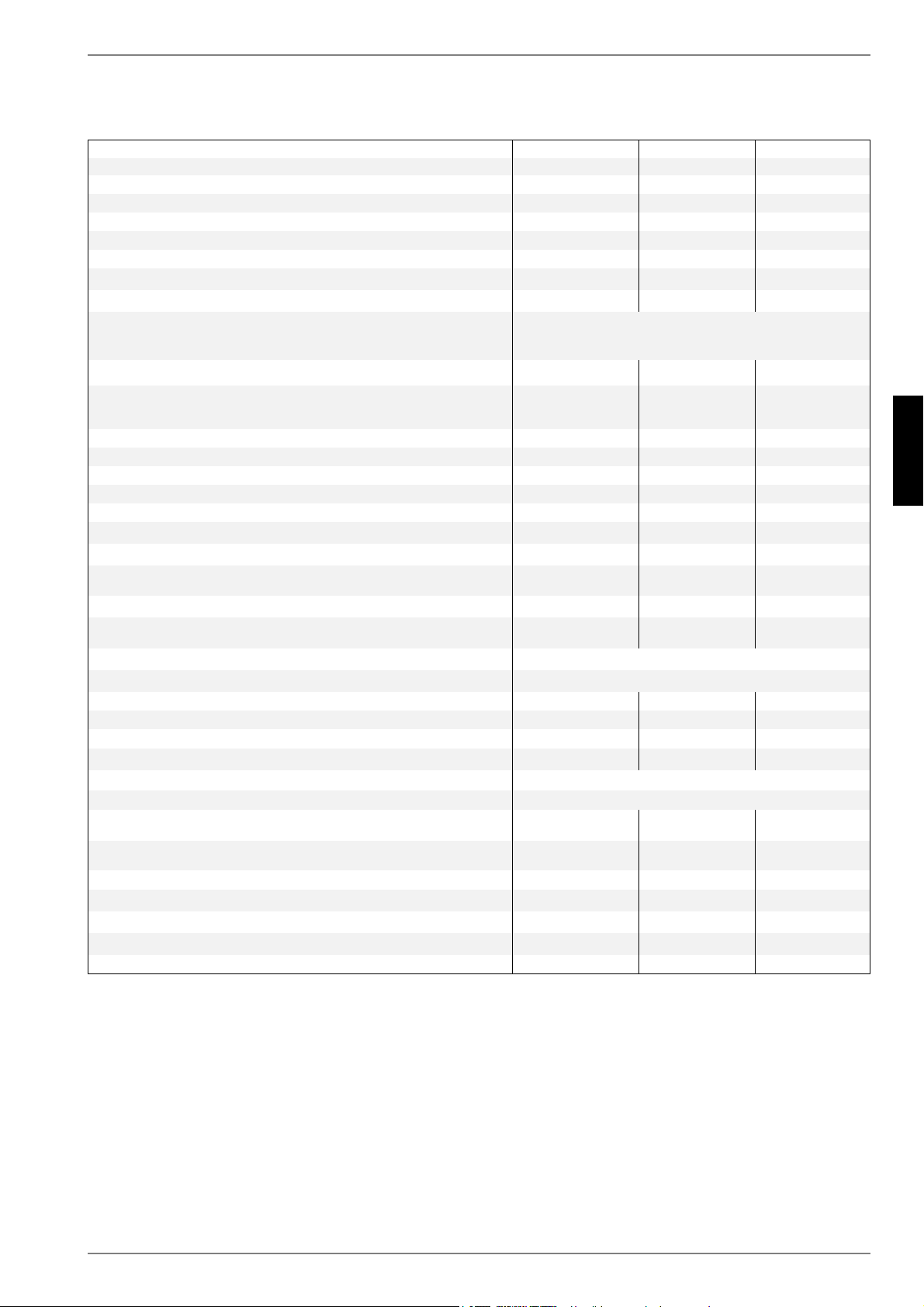
www.dimplex.de 452235.66.05 · FD 9310 FR-11
Français
SI 6TU - SI 18TU
12 Informations sur les appareils
1 Désignation technique et commerciale
SI 6TU SI 8TU SI 11TU
2Forme
2.1 Version Universelle Universelle Universelle
2.2 Régulateur interne interne interne
2.3 Calorimètre intégré intégré intégré
2.4 Emplacement / degré de protection selon EN 60 529 en intérieur/ IP 21 en intérieur/ IP 21 en intérieur / IP 21
2.5 Niveaux de puissance 111
3 Plages d'utilisation
3.1 Circuit de départ de l'eau de chauffage
1
°C
1. En cas de besoin, la plage d'exploitation peut être élargie jusqu'à une température d'entrée de l'eau glycolée de -10 °C. Dans ce cas, la concentration minimale en eau glycolée
doit être fixée à 30 %. (température de gel -17 °C). À une température de l'eau glycolée comprise entre -10 °C et -5 °C, température départ croissante de 55 °C à 62 °C.
20 à 62 ±2 20 à 62 ±2 20 à 62 ±2
3.2 Eau glycolée (source de chaleur) °C
Produit antigel
Concentration minimale en eau glycolée (température de gel -13 °C)
1
de -5
1
à +25
2
monoéthylène glycol
25 %
1
2. Exploitation possible jusqu'à une température d'entrée de l'eau glycolée de +35 °C. À une température de l'eau glycolée comprise entre +25 °C et +35 °C, température départ
décroissante de 62 °C à 55 °C.
4 Puissance / débit
3
3. Ces indications caractérisent la taille et le rendement de l'installation selon EN 14511. Le point de bivalence et la régulation sont à prendre en compte pour des considérations
économiques et énergétiques. Ici, B0W55 signifie par ex. : température de la source de chaleur 0 °C et température départ de l'eau de chauffage 55 °C. Ces données sont uni-
quement atteintes avec des échangeurs thermiques propres. Des remarques sur l'entretien, la mise en service et le fonctionnement sont mentionnées aux paragraphes corres-
pondants des instructions de montage et d'utilisation.
4.1 Débit d’eau de chauffage en cas de différence de pression interne
max:
(EN14511) m³/h / Pa
min: m³/h / Pa
1,05 / 5300
0,55 / 1500
1,4 / 7700
0,7 / 1900
1,9 / 10500
0,9 / 2400
4.2 Capacité thermique / coefficient de performance EN 14511 EN 14511 EN 14511
pour B-5 / W45 kW / --- 5,0 / 3,1 6,5 / 3,2 9,1 / 3,2
pour B0 / W55 kW / --- 5,5 / 2,8 7,2 / 2,8 10,0 / 2,9
pour B0 / W45 kW / --- 5,8 / 3,6 7,5 / 3,6 10,4 / 3,7
pour B0 / W35 kW / --- 6,1 / 4,7 8,1 / 4,8 10,9 / 4,9
4.3 Niveau de puissance sonore selon EN 12102
4
dB(A)
4. Les valeurs sonores indiquées sont uniquement valables en cas d'exploitation sans pieds. En cas d'utilisation des pieds, le niveau sonore peut augmenter de 3db (A) max.
46 46 47
4.4 Niveau de pression acoustique à 1 m de distance
4
5
dB(A)
5. Le niveau de pression sonore indiqué correspond au bruit de fonctionnement de la pompe à chaleur en mode chauffage à une température aller de 35 °C. Le niveau de puissance
sonore indiqué est celui d’une propagation de champ libre. Selon le lieu d'installation, la valeur mesurée peut varier de 16 db(A) max.
34 34 35
4.5 Débit d'eau glycolée avec difféence de pression interne
source de chaleur m³/h / Pa
1,45 / 8700 1,9 / 11000 2,6 / 14000
5 Dimensions / raccordements et poids
5.1 Dimensions de l’appareil sans raccordements pieds sont
6
H x l x L cm
6. Tenir compte de la place nécessaire plus importante pour le raccordement des tuyaux, la commande et l’entretien.
845 x 650 x 565 845 x 650 x 565 845 x 650 x 565
5.2 Raccordements de l’appareil de chauffage pouces
Filetage ext. 1 1/4"
7
7. à joint plat
5.3 Raccordements de l’appareil à la source de chaleur pouces
Filetage ext. 1 1/4"
7
5.4 Poids de/des unités de transport, emballage compris kg 119 128 134
5.5 Fluide frigorigène / poids total au remplissage type / kg R410A / 2,5 R410A / 2,9 R410A / 3,3
5.6 Lubrifiant / capacité totale type / litres Polyolester (POE)/ 0,7 Polyolester (POE)/ 1,2 Polyolester (POE)/1,2
6 Branchements électriques
6.1 Tension de charge / protection par fusibles V / A 3~ / PE 400V (50Hz) / C10A
6.2 Tension de commande / protection par fusibles V / A 1~ / N / PE 230V (50Hz) / C13A
6.3 Puissance nominale absorbée
B0 / W35 / absorption max.
3
kW
1,30 / 2,6 1,67 / 3,2 2,22 / 4,3
6.4 Courant de démarrage avec démarreur progressif A
28
(sans démarrage progressif)
17 20
6.5 Courant nominal B0 / W35 / cos A / --- 2,35 / 0,8 3,01 / 0,8 4,01 / 0,8
7 Conforme aux dispositions de sécurité européennes
8
8. Voir déclaration de conformité CE
8 8
8 Autres caractéristiques techniques
8.1 Eau de chauffage dans l’appareil protégée du gel
9
9. Le circulateur du circuit de chauffage et le gestionnaire de la pompe à chaleur doivent toujours être prêts à fonctionner.
oui oui oui
8.2 Surpression de service max.
(source de chaleur/dissipation thermique) bar 3,0 3,0 3,0
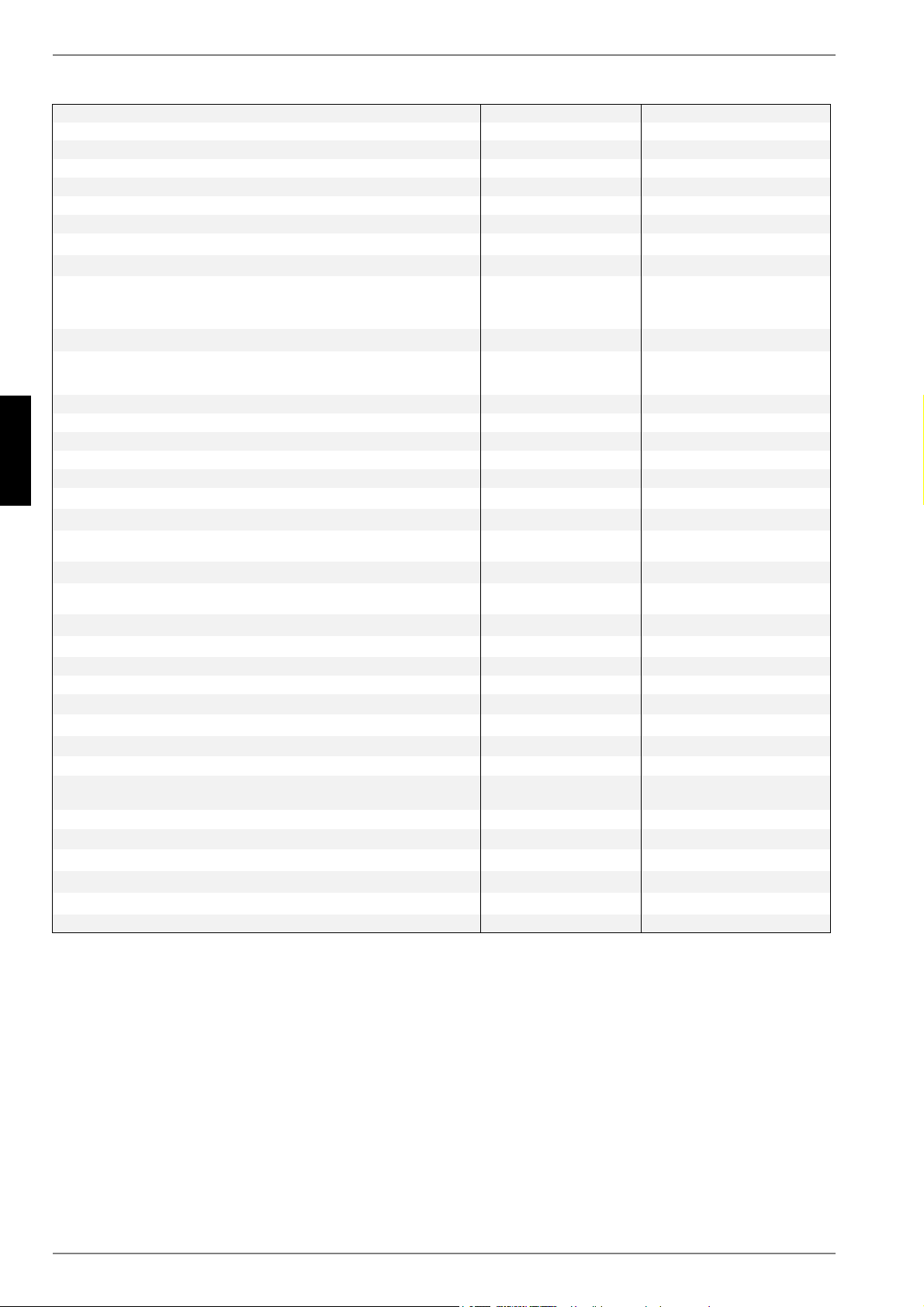
FR-12 452235.66.05 · FD 9310 www.dimplex.de
Français
SI 6TU - SI 18TU
1 Désignation technique et commerciale
SI 14TU SI 18TU
2Forme
2.1 Version Universelle Universelle
2.2 Régulateur interne interne
2.3 Calorimètre intégré intégré
2.4 Emplacement / degré de protection selon EN 60 529 en intérieur / IP 21 en intérieur / IP 21
2.5 Niveaux de puissance 1 1
3 Plages d'utilisation
3.1 Circuit de départ de l'eau de chauffage
1
°C
1. En cas de besoin, la plage d'exploitation peut être élargie jusqu'à une température d'entrée de l'eau glycolée de -10 °C. Dans ce cas, la concentration minimale en eau glycolée
doit être fixée à 30 %. (température de gel -17 °C). À une température de l'eau glycolée comprise entre -10 °C et -5 °C, température départ croissante de 55 °C à 62 °C.
20 à 62 ±2 20 bis 62 ±2
3.2 Eau glycolée (source de chaleur) °C
Produit antigel
Concentration minimale en eau glycolée (température de gel -13 °C)
1
de -5
1
à +25
2
monoéthylène glycol
25 %
1
2. Exploitation possible jusqu'à une température d'entrée de l'eau glycolée de +35 °C. À une température de l'eau glycolée comprise entre +25 °C et +35 °C, température départ
décroissante de 62 °C à 55 °C.
de -5
1
à +25
2
monoéthylène glycol
25 %
1
4 Puissance / débit
3
3. Ces indications caractérisent la taille et le rendement de l'installation selon EN 14511. Le point de bivalence et la régulation sont à prendre en compte pour des considérations
économiques et énergétiques. Ici, B0W55 signifie par ex. : température de la source de chaleur 0 °C et température départ de l'eau de chauffage 55 °C. Ces données sont uni-
quement atteintes avec des échangeurs thermiques propres. Des remarques sur l'entretien, la mise en service et le fonctionnement sont mentionnées aux paragraphes corres-
pondants des instructions de montage et d'utilisation.
4.1 Débit d’eau de chauffage en cas de différence de pression interne
max:
(EN14511) m³/h / Pa
min: m³/h / Pa
2,4 / 10700
1,2 / 2700
3,0 / 18000
1,5 / 4500
4.2 Capacité thermique / coefficient de performance EN 14511 EN 14511
pour B-5 / W45 kW / --- 11,6 / 3,3 14,9 / 3,2
pour B0 / W55 kW / --- 12,8 / 3,0 16,5 / 2,9
pour B0 / W45 kW / --- 13,3 / 3,8 17,0 / 3,6
pour B0 / W35 kW / --- 13,9 / 5,0 17,5 / 4,7
4.3 Niveau de puissance sonore selon EN 12102
4
dB(A)
4. Les valeurs sonores indiquées sont uniquement valables en cas d'exploitation sans pieds. En cas d'utilisation des pieds, le niveau sonore peut augmenter de 3db (A) max.
47 50
4.4 Niveau de pression acoustique à 1 m de distance
4
5
dB(A)
5. Le niveau de pression sonore indiqué correspond au bruit de fonctionnement de la pompe à chaleur en mode chauffage à une température aller de 35 °C. Le niveau de puissance
sonore indiqué est celui d’une propagation de champ libre. Selon le lieu d'installation, la valeur mesurée peut varier de 16 db(A) max.
35 38
4.5 Débit d'eau glycolée avec difféence de pression interne
source de chaleur m³/h / Pa
3,4 / 14000 4,3 / 21500
5 Dimensions / raccordements et poids
5.1 Dimensions de l’appareil sans raccordements pieds sont
6
H x l x L cm
6. Tenir compte de la place nécessaire plus importante pour le raccordement des tuyaux, la commande et l’entretien.
845 x 650 x 565 845 x 650 x 665
5.2 Raccordements de l’appareil de chauffage pouces
Filetage ext. 1 1/4"
7
7. à joint plat
Filetage ext. 1 1/4“ AG
7
5.3 Raccordements de l’appareil à la source de chaleur pouces
Filetage ext. 1 1/4"
7
Filetage ext. 1 1/2“ AG
7
5.4 Poids de/des unités de transport, emballage compris kg 140 163
5.5 Fluide frigorigène / poids total au remplissage type / kg R410A / 4,4 R410A / 5,2
5.6 Lubrifiant / capacité totale type / litres Polyolester (POE) / 1,2 Polyolester (POE)/ 1,9
6 Branchements électriques
6.1 Tension de charge / protection par fusibles V / A 3~ / PE 400V (50Hz) / C13A 3~ / PE 400V (50Hz) / C16A
6.2 Tension de commande / protection par fusibles V / A 1~ / N / PE 230V (50Hz) / C13A 1~ / N / PE 230V (50Hz) / C13A
6.3 Puissance nominale absorbée
B0 / W35 / absorption max.
3
kW
2,78 / 5,4 3,72 / 7,2
6.4 Courant de démarrage avec démarreur progressif A 23 28
6.5 Courant nominal B0 / W35 / cos A / --- 5,02 / 0,8 6,71 / 0,8
7 Conforme aux dispositions de sécurité européennes
8
8. Voir déclaration de conformité CE
8
8 Autres caractéristiques techniques
8.1 Eau de chauffage dans l’appareil protégée du gel
9
9. Le circulateur du circuit de chauffage et le gestionnaire de la pompe à chaleur doivent toujours être prêts à fonctionner.
oui oui
8.2 Surpression de service max. (source de chaleur/dissipation thermique) bar 3,0 3,0

www.dimplex.de 452235.66.05 · FD 9310 A-I
Anhang · Appendix · Annexes
SI 6TU - SI 18TU
Anhang / Appendix / Annexes
1 Maßbilder / Dimension Drawings / Schémas cotés................................................................... A-II
1.1 Maßbild / Dimension Drawing / Schéma coté SI 6TU - SI 14TU ............................................................ A-II
1.2 Maßbild / Dimension Drawing / Schéma coté SI 18TU..........................................................................A-III
2 Diagramme / Diagrams / Diagrammes....................................................................................... A-IV
2.1 Kennlinien / Characteristic Curves / Courbes caractéristiques SI 6TU.................................................A-IV
2.2 Kennlinien / Characteristic Curves / Courbes caractéristiques SI 8TU..................................................A-V
2.3 Kennlinien / Characteristic Curves / Courbes caractéristiques SI 11TU...............................................A-VI
2.4 Kennlinien / Characteristic Curves / Courbes caractéristiques SI 14TU..............................................A-VII
2.5 Kennlinien / Characteristic Curves / Courbes caractéristiques SI 18TU.............................................A-VIII
2.6 Einsatzgrenzendiagramm / Operating limits diagram /
Diagramme des seuils d'utilisation SI 6TU - SI 18TU............................................................................A-IX
3 Stromlaufpläne / Circuit Diagrams / Schémas électriques....................................................... A-X
3.1 Steuerung / Control / Commande ...........................................................................................................A-X
3.2 Steuerung / Control / Commande ..........................................................................................................A-XI
3.3 Last / Load / Charge .............................................................................................................................A-XII
3.4 Anschlussplan / Connection Plan / Schéma de connexion.................................................................A-XIII
3.5 Anschlussplan / Connection Plan / Schéma de connexion................................................................ A-XIV
3.6 Legende / Legend / Légende............................................................................................................... A-XV
4 Hydraulisches Einbindungsschema / Hydraulic integration diagram /
Schéma d'intégration hydraulique..........................................................................................A-XVII
4.1 Monovalente Wärmepumpenanlage mit einem Heizkreis und Warmwasserbereitung / Monovalent heat
pump system with one heating circuits and domestic hot water preparation / Installation monovalente de
pompe à chaleur avec une circuits de chauffage et production d'eau chaude sanitaire................... A-XVII
4.2 Legende / Legend / Légende............................................................................................................ A-XVIII
5 Konformitätserklärung / Declaration of Conformity / Déclaration de conformité ...............A-XIX
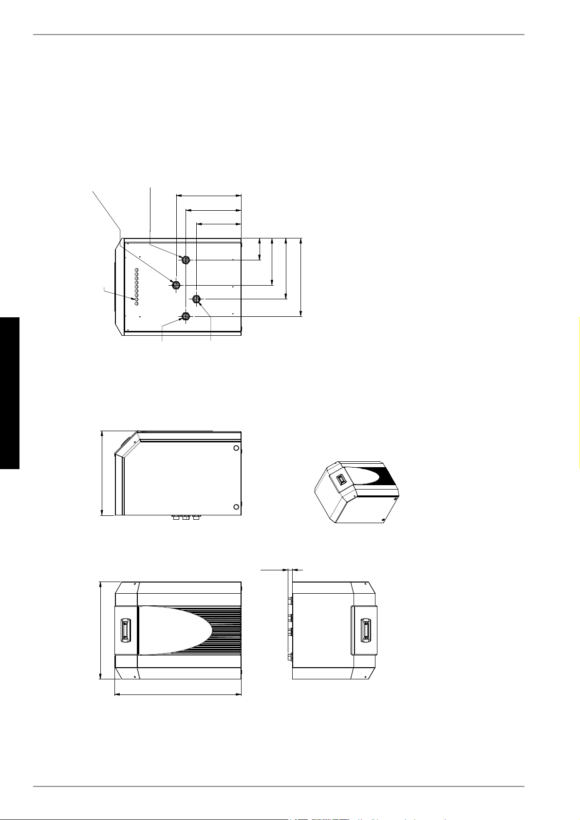
A-II 452235.66.05 · FD 9310
Anhang · Appendix · Annexes
SI 6TU - SI 18TU
1 Maßbilder / Dimension Drawings / Schémas cotés
1.1 Maßbild / Dimension Drawing / Schéma coté SI 6TU - SI 14TU
F
D
=XIKUXQJ(OHNWUROHLWXQJHQ
6XSSO\FDEOHV
$PHQpHOLJQHVpOHFWULTXHV
+HL]XQJVYRUODXI
$XVJDQJDXV:3
´$XHQJHZLQGH
+HDWLQJZDWHUIORZ
+HDWSXPSRXWOHW
´H[WHUQDOWKUHDG
$OOHUHDXGHFKDXIIDJH
6RUWLHGHOD3$&
)LOHWDJHH[WpULHXU´
+HL]XQJVUFNODXI
(LQJDQJLQ:3
´$XHQJHZLQGH
+HDWLQJZDWHUUHWXUQIORZ
+HDWSXPSLQOHW
´H[WHUQDOWKUHDG
5HWRXUHDXGHFKDXIIDJH
(QWUpHGDQVOD3$&
)LOHWDJHH[WpULHXU´
:lUPHTXHOOH
(LQJDQJLQ:3
´$XHQJHZLQGH
+HDWVRXUFH
+HDWSXPSLQOHW
´H[WHUQDOWKUHDG
6RXUFHGHFKDOHXU
(QWUpHGDQVOD3$&
)LOHWDJHH[WpULHXU´
:lUPHTXHOOH
$XVJDQJDXV:3
´$XHQJHZLQGH
+HDWVRXUFH
+HDWSXPSRXWOHW
´H[WHUQDOWKUHDG
6RXUFHGHFKDOHXU
6RUWLHGHOD3$&
)LOHWDJHH[WpULHXU´
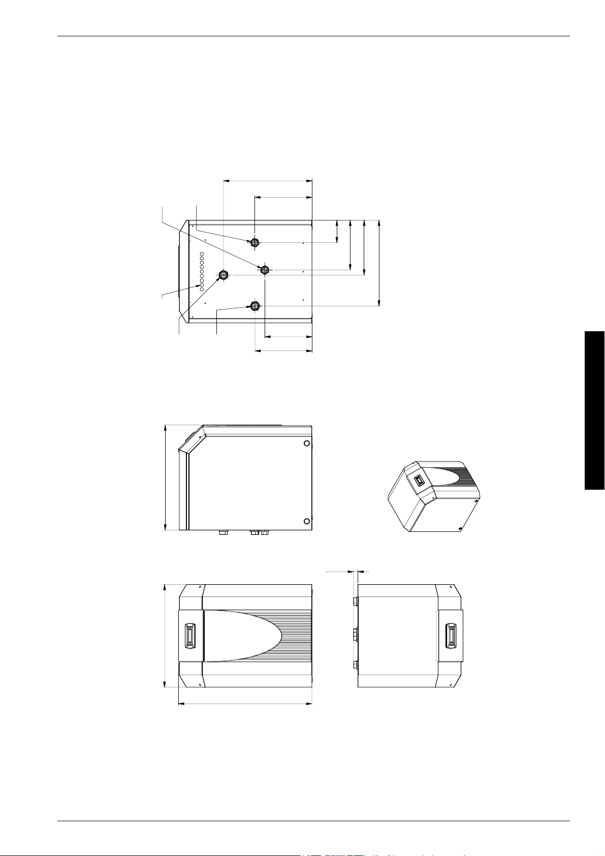
www.dimplex.de 452235.66.05 · FD 9310 A-III
Anhang · Appendix · Annexes
SI 6TU - SI 18TU
1.2 Maßbild / Dimension Drawing / Schéma coté SI 18TU
F
D
=XIKUXQJ(OHNWUROHLWXQJHQ
6XSSO\FDEOHV
$PHQpHOLJQHVpOHFWULTXHV
:lUPHTXHOOH
(LQJDQJLQ:3
´$XHQJHZLQGH
+HDWVRXUFH
+HDWSXPSLQOHW
´H[WHUQDOWKUHDG
6RXUFHGHFKDOHXU
(QWUpHGDQVOD3$&
)LOHWDJHH[WpULHXU´
:lUPHTXHOOH
$XVJDQJDXV:3
´$XHQJHZLQGH
+HDWVRXUFH
+HDWSXPSRXWOHW
´H[WHUQDOWKUHDG
6RXUFHGHFKDOHXU
6RUWLHGHOD3$&
)LOHWDJHH[WpULHXU´
+HL]XQJVUFNODXI
(LQJDQJLQ:3
´$XHQJHZLQGH
+HDWLQJZDWHUUHWXUQIORZ
+HDWSXPSLQOHW
´H[WHUQDOWKUHDG
5HWRXUHDXGHFKDXIIDJH
(QWUpHGDQVOD3$&
)LOHWDJHH[WpULHXU´
+HL]XQJVYRUODXI
$XVJDQJDXV:3
´$XHQJHZLQGH
+HDWLQJZDWHUIORZ
+HDWSXPSRXWOHW
´H[WHUQDOWKUHDG
$OOHUHDXGHFKDXIIDJH
6RUWLHGHOD3$&
)LOHWDJHH[WpULHXU´
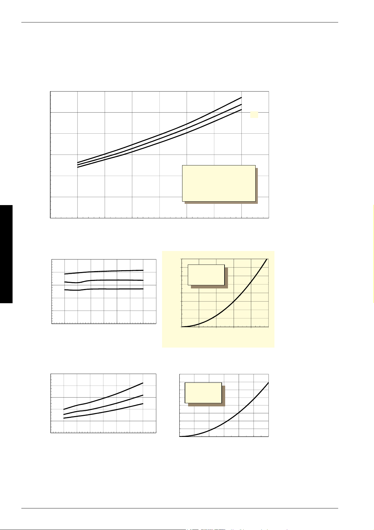
A-IV 452235.66.05 · FD 9310
Anhang · Appendix · Annexes
SI 6TU - SI 18TU
2 Diagramme / Diagrams / Diagrammes
2.1 Kennlinien / Characteristic Curves / Courbes caractéristiques SI 6TU
:DVVHUDXVWULWWVWHPSHUDWXU
LQ>&@
:DWHURXWOHWWHPSHUDWXUHLQ>&@
7HPSpUDWXUHGHVRUWLHGHOHDXHQ>&@
+HL]OHLVWXQJLQ>N:@
+HDWLQJFDSDFLW\LQ>N:@
3XLVVDQFHGHFKDXIIDJHHQ>N:@
6ROHHLQWULWWVWHPSHUDWXULQ>&@Â%ULQHLQOHWWHPSHUDWXUHLQ>&@Â7HPSpUDWXUHGHQWUpHGHDXJO\FROpHHQ>&@
/HLVWXQJVDXIQDKPHLQ>N:@LQFO3XPSHQOHLVWXQJVDQWHLO
3RZHUFRQVXPSWLRQLQ>N:@LQFOSRZHULQSXWWRSXPS
&RQVRPPDWLRQGHSXLVVDQFHLQ>N:@\FRPSULVSDUWGHFRQVRPPDWLRQGHODSRPSH
'UXFNYHUOXVWLQ>3D@
3UHVVXUHORVVLQ>3D@
3HUWHGHSUHVVLRQHQ>3D@
'UXFNYHUOXVWLQ>3D@
3UHVVXUHORVVLQ>3D@
3HUWHGHSUHVVLRQHQ>3D@
6ROHHLQWULWWVWHPSHUDWXULQ>&@
%ULQHLQOHWWHPSHUDWXUHLQ>&@
7HPSpUDWXUHGHQWUpHGHDXJO\FROpHHQ>&@
6ROHGXUFKIOXVVLQ>P
K@
%ULQHIORZUDWHLQ>P
K@
'pELWGHDXJO\FROpHHQ>P
K@
6ROHHLQWULWWVWHPSHUDWXULQ>&@
%ULQHLQOHWWHPSHUDWXUHLQ>&@
7HPSpUDWXUHGHQWUpHGHDXJO\FROpHHQ>&@
/HLVWXQJV]DKOLQFO3XPSHQOHLVWXQJVDQWHLO
&RHIILFLHQWRISHUIRUPDQFHLQFOSRZHULQSXWWRSXPS
&RHIILFLHQWGHSHUIRUPDQFH\FRPSULVSDUWGHFRQVRPPDWLRQGHODSRPSH
+HL]ZDVVHUGXUFKIOXVVLQ>P
K@
+HDWLQJZDWHUIORZUDWHLQ>P
K@
'pELWGHDXGHFKDXIIDJHHQ>P
K@
9HUGDPSIHU
(YDSRUDWRU
(YDSRUDWHXU
9HUIOVVLJHU
&RQGHQVHU
&RQGHQVHXU
%HGLQJXQJHQÂ&RQGLWLRQVÂ&RQGLWLRQV
+HL]ZDVVHUGXUFKVDW] PñK
+HDWLQJZDWHUIORZUDWH
'pELWGHDXGHFKDXIIDJH
6ROHGXUFKVDW]
PñK
%ULQHIORZUDWH
'pELWGHDXJO\FROpH
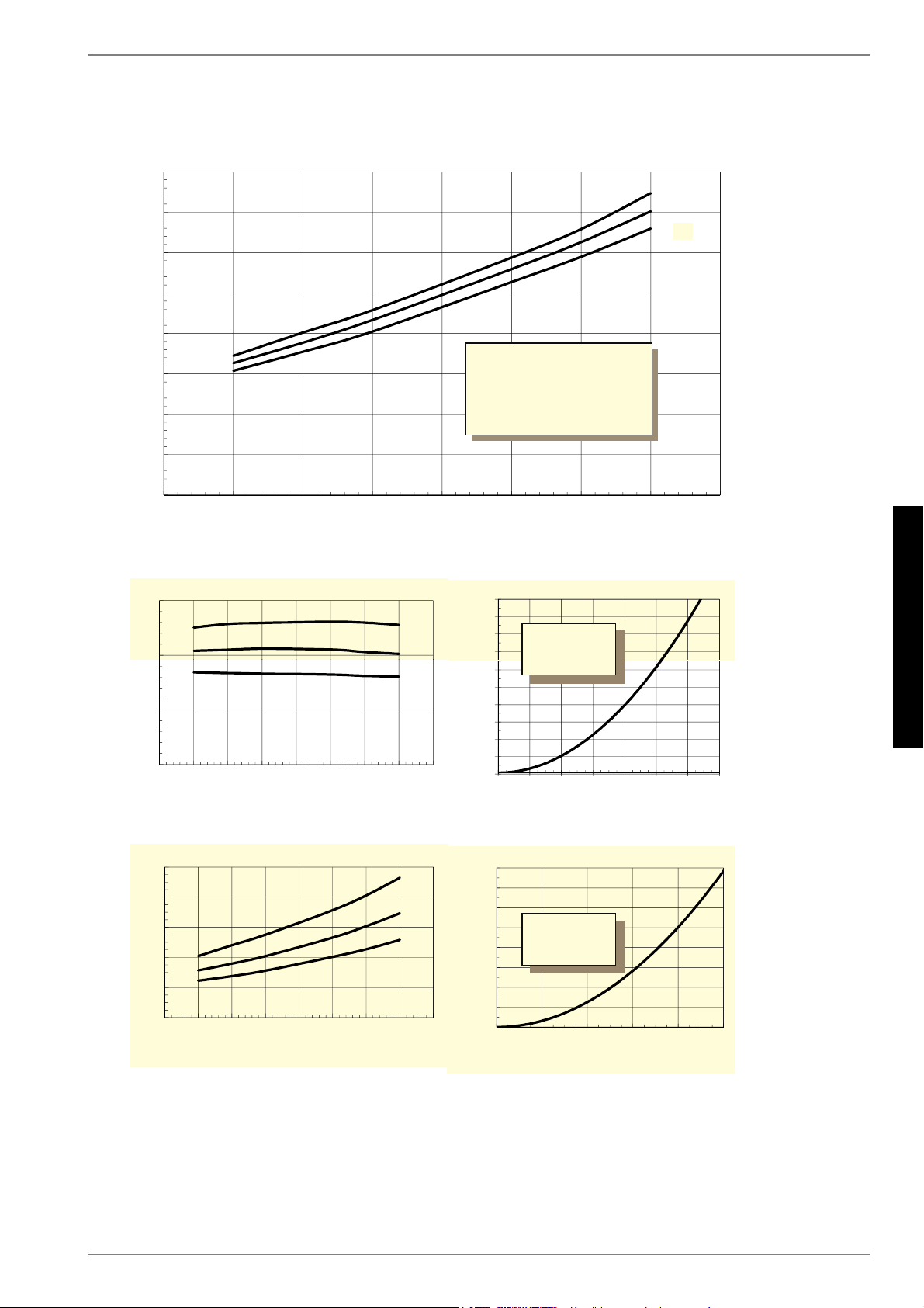
www.dimplex.de 452235.66.05 · FD 9310 A-V
Anhang · Appendix · Annexes
SI 6TU - SI 18TU
2.2 Kennlinien / Characteristic Curves / Courbes caractéristiques SI 8TU
+HL]OHLVWXQJLQ>N:@
+HDWLQJFDSDFLW\LQ>N:@
3XLVVDQFHGHFKDXIIDJHHQ>N:@
6ROHHLQWULWWVWHPSHUDWXULQ>&@Â%ULQHLQOHWWHPSHUDWXUHLQ>&@Â7HPSpUDWXUHGHQWUpHGHDXJO\FROpHHQ>&@
/HLVWXQJVDXIQDKPHLQ>N:@LQFO3XPSHQOHLVWXQJVDQWHLO
3RZHUFRQVXPSWLRQLQ>N:@LQFOSRZHULQSXWWRSXPS
&RQVRPPDWLRQGHSXLVVDQFHLQ>N:@\FRPSULVSDUWGHFRQVRPPDWLRQGHODSRPSH
'UXFNYHUOXVWLQ>3D@
3UHVVXUHORVVLQ>3D@
3HUWHGHSUHVVLRQHQ>3D@
'UXFNYHUOXVWLQ>3D@
3UHVVXUHORVVLQ>3D@
3HUWHGHSUHVVLRQHQ>3D@
6ROHHLQWULWWVWHPSHUDWXULQ>&@
%ULQHLQOHWWHPSHUDWXUHLQ>&@
7HPSpUDWXUHGHQWUpHGHDXJO\FROpHHQ>&@
6ROHGXUFKIOXVVLQ>P
K@
%ULQHIORZUDWHLQ>P
K@
'pELWGHDXJO\FROpHHQ>P
K@
6ROHHLQWULWWVWHPSHUDWXULQ>&@
%ULQHLQOHWWHPSHUDWXUHLQ>&@
7HPSpUDWXUHGHQWUpHGHDXJO\FROpHHQ>&@
/HLVWXQJV]DKOLQFO3XPSHQOHLVWXQJVDQWHLO
&RHIILFLHQWRISHUIRUPDQFHLQFOSRZHULQSXWWRSXPS
&RHIILFLHQWGHSHUIRUPDQFH\FRPSULVSDUWGHFRQVRPPDWLRQGHODSRPSH
+HL]ZDVVHUGXUFKIOXVVLQ>P
K@
+HDWLQJZDWHUIORZUDWHLQ>P
K@
'pELWGHDXGHFKDXIIDJHHQ>P
K@
9HUGDPSIHU
(YDSRUDWRU
(YDSRUDWHXU
9HUIOVVLJHU
&RQGHQVHU
&RQGHQVHXU
%HGLQJXQJHQÂ&RQGLWLRQVÂ&RQGLWLRQV
+HL]ZDVVHUGXUFKVDW] PñK
+HDWLQJZDWHUIORZUDWH
'pELWGHDXGHFKDXIIDJH
6ROHGXUFKVDW] PñK
%ULQHIORZUDWH
'pELWGHDXJO\FROpH
:DVVHUDXVWULWWVWHPSHUDWXULQ
>&@
:DWHURXWOHWWHPSHUDWXUHLQ>&@
7HPSpUDWXUHGHVRUWLHGHOHDXHQ>&@
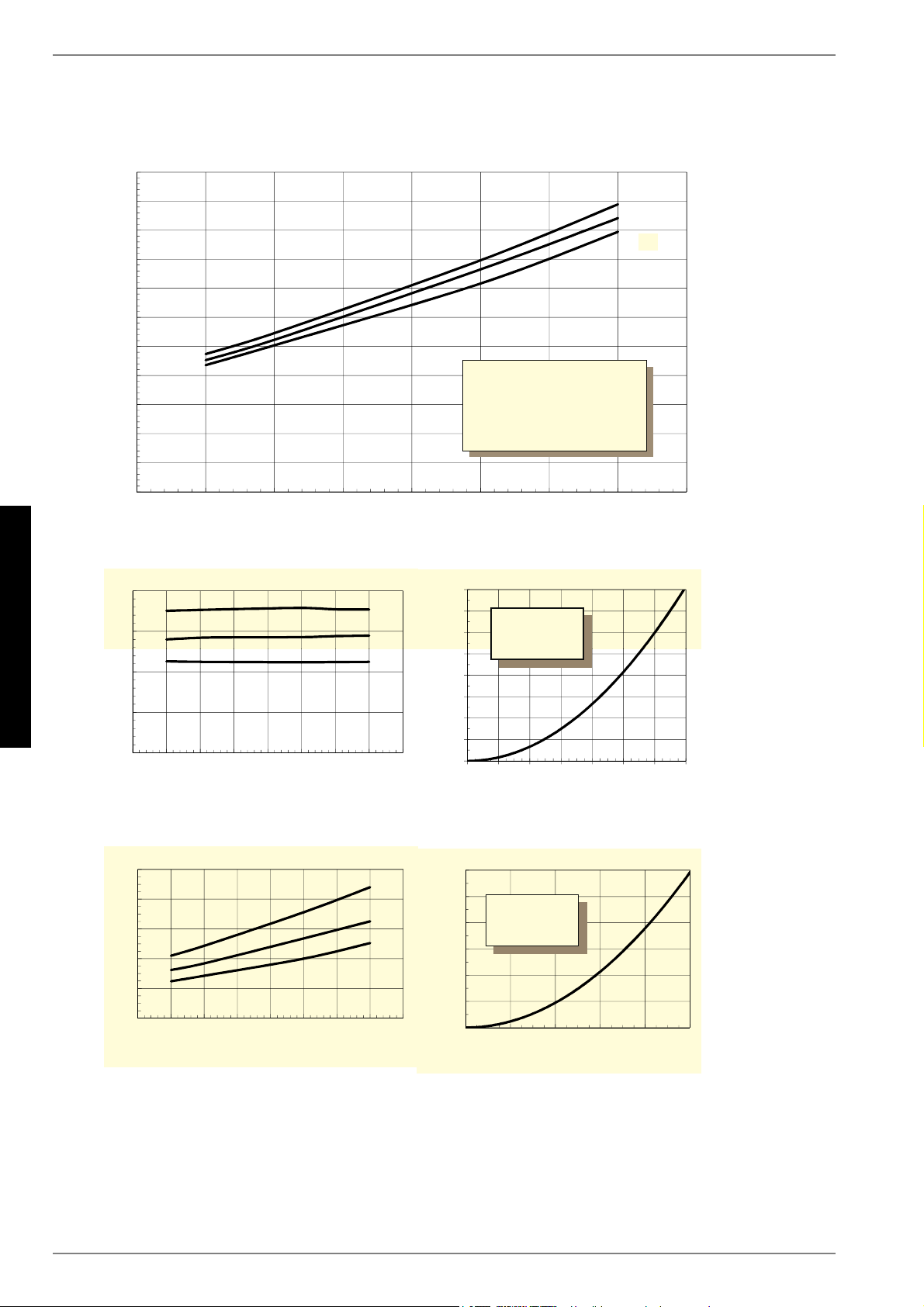
A-VI 452235.66.05 · FD 9310
Anhang · Appendix · Annexes
SI 6TU - SI 18TU
2.3 Kennlinien / Characteristic Curves / Courbes caractéristiques SI 11TU
%HGLQJXQJHQÂ&RQGLWLRQVÂ&RQGLWLRQV
+HL]ZDVVHUGXUFKVDW] PñK
+HDWLQJZDWHUIORZUDWH
'pELWGHDXGHFKDXIIDJH
6ROHGXUFKVDW]
PñK
%ULQHIORZUDWH
'pELWGHDXJO\FROpH
+HL]OHLVWXQJLQ>N:@
+HDWLQJFDSDFLW\LQ>N:@
3XLVVDQFHGHFKDXIIDJHHQ>N:@
6ROHHLQWULWWVWHPSHUDWXULQ>&@Â%ULQHLQOHWWHPSHUDWXUHLQ>&@Â7HPSpUDWXUHGHQWUpHGHDXJO\FROpHHQ>&@
/HLVWXQJVDXIQDKPHLQ>N:@LQFO3XPSHQOHLVWXQJVDQWHLO
3RZHUFRQVXPSWLRQLQ>N:@LQFOSRZHULQSXWWRSXPS
&RQVRPPDWLRQGHSXLVVDQFHLQ>N:@\FRPSULVSDUWGHFRQVRPPDWLRQGHODSRPSH
'UXFNYHUOXVWLQ>3D@
3UHVVXUHORVVLQ>3D@
3HUWHGHSUHVVLRQHQ>3D@
'UXFNYHUOXVWLQ>3D@
3UHVVXUHORVVLQ>3D@
3HUWHGHSUHVVLRQHQ>3D@
6ROHHLQWULWWVWHPSHUDWXULQ>&@
%ULQHLQOHWWHPSHUDWXUHLQ>&@
7HPSpUDWXUHGHQWUpHGHDXJO\FROpHHQ>&@
6ROHGXUFKIOXVVLQ>P
K@
%ULQHIORZUDWHLQ>P
K@
'pELWGHDXJO\FROpHHQ>P
K@
6ROHHLQWULWWVWHPSHUDWXULQ>&@
%ULQHLQOHWWHPSHUDWXUHLQ>&@
7HPSpUDWXUHGHQWUpHGHDXJO\FROpHHQ>&@
/HLVWXQJV]DKOLQFO3XPSHQOHLVWXQJVDQWHLO
&RHIILFLHQWRISHUIRUPDQFHLQFOSRZHULQSXWWRSXPS
&RHIILFLHQWGHSHUIRUPDQFH\FRPSULVSDUWGHFRQVRPPDWLRQGHODSRPSH
+HL]ZDVVHUGXUFKIOXVVLQ>P
K@
+HDWLQJZDWHUIORZUDWHLQ>P
K@
'pELWGHDXGHFKDXIIDJHHQ>P
K@
9HUIOVVLJHU
&RQGHQVHU
&RQGHQVHXU
9HUGDPSIHU
(YDSRUDWRU
(YDSRUDWHXU
:DVVHUDXVWULWWVWHPSHUDWXULQ
>&@
:DWHURXWOHWWHPSHUDWXUHLQ>&@
7HPSpUDWXUHGHVRUWLHGHOHDXHQ>&@
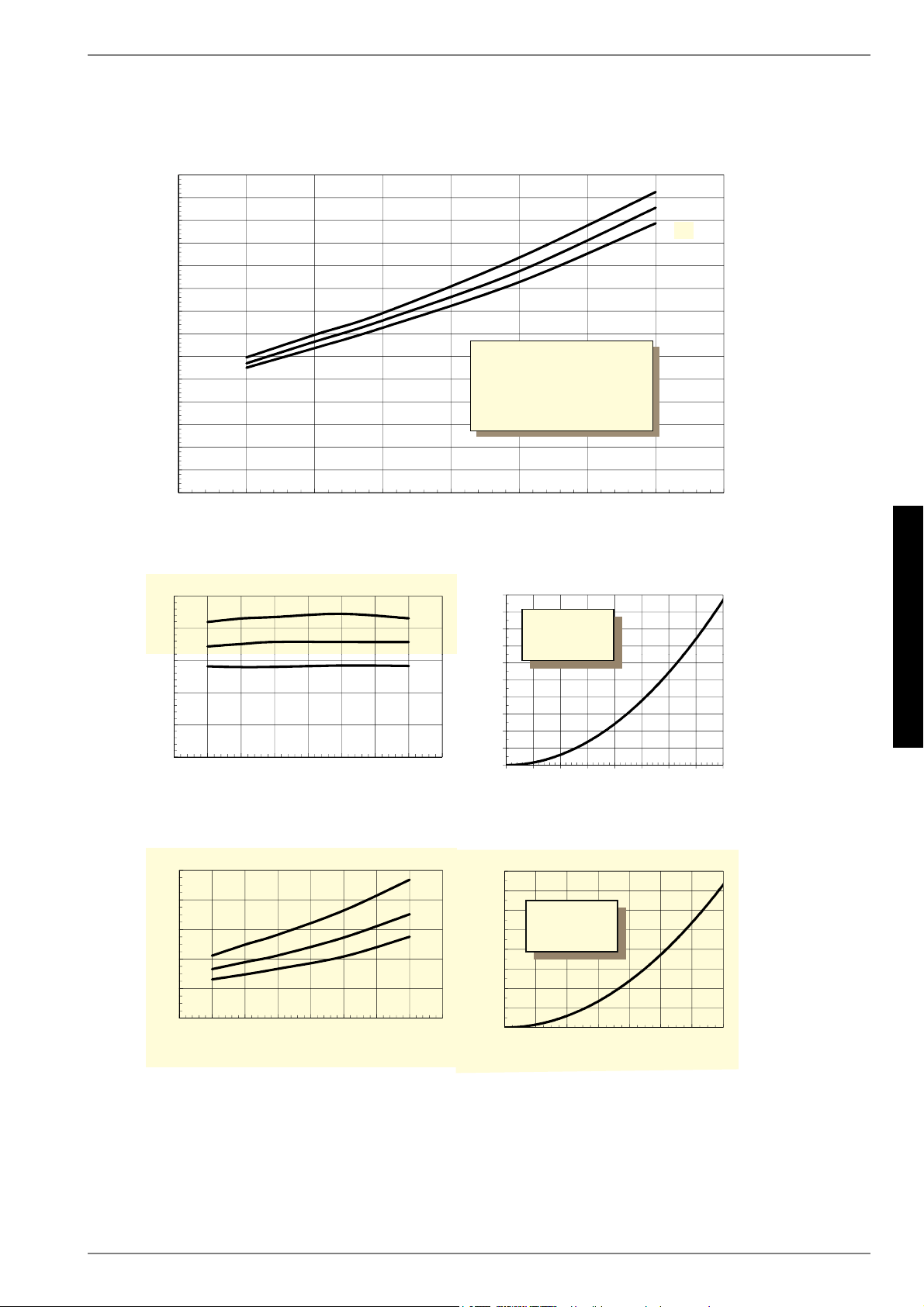
www.dimplex.de 452235.66.05 · FD 9310 A-VII
Anhang · Appendix · Annexes
SI 6TU - SI 18TU
2.4 Kennlinien / Characteristic Curves / Courbes caractéristiques SI 14TU
+HL]OHLVWXQJLQ>N:@
+HDWLQJFDSDFLW\LQ>N:@
3XLVVDQFHGHFKDXIIDJHHQ>N:@
6ROHHLQWULWWVWHPSHUDWXULQ>&@Â%ULQHLQOHWWHPSHUDWXUHLQ>&@Â7HPSpUDWXUHGHQWUpHGHDXJO\FROpHHQ>&@
/HLVWXQJVDXIQDKPHLQ>N:@LQFO3XPSHQOHLVWXQJVDQWHLO
3RZHUFRQVXPSWLRQLQ>N:@LQFOSRZHULQSXWWRSXPS
&RQVRPPDWLRQGHSXLVVDQFHLQ>N:@\FRPSULVSDUWGHFRQVRPPDWLRQGHODSRPSH
'UXFNYHUOXVWLQ>3D@
3UHVVXUHORVVLQ>3D@
3HUWHGHSUHVVLRQHQ>3D@
'UXFNYHUOXVWLQ>3D@
3UHVVXUHORVVLQ>3D@
3HUWHGHSUHVVLRQHQ>3D@
6ROHHLQWULWWVWHPSHUDWXULQ>&@
%ULQHLQOHWWHPSHUDWXUHLQ>&@
7HPSpUDWXUHGHQWUpHGHDXJO\FROpHHQ>&@
6ROHGXUFKIOXVVLQ>P
K@
%ULQHIORZUDWHLQ>P
K@
'pELWGHDXJO\FROpHHQ>P
K@
6ROHHLQWULWWVWHPSHUDWXULQ>&@
%ULQHLQOHWWHPSHUDWXUHLQ>&@
7HPSpUDWXUHGHQWUpHGHDXJO\FROpHHQ>&@
/HLVWXQJV]DKOLQFO3XPSHQOHLVWXQJVDQWHLO
&RHIILFLHQWRISHUIRUPDQFHLQFOSRZHULQSXWWRSXPS
&RHIILFLHQWGHSHUIRUPDQFH\FRPSULVSDUWGHFRQVRPPDWLRQGHODSRPSH
+HL]ZDVVHUGXUFKIOXVVLQ>P
K@
+HDWLQJZDWHUIORZUDWHLQ>P
K@
'pELWGHDXGHFKDXIIDJHHQ>P
K@
9HUIOVVLJHU
&RQGHQVHU
&RQGHQVHXU
%HGLQJXQJHQÂ&RQGLWLRQVÂ&RQGLWLRQV
+HL]ZDVVHUGXUFKVDW] PñK
+HDWLQJZDWHUIORZUDWH
'pELWGHDXGHFKDXIIDJH
6ROHGXUFKVDW]
PñK
%ULQHIORZUDWH
'pELWGHDXJO\FROpH
9HUGDPSIHU
(YDSRUDWRU
(YDSRUDWHXU
:DVVHUDXVWULWWVWHPSHUDWXULQ
>&@
:DWHURXWOHWWHPSHUDWXUHLQ>&@
7HPSpUDWXUHGHVRUWLHGHOHDXHQ>&@
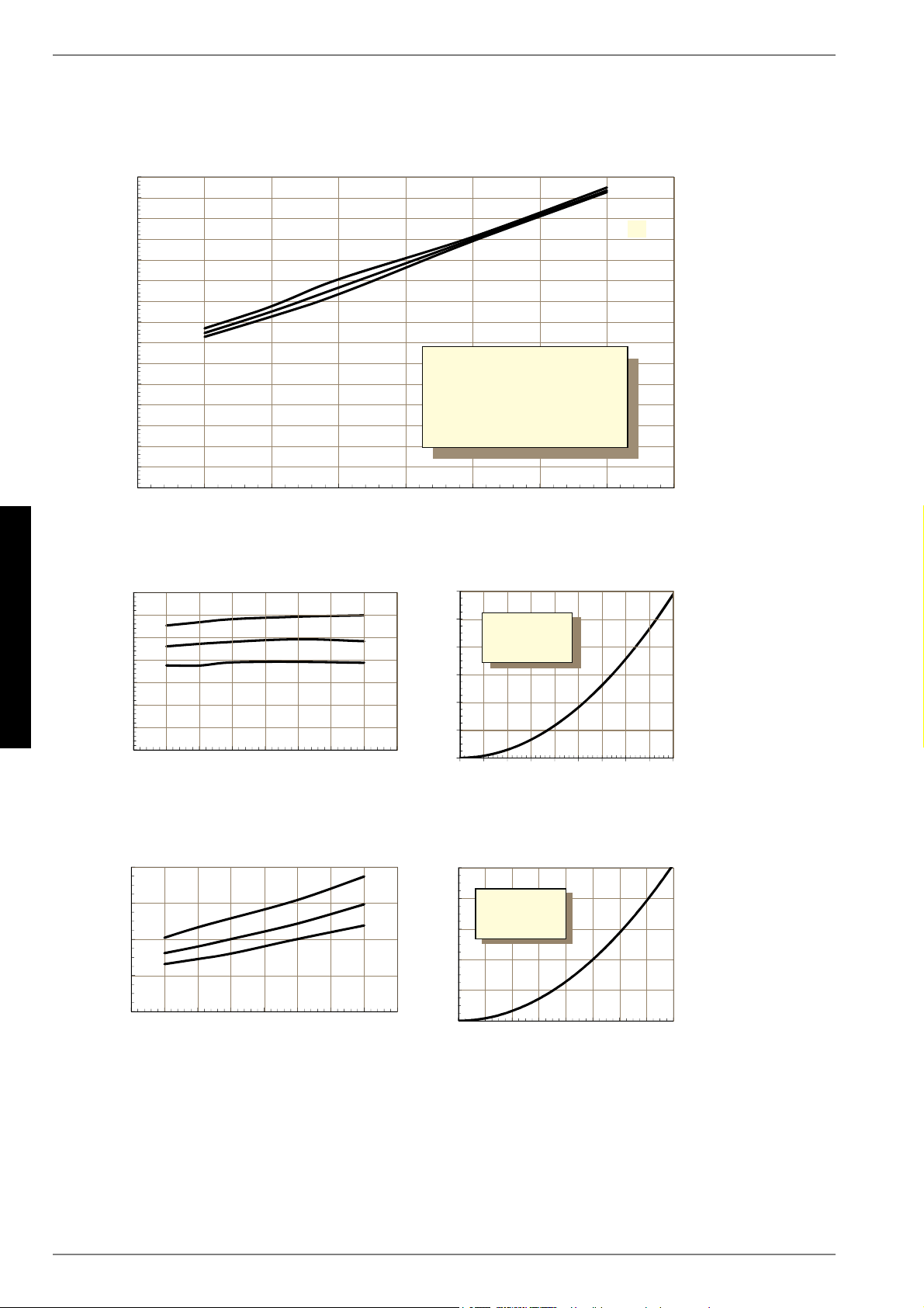
A-VIII 452235.66.05 · FD 9310
Anhang · Appendix · Annexes
SI 6TU - SI 18TU
2.5 Kennlinien / Characteristic Curves / Courbes caractéristiques SI 18TU
+HL]OHLVWXQJLQ>N:@
+HDWLQJFDSDFLW\LQ>N:@
3XLVVDQFHGHFKDXIIDJHHQ>N:@
:DVVHUDXVWULWWVWHPSHUDWXULQ>&@
:DWHURXWOHWWHPSHUDWXUHLQ>&@
7HPSpUDWXUHGHVRUWLHGHOHDXHQ>&@
6ROHHLQWULWWVWHPSHUDWXULQ>&@Â%ULQHLQOHWWHPSHUDWXUHLQ>&@Â7HPSpUDWXUHGHQWUpHGHDXJO\FROpHHQ>&@
/HLVWXQJVDXIQDKPHLQ>N:@LQFO3XPSHQOHLVWXQJVDQWHLO
3RZHUFRQVXPSWLRQLQ>N:@LQFOSRZHULQSXWWRSXPS
&RQVRPPDWLRQGHSXLVVDQFHLQ>N:@\FRPSULVSDUWGHFRQVRPPDWLRQGHODSRPSH
'UXFNYHUOXVWLQ>3D@
3UHVVXUHORVVLQ>3D@
3HUWHGHSUHVVLRQHQ>3D@
'UXFNYHUOXVWLQ>3D@
3UHVVXUHORVVLQ>3D@
3HUWHGHSUHVVLRQHQ>3D@
6ROHHLQWULWWVWHPSHUDWXULQ>&@
%ULQHLQOHWWHPSHUDWXUHLQ>&@
7HPSpUDWXUHGHQWUpHGHDXJO\FROpHHQ>&@
6ROHGXUFKIOXVVLQ>P
K@
%ULQHIORZUDWHLQ>P
K@
'pELWGHDXJO\FROpHHQ>P
K@
6ROHHLQWULWWVWHPSHUDWXULQ>&@
%ULQHLQOHWWHPSHUDWXUHLQ>&@
7HPSpUDWXUHGHQWUpHGHDXJO\FROpHHQ>&@
/HLVWXQJV]DKOLQFO3XPSHQOHLVWXQJVDQWHLO
&RHIILFLHQWRISHUIRUPDQFHLQFOSRZHULQSXWWRSXPS
&RHIILFLHQWGHSHUIRUPDQFH\FRPSULVSDUWGHFRQVRPPDWLRQGHODSRPSH
+HL]ZDVVHUGXUFKIOXVVLQ>P
K@
+HDWLQJZDWHUIORZUDWHLQ>P
K@
'pELWGHDXGHFKDXIIDJHHQ>P
K@
9HUIOVVLJHU
&RQGHQVHU
&RQGHQVHXU
9HUGDPSIHU
(YDSRUDWRU
(YDSRUDWHXU
%HGLQJXQJHQÂ&RQGLWLRQVÂ&RQGLWLRQV
+HL]ZDVVHUGXUFKVDW] PñK
+HDWLQJZDWHUIORZUDWH
'pELWGHDXGHFKDXIIDJH
6ROHGXUFKVDW]
PñK
%ULQHIORZUDWH
'pELWGHDXJO\FROpH
www.dimplex.de 452235.66.05 · FD 9310 A-IX
Anhang · Appendix · Annexes
SI 6TU - SI 18TU
2.6 Einsatzgrenzendiagramm / Operating limits diagram /
Diagramme des seuils d'utilisation SI 6TU - SI 18TU
0
5
10
15
20
25
30
35
40
45
50
55
60
65
-10-5 0 5 1015202530
Heizwassertemperatur [°C] / Heating water temperature [°C] / Température d'eau de chauffage [°C]
Wärmequelleneintrittstemperatur [°C]
Heat source inlet temperature [°C]
Température d'entrée de la source de chaleur [°C]
Wasseraustritt (+/- 2 K)
Water outlet (+/- 2 K)
Sortie d'eau (+/- 2 K)
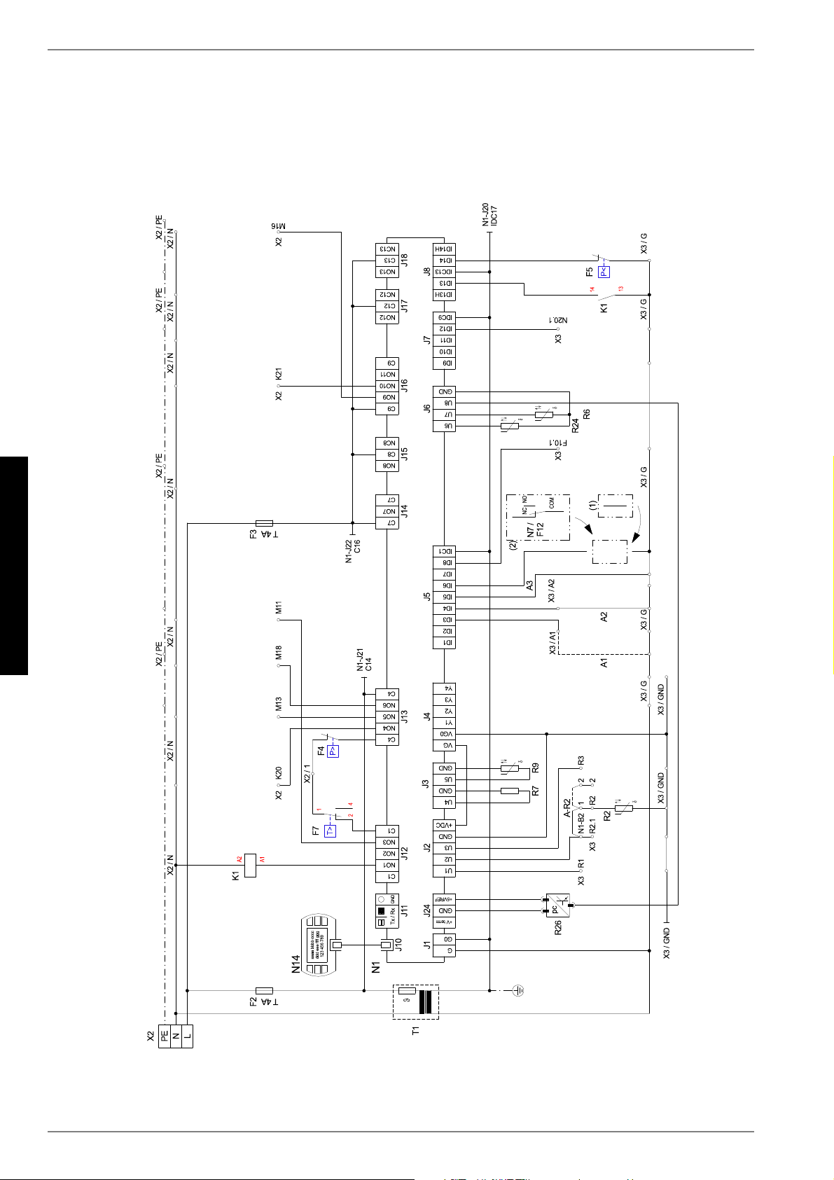
A-X 452235.66.05 · FD 9310
Anhang · Appendix · Annexes
SI 6TU - SI 18TU
3 Stromlaufpläne / Circuit Diagrams / Schémas
électriques
3.1 Steuerung / Control / Commande
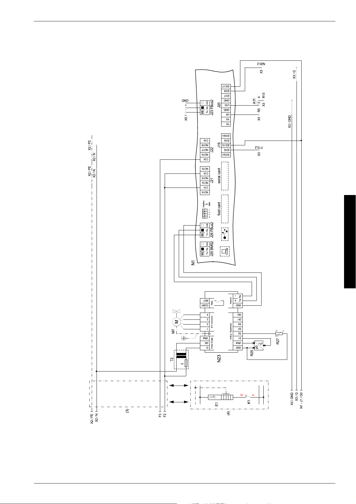
www.dimplex.de 452235.66.05 · FD 9310 A-XI
Anhang · Appendix · Annexes
SI 6TU - SI 18TU
3.2 Steuerung / Control / Commande
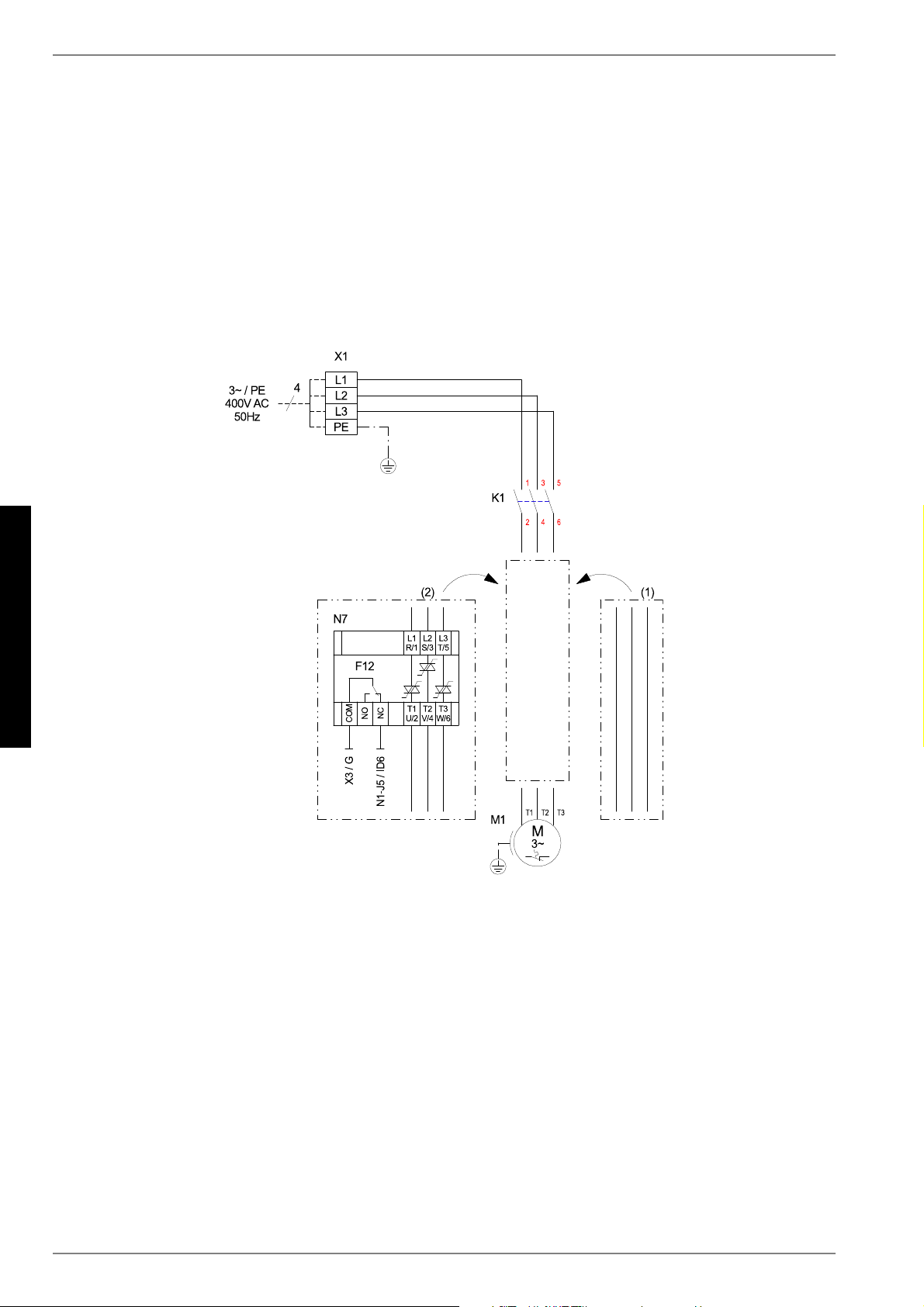
A-XII 452235.66.05 · FD 9310
Anhang · Appendix · Annexes
SI 6TU - SI 18TU
3.3 Last / Load / Charge
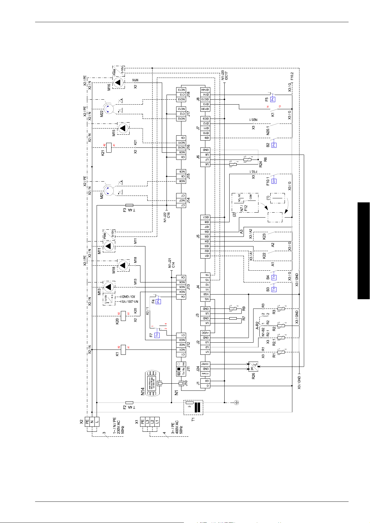
www.dimplex.de 452235.66.05 · FD 9310 A-XIII
Anhang · Appendix · Annexes
SI 6TU - SI 18TU
3.4 Anschlussplan / Connection Plan / Schéma de connexion
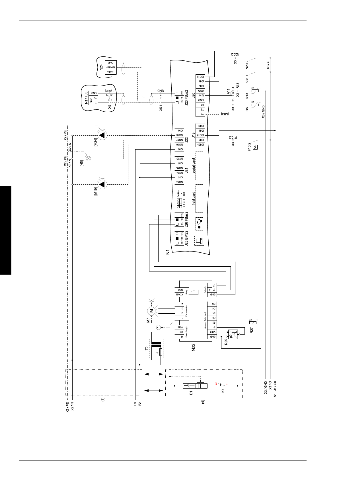
A-XIV 452235.66.05 · FD 9310
Anhang · Appendix · Annexes
SI 6TU - SI 18TU
3.5 Anschlussplan / Connection Plan / Schéma de connexion

www.dimplex.de 452235.66.05 · FD 9310 A-XV
Anhang · Appendix · Annexes
SI 6TU - SI 18TU
3.6 Legende / Legend / Légende
A1 Brücke EVU-Sperre, muss eingelegt werden, wenn
kein EVU-Sperrschütz vorhanden ist
(Kontakt offen = EVU-Sperre
Utility block (EVU) bridge must be inserted if no
utility blocking contactor is present
(contact open = utility block).
Pont de blocage de la société d'électricité, à insérer
en absence de contacteur de blocage de la société
d'électricité
(contact ouvert = blocage de la société d'électricité)
A2 Brücke Sperre: muss entfernt werden, wenn der
Eingang genutzt wird
(Eingang offen = WP gesperrt)
Block bridge: Must be removed when the input is
being used
(input open = HP blocked).
Pont de blocage : à retirer si l’entrée est utilisée
(entrée ouverte = pompe à chaleur bloquée)
A3 Brücke Störung M11: muß entfernt werden, wenn
der Eingang gnutzt wird
(Eingang offen = Störung M11)
M11 link cable fault: must be removed when the
input is being used
(input open = M11 fault)
Pont défaut M11 : à retirer si l'entrée est utilisée
(entrée ouverte = défaut M11)
A11 Brücke Solar: bei Verwendung eines Solarmoduls
muss die Brücke entfernt werden und die Klemm-
stellen mit dem Solar-Modul verbunden werden.
Solar bridge: When a solar energy module is used,
the bridge must be removed and the solar energy
module connected to the terminal connections.
Pont solaire : en cas d'utilisation d'un module
solaire, retirer le pont et connecter les bornes au
module solaire.
A - R2 Brücke Rücklauffühler: - muss versetzt werden,
wenn doppelt differenzdruckloser Verteiler und
„Heizkreisumkehrventil“ verwendet wird.
Neue Klemmstellen: X3 / 1 und X3 / 2
Return sensor bridge: - Must be moved when a dual
differential pressureless manifold and a “heating
circuit reversing valve” are used.
New terminal connections: X3/1 and X3/2
Pont sonde sur circuit de retour : - à déplacer si le
distributeur double sans pression différentielle et la
« vanne d’inversion du circuit de chauffage » sont
utilisés.
Nouveaux emplacements de borne : X3 / 1 et X3 / 2
B2* Pressostat Niederdruck Primärkreis Low-pressure controller, primary circuit Pressostat basse pression circuit primaire
B3* Thermostat Warmwasser Hot water thermostat Thermostat eau chaude
B4* Thermostat Schwimmbadwasser Swimming pool water thermostat Thermostat eau de piscine
E1 Ölsumpfheizung Oil sump heater Chauffage à carter d’huile
E9* Tauchheizkörper Warmwasser) Immersion heater for hot water Résistance immergée eau chaude sanitaire
E10* 2. Wärmeerzeuger 2ndheat generator 2ème générateur de chaleur
F2 Sicherung für Steckklemmen J12; J13 und J21
5x20 / 4,0AT
Fuse for plug-in terminals J12; J13 and J21
5x20 / 4.0AT
Fusible pour bornes enfichables J12 ; J13 et J21
5x20 / 4,0AT
F3 Sicherung für Steckklemmen J15 bis J18 und J22
5x20 / 4,0AT
Fuse for plug-in terminals J15 to J18 and J22
5x20 / 4.0AT
Fusible pour bornes enfichables J15 à J18 et J22
5x20 / 4,0AT
F4 Hochdruckpressostat High-pressure switch Pressostat haute pression
F5 Niederdruckpressestat Low-pressure switch Pressostat basse pression
F7 Heißgasthermostat Hot gas thermostat Thermostat gaz chaud
F10.1* Durchflussschalter Primärkreis Flow rate switch for primary circuit Commutateur de débit circuit primaire
F10.2* Durchflussschalter Sekundärkreis Flow rate switch for secondary circuit Commutateur de débit circuit secondaire
F12 Störmeledekontakt N7 Fault signaling contact N7 Contact de signalisation de défauts N7
[H5]* Leuchte Störfernanzeige Remote fault indicator lamp Témoin de télédétection de pannes
J1 Spannungsversorgung Voltage supply Alimentation en tension
J2-3 Analogeingänge Analogue inputs Entrées analogiques
J4 Analogausgänge Analogue outputs Sorties analogiques
J5 Digitaleingänge Digital inputs Entrées numériques
J6 Analogausgänge Analogue outputs Sorties analogiques
J7-8 Digitaleingänge Digital inputs Entrées numériques
J10 Bedienteil Control panel Unité de commande
J11 frei free libre
J12-J18 230 V AC - Ausgänge 230V AC outputs 230 V AC - outputs Sorties 230 V AC
J19 Digitaleingänge Digital inputs Entrées numériques
J20 Analogausgänge; Analogeingänge,
Digitaleingänge
Analogue outputs; Analogue inputs, Digital inputs Sorties analogiques, entrées analogiques,
entrées numériques
J21-22 Digitalausgänge Digital outputs Sorties numériques
J23 Bus-Verbindung zu Modulen Bus connection to modules Raccordement Bus aux modules
J24 Spannungsversorgung für Komponenten Power supply for components Alimentation en tension des composants
J25 Schnittstelle Interface Interface
J26 Bus - Verbindung intern Bus connection internal Raccordement interne au bus
K1 Schütz M1 Contactor M1 Contacteur M1
K20* Schütz E10 Contactor E10 Contacteur E10
K21* Schütz E9 Contactor E9 Contacteur E9
K22* EVU-Sperrschütz Utility blocking contactor Contacteur de coupure du fournisseur d'énergie
K23* Hilfsrelais für Sperreingang Auxiliary relay for disable contactor Relais auxiliaire pour entrée du contacteur de
blocage
K31.1* Anforderung Zirkulation Warmwasser Domestic hot water circulation request Demande circulation ECS
M1 Verdichter Compressor Compresseur
M7 Stellmotor für Expansionsventil Actuator for expansion valve Servomoteur pour détendeur
M11* Primärkreispumpe Primary circuit pump Pompe circuit primaire
M13* Heizungsumwälzpumpe Heat circulating pump Circulateur de chauffage
M15* Heizungsumwälzpumpe 2. Heizkreis Heat circulating pump for heating circuit 2 Circulateur de chauffage pour le 2e circuit
de chauffage
M16* Zusatzumwälzpumpe Auxiliary circulating pump Circulateur supplémentaire
M18* Warmwasserladepumpe Hot water loading pump Pompe de charge eau chaude sanitaire
[M19]* Schwimmbadwasserumwälzpumpe Swimming pool circulating pump Circulateur de la piscine
M21* Mischer Hauptkreis oder 3. Heizkreis Mixer for main circuit or heating circuit 3 Mélangeur circuit principal ou 3ème circuit de
chauffage
M22* Mischer 2. Heizkreis Mixer for heating circuit 2 Mélangeur 2e circuit de chauffage
[M24]* Zirkulationspumpe Warmwasser Domestic hot water circulating pump Pompe de circulation eau chaude sanitaire
N1 Regeleinheit Control unit Unité de régulation
N7 Sanftanlaufsteuerung M1 Soft start control M1 Commande de démarrage progressif M1
N14 Bedienteil Control panel Unité de commande
N17* pCOe-Modul pCOe module Module pCOe
N20 Wärmemengenzähler Thermal energy meter Compteur de chaleur
N23 Ansteuerung elektronisches Expansionsventil E*V
connection (1 = grün; 2 = gelb; 3 = braun; 4 = weiß)
Control for electronic expansion valve E*V
connection (1=green; 2=yellow; 3=brown; 4=white)
Commande détendeur électronique connexion E*V
(1=vert ; 2=jaune ; 3=marron ; 4=blanc)
N24* Smart RTC Smart RTC Smart RTC
R1* Außenfühler External sensor Sonde extérieure
R2 Rücklauffühler Heizkreis Return sensor for heating circuit Sonde de retour circuit de chauffage
R2.1* Rücklauffühler Heizkreis im
doppelt differenzdrucklosen-Verteiler
Return sensor for heating circuit in dual differential
pressureless manifold
Sonde de retour circuit de chauffage dans le
distributeur double sans pression différentielle
R3* Warmwasserfühler Hot water sensor Sonde d’eau chaude

A-XVI 452235.66.05 · FD 9310
Anhang · Appendix · Annexes
SI 6TU - SI 18TU
R5* Fühler 2. Heizkreis Sensor for heating circuit 2 Sonde pour 2e circuit de chauffage
R6 Vorlauffühler Primärkreis Flow sensor for primary circuit Sonde aller circuit primaire
R7 Codierwiderstand Coding resistor Résistance de codage
R9 Vorlauffühler Heizkreis Flow sensor for heating circuit Sonde aller circuit de chauffage
R13* Fühler regenerativ, Raumfühler, Fühler 3. Heizkreis Renewable sensor, room sensor, sensor for
heating circuit 3
Sonde mode régénératif, sonde d'ambiance, sonde
3ème circuit de chauffage
R24 Rücklauffühler Primärkreis Return sensor, primary circuit Sonde retour circuit primaire
R25 Drucksensor Kältekreis - Niederdruck pO Pressure sensor for refrigerating circuit -
low pressure pO
Capteur de pression circuit réfrigérant -
basse pression pO
R26 Drucksensor Kältekreis - Hochdruck pc Pressure sensor for refrigerating circuit -
high pressure pc
Capteur de pression circuit réfrigérant -
haute pression pc
R27 Sauggasfühler Suction gas sensor Sonde de gaz d'aspiration
T1 Sicherheitstransformator 230 / 24 V AC - Regelung Safety transformer 230 / 24 V AC - regulation Transformateur de sécurité 230 / 24 VAC -
Régulation
T2 Sicherheitstransformator 230 / 24 V AC - N23 Safety transformer 230 / 24 V AC - N23 Transformateur de sécurité 230 / 24 V AC - N23
X1 Klemmleiste Einspeisung Last Terminal strip, infeed Alimentation bornier
X2 Klemmleiste Spannung = 230 V AC Terminal strip voltage = 230 V AC Tension bornier = 230 V AC
X3 Klemmleiste Kleinspannung < 25 V AC Terminal strip, extra-low voltage < 25 V AC Faible tension bornier < 25 V AC
X5.1 Busverteilerklemme Bus distribution board terminal Réglettes Bus
* Bauteile sind bauseits anzuschließen / beizustellen Components must be connected / supplied by the
customer
Les pièces sont à raccorder / à fournir par le client
[ ] Flexible Beschaltung - siehe Vorkonfiguration
(Änderung nur durch Kundendienst!)
Flexible switching - see pre-configuration (changes
by after-sales service only!)
Commande flexible - voir pré-configuration
(modification uniquement par le SAV !)
–––––– werksseitig verdrahtet Wired ready for use câblé en usine
- - - - - - bauseits bei Bedarf anzuschließen To be connected by the customer as required À raccorder par le client au besoin
(1) nur bei SI 6TU only in case of SI 6TU uniquement pour SI 6TU
(2) nur bei SI 8TU, SI 11TU, SI 14TU, SI 18TU only in case of SI 8TU, SI 11TU, SI 14TU, SI 18TU uniquement pour SI 8TU, SI 11TU, SI 14TU,
SI 18TU
(3) nur bei SI 6TU, SI 8TU, SI 11TU, SI 14TU only in case of SI 6TU, SI 8TU, SI 11TU, SI 14TU uniquement pour SI 6TU, SI 8TU, SI 11TU,
SI 14TU
(4) nur bei SI 18TU only in case of SI 18TU uniquement pour SI 18TU
ACHTUNG!
An den Steckklemmen N1-J1 bis J11, J19, J20;
J23 bis J26 und den Klemmleisten X3, X5.1
liegt Kleinspannung an. Auf keinen Fall darf
hier eine höhere Spannung angelegt werden.
ATTENTION!
Plug-in terminals N1-J1 to J11, J19, J20, J23 to
J26 and terminal strip X3, X5.1 are connected
to extra-low voltage. A higher voltage must on
no account be connected.
ATTENTION !
Une faible tension est appliquée aux bornes
enfichables N1-J1 à J11, J19, J20, J23 à J24 et
au bornier X3, X5.1. Ne jamais appliquer une
tension plus élevée.
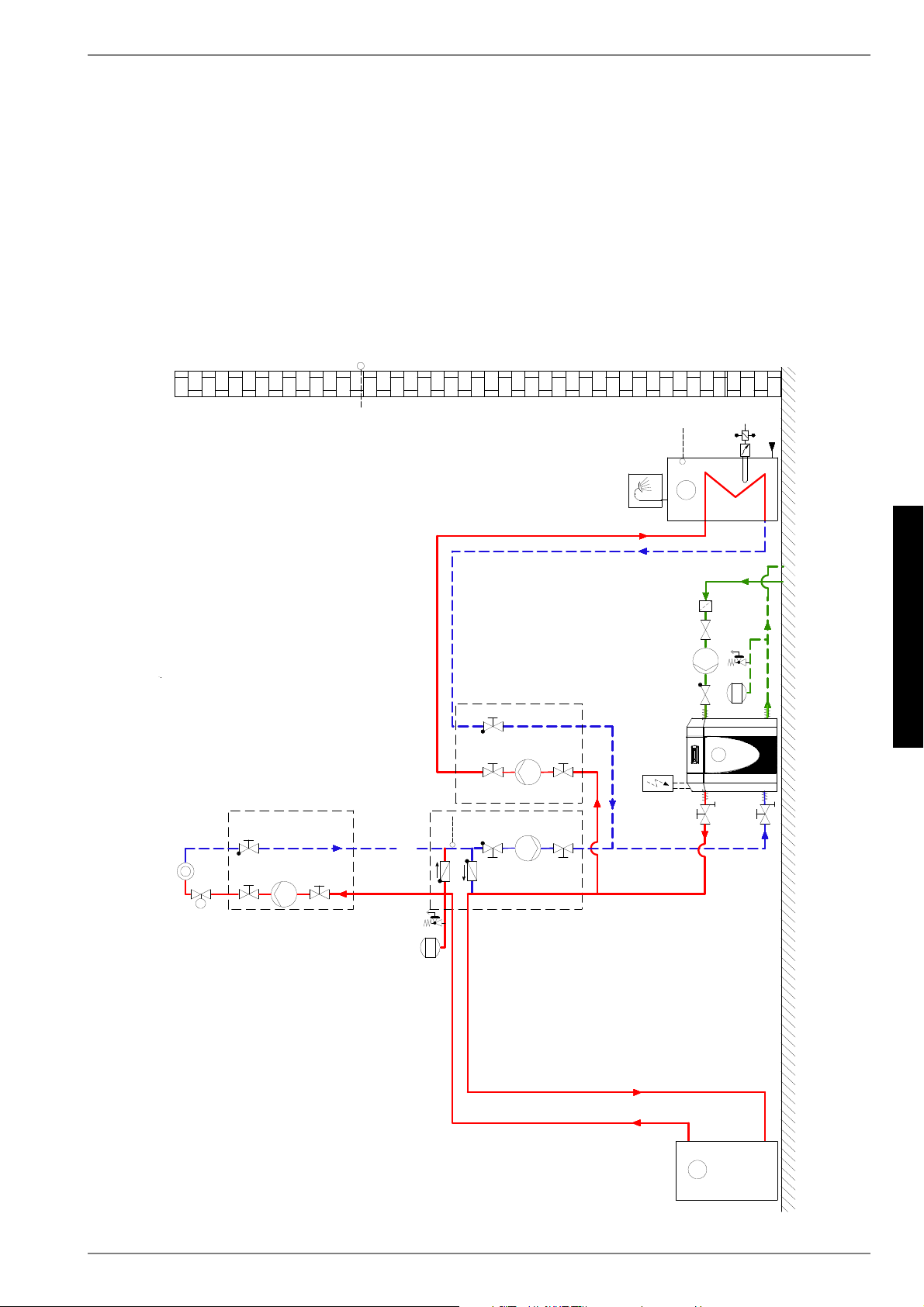
www.dimplex.de 452235.66.05 · FD 9310 A-XVII
Anhang · Appendix · Annexes
SI 6TU - SI 18TU
4 Hydraulisches Einbindungsschema / Hydraulic
integration diagram /
Schéma d'intégration hydraulique
4.1 Monovalente Wärmepumpenanlage mit einem Heizkreis und
Warmwasserbereitung / Monovalent heat pump system with one
heating circuits and domestic hot water preparation / Installation
monovalente de pompe à chaleur avec une circuits de chauffage et
production d'eau chaude sanitaire
5
7
0
(
5
7
5
7
0
;.
;5
;5
;0
;0
;0
0
;5
''9
::0
7&
0;0
1
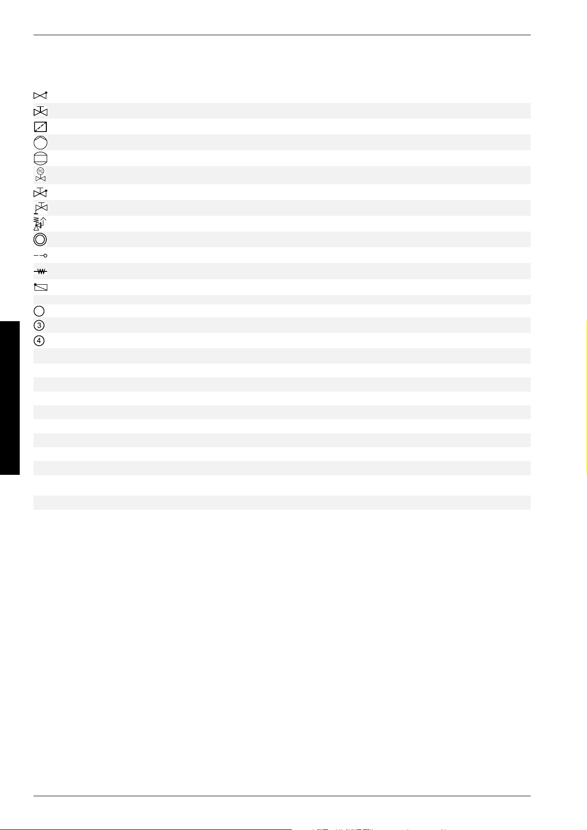
A-XVIII 452235.66.05 · FD 9310
Anhang · Appendix · Annexes
SI 6TU - SI 18TU
4.2 Legende / Legend / Légende
Rückschlagventil Check valve Clapet anti-retour
Absperrventil Shutoff valve Robinet d’arrêt
Schmutzfänger Dirt trap Filtre
Umwälzpumpe Circulating pump Circulateur
Ausdehnungsgefäß Expansion vessel Vase d´expansion
Raumtemperaturgesteuertes Ventil Room temperature-controlled valve
Vanne commandée par
température ambiante
Absperrventil mit Rückschlagventil Shutoff valve with check valve Robinet d’arrêt avec clapet anti-retour
Absperrventil mit Entwässerung Shutoff valve with drainage Robinet d'arrêt avec écoulement
Sicherheitsventilkombination Safety valve combination Groupe de valves de sécurité
Wärmeverbraucher Heat consumer Consommateur de chaleur
Temperaturfühler Temperature sensor Sonde de température
Flexibler Anschlussschlauch Flexible connection hose Tuyau de raccord flexible
Rückschlagklappe Check valve Clapet anti-retour
Sole/Wasser-Wärmepumpe Brine-to-water heat pump Pompe à chaleur eau glycolée-eau
Reihen-Pufferspeicher Buffer tank connected in series Ballon tampon en série
Warmwasserspeicher Hot water cylinder Ballon d’eau chaude sanitaire
E9 Flanschheizung Warmwasser Flange heater, hot water Cartouche chauffante ECS
K21 Schütz Flanschheizung Contactor for flange heater Contacteur cartouche chauffante
M11 Primärumwälzpumpe Primary circulating pump Circulateur primaire
M13 Heizungsumwälzpumpe Heat circulating pump Circulateur de chauffage
M16 Zusatzumwälzpumpe Auxiliary circulation pump Circulateur supplémentaire
M18 Warmwasserladepumpe Hot water loading pump Pompe de charge eau chaude sanitaire
N1 Wärmepumpenmanager Heat pump manager Gestionnaire de pompe à chaleur
R1 Außenwandfühler External wall sensor Sonde sur mur extérieur
R2.1 Zusatzrücklauffühler Additional return flow sensor
Sonde supplémentaire sur circuit de
retour
R3 Warmwasserfühler Hot water sensor Sonde sur circuit d’eau chaude sanitaire

www.dimplex.de 452235.66.05 · FD 9310 A-XIX
Anhang · Appendix · Annexes
SI 6TU - SI 18TU
5 Konformitätserklärung / Declaration of Conformity /
Déclaration de conformité
EG - Konformitätserklärung
EC Declaration of Conformity
Déclaration de conformité CE
Der Unterzeichnete Glen Dimplex Deutschland GmbH
The undersigned Geschäftsbereich Dimplex
L’entreprise soussignée, Am Goldenen Feld 18
D - 95326 Kulmbach
bestätigt hiermit, dass das (die)
nachfolgend bezeichnete(n) Gerät(e)
den nachfolgenden einschlägigen EG-
Richtlinien entspricht. Bei jeder
Änderung des (der) Gerät(e)s verliert
diese Erklärung ihre Gültigkeit.
hereby certifies that the following
device(s) complies/comply with the
applicable EU directives. This
certification loses its validity if the
device(s) is/are modified.
certifie par la présente que le(s)
appareil(s) décrit(s) ci-dessous sont
conformes aux directives CE
afférentes. Toute modification effectuée
sur l’(les) appareil(s) entraîne
l’annulation de la validité de cette
déclaration.
Bezeichnung: Wärmepumpen
Designation: Heat pumps
Désignation: Pompes à chaleur
Typ: SI 6TU
Type(s): SI 8TU
Type(s): SI 11TU
SI 14TU
SI 18TU
EG-Richtlinien
Niederspannungsrichtlinie 2006/96/EG
EMV-Richtlinie 2004/108/EG
Druckgeräterichtlinie 97/23/EG
EC Directives
Low voltage directive 2006/95/EC
EMC directive 2004/108/EC
Pressure equipment directive 97/23/EC
Directives CEE
Directive Basse Tension 2006/95/CE
Directive CEM 2004/108/CE
Directive Équipement Sous Pression
97/23/CE
Angewandte Normen
Applied standards Normes appliquées
EN 60335-1+A11+A1+A12+Corr.+A2
EN 60335-1/A13
EN 60335-2-40+A11+A12+A1+Corr.+A2
EN 55014-1
EN 55014-2+A1
EN 61000-3-2
EN 61000-3-3+A1:2001+A2
EN 378-1, EN 378-2+A1, EN 378-3, EN 378-4
EN 14511-1, EN 14511-2, EN 14511-3+EN 14511-3/AC, EN 14511-4
DIN 8901
BGR 500 (D), SVTI (CH)
Konformitätsbewertungsverfahren
nach Druckgeräterichtlinie:
Modul A
Conformity assessment procedure
according to pressure equipment
directive:
Module A
Procédure d’évaluation de la
conformité selon la directive
Équipements Sous Pression:
Module A
CE-Zeichen angebracht:
2011
Die EG-Konformitätserklärung wurde
ausgestellt.
CE mark added:
2011
EC declaration of conformity issued
on.
Marquage CE:
2011
La déclaration de conformité CE a
été délivrée le.

A-XX 452235.66.05 · FD 9310
Anhang · Appendix · Annexes
SI 6TU - SI 18TU

www.dimplex.de 452235.66.05 · FD 9310 A-XXI
Anhang · Appendix · Annexes
SI 6TU - SI 18TU

Glen Dimplex Deutschland GmbH
Geschäftsbereich Dimplex
Am Goldenen Feld 18
D-95326 Kulmbach
Irrtümer und Änderungen vorbehalten.
Subject to alterations and errors.
Sous réserve d’erreurs et modifications.
+49 (0) 9221 709 565
www.dimplex.de

