IMPORTANT: For 3-way applications, note that one of the
screw terminals from the old switch being removed will usually
be a different color (Black) or labeled Common. Tag that wire
with electrical tape and identify as the common (Line or Load)
in both the dimmer wall box and the standard 3-way switch
wall box.The remaining two wires on the brass or lighter
screws screw terminatls of the old switch are the travelers.
Step 2
Identifying your wiring application
(most common):
NOTE: If the wiring in the wall box does not
resemble any of these configurations, consult an
electrician.
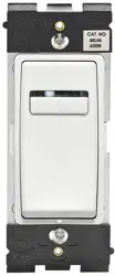
Fluorescent and LED Fixture Slide Dimmer
Single Pole (One location) or 3-Way (Multi-location)
Cat. No. IP710-DL, IP710-D
1200VA-120VAC, 60Hz, 1500VA-277VAC, 60Hz
28mA Maximum Sink Current
For Use with LED fixtures using 0-10V dimmable power supply/drivers, Advance Transformer Mark 7
®
OSRAM Sylvania Quicktronic
®
Helios™ or equivalent dimmable ballasts.
INSTALLATION INSTRUCTIONS
DI-000-IP710-02G
Tools needed to install your Dimmer
Slotted/Philips Screwdriver Electrical Tape Pliers
Pencil Cutters Ruler
Installing Dimmer by itself or with other devices
If installing Dimmer in a single device application, proceed
with the INSTALLING YOUR DIMMER section. If installing
Dimmer in a multi-device application, proceed as follows:
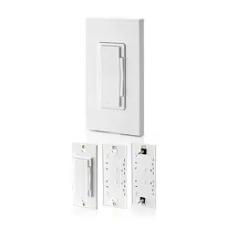
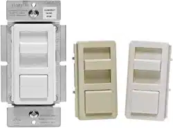
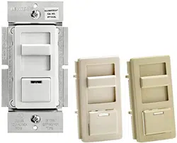
Your Dimmer includes three color options. The Dimmer
ships with the White frame attached. To change color of
frame, proceed as follows:
Changing the color of your Dimmer
Push in side at tab
to release
Line up tabs and
press in side to attach
Note: Move slider on dimmer and slider on change kit
to bottom of the slide bar prior to engaging.
MULTI-DEVICE APPLICATION:
NOTE: You only need to remove side sections if installing
with other dimmers or if it does not fit in wall box – not
when installing with mechanical switches.
When installing more than one dimmer in the same
location, the side sections of the mounting strap must be
removed. Use pliers to carefully bend side sections back
and forth until they break off.
Bend back and
forth to remove side
section
Remove
all inner
side
sections
Do not
remove
outer
side
sections
WARNING: TO AVOID FIRE, SHOCK, OR
DEATH; TURN OFF POWER at circuit breaker or
fuse and test that power is off before wiring!
ONOFF
ONOFF
ONOFF
ONOFF
ONOFF
ONOFF
ONOFFONOFF
ONOFF
ONOFF
ONOFF
ONOFF
Step 1
Note: No derating is required in this mult-device installation
as referenced in the following chart.
MAXIMUM BULB WATTAGE:
0-10VDC ballasts are rated in Volt-Amps (VA). The maximum
number of ballast per dimmer is based on the load VA rating.
The maximum bulb wattage is determined by the efficiency of
the ballast.
NOTE: For additional switching capacity, use dimmers in
conjuction with a Leviton OPP20 120/277V Power Pack.
For applications using Leviton's OPP20 Power Pack
(Shown in Wiring Diagrams 2), the OPP20 switch ratings
are as follows (refer to OPP20 Instruction Sheet for
additional information):
OPP20 SWITCH RATINGS:
20 Amps for 120 and 277 VAC Ballast
0-10 VDC Sink Current Rating:
28 mA maximum sink current. Contact your ballast
manufacturer for the sink current rating of the ballast.
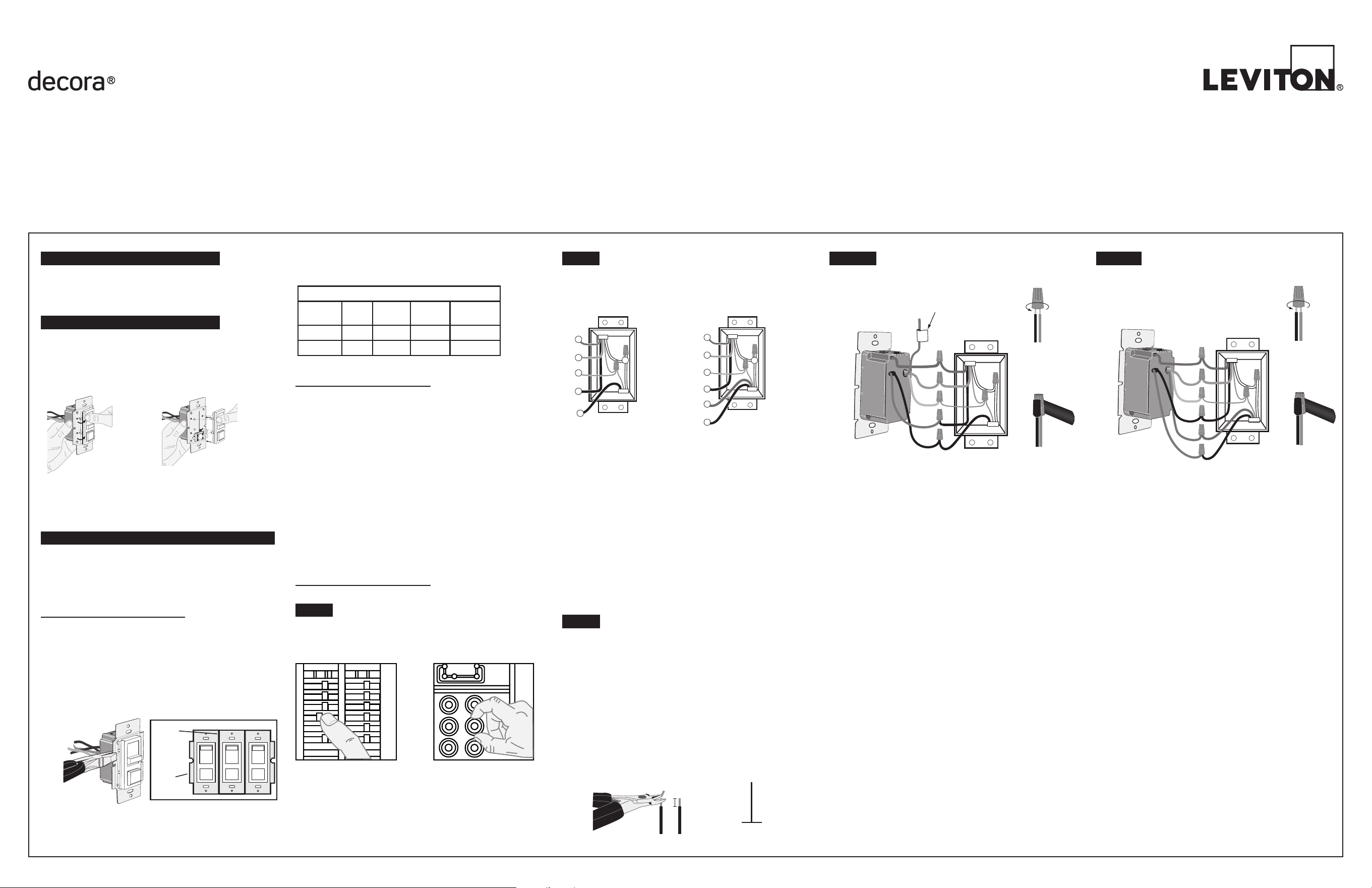
INSTALLING YOUR DIMMER
Step 4A
Step 3
Preparing wires:
• Pull off pre-cut insulation from Dimmer leads.
• Make sure that the ends of the wires from the wall
box are straight (cut if necessary).
• Remove 5/8" (1.6 cm) of insulation from each wire
in the wall box (shown).
• For Single-Pole Application, go to Step 4A.
• For 3-Way Application, go to Step 4B.
Strip Gage
5/8"
(1.6 cm)
Cut
(if necessary)
Strip 5/8"
(1.6 cm)
Insert wires
straight then twist
clockwise
Electrical
Tape
Neutral
Ground
Black
Red
Gray
Violet
Green
Red
This wire is used in 3-way installations only.
For single pole installations, do not remove this
insulating label.
Single-Pole Wiring Application:
• Green dimmer Ground lead to Green or bare copper
wire in wall box.
• Black dimmer lead to Line Hot wall box wire.
• Red dimmer lead without insulating label to Load wall
box wire.
• Remaining Red dimmer lead should have Red
insulation label affixed.
NOTE: If insulating label is not affixed to Red lead, use
a small wire nut or electrical tape to cap off.
• Violet dimmer lead to (+) Violet connection on ballast.
• Gray dimmer lead to (-) Gray connection on ballast.
• Proceed to Step 5.
Connect wires per WIRING DIAGRAM 1
(shown on page 2) as follows:
Screw wire nuts on clockwise making sure no bare
conductors show below the wire connectors. Secure
each connector with electrical tape.
NOTE: Ensure that low-voltage wiring (for Gray and
Violet connection of dimmer) is installed at wallbox
that will house the IP710 Dimmer.
Step 4B
Neutral
Ground
Black
Red
Gray
Violet
Green
Red
• Green dimmer Ground lead to Green or bare copper
wire in wall box.
• Black dimmer lead to tagged (common) wall box
wire identified in step 2.
• Remove Red insulating label from Red lead.
• First Traveler wall box wire identified in step 2 to
any red dimmer lead.
• Second Traveler wall box wire identified in step 2
to the remaining red dimmer lead.
• Violet dimmer lead to (+) Violet connection on
ballast.
• Gray dimmer lead to (-) Gray connection on
ballast.
• Proceed to Step 5.
3-Way Wiring Application:
Connect wires per WIRING DIAGRAM 3
(shown on page 2) as follows:
Screw wire nuts on clockwise making sure no bare
conductors show below the wire connectors. Secure
each connector with electrical tape.
NOTE: Dimmer can be installed on either the Load
or Line side.
NOTE: Ensure that low-voltage wiring (for Gray and
Violet connection of dimmer) is installed at wallbox
that will house the IP710 Dimmer.
NOTE: For additional switching capacity, use
dimmers in conjuction with a Leviton OPP20
120/277V Power Pack.
Insert wires
straight then twist
clockwise
Electrical
Tape
NOTE: For additional switching capacity, use dimmers
in conjuction with a Leviton OPP20 120/277V Power
Pack.
NOTE: Ensure that low-voltage wiring (for Gray and
Violet connection of dimmer) is installed at wallbox
that will house the IP710 Dimmer.
WARNING:
• TO AVOID FIRE, SHOCK, OR DEATH; TURN OFF POWER AT CIRCUIT BREAKER OR FUSE AND TEST THAT POWER IS OFF BEFORE WIRING
OR SERVICING FIXTURE!
CAUTIONS:
• To avoid overheating and possible damage to this device and other equipment, use only with the appropriate LED 0-10V dimmable power supplies/
drivers, Advance Transformer 120/277V Mark 7
®
0-10V ballasts or OSRAM Sylvania Quicktronic
®
Helios™ electronic ballasts.
CAUTIONS:
• To be installed and/or used in accordance with appropriate electrical codes and regulations.
• If you are unsure about any part of these instructions, consult an electrician.
• Lighting fixture and dimmer must be grounded.
• Use this device only with copper or copper clad wire.
NOTE: Use only one (1) dimmer in a 3- or 4-way circuit. The switch(es) will turn the light on at the brightness level selected at the dimmer.
Single Pole
1. Load
2. Neutral
3. Ground
4. Line (Hot)
5. Gray (-)
6. Violet (+)
3-Way
1. Load (See note below)
2. Neutral
3. Ground
4. First Traveler – note color
5. Second Traveler – note color
6. Gray (-)
7. Violet (+)
3
2
1
6
7
4
5
3
1
4
5
6
2
MAXIMUM LOAD PER DIMMER FOR MULTI-DEVICE
Cat. No. Volts Single
Two
Gang
More than
2 Devices
IP710 120 1200VA 1200VA 1200VA
IP710 277 1500VA 1500VA 1500VA
© 2018 Leviton Mfg. Co., Inc.
For additional information, contact Leviton’s Techline at
1-800-824-3005 or visit Leviton’s website at www.leviton.com
© 2018 Leviton Manufacturing Co., Inc.
All Rights Including Trade Dress Rights Reserved
Step 7
Step 5
Restore Power:
Restore power at circuit breaker or fuse.
Installation is complete.
• Restore power at circuit
breaker or fuse.
• Carefully holding Dimmer
as shown, move slider
control lever to highest
position. Lights should
turn ON to brightest level.
If lights do not turn ON,
depress push-button switch
once. Lights should turn
ON to brightest level.
If lights still do not
turn ON, refer to the
TROUBLESHOOTING
section.
Installation may now be
completed by carefully
positioning all wires to
provide room in wall box for
dimmer. Mount dimmer into
box with mounting screws
supplied. Attach wallplate.
Testing your Dimmer prior to mounting in
wall box:
Step 6
Dimmer Mounting:
TURN OFF POWER AT CIRCUIT BREAKER
OR FUSE.
OPERATION
TROUBLESHOOTING
WIRE CONNECTOR / # OF COND.
COMBINATION CHART
1- #12 w/ 1 to 3 #14, #16 or #18
2- #12 w/ 1 or 2 #16 or #18
1- #14 w/ 1 to 4 #16 or #18
2- #14 w/ 1 to 3 #16 or #18
For non-standard wiring
applications, refer to Wire
Nut and Connector Size Chart
• Lights Flickering
- Lamp has a bad connection.
- Wires not secured firmly with wire connectors.
• Light does not turn ON
- Circuit breaker or fuse has tripped.
- Lamp is burned out.
- Lamp Neutral connection is not wired.
NOTE: If further information is needed in identifying
the HOT wire in a 3-Way application, go to Leviton's
website at www.leviton.com.
ON/OFF:
Depress push-button switch to
ON position - Lights will turn ON.
Depress push-button switch to
OFF position - Lights will turn
OFF.
BRIGHTEN & DIM:
Move slider control lever -
Lights will BRIGHTEN or DIM.
NOTE: If using the dimmer in a 3-way application, the
lights will turn ON at brightness set on dimmer's slide
control lever. The lights can be controlled from either
the dimmer or the switch location.
Setting the Maximum Light Level
This dimmer features a Maximum
Trim adjustment to adjust the
maximum light level of the dimmer.
1. Locate the "Trim Adjustment" dial
on the top of the dimmer.
2. Rotate the dial clockwise to
reduce the maximum light level,
or counter-clockwise to increase
the maximum light level.
DI-000-IP710-02G
For Technical Assistance Call: 1-800-824-3005 (U.S.A. Only) www.leviton.com
LIMITED 5 YEAR WARRANTY AND EXCLUSIONS
Leviton warrants to the original consumer purchaser and not for the benefit of anyone else that this product at the time of its sale by Leviton is free of defects in materials and workmanship under normal and proper use for five years from the purchase date. Leviton’s only obligation is to correct such defects by repair or replacement, at its option. For details visit
www.leviton.com or call 1-800-824-3005. This warranty excludes and there is disclaimed liability for labor for removal of this product or reinstallation. This warranty is void if this product is installed improperly or in an improper environment, overloaded, misused, opened, abused, or altered in any manner, or is not used under normal operating conditions or not in
accordance with any labels or instructions. There are no other or implied warranties of any kind, including merchantability and fitness for a particular purpose, but if any implied warranty is required by the applicable jurisdiction, the duration of any such implied warranty, including merchantability and fitness for a particular purpose, is limited to five years.
Leviton is not liable for incidental, indirect, special, or consequential damages, including without limitation, damage to, or loss of use of, any equipment, lost sales or profits or delay or failure to perform this warranty obligation. The remedies provided herein are the exclusive remedies under this warranty, whether based on contract, tort or otherwise.
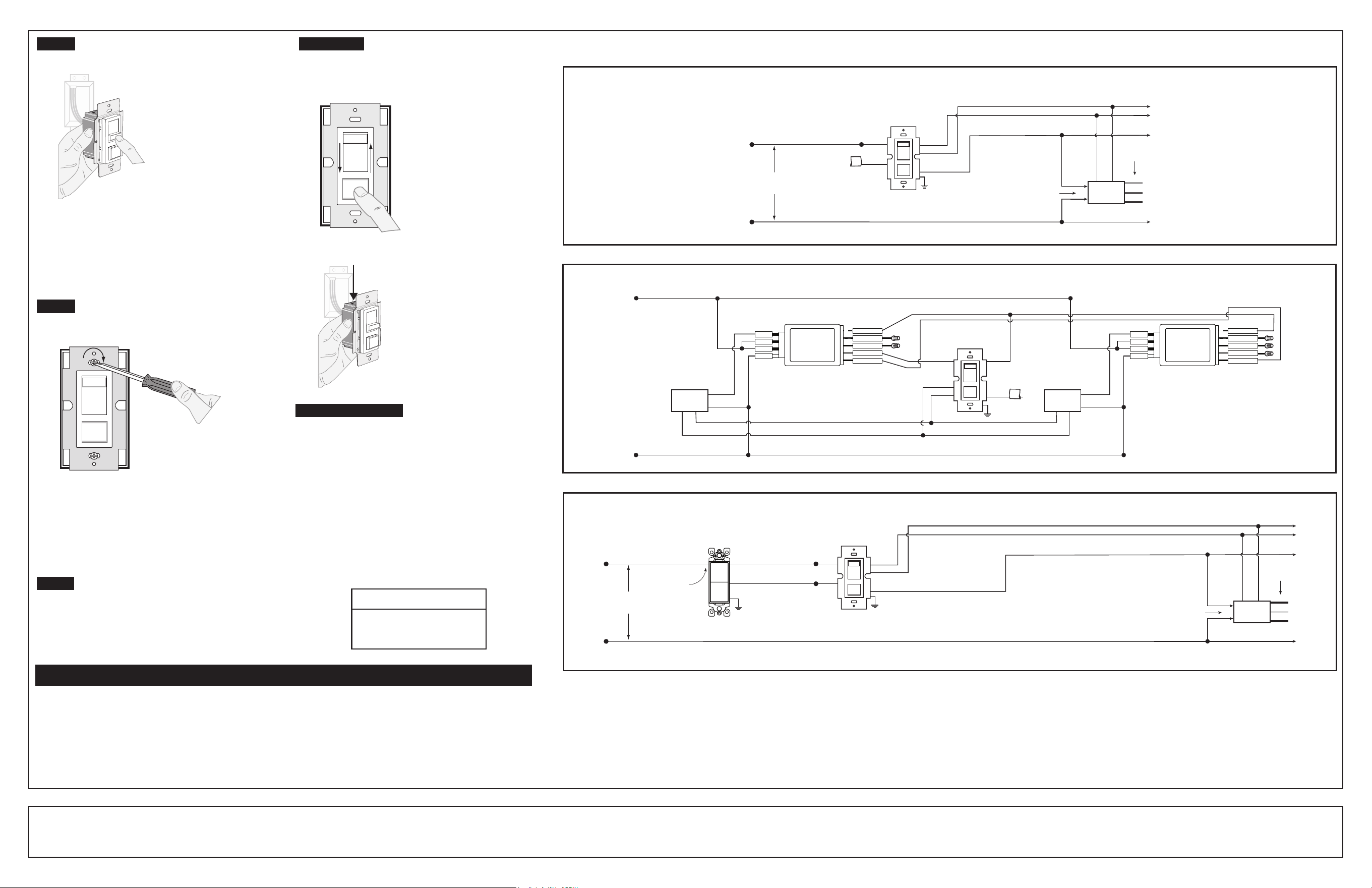
Wiring Diagram 1 : Single Location Control
Hot (Black)
Neutral (White)
To Additional Ballasts
Dimmer
Line
120/277VAC,
60Hz
To Lamps
0-10 VDC
Ballast
Black
White
Yellow
Red
Blue
Primary
Side
Green
Ground
Red
Black
Red
Gray
Violet
Gray
Violet
Insulating
Label
Wiring Diagram 3: Two Location Control
Hot (Black)
Neutral (White)
To Additional Ballasts
Dimmer
Line
120/277VAC,
60Hz
3-Way Switch
To Lamps
Black Screw
(common)
0-10 VDC
Ballast
Black
White
Yellow
Red
Blue
Primary
Side
Green
Ground
Green
Ground
Red
Red
Black
Gray
Violet
Gray
Violet
Third party trademarks are the property of their respective owners
Trim
Adjustment
Dial
Yellow/Orange
Blue
Black
Red
White/Blue
OPP20
Blue
White
Yellow/Orange
Blue
Black
Red
White/Blue
Blue
Black
OPP20
Insulating
Label
Red Black
Violet
Gray
Yellow/Orange
0-10 VDC
Ballast
Black
White
Blue
White
Blue
Black
0-10 VDC
Ballast
Black
White
Gray
Violet
Gray
Violet
Neutral (White)
Hot (Black)
IP710
Dimmer
Wiring Diagram 2 : Single Location Control with OPP20 Power Pack
Red
Green
Ground