WARNINGS AND CAUTIONS:
• Useonlyone(1)dimmerina3-or4-waycircuit.Theswitch(es)willturnthelightonatthe
brightnesslevelselectedatthedimmer.
• UsewithcompatibledimmableLED,CFLbulbs,incandescentor120Vhalogenxturesonly.
ForacompletelistofcompatibleLEDandCFLbulbsrefertowww.leviton.com.
• WhenmultiplebulbsareusedwithonedimmerDO NOTmixbulbtypes.AllbulbsshallbeeitherLED;CFLor
incandescent.Usingthesamemake/modelofeachbulbwillenhancedimmerperformance.
Black
Red
Neutral
Green
Ground
Red
This wire is used in 3-way installations only.
For single pole installations, do not remove
this insulating label.
LED/Compact Fluorescent/Incandescent Slide Dimmer
SinglePole(Onelocation)or3-Way(Multi-location)
Cat.No.IPL06–LED/CFL150W,Incandescent600W
120VAC,60Hz
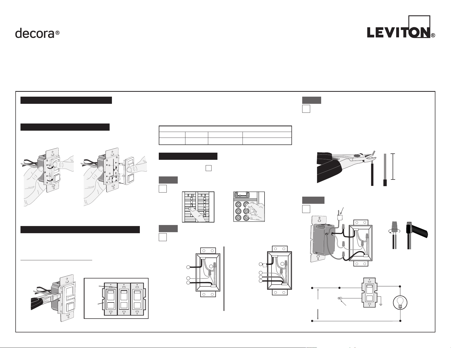
INSTALLATION INSTRUCTIONS
Bend back and forth to remove side section
Tools needed to install your Dimmer
Slotted/PhilipsScrewdriver ElectricalTape
Pliers Pencil
Cutters Ruler
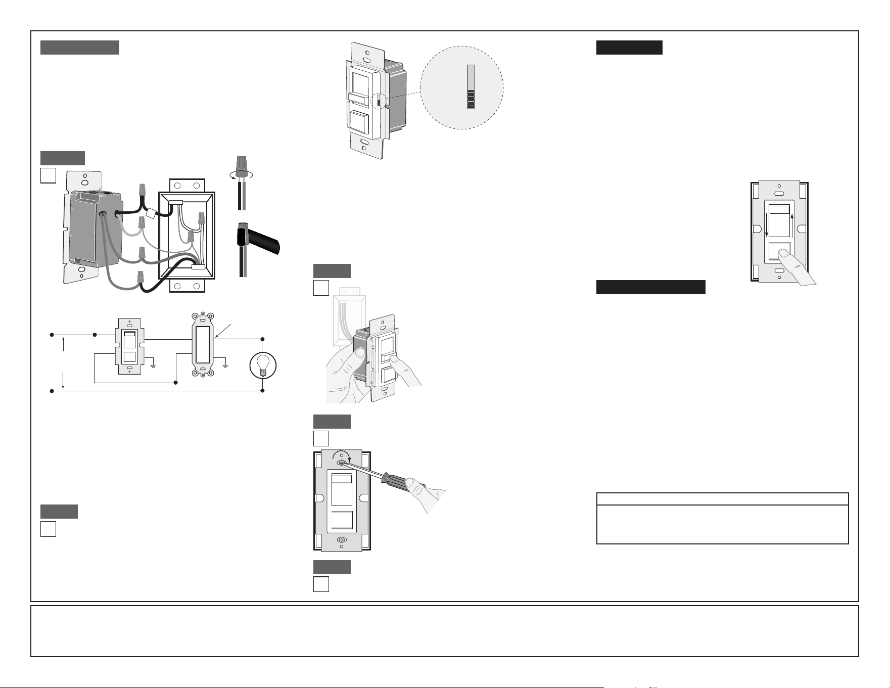
Push in side at tab
to release
Line up tabs on back of
slider to switch shaft and
press in side to attach
Movethesliderupordownonefullcycletoautomaticallyengagethe
slidercontrolmechanism.
Step 3
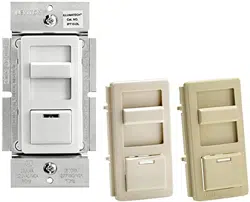
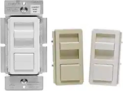
Changing the color of your Dimmer
Ifacolorchangekitisprovidedwithyourdevice,proceedwiththe
followingstepifyouneedtochangethecolor.Otherwise,proceedwith
the"Installing Dimmer by itself or with other devices"section.
Inincandescentmulti-dimmerinstallations,thereductionofthedimmer’s
capacityisrequired.Refertothechartformaximumloadperdimmer.
NoderatingisrequiredforuseinDimmableCFLordimmableLED
multi-dimmerinstallations.
MULTI-DEVICE APPLICATION
NOTE: Youonlyneedtoremovesidesectionsifinstallingwithother
dimmersorifitdoesnottinwallbox–notwheninstallingwith
mechanicalswitches.
Installing Dimmer by itself or with other devices
Wheninstallingmorethanonedimmerinthesamelocation,theside
sectionsofthemountingstrapmustberemoved.Useplierstocarefully
bendsidesectionsbackandforthuntiltheybreakoff.Thesidesections
dissipateheat,soremovingthemrequiresaderatingofthedimmer's
capacity(refer to chart).
Step 2
MAXIMUM LOAD PER DIMMER FOR MULTI-DEVICE
Cat. No.
IPL
Ø
6
Single
600W
Two Devices
500W
More than 2 Devices
400W
ONOFF
ONOFF
ONOFF
ONOFF
ONOFF
ONOFF
ONOFFONOFF
ONOFF
ONOFF
ONOFF
ONOFF
WARNING:Toavoidre,shock,ordeath;TURN OFF
POWERatcircuitbreakerorfuseandtestthatpowerisoff
beforewiring!
Step 1
Identifying your wiring application
(most common):
NOTE:Ifthewiringinthewallboxdoesnotresembleanyof
thesecongurations,consultanelectrician.
Single Pole
1. Line(Hot)
2. Neutral
3. Ground
4. Load
IMPORTANT:For3-Wayapplications,notethatoneofthescrewterminals
fromtheoldswitchbeingremovedwillusuallybeadifferentcolor(Black)
orlabeledCommon.Tagthatwirewithelectricaltapeandidentifyasthe
common(LineorLoad)inboththedimmerwallboxand3-waywallbox.
Preparing and connecting wires:
Strip gage
Cut
(if necessary)
5/8"
• Makesurethattheendsofthewiresfromthewallboxarestraight
(cut if necessary).
• Remove5/8"(1.6cm)ofinsulationfromeachwireinthewallbox
(shown).
• For Single-Pole Application, go to Step 4a.
• For 3-Way Application, go to Step 4b.
Single-Pole Wiring Application:
Insertwires
straightthentwist
clockwise
Electrical
Tape
Step 4a
2
3
1
4
2
4
1
5
3
3-Way
1. LineorLoad
(See note below)
2. Neutral
3. Ground
4. FirstTraveler–notecolor
5. SecondTraveler–notecolor
Remove
all inner
side
sections
Do not
remove
outer
side
sections
DI-000-IPL06-02A-X3
Installing your Dimmer
NOTE: UsecheckboxeswhenStepsarecompleted.
√
Hot (Black)
Neutral (White)
Load
Dimmer
Black
Green
Ground
Black
White
Red
Line
120VAC, 60Hz
Red
Cap with
Wire Connector
WARNINGS AND CAUTIONS:
• TO AVOID FIRE, SHOCK, OR DEATH;TURN OFF POWERatcircuitbreakerorfuseandtestthatpowerisoff
beforewiringorservicingxture!
• Tobeinstalledand/orusedinaccordancewithappropriateelectricalcodesandregulations.
• Ifyouareunsureaboutanypartoftheseinstructions,consultanelectrician.
• Toavoidoverheatingandpossibledamagetothisdeviceandotherequipment,DO NOTinstalltocontrola
receptacle,amotor-oratransformer-operatedappliance,oranyotherlightingsourcesthanthosespecied.
• Usethisdevicewith copper or copper clad wire only.
LIMITED 5 YEAR WARRANTY AND EXCLUSIONS
LevitonwarrantstotheoriginalconsumerpurchaserandnotforthebenetofanyoneelsethatthisproductatthetimeofitssalebyLevitonisfreeofdefectsinmaterialsandworkmanshipundernormalandproperuseforveyearsfromthepurchasedate.Leviton’sonly
obligationistocorrectsuchdefectsbyrepairorreplacement,atitsoption,ifwithinsuchveyearperiodtheproductisreturnedprepaid,withproofofpurchasedate,andadescriptionoftheproblemtoLeviton Manufacturing Co., Inc., Att: Quality Assurance Department, 201
North Service Road, Melville, New York 11747.Thiswarrantyexcludesandthereisdisclaimedliabilityforlaborforremovalofthisproductorreinstallation.Thiswarrantyisvoidifthisproductisinstalledimproperlyorinanimproperenvironment,overloaded,misused,opened,
abused,oralteredinanymanner,orisnotusedundernormaloperatingconditionsornotinaccordancewithanylabelsorinstructions.There are no other or implied warranties of any kind, including merchantability and fitness for a particular purpose,butifanyimplied
warrantyisrequiredbytheapplicablejurisdiction,thedurationofanysuchimpliedwarranty,includingmerchantabilityandtnessforaparticularpurpose,islimitedtoveyears.Leviton is not liable for incidental, indirect, special, or consequential damages, including
without limitation, damage to, or loss of use of, any equipment, lost sales or profits or delay or failure to perform this warranty obligation.Theremediesprovidedhereinaretheexclusiveremediesunderthiswarranty,whetherbasedoncontract,tortorotherwise.
©2011LevitonMfg.Co.,Inc
Connect wires per WIRING DIAGRAM as follows:
Screwwirenutsonclockwisemakingsurenobareconductorsshow
belowthewireconnectors.Secureeachconnectorwithelectricaltape.
• GreendimmerGroundleadtoGreenorbarecopperwireinwallbox.
• Blackdimmerleadtotagged(common)wallboxwireidentiedwhen
removingoldswitch.
• RemoveRedinsulatinglabelfromRedlead.
• AnyReddimmerleadtoanyoftheremainingwallboxwires.
• RemainingReddimmerleadtoremainingwallboxwire.
Restore Power:
Restorepoweratcircuitbreakerorfuse.
Installation is complete.
Step 8
For Technical Assistance Call: 1-800-824-3005 (U.S.A. Only)
www.leviton.com
WIRE CONNECTOR / # OF COND. COMBINATION CHART
1-#12w/1to3#14,#16or#18
2-#12w/1or2#16or#18
1-#14w/1to4#16or#18
2-#14w/1to3#16or#18
For non-standard wiring applications, refer
to Wire Connector and Conductor Size Chart
OPERATION
• Lightsickering
- Lamphasbadconnection.
- Wiresnotsecuredrmlywithwireconnectors.
• CFLandLEDickersatlowendofdimmingrange
- Increasethelowendofthedimmingrange.
Operation Section -settingminimumlightlevel
• CFLorLEDbulbickersthroughoutdimmingrange
- PleaserefertorecommendeddimmableLEDbulbsandCFLbulbs
atwww.leviton.com.
• Light does not turn ON
- Circuitbreakerorfusehastripped.
- Lampisburnedout.
- LampNeutralconnectionisnotwired.
NOTE: If further information is needed in identifying the HOT wire
in a 3-Way application, go to Leviton's website at www.leviton.com.
TROUBLESHOOTING
Step 4a cont'd
Connect wires per WIRING DIAGRAM as follows:
Screwwirenutsonclockwisemakingsurenobareconductorsshow
belowthewireconnectors.Secureeachconnectorwithelectricaltape.
• GreendimmerGroundleadtoGreenorbarecopperwireinwallbox.
• Blackdimmerleadtoanywallboxwireremovedfromoldswitch.
• Reddimmerleadwithoutinsulatinglabeltoremainingwallboxwire.
• RemainingReddimmerleadshouldhaveRedinsulationlabelafxed.
NOTE:IfinsulatinglabelisnotafxedtoRedlead,useasmallwire
nutorelectricaltapetocapoff.Proceed to Step 5.
3-Way Wiring Application:
Insertwires
straightthen
twistclockwise
Electrical
Tape
Step 4b
Hot (Black)
Neutral (White)
Load
Dimmer
3-Way Switch
Red
Black
Green
Ground
Green
Ground
Black
White
Red
Line
120VAC, 60Hz
Common
Terminal
(Black Screw)
Black
Tag
Red
Green
Red
Neutral
Ground
Dimmer Mounting:
TURN OFF POWER AT CIRCUIT BREAKER OR FUSE.
Step 7
Installationmaynowbe
completedbycarefully
positioningallwires
toprovideroomin
wallboxfordimmer.
Mountdimmerintobox
withmountingscrews
supplied.Attachwallplate.
ON/OFF:
Depresspush-buttonswitchtoON
position-LightswillturnON.
Depresspush-buttonswitchtoOFF
position-LightswillturnOFF.
BRIGHTEN & DIM:
Moveslidercontrollever-Lightswill
BRIGHTENorDIM.
DI-000-IPL06-02A-X3
• Restorepoweratcircuitbreaker
orfuse.
• Carefullyholdingdimmeras
shown,moveslidercontrollever
tohighestposition.Lightsshould
turnONtobrightestlevel.Iflights
doesnotturnON,depresspush-
buttonswitchonce.Lightsshould
turnONtobrightestlevel.
If lights still do not
turn ON, refer to the
TROUBLESHOOTING section.
Testing your Dimmer prior to mounting in
wall box:
Step 6
Step 5
Dimmer Bulb Selector Switch:
Cat. No. IPL06ispre-setatthefactorywiththebulb
selectorswitchsettoLED/Incandescent.ForCFLbulb
applicationstheswitchshouldbemovedtotheposition
markedCFL.Thelampselectorslideswitchalsoallows
theusertoadjusttheminimumlightlevelwhendimming.
InformationonthisfeatureisfoundunderOPERATION.
NOTE: Bulbselectorswitchislocatedontherightsideof
thedimmer.See following illustration.
Setting Minimum Light Level (Programming mode)
1. EnsurethedimmerissettotheOFFposition.
2. SetthebulbselectorswitchtotheLED/Incandescentposition.
3. PushrockerswitchtoONposition.
4. SetthebulbselectorswitchtotheCFLposition.
5. Raiseorlowertheslidecontrolleveltoachievethedesiredminimum
lightlevel.
6. SetthebulbselectorswitchbacktoLED/Incandescentposition.
7. Amomentaryashofthebulbwilloccurconrmingthenewsetting.
8. PushrockerswitchtotheOFFposition.
9. FordimmableCFLlampsyoumustreturnthebulbselectortothe
CFLposition.
LED/Incandescent Mode:Theselectorswitchispre-setatthefactory
tothismode.UsethismodefordimmableLEDbulbsandincandescent/
halogenbulbs.Toavoidickeringatthelowendofthedimmingrangeyou
canpre-settheminimumlightlevel.SeeOPERATIONtomanuallyprogram
theminimumlightlevel.
CFL Mode:
TobeusedfordimmableCFLbulbsonly.Inthismodethedimmer
providesapre-setkick-starttoaidthelampinstarting.Toavoidickeringat
thelowendofthedimmingrangeyoucanpre-settheminimumlightlevel.
See
OPERATION
tomanuallyprogramtheminimumlightlevel.
CFL
LED/INC
Bulb Selector
Switch