

AMPLIFIERS
R150X2 R250X1
R250X4 R300X4 R400-4D
R500X1D R600-4D R600X5
R750-1D R1200-1D
Installation & Operation
2
Dear Customer,
Congratulations on your purchase of the world’s finest brand of car audio
products. At Rockford Fosgate we are fanatics about musical reproduc-
tion at its best, and we are pleased you chose our product. Through
years of engineering expertise, hand craftsmanship and critical testing
procedures, we have created a wide range of products that reproduce
music with all the clarity and richness you deserve.
For maximum performance we recommend you have your new Rockford
Fosgate product installed by an Authorized Rockford Fosgate Dealer,
as we provide specialized training through Rockford Technical Training
Institute (RTTI). Please read your warranty and retain your receipt and
original carton for possible future use.
Great product and competent installations are only a piece of the puzzle
when it comes to your system. Make sure that your installer is using
100% authentic installation accessories from Rockford Fosgate in your
installation. Rockford Fosgate has everything from RCA cables and
speaker wire to power wire and battery connectors. Insist on it! After all,
your new system deserves nothing but the best.
To add the finishing touch to your new Rockford Fosgate image order
your Rockford accessories, which include everything from T-shirts to
jackets.
Visit our web site for the latest information on all Rockford products
;
www.rockfordfosgate.com
or, in the U.S. call 1-800-669-9899 or FAX 1-800-398-3985. For all other
countries, call +001-480-967-3565 or FAX +001-480-966-3983.
Table of Content
If, after reading your manual, you still have questions regarding this prod-
uct, we recommend that you see your Rockford Fosgate dealer. If you need
further assistance, you can call us direct at 1-800-669-9899. Be sure to
have your serial number, model number and date of purchase available
when you call.
Safety
This symbol with “WARNING” is intended to
alert the user to the presence of important in-
structions. Failure to heed the instructions will
result in severe injury or death.
This symbol with “CAUTION” is intended to
alert the user to the presence of important in-
structions. Failure to heed the instructions can
result in injury or unit damage.
To prevent injury and damage to the unit, please read and follow the
instructions in this manual. We want you to enjoy this system, not get
a headache.
If you feel unsure about installing this system yourself, have it installed
by a qualified Rockford Fosgate technician.
Before installation, disconnect the battery negative (-) terminal to
prevent damage to the unit, fire and/or possible injury.
Introduction
©2013 Rockford Corporation. All Rights Reserved. ROCKFORD FOSGATE, PUNCH, and associated logos where applicable are registered trademarks of Rockford
Corporation in the United States and/or other countries. All other trademarks are the property of their respective owners. Specifications subject to change without notice.
PRACTICE SAFE SOUND
Continuous exposure to sound pressure levels over 100dB may cause
permanent hearing loss. High powered auto sound systems may
produce sound pressure levels well over 130dB. Use common sense
and practice safe sound.
PRATIQUEZ UNE ÉCOUTE SANS RISQUES
Une exposition continue à des niveaux de pression acoustique upérieurs à
100 dB peut causer une perte d’acuité auditive permanente. Les systè mes
audio de forte puissance pour auto peuvent produire des niveaux de
pression acoustique bien au-delà de 130 dB. Faites preuve de bon sens et
pratiquez une écoute sans risques
PRACTIQUE EL SONIDO SEGURO
El contacto continuo con niveles de presió n de sonido superiores a 100
dB puede causar la pérdida permanente de la audició n. Los sistemas de
sonido de alta potencia para automó viles pueden producir niveles de
presió n de sonido superiores a los 130 dB. Aplique el sentido comú n y
practique el sonido seguro.
PRAKTIZIEREN SIE SICHEREN SOUND
Fortgesetzte Gerä uschdruckpegel von ü ber 100 dB kö nnen beim
Menschen zu permanentem Hö rverlust fü hren. Leistungsstarke
Autosoundsysteme kö nnen Geräuschdruckpegel erzeugen, die weit ü ber
130 dB liegen. Bitte wenden Sie gesunden Menschenverstand an und
praktizieren Sie sicheren Sound.
OSSERVATE LE REGOLE DEL SUONO SENZA PERICOLI
La costante esposizione a livelli di pressione acustica al di sopra dei
100dB possono causare la perdita permanente dell’udito. I sistemi
audio ad alta potenza possono produrre livelli di pressione acustica ben
superiori ai 130dB. Si consiglia il buon senso e l’osservanza delle regole
del suono senza pericoli
2 Introduction
3 Specifications
4-5 Design Features
6-16 Installation
Installation Considerations
Mounting Locations
Battery and Charging
Wiring the System
17 Operation
Adjusting Gain
Adjusting Crossover Frequency
Input Switch
Variable Phase
Punch EQ (Variable & Selectable)
Remote Punch Level Control
18 Troubleshooting
19-26 Additional Languages
French
Spanish
German
Italian
28 Limited Warranty Information

3
Specications
CEA 2006
Power ratings on Rockford Fosgate amplifiers conform to CEA-2006 industry standards. These guidelines
mean your amplifier’s output power ratings are REAL POWER numbers, not inflated marketing ratings.
Mode R150X2 R250X4 R300X4 R400-4D R600-4D R600X5 R250X1 R500X1D R750-1D R1200-1D
Rated Power -
Continuous
Power Rating
(RMS) Measured
@ 14.4V
50x2 @ 4 ohms
75x2 @ 2 ohms
150x1 @ 4 ohms*
40x4 @ 4 ohms
60x4 @ 2 ohms
125x2 @ 4 ohms*
50x4 @ 4 ohms
75x4 @ 2 ohms
150x2 @ 4 ohms*
75x4 @ 4 ohms
100x4 @ 2 ohms
200x2 @ 4 ohms*
100x4 @ 4 ohms
150x4 @ 2 ohms
300x2 @ 4 ohms*
50x4 @ 4 ohms
75x4 @ 2 ohms
150x2 @ 4 ohms*
Sub: 200x1 @ 4 ohms
Sub: 300x1 @ 2 ohms
150x1 @ 4 ohms
250x1 @ 2 ohms
300x1 @ 4 ohms
500x1 @ 2 ohms
250x1 @ 4 ohms
500x1 @ 2 ohms
750x1 @ 1 ohm
400x1 @ 4 ohms
800x1 @ 2 ohms
1200x1 @ 1 ohm
Crossover
Slope
12 dB/Oct 12 dB/Oct 12 dB/Oct 12 dB/Oct 12 dB/Oct 12 dB/Oct 12 dB/Oct 12 dB/Oct 12 dB/Oct 12 dB/Oct
Crossover
Frequency
Variable 50Hz-250Hz Variable 50Hz-250Hz Variable 50Hz-250Hz Variable 50Hz-250Hz Variable 50Hz-250Hz Variable 50Hz-250Hz Variable 50Hz-250Hz Variable 50Hz-250Hz Variable 50Hz-250Hz
SS: 15Hz-40Hz
Variable 50Hz-250Hz
SS: 15Hz-40Hz
Punch EQ
Variable 0 -
+
12dB @
45Hz
Selectable 0/
+
6dB/
+
12dB
@ 45Hz
Selectable 0/
+
6dB/
+
12dB
@ 45Hz
Variable 0 -
+
18dB @
45Hz
Variable 0 -
+
18dB @
45Hz
Selectable 0/
+
6dB/
+
12dB
@ 45Hz
Sub: Variable 0 -
+
12dB
@ 45Hz
Variable 0 -
+
12dB @
45Hz
Variable 0 -
+
12dB @
45Hz
Variable 0 -
+
18dB @
45Hz
Variable 0 -
+
18dB @
45Hz
Operating
Voltage
9-16VDC 9-16VDC 9-16VDC 9-16VDC 9-16VDC 9-16VDC 9-16VDC 9-16VDC 9-16VDC 9-16VDC
Frequency
Response
20Hz-20kHz 20Hz-20kHz 20Hz-20kHz 20Hz-20kHz 20Hz-20kHz 20Hz-20kHz 20Hz-250Hz 20Hz-250Hz 20Hz-250Hz 20Hz-250Hz
Battery Fuse
Rating (not
supplied)
20A 50A 50A 50A 100A 80A 30A 50A 100A 150A
THD+N @
Rated Power
<1.0% @ 4 ohms
<1.0% @ 2 ohms
<1.0% @ 4 ohms
<1.0% @ 2 ohms
<1.0% @ 4 ohms
<1.0% @ 2 ohms
<1.0% @ 4 ohms
<1.0% @ 2 ohms
<1.0% @ 4 ohms
<1.0% @ 2 ohms
F/R:
<1.0% @ 4 ohms
<1.0% @ 2 ohms
Sub:
<1.0% @ 4 ohms
<1.0% @ 2 ohms
<1.0% @ 4 ohms
<1.0% @ 2 ohms
<1.0% @ 4 ohms
<1.0% @ 2 ohms
<1.0% @ 4 ohms
<1.0% @ 2 ohms
<1.0% @ 1 ohm
<1.0% @ 4 ohms
<1.0% @ 2 ohms
<1.0% @ 1 ohm
Input Sensitivity
150mV-4V Low Level
450mV-12V High Level
150mV-4V Low Level
450mV-12V High Level
150mV-4V Low Level
450mV-12V High Level
150mV-4V 150mV-4V 150mV-4V Low Level
450mV-12V High Level
150mV-4V Low Level
450mV-12V High Level
150mV-4V Low Level
450mV-12V High Level
150mV-4V 150mV-4V
Input Imped-
ance
20k 20k 20k 20k 20k 20k 20k 20k 20k 20k
S/N Ratio CEA
2006
>80dB >80dB >80dB >70dB >70dB F/R: > 80dB
Sub: >80dB
>80dB >80dB >75dB >75dB
S/N Ratio @
Rated Power
>100dB >100dB >100dB >90dB >90dB F/R: >100dB
Sub: >100dB
>100dB >100dB >100dB >100dB
Channel
Separation
>50dB >50dB >50dB >50dB >50dB >50dB N/A N/A N/A N/A
Common Mode
Rejection Ratio
>40dB >55dB >40dB >55dB >55dB >55dB >40dB >55dB >55dB >55dB
Damping Factor
>200dB >200dB >200dB >200dB >200dB F/R: >200dB
Sub: >200dB
>200dB >200dB >200dB >200dB
Dimensions
(LxWxH)
11.2”
x
6.8”
x
2”
(28.5cm x 17.2cm x 5.1 cm)
11.2”
x
6.8”
x
2”
(28.5cm x 17.2cm x 5.1 cm)
13.2”
x
6.8”
x
2”
(33.5cm x 17.2cm x 5.1 cm)
9.1”
x
6.8”
x
2”
(23.1cm x 17.2cm x 5.1 cm)
11.1”
x
6.8”
x
2”
(28.2cm x 17.2cm x 5.1 cm)
13.2”
x
6.8”
x
2”
(33.5cm x 17.2cm x 5.1 cm)
11.2”
x
6.8”
x
2”
(28.5cm x 17.2cm x 5.1 cm)
8.5”
x
6.8”
x
2”
(21.6cm x 17.2cm x 5.1 cm)
9.1”
x
6.8”
x
2”
(23.1cm x 17.2cm x 5.1 cm)
11.1”
x
6.8”
x
2”
(28.2cm x 17.2cm x 5.1 cm)
* Rated power when amplifier is wired in a bridged configuration.
4
REMGND B+
BRIDGED
++
–
+
–
RIGHTLEFT
REAR
SUB
+
–
PWR/
PRT
PUNCH EQ.
0
dB
+
6
50 250
FREQ. Hz
GAIN
1
3 9
11
5 7
SUB
PUNCH EQ.
MIN MAX
PHASE
0˚-180˚
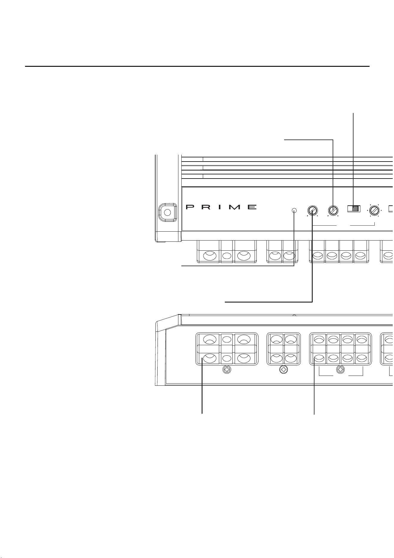
DesignFeatures
Variable Phase
The variable 0-180˚ phase control allows the listener
to change the arrival time of the subwoofer sound
waves relative to the same frequencies from the main
speakers.
Power/Protect LED
Power LED illuminates blue when the unit is turned on. Protect/
Thermal LED illuminates red when amplifier overheats or short
circuits. The amplifier will automatically shut down if this occurs.
Speaker Terminals
The Speaker Terminals are nickel-plated
set-screw wire connectors (+ and -) will
accommodate 8 AWG.
Punch EQ - Variable
This variable control works along with the crossover
switch on the amplifier, boosting the bass frequencies.
Power/REM Terminals
The Power and Ground Terminals are nickel-plat-
ed set-screw wire connectors and will accommo-
date 4 AWG. The REM Terminal is a nickel-plated
set-screw wire connector and will accommodate
8 AWG.
Variable Crossover
A built-in 12dB/octave Butterworth filter with a crossover
point variable from 50Hz to 250Hz. (R750-1D & R1200-1D
have an additional 12dB/octave Infrasonic filter with a cross-
over point variable from 15Hz to 40Hz SS)
5
BRIDGED
–
+
–
RIGHTLEFT
FRONT
L
R
FRONT
HIGH LEVEL
INPUT
FRONTREAR
REARSUB
REMOTE PUNCH LEVEL
L+R+
L
-
R
-
50 250
FREQ. Hz
GAIN
1
3 9
11
5 7
X-OVER
LP - AP - HP
PUNCH EQ.
2/4/5 CH.
SWITCH
FRONT
50 250
FREQ. Hz
GAIN
1
3 9
11
5 7
X-OVER
LP - AP - HP
PUNCH EQ.
6
dB
+
12
dB
0
dB
+
6
dB
+
12
dB
REAR
2 CH. - 4 CH. - 5 CH.
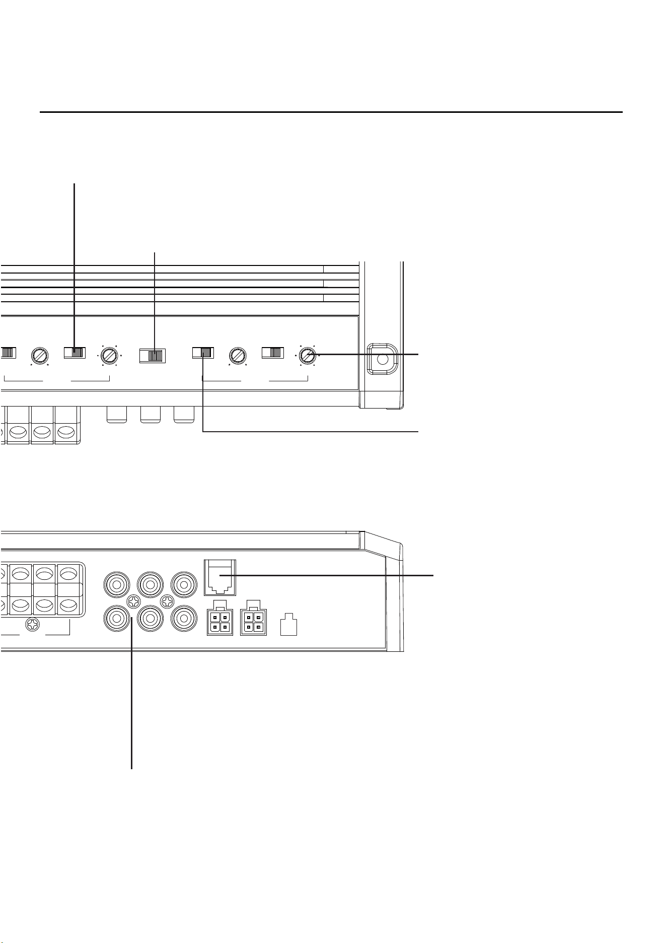
DesignFeatures
illus.-1.1
Gain Control
The gain control is used to match the output of the
audio source.
Punch EQ - Selectable
This selectable control works along with the
crossover switch on the amplifier, boosting the
bass frequencies.
RCA Input/Pass-Thru Jacks
The RCA Inputs/Pass-Thru Jacks are nickel-plated to resist the signal degradation
caused by corrosion. The Pass-Thru provides a convenient source for daisy-chaining
an additional amplifier without running an extra set of RCA cables from the front of the
vehicle to the rear amplifier location.
Input Switch
Setting this switch to the connected inputs aligns the
output signal accordingly or can supplement signal to
additional channels when not connected.
Crossover Switch
Selectable switch for Low-Pass (LP) or
All Pass (AP) or High-Pass (HP)
Remote Punch Level Control
Remotely control the subwoofer output
level of the amplifier.
High Level Inputs - Optional Inputs
Accepts High Level speaker signal when utilizing
the 4-pin Molex harness provided.
6
Contents
Installation Considerations
The following is a list of tools needed for installation:
This section focuses on some of the vehicle considerations for install-
ing your new amplifier. Pre-planning your system layout and best wiring
routes will save installation time. When deciding on the layout of your new
system, be sure that each component will be easily accessible for making
adjustments.
If you feel unsure about installing this system yourself, have it installed by
a qualified technician.
Before installation, disconnect the battery neg-
ative (-) terminal to prevent damage to the unit,
fire and/or possible injury.
Before beginning any installation, follow these
simple rules:
1. Be sure to carefully read and understand the instructions before
attempting to install the unit.
2. For safety, disconnect the negative lead from the battery prior to
beginning the installation.
3. For easier assembly, we suggest you run all wires prior to mounting
your unit in place.
4. Route all of the RCA cables close together and away from any high
current wires.
5. Use high quality connectors for a reliable installation and to minimize
signal or power loss.
Fuse-holder and fuse. (See
specifications for fuse rating)
Volt/Ohm Meter
Wire strippers
Wire crimpers
Wire cutters
#2 Phillips screwdriver
Battery post wrench
Hand held drill w/assorted bits
Assorted connectors
Adequate Length—Red
PowerWire
Adequate Length—Remote
Turn-onWire
Adequate Length—Black
GroundingWire
6. Think before you drill! Be careful not to cut or drill into gas tanks, fuel
lines, brake or hydraulic lines, vacuum lines or electrical wiring when
working on any vehicle.
7. Never run wires underneath the vehicle. Running the wires inside the
vehicle provides the best protection.
8. Avoid running wires over or through sharp edges. Use rubber or
plastic grommets to protect any wires routed through metal, especially
the firewall.
9. ALWAYS protect the battery and electrical system from damage with
proper fusing. Install the appropriate fuse holder and fuse on the +12V
power wire within 18” (45.7 cm) of the battery terminal.
10. When grounding to the chassis of the vehicle, scrape all paint from
the metal to ensure a good, clean ground connection. Grounding
connections should be as short as possible and always be connected
to metal that is welded to the main body, or chassis, of the vehicle.
Seatbelt bolts should never be used for connecting to ground.
Mounting Locations
To ensure optimal performance, mount the amplifier with at least
1” (2.54cm) of air gap around the amplifier’s heat sink to provide
proper cooling.
Trunk Mounting
Mounting the amplifier vertically or inverted will provide adequate cool-
ing of the amplifier. Mounting the amplifier on the floor of the trunk will
provide the best cooling of the amplifier.
Passenger Compartment Mounting
Mounting the amplifier in the passenger compartment will work as long as
you provide a sufficient amount of air for the amplifier to cool itself. If you
are going to mount the amplifier under the seat of the vehicle, you must
have at least 1” (2.54cm) of air gap around the amplifier’s heatsink.
Never mount this unit in the engine compart-
ment. Mounting the unit in the engine com-
partment will void your warranty.
Battery and Charging
Amplifiers will put an increased load on the vehicle’s battery and charging
system. We recommend checking your alternator and battery condition
to ensure that the electrical system has enough capacity to handle the
increased load of your stereo system. Stock electrical systems which are
in good condition should be able to handle the extra load of any Prime
Series amplifier without problems, although battery and alternator life can
be reduced slightly. To maximize the performance of your amplifier, we
suggest the use of a heavy duty battery and an energy storage capacitor.
Installation Installation
Prime Amplifier
Mounting Hardware
Allen Wrench
Punch Level Control
4-pin Molex Connector (if
equipped)
Installation & Operation
Manual

7
Installation Installation
Wiring the System
If you do not feel comfortable with wiring your
new unit, please see your local Authorized
Rockford Fosgate Dealer for installation.
Before installation, disconnect the battery neg-
ative (-) terminal to prevent damage to the unit,
fire and/or possible injury.
Avoid running power wires near the low level
input cables, antenna, power leads, sensitive
equipment or harnesses. The power wires car-
ry substantial current and could induce noise
into the audio system.
1. Plan the wire routing. Keep RCA cables close together but isolated
from the amplifier’s power cables and any high power auto accessories,
especially electric motors. This is done to prevent coupling the noise
from radiated electrical fields into the audio signal. When feeding
the wires through the firewall or any metal barrier, protect them with
plastic or rubber grommets to prevent short circuits. Leave the wires
long at this point to adjust for a precise fit at a later time.
2. Prepare the RED wire (power cable) for attachment to the amplifier by
stripping 1/2” of insulation from the end of the wire. Insert the bared
wire into the B+ terminal and tighten the set screw to secure the cable
in place.
NOTE: The B+ cable MUST be fused 18” or less from the vehicle’s battery.
Install the fuseholder under the hood and ensure connections are water
tight.
3. Trim the RED wire (power cable) within 18” of the battery and splice in
a inline fuse holder (not supplied). See Specifications for the rating of
the fuse to be used. DO NOT install the fuse at this time.
4. Strip 1/2” from the battery end of the power cable and crimp an
appropriate size ring terminal to the cable. Use the ring terminal to
connect to the battery positive terminal.
5. Prepare the BLACK wire (Ground cable) for attachment to the amplifier
by stripping 1/2” of insulation from the end of the wire. Insert the bare
wire into the GROUND terminal and tighten the set screw to secure the
cable in place. Prepare the chassis ground by scraping any paint from
the metal surface and thoroughly clean the area of all dirt and grease.
Strip the other end of the wire and attach a ring connector. Fasten the
cable to the chassis using a non-anodized screw and a star washer.
NOTE: Keep the length of the BLACK wire (Ground) as short as possible.
Always less than 30”.
6. Prepare the Remote turn-on wire for attachment to the amplifier by
stripping 1/2” of insulation from the end of the wire. Insert the bared
wire into the REMOTE terminal and tighten the set screw to secure the
wire in place. Connect the other end of the Remote wire to a switched
12 volt positive source. The switched voltage is usually taken from the
source unit’s remote amp on lead. If the source unit does not have this
output available, the recommended solution is to wire a mechanical
switch in line with a 12 volt source to activate the amplifier.
7. Securely mount the amplifier to the vehicle or amp rack. Be careful not
to mount the amplifier on cardboard or plastic panels. Doing so may
enable the screws to pull out from the panel due to road vibration or
sudden vehicle stops.
8. Connect from source signal by plugging the RCA cables into the input
jacks at the amplifier.
NOTE: All “ACTIVE” inputs must have RCA jacks connected. Switch in
2CH. position,“ACTIVE” - Front channel inputs only. Switch in 4CH.
position,“ACTIVE” - All Front and Rear channel inputs. Switch in 5CH
position,“ACTIVE” - Sub inputs for sub output. When connecting to the
5-Channel inputs, be sure to route front, rear and sub RCA cables tightly
together.
Always ensure power is off or disconnected at
the amplifier before connecting RCA cables.
Failure to do so may cause damage to the am-
plifier and/or connected components.
Note: When the installation requires a High Level (Speaker) input, use the
4-pin Molex connector to tie into your vehicles speaker wiring.
9. Connect the speakers. Strip the speaker wires 1/2” and insert into the
speaker terminal and tighten the set screw to secure into place. Be
sure to maintain proper speaker polarity. DO NOT chassis ground any
of the speaker leads as unstable operation may result.
10. Perform a final check of the completed system wiring to ensure that all
connections are accurate. Check all power and ground connections
for frayed wires and loose connections which could cause problems.
Install inline fuse near battery connection.
NOTE: Follow the diagrams for proper signal polarity.
This amplifier is not recommended for im-
pedance loads below 2-Ohm stereo/4-Ohm
bridged for the front/rear channels and 2-ohm
for the sub channel. Models R750-1D and
R1200-1D are not recommended for imped-
ance loads below 1-Ohm.
8
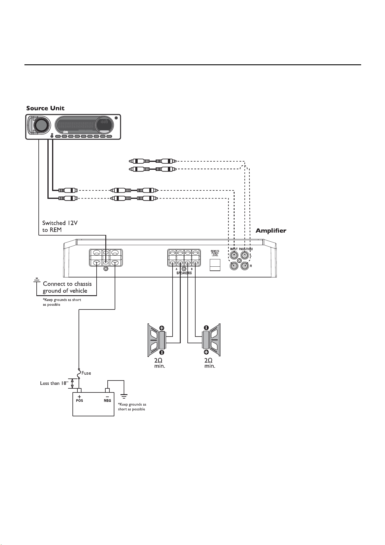
Installation Installation
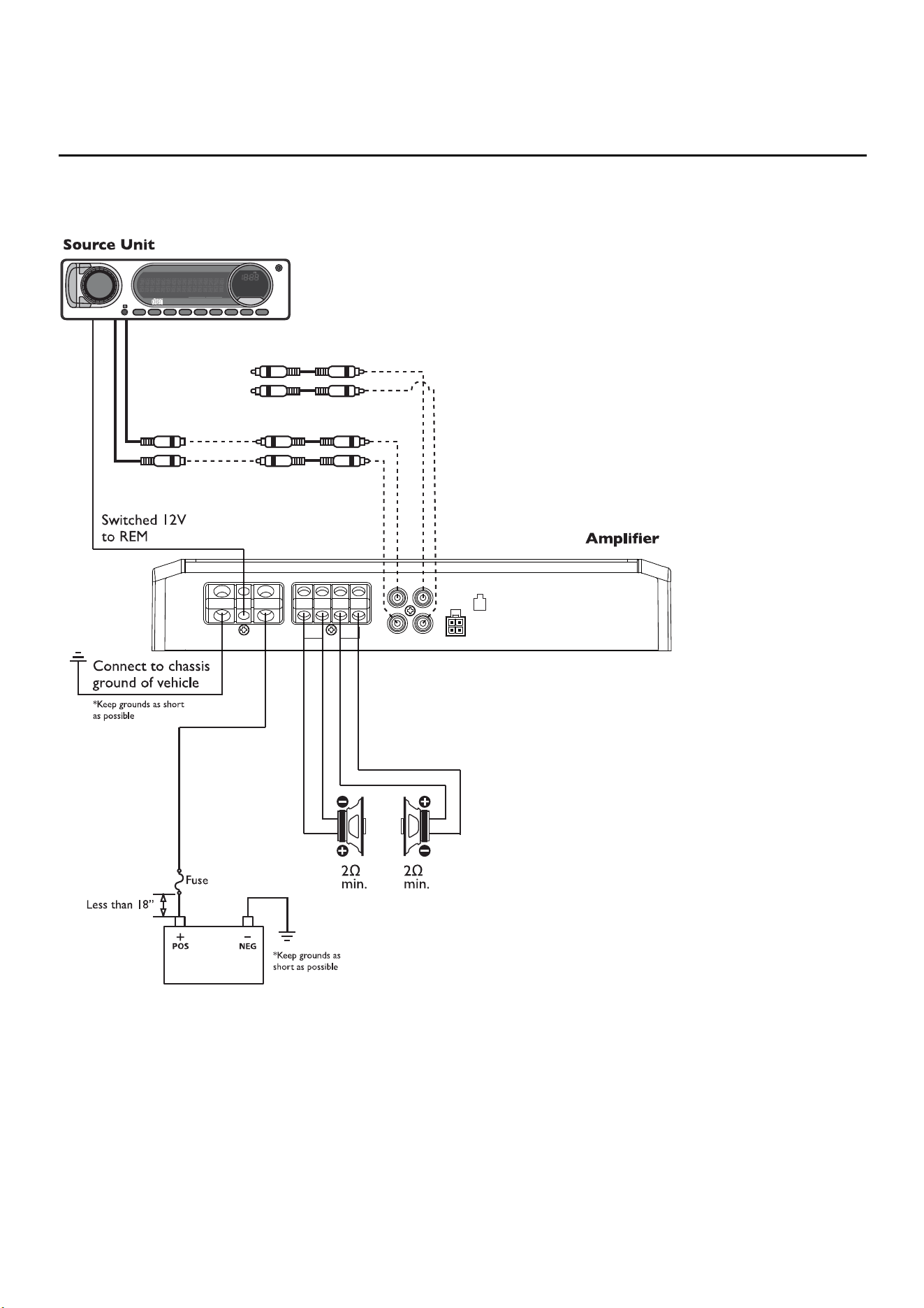
2-Channel (Stereo)
R150X2
illus.-2.1 illus.-2.2
PASS-THRU
Connect to inputs
of 2nd amplifier
*Installation option for
multi-amp install
B+REMGND
L
R
INPUT
+
–
+
–
RIGHTLEFT
BRIDGED
SPE AKERS
HIGH LEVEL
INPUT
L+R+
L
-
R
-
PASS-THRU
9
Installation Installation
2-Channel (Mono)
R150X2
illus.-2.1 illus.-2.2
PASS-THRU
Connect to inputs
of 2nd amplifier
*Installation option for
multi-amp install
B+REMGND
L
R
INPUT
+
–
+
–
RIGHTLEFT
BRIDGED
SPE AKERS
HIGH LEVEL
INPUT
L+R+
L
-
R
-
PASS-THRU
10
Installation Installation
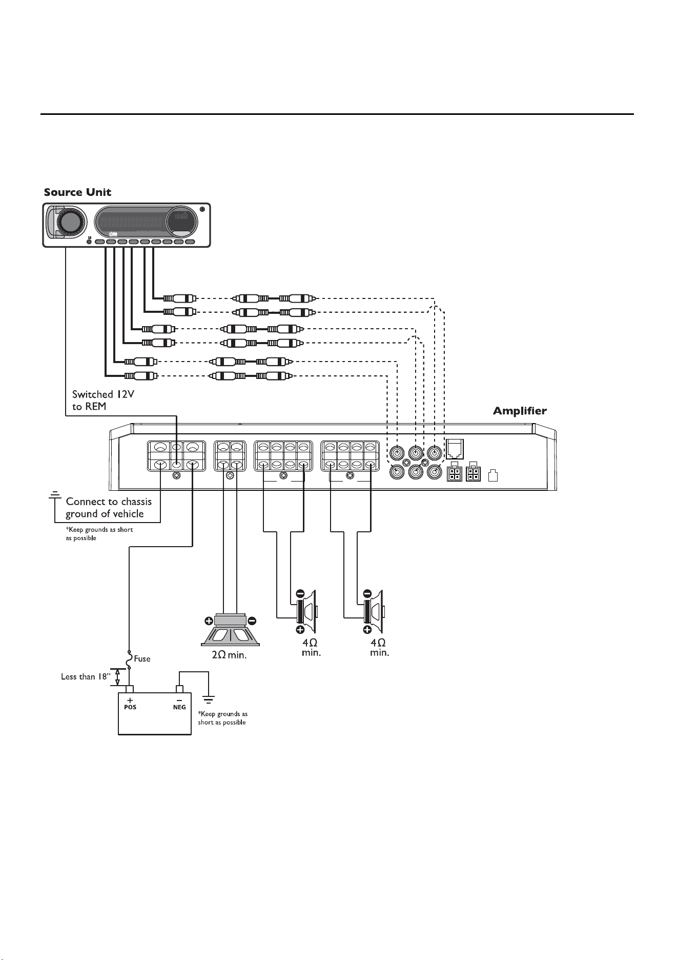
illus.-2.3 illus.-2.4
4-Channel (Stereo)
R250X4, R300X4, R400-4D & R600-4D
REMGND
L
R
FRONT
B+
HIGH LEVEL
INPUT
FRONTREAR
REAR
+
–
+
–
RIGHTLEFT
BRIDGED
REAR
+
–
+
–
RIGHTLEFT
BRIDGED
FRONT
L+R+
L
-
R
-
11
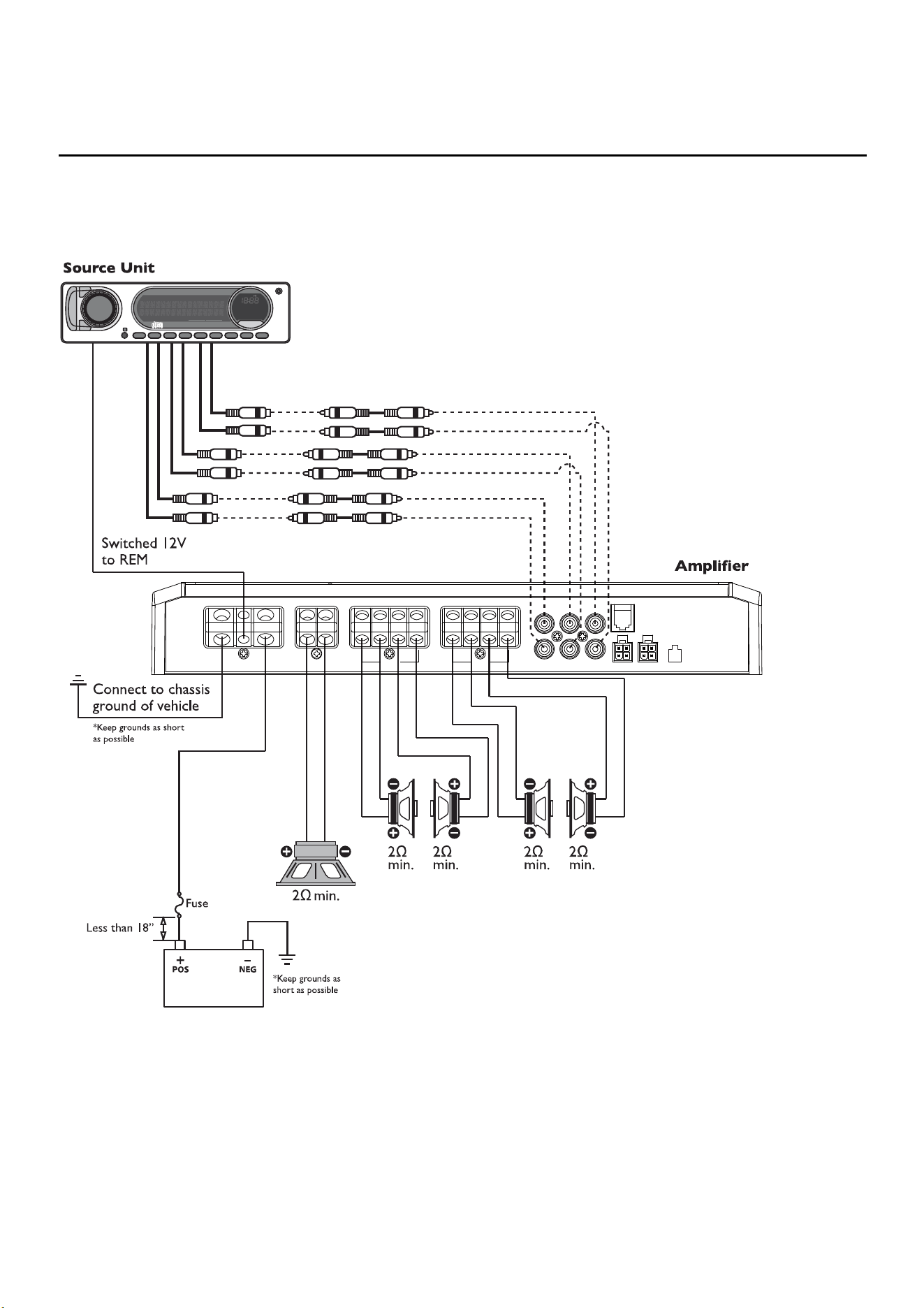
Installation Installation
illus.-2.3 illus.-2.4
4-Channel (2ch Stereo & 1ch Mono-Bridged)
R250X4, R300X4, R400-4D & R600-4D
REMGND
L
R
FRONT
B+
HIGH LEVEL
INPUT
FRONTREAR
REAR
+
–
+
–
RIGHTLEFT
BRIDGED
REAR
+
–
+
–
RIGHTLEFT
BRIDGED
FRONT
L+R+
L
-
R
-

12
Installation Installation
illus.-2.5 illus.-2.6
4-Channel (2ch Mono-Bridged)
R250X4, R300X4, R400-4D & R600-4D
REMGND
L
R
FRONT
B+
HIGH LEVEL
INPUT
FRONTREAR
REAR
+
–
+
–
RIGHTLEFT
BRIDGED
REAR
+
–
+
–
RIGHTLEFT
BRIDGED
FRONT
L+R+
L
-
R
-
13
Installation Installation
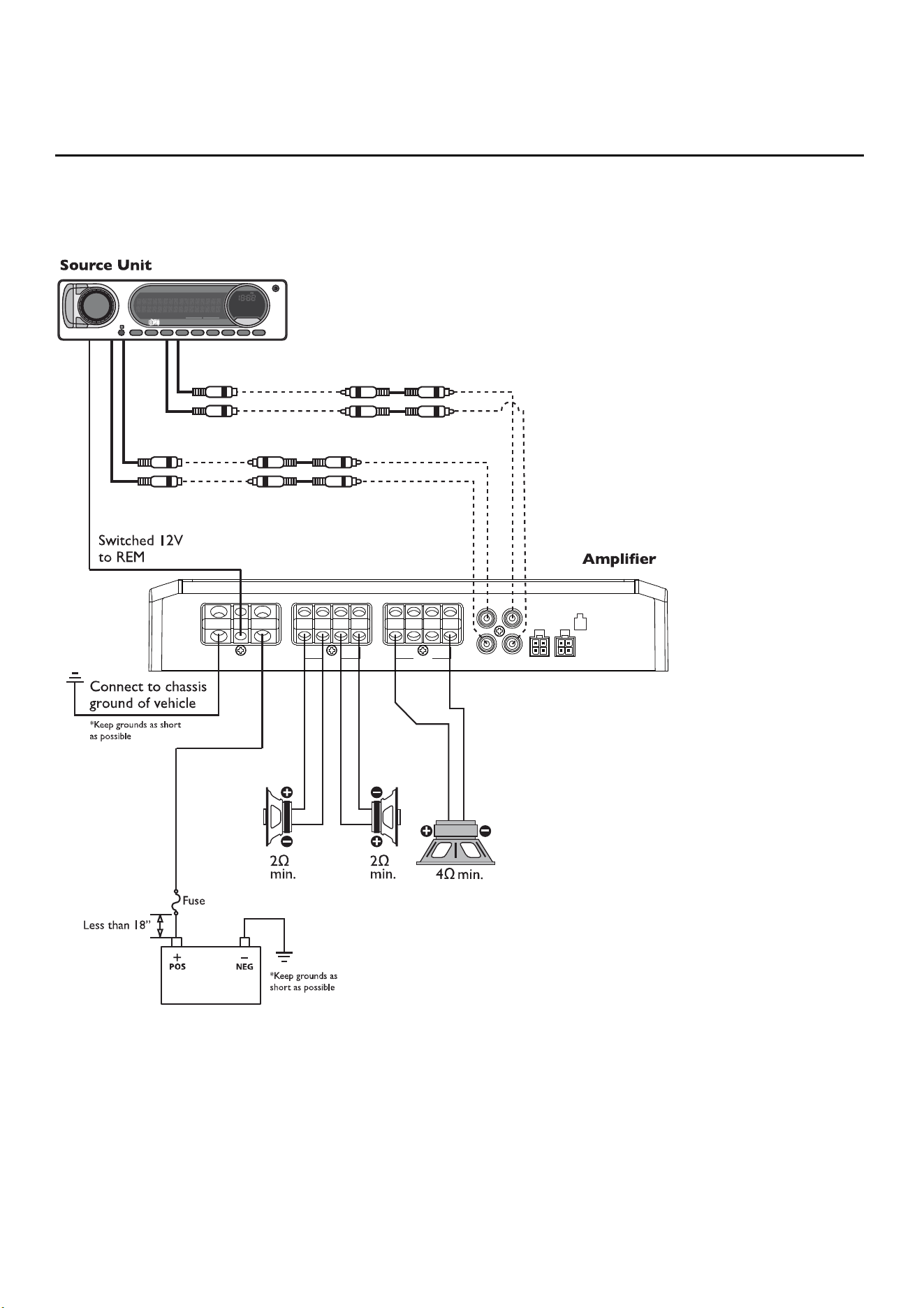
illus.-2.5 illus.-2.6
3-Channel (2ch Bridged & 1ch Parallel)
R600X5
REMGND B+
BRIDGEDBRIDGED
+
–
+
–
RIGHTLEFT
FRONT
+
–
+
–
RIGHTLEFT
REAR
L
R
FRONT
HIGH LEVEL
INP UT
FRONTREAR
REARSUB
REMOTE PUNCH LEVE L
SUB
+
–
L+R+
L
-
R
-
14
Installation Installation
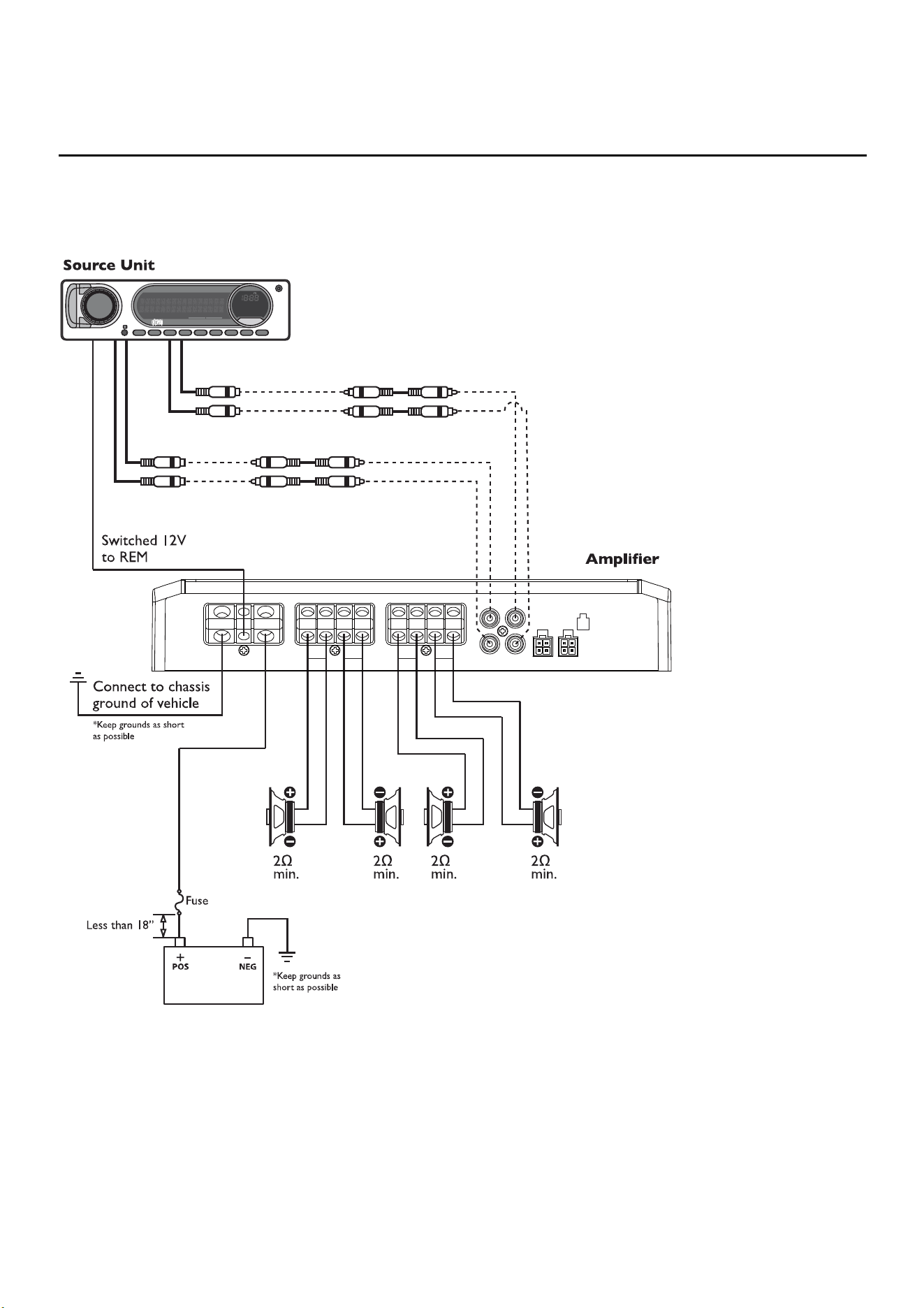
5-Channel (4ch Stereo & 1ch Mono)
R600X5
*Positive(+) and Negative(–) outputs
are wired in parallel internally.
REMGND B+
BRIDGEDBRIDGED
+
–
+
–
RIGHTLEFT
FRONT
+
–
+
–
RIGHTLEFT
REAR
L
R
FRONT
HIGH LEVEL
INPUT
FRONTREAR
REARSUB
REMOTE PUNCH LEVE L
SUB
+
–
L+R+
L
-
R
-
illus.-2.7 illus.-2.8
15
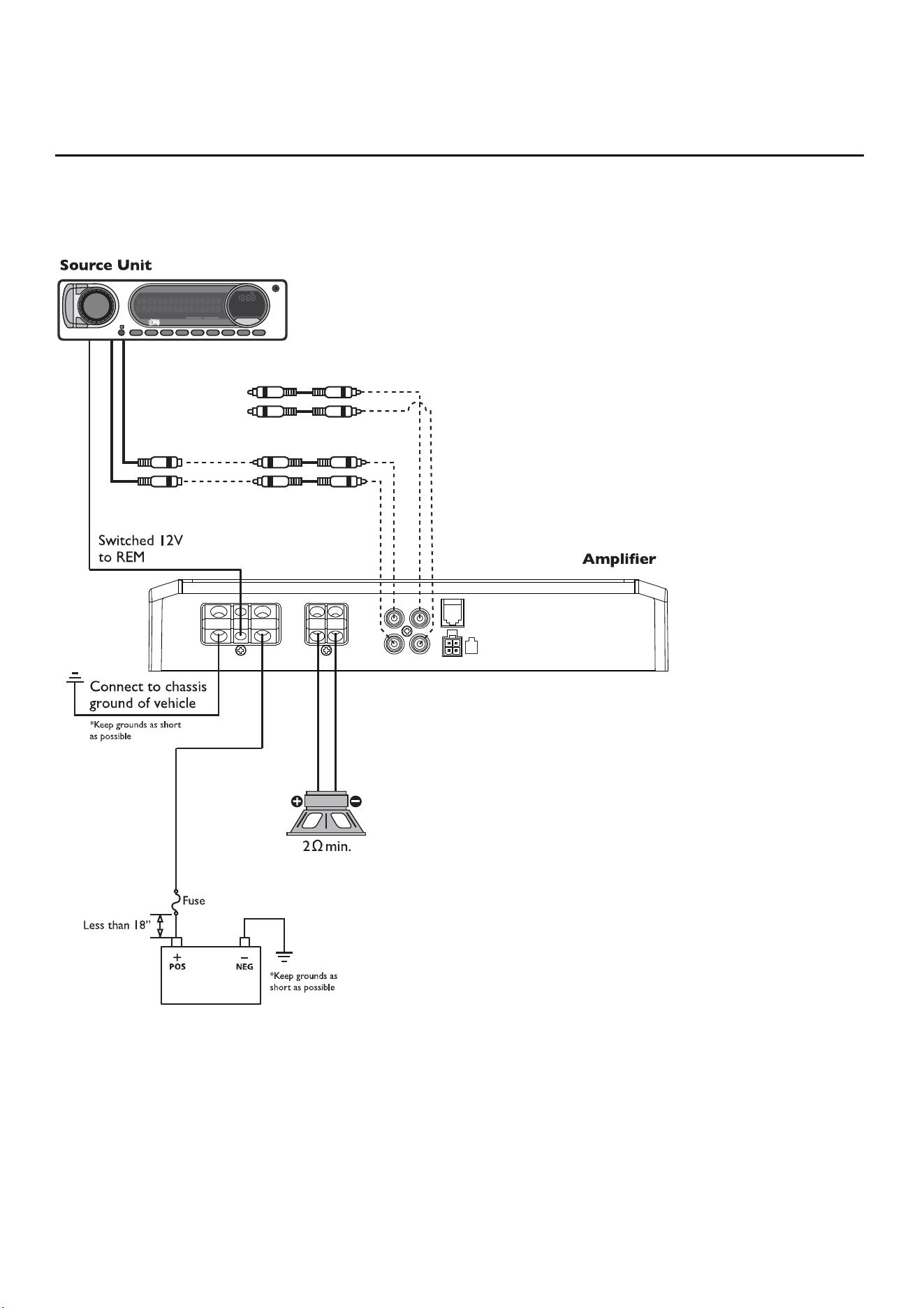
Installation Installation
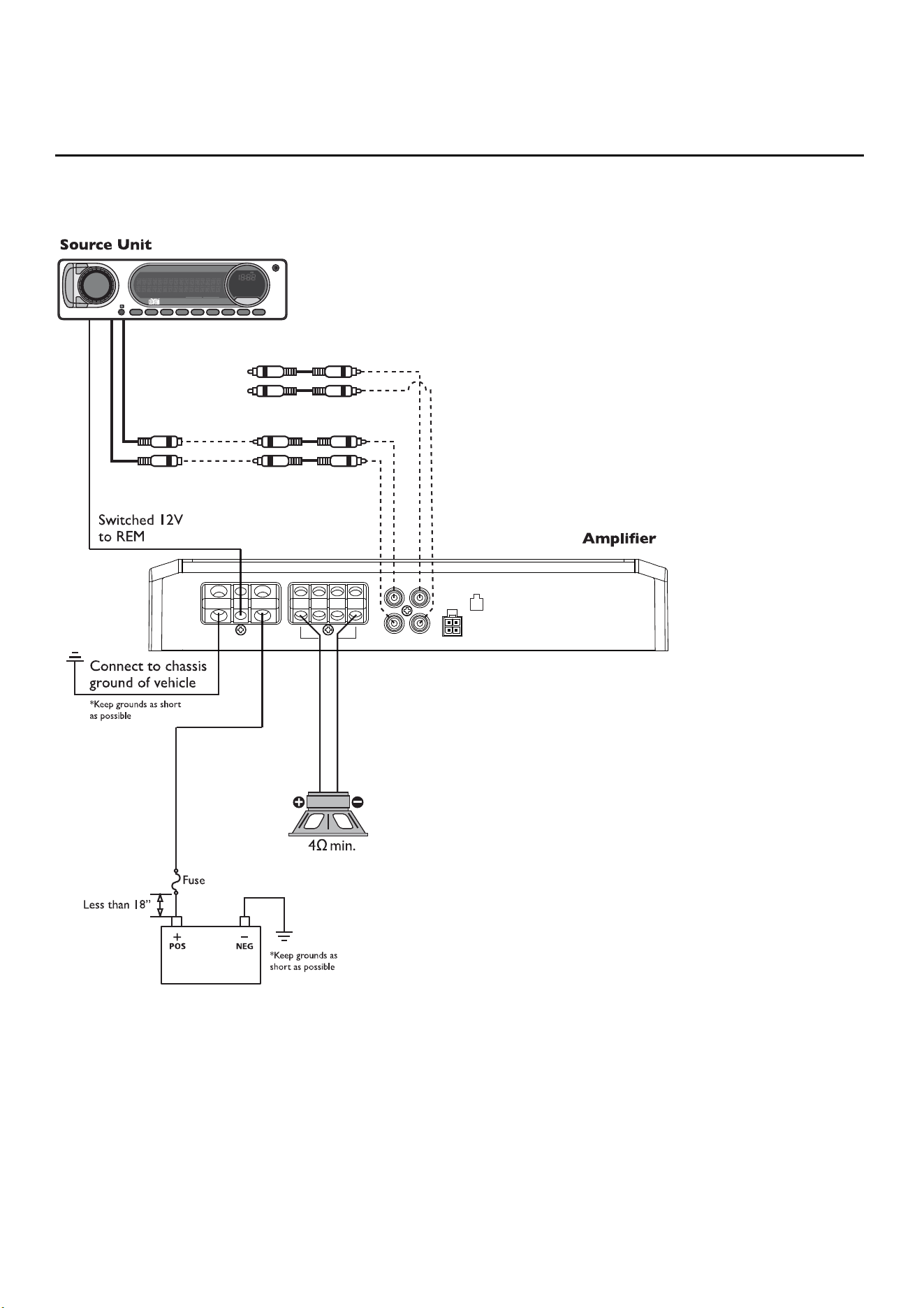
Mono Wiring
R250X1 & R500X1D
REMGND
L
R
INPUT
+
–
B+
SPEAKERS
HIGH LEVEL INPUT
REMOTE PUNCH LEVEL
L+R+
L
-
R
-
PASS-THRU
PASS-THRU
Connect to inputs
of 2nd amplifier
*Installation option for
multi-amp install
illus.-2.7 illus.-2.8
16
Installation
Parrallel Wiring*
R750-1D & R1200-1D
B+REMGND
+
–
+
–
PASS-THRU
Connect to inputs
of 2nd amplifier
*Installation option for
multi-amp install
*Paralleled internally for 1 � min. load.
illus.-2.9
17
Adjusting Gain
1. Turn amplifier gains to minimum (counter-clockwise).
2. Turn the source unit volume up to 7/8 maximum (or when
distortion is just inaudible).
3. Slowly increase amplifier gain control until adequate volume is
achieved.
NOTE: Best signal to noise and dynamic range are realized with gain set
to minimum. For a more in depth setting procedure, contact Rockford
Technical Support.
Avoid setting amplifier gain high as noise and
distortion will greatly increase.
Adjusting Crossover Frequency
Do the following individually for each channel.
Placing the crossover switch in the HP posi-
tion sets the amplifier to the High Pass mode,
enabling frequencies above the cut-off point to
pass, adjustable between 50-250Hz.
Placing the crossover switch in the AP position sets the amplifier to the All
Pass mode, preventing any crossover adjustment, allowing all frequencies
to pass.
Placing the crossover switch in the LP position sets the amplifier to the
Low Pass mode, enabling frequencies below the cut-off point to pass,
adjustable between 50-250Hz.
Turn the crossover adjustment knob all the way down. With the system
playing, turn the crossover adjustment knob up slowly until the desired
crossover point is achieved.
Input Switch
Setting this switch to the 2CH. position, switches the
inputs to a 2-channel mode, allowing connection to only
the front inputs with a 4-channel output.
Output controls function the same as if the amplifier was in 4-channel
mode.
All “ACTIVE” inputs must have RCA jacks connected.
Switch in 2CH. position,“ACTIVE” - Front channel inputs only.
Switch in 4CH. position,“ACTIVE” - All Front and Rear channel inputs.
Switch in 5CH. position,“ACTIVE” - All Front, Rear and Sub channel
inputs.
NOTE: When connecting to the 4-Channel inputs, be sure to route both
front and rear RCA cables tightly together.
Variable Phase
Allows you to conveniently switch the output phase of the
amplifier between 0° and 180°. This has the same effect as
physically reversing the Positive (+) and Negative (-) speaker wires.
High Level Input
High Level Inputs are used when you want to connect an amplifier to your
factory radio or an aftermarket radio that does not have low-level (RCA)
inputs. It allows you to use the signal coming from the speaker outputs as
an input source for the amplifier.
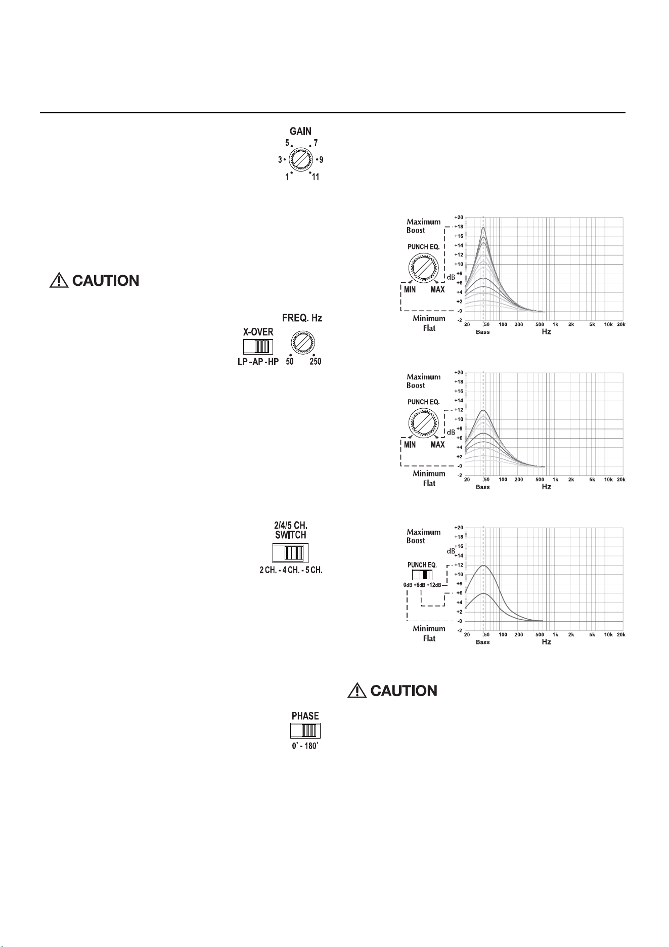
Punch EQ
This works along with the crossover switch on the amplifier. When set to
Low-Pass (LP) operation, this is a variable Bass Boost. When set to High-
Pass (HP) operation, this is a variable Mid-Bass and Treble Boost. When
set to All-Pass (AP) operation, both the Bass and Treble frequencies are
boosted. Set this to your personal preference while listening to the system.
Variable 0-+18dB @ 45Hz (R400-4D, R600-4D, R750-1D & R1200-1D)
Variable 0-+12dB @ 45Hz (R150X2, R250X1, R500X1D & R600X5)
Selectable: 0/+6dB/+12dB @ 45Hz (R250X4, R300X4 & R600X5)
Over excursion and subsequent damage may
occur at high levels of boost.
Remote Punch Level Control (Option)
Quick Install:
1. Using the screws supplied, install the mounting clip.
2. Slip the remote onto the mounting clip until it snaps into place.
3. Route and connect the cable to the remote and amplifier.
Operation:
4. When connected, the “Level Control” is linked and allows you to
remotely control the output level of the amplifier from the dash or
center console.
Operation
illus.-3.1
illus.-3.3
illus.-3.2
illus.-3.4
illus.-3.5
illus.-3.6
illus.-3.7
illus.-3.8

18
Troubleshooting
NOTE: If you are having problems after installation follow the Trouble-
shooting procedures below.
Check Amplifier for proper connections. Verify that POWER light
is on. If POWER light is on skip to Step 3, if not continue.
1. Check in-line fuse on battery positive cable. Replace if necessary.
2. Check fuse(s) on amplifier. Replace if necessary.
3. Verify that Ground connection is connected to clean metal on the
vehicle’s chassis. Repair/replace if necessary.
4. Verify there is 9 to 14.4 Volts present at the positive battery and
remote turn-on cable. Verify quality connections for both cables at
amplifier, stereo, and battery/fuseholder. Repair/replace if necessary.
Protect light is on.
1. If the Protect light is on, this is a sign of a possible short in the
speaker connections. Check for proper speaker connections and use
a volt/ohm meter to check for possible shorts in the speaker wiring.
Too low of a speaker impedance may also cause Protect to light.
Check Amplifier for audio output.
1. Verify good RCA input connections at stereo and amplifier. Check
entire length of cables for kinks, splices, etc. Test RCA inputs for AC
volts with stereo on. Repair/replace if necessary.
2. Disconnect RCA input from amplifier. Connect RCA input from test
stereo directly to amplifier input.
Check Amplifier if you experience Turn-on Pop.
1. Disconnect input signal to amplifier and turn amplifier on and off.
2. If the noise is eliminated, connect the REMOTE lead of amplifier to
source unit with a delay turn-on module.
OR
1. Use a different 12 Volt source for REMOTE lead of amplifier.
Check Amplifier if you experience excess Engine Noise.
1. Route all signal carrying wires (RCA, Speaker cables) away from
power and ground wires.
OR
1. Bypass any and all electrical components between the stereo and the
amplifier(s). Connect stereo directly to input of amplifier. If noise goes
away the unit being bypassed is the cause of the noise.
OR
1. Remove existing ground wires for all electrical components. Reground
wires to different locations. Verify that grounding location is clean,
shiny metal free of paint, rust etc.
OR
1. Add secondary ground cable from negative battery terminal to the
chassis metal or engine block of vehicle.
OR
1. Have alternator and battery load tested by your mechanic. Verify good
working order of vehicle electrical system including distributor, spark
plugs, spark plug wires, voltage regulator etc.
Troubleshooting Français

19
Troubleshooting Français
Caracté ristiques de conception (illus. 1.1)
Phase variable
Le contrôle de phase variable 0-180˚ permet à l’auditeur de modifier le temps d’arrivée des ondes sonores du
subwoofer par rapport aux mêmes fréquences à partir des enceintes principales.
Ré partiteur variable
Filtre incorporé 12 dB/octave Butterworth avec point de première convergence variable de 50 Hz à 250 Hz. (R750-
1D et R1200-1D ont un filtre infrasonique 12 dB/octave additionnel avec un point de première convergence variable
de 15 Hz à 40 Hz SS)
DEL alimentation/protection
La DEL alimentation s’allume en bleu lorsque l’unité est activée. La DEL protection/thermique s’allume en rouge
lorsque l’ampli surchauffe ou en présence de courts-circuits. Si cela se produit, l’ampli s’arrêtera automatiquement.
EQ Punch - Variable
Ce contrôle de variable fonctionne avec l’Interrupteur de répartiteur sur l’amplificateur, en stimulant les graves.
Bornes d’alimentation/REM
Les bornes d’alimentation et de terre sont des connecteurs câblés nickelés à vis de blocage et accepteront un
calibre 4 AWG. Les bornes d’alimentation et de terre sont des connecteurs câblés nickelés à vis de blocage et qui
accepteront un calibre 8 AWG.
Bornes d’enceinte
Les bornes d’enceinte sont des connecteurs câblés nickelés à vis de blocage (+ et -) et qui accepteront un calibre
8 AWG.
Interrupteur de répartiteur
Commutateur sélectionnable pour High-Pass (HP) ou All Pass (AP) ou Low-Pass (LP)
Phase variable
Le contrôle de phase variable 0-180˚ permet à l’auditeur de modifier le temps d’arrivée des ondes sonores du
subwoofer par rapport aux mêmes fréquences à partir des enceintes principales.
Ré partiteur variable
Filtre incorporé 12 dB/octave Butterworth avec point de première convergence variable de 50 Hz à 250 Hz. (R750-
1D et R1200-1D ont un filtre infrasonique 12 dB/octave additionnel avec un point de première convergence variable
de 15 Hz à 40 Hz SS)
DEL alimentation/protection
La DEL alimentation s’allume en bleu lorsque l’unité est activée. La DEL protection/thermique s’allume en rouge
lorsque l’ampli surchauffe ou en présence de courts-circuits. Si cela se produit, l’ampli s’arrêtera automatiquement.
EQ Punch - Variable
Ce contrôle de variable fonctionne avec l’Interrupteur de répartiteur sur l’amplificateur, en stimulant les graves.
Bornes d’alimentation/REM
Les bornes d’alimentation et de terre sont des connecteurs câblés nickelés à vis de blocage et accepteront un
calibre 4 AWG. Les bornes d’alimentation et de terre sont des connecteurs câblés nickelés à vis de blocage et qui
accepteront un calibre 8 AWG.
Bornes d’enceinte
Les bornes d’enceinte sont des connecteurs câblés nickelés à vis de blocage (+ et -) et qui accepteront un calibre
8 AWG.
Installation
Contenu
Considé rations d’installation
Voici une liste d’outils nécessaires pour l’installation:
Cette section traite de points concernant le véhicule dont il faut tenir compte pour l’installation de votre nouvel
ampli. Planifier à l’avance la disposition du système et les meilleurs acheminements de câblage permettra de
gagner du temps pour l’installation. Lors de l’aménagement de votre nouveau système, assurez-vous que chaque
composant est facilement accessible pour les réglages.
En cas de doute sur l’installation de ce système vous-même, faites-le installer par un technicien qualifié.
Attention: Avant l’installation, déconnectez la borne négative (-) de batterie pour prévenir tout dommage matériel,
tout incendie et/ou toute blessure éventuelle.
Attention: Avant de commencer toute installation, suivez ces simples règles :
1. Prenez soin de lire attentivement et de comprendre les instructions avant d’essayer d’installer l’appareil.
2. Par mesure de sécurité, déconnectez le fil négatif de la batterie avant de commencer l’installation.
3. Pour faciliter l’assemblage, il est recommandé d’acheminer tous les fils avant de monter l’appareil en place.
4. Acheminez tous les câbles RCA de façon groupée et à l’écart des fils à courant élevé.
5. Utilisez des connecteurs de haute qualité pour une installation fiable et pour minimiser la perte de signal
ou de puissance.
6. Réfléchissez avant de percer ! Faites attention de ne pas couper ou percer dans les réservoirs d’essence, les
conduites de carburant, les conduites de frein ou hydrauliques, les lignes de vide ou le câblage électrique
lors de tout travail sur un véhicule.
7. Ne faites jamais passer les fils sous le véhicule. Il vaut mieux les installer à l’intérieur du véhicule pour
assurer une meilleure protection.
8. Évitez d’acheminer les fils sur ou à travers des chants coupants. Utilisez des passe-câbles en caoutchouc ou
en plastique pour protéger tout fil acheminé à travers le métal, en particulier le pare-feu.
9. Protégez TOUJOURS la batterie et le circuit électrique des dommages potentiels à l’aide de fusibles ap-
propriés. Installez les porte-fusible et fusible appropriés sur le câble d’alimentation de +12 V à moins de 45
cm de la borne de batterie.
10. Lors de la mise à la masse au châssis du véhicule, grattez toute trace de peinture de la surface métallique
pour assurer une bonne connexion à la terre propre. Les connexions de masse doivent être aussi courtes que
possible et toujours connectées à du métal soudé à la carrosserie ou au châssis du véhicule. Les boulons de
ceinture de sécurité ne doivent jamais être utilisés pour la mise à la masse.
Emplacements de montage
Pour assurer une performance optimale, montez l’ampli avec un espace d’air d’au moins 2,5 cm autour du dis-
sipateur thermique de l’ampli et ce, pour fournir un refroidissement satisfaisant.
Montage dans le coffre
Un montage vertical ou à l’envers de l’ampli assure un refroidissement adéquat. Le montage de l’ampli sur le
plancher du coffre fournira le meilleur refroidissement de l’ampli.
Montage dans l’habitacle
Le montage de l’ampli dans l’habitacle est acceptable à condition qu’il reçoive suffisamment d’air pour se refroidir.
Si vous comptez installer l’ampli sous le siège du véhicule, prévoyez un écartement d’air d’au moins 2,5 cm autour
du dissipateur thermique de l’ampli.
Attention: Ne montez jamais cet appareil dans le compartiment moteur. Cela entraînerait l’annulation de la garantie.
Batterie et charge
Les amplificateurs exercent une charge accrue sur la batterie et le système de charge du véhicule. Nous vous con-
seillons de vérifier l’état de l’alternateur et de la batterie pour vous assurer que le circuit électrique peut supporter la
charge accrue de votre système stéréo. Les systèmes électriques ordinaires en bon état sont normalement capables
de fournir sans problème la charge supplémentaire requise par un ampli de série. Toutefois, la durée de vie de la
batterie et de l’alternateur peut s’en trouver légèrement diminuée. Pour maximiser la performance de votre ampli,
nous vous suggérons d’utiliser une batterie à usage intensif et un condensateur de stockage d’énergie.
Câ blage du système
Attention: Si vous ne vous sentez pas à l’aise pour effectuer vous-même le câblage de votre nouvel appareil,
veuillez confier son installation à votre distributeur local agréé Rockford Fosgate.
Attention: Avant l’installation, déconnectez la borne négative (-) de batterie pour prévenir tout dommage matériel,
tout incendie et/ou toute blessure éventuelle.
Attention: Évitez de faire passer les fils d’alimentation à proximité des câbles d’entrée de niveau bas, de l’antenne,
des câbles d’alimentation, des équipements ou faisceaux sensibles. Les fils d’alimentation transportent un courant
élevé et peuvent produire du bruit dans le système audio.
1. Planifiez l’acheminement des fils. Gardez les câbles RCA ensemble mais en les isolant des câbles
d’alimentation de l’ampli et des autres accessoires automobiles de forte puissance, en particulier les moteurs
électriques et ce, pour éviter que le signal audio ne subisse d’interférence de bruit provenant des champs
de rayonnement électriques. Si vous faites passer les fils par un pare-feu ou toute autre barrière métallique,
protégez-les à l’aide de bagues en plastique ou en caoutchouc pour éviter les courts-circuits. Conservez
toute la longueur des fils pour l’instant. Vous l’ajusterez plus tard.
2. Préparez le fil ROUGE (câble d’alimentation) qui devra être relié à l’ampli en dénudant 1 cm d’isolant de son
extrémité. Insérez la partie dénudée dans la borne B+, puis fixez le fil en vissant la vis sans tête.
REMARQUE : Le câble B+ DOIT comporter un fusible à 45 cm ou moins de la batterie du véhicule. Installez le porte-
fusible sous le capot et assurez-vous que les connexions sont étanches.
3. Coupez le fil ROUGE (câble d’alimentation) à moins de 45 cm de la batterie et épissez un porte-fusible en
ligne (non fourni). Voir les Spécifications en ce qui concerne la capacité du fusible à utiliser. N’installez pas
le fusible pour le moment.
4. Dénudez 1 cm de l’extrémité de batterie du câble d’alimentation et sertissez une cosse à anneau de taille
appropriée sur le câble. Connectez la cosse à borne positive de la batterie.
5. Préparez le fil NOIR (câble de mise à la masse) qui devra être relié à l’ampli en dénudant 1 cm d’isolant de
son extrémité. Insérez la partie dénudée dans la borne GROUND [masse], puis fixez le fil en vissant la vis
sans tête. Préparez la masse du châssis en grattant toute trace de peinture de la surface métallique et en net-
toyant soigneusement la surface pour éliminer tout dépôt de saleté et de graisse. Dénudez l’autre extrémité
du fil et fixez un connecteur en anneau. Fixez le câble au châssis à l’aide d’une vis non anodisée et d’une
rondelle en étoile.
REMARQUE : Gardez le fil NOIR (masse) aussi court que possible. Toujours inférieur à 75 cm.
6. Préparez le fil d’allumage à distance qui devra être relié à l’ampli en dénudant 1 cm d’isolant de son extrémité.
Insérez la partie dénudée dans la borne REMOTE [à distance], puis fixez le fil en vissant la vis sans tête.
Connectez l’autre extrémité du fil à distance à une source positive commutée de 12 volts. La tension com-
mutée provient généralement du câble d’ampli à distance de l’unité source. Si l’unité source ne dispose pas
de cette sortie, il est recommandé de raccorder un interrupteur mécanique en ligne avec une source de 12
volts pour activer l’ampli.
REMARQUE : Lors de l’utilisation du haut niveau pour signal d’entrée, la fonction d’allumage automatique est ac-
tive. Une fois l’allumage automatique activé, la REM devient une sortie pour allumer/éteindre jusqu’à deux amplis
additionnels ou autres accessoires.
7. Montez solidement l’ampli sir le véhicule ou le rack d’ampli. Prenez soin de ne pas fixer l’ampli sur des
panneaux en carton ou en plastique. Les vis pourraient en effet se décoller des panneaux sous l’effet des
vibrations de la route ou des arrêts soudains du véhicule.
8. Connectez le signal source en branchant dans les prises d’entrée RCA au niveau de l’ampli. Les plages de
sensibilité d’entrée vont de 150 mV - 12 V sont capables d’accepter un signal du haut niveau (enceinte) à
bas niveau (RCA).
REMARQUE : Toutes les entrées « ACTIVES » doivent avoir des prises RCA connectées. Commutateur en position
2CH., « ACTIVE » - Entrées de canal avant uniquement. Commutateur en position 4CH., « ACTIVE » - Toutes les
entrées de canaux avant et arrière. Commutateur en position 5CH, « ACTIVE » - Entrées de subwoofer pour sortie
de subwoofer. Lors de la connexion aux entrées 5 canaux, prenez soin d’acheminer les câbles RCA avant, arrière
et sub bien groupés.
Porte-fusible et fusible. (Voir spécifications
pour calibre de fusible)
Voltmètre/Ohmmètre
Pince à dénuder
Pince à sertir
Coupe-fils
Tournevis cruciforme n° 2
Clé de bornes de batterie
Perceuse à main avec mèches assorties
Connecteurs assortis
Longueur adéquate — Fil d’alimentation rouge
Longueur adéquate — Fil d’allumage à dis-
tance
Longueur adéquate — Fil de masse noir
Amplificateur principal
Visserie de montage
Clé Allen
Contrôle de niveau Punch
Connecteur à 4 broches Molex (le cas échéant)
Manuel d’installation et de fonctionnement

20
Françias
Attention: Assurez-vous toujours que l’ampli est hors tension ou déconnecté avant de connecter les câbles RCA et
ce, pour ne pas endommager l’amplifier et/ou les composants connectés.
Remarque : Lorsque l’installation requiert une entrée de haut niveau (enceinte), utilisez le connecteur à 4 broches
Molex pour attacher au câble d’enceinte du véhicule.
9. Connectez les enceintes. Dénudez les fils des enceintes de 1 cm et insérez la partie dénudée dans la borne de
l’enceinte, puis serrez la vis sans tête pour fixer le tout en place. Veillez à maintenir une polarité d’enceintes
appropriée. NE mettez AUCUN des fils d’enceinte à la masse et ce, pour prévenir tout fonctionnement in-
stable.
10. Effectuez une vérification finale du câblage du système terminé pour vous assurer que toutes les connexions
sont correctes. Vérifiez toutes les connexions d’alimentation et de mise à la masse en vue de fils effilochés et
de connexions desserrées pouvant causer des problèmes. Installez le fusible en ligne près de la connexion
de la batterie.
REMARQUE : Vérifiez les polarités appropriées de signal à l’aide des schémas.
Attention: Cet amplificateur n’est pas recommandé pour des charges d’impédance inférieures à 2 ohm stéréo/4 ohm
bridgées pour les canaux avant/arrière et 2 ohm pour le canal de subwoofer. Les modèles R750-1D et R1200-1D ne
sont pas recommandés pour des charges d’impédance inférieures à 1 ohm.
Ré glage du gain (illus. 3.1)
1. Faites tourner les gains d’amplificateur sur minimum (dans le sens contraire des aiguilles).
2. Faites tourner le volume de l’unité source jusqu’à 7/8 maximum (ou lorsque la distorsion est juste inaudible).
3. Augmentez lentement le contrôle de gain d’amplificateur jusqu’à obtention du volume adéquat.
REMARQUE : Le meilleur signal au bruit et à la gamme dynamique est réalisé avec un gain réglé sur minimum.
Pour une procédure de configuration en profondeur, contactez l’assistance technique de Rockford.
Attention: Évitez de régler le gain d’amplificateur sur haut car le bruit et la distorsion augmenteront considérable-
ment.
Ré glage de la fré quence de transition (illus. 3.2, 3.3)
Effectuez ce qui suit individuellement pour chaque canal.
Placer le commutateur de croisement en position HP règle l’amplificateur sur le mode High Pass, permettant aux
fréquences supérieures au point de coupure de passer, réglable entre 50 et 250 Hz.
Placer le commutateur de croisement en position AP règle l’amplificateur sur le mode All Pass, empêchant ainsi
tout ajustage de croisement, permettant à toutes les fréquences de passer.
Placer le commutateur de croisement en position LP règle l’amplificateur sur le mode Low Pass, permettant aux
fréquences inférieures au point de coupure de passer, réglable entre 50 et 250 Hz.
Faites tourner le bouton de réglage du répartiteur sur le réglage minimum. Le système en marche, faites lentement
tourner le bouton de réglage du répartiteur jusqu’à obtention du point de première convergence désiré.
Interrupteur d’entrée (illus. 3.4)
Régler ce sélecteur en position 2CH. commute les entrées vers un mode 2 canaux permettant ainsi une connexion
aux entrées avant uniquement avec une sortie 4 canaux.
Les commandes de sortie fonctionnent comme si l’amplificateur était en mode 4 canaux.
Toutes les entrées « ACTIVES » doivent avoir des prises RCA connectées.
Commutateur en position 2CH., « ACTIVE » - Entrées de canal avant uniquement.
Commutateur en position 4CH., « ACTIVE » - Toutes les entrées de canaux avant et arrière.
Commutateur en position 5CH., « ACTIVE » - Toutes les entrées de canaux avant, arrière et subwoofer.
REMARQUE : Lors de la connexion aux entrées 4 canaux, prenez soin d’acheminer les câbles RCA avant et arrière
bien groupés.
Phase variable (illus. 3.5)
Vous permet de commuter de manière pratique la phase de sortie de l’amplificateur entre 0° et 180°. Ceci a le
même effet qu’inverser physiquement les fils d’enceinte positif (+) et négatif (-).
Entré es de haut niveau
Les entrées de haut niveau sont utilisées lorsque vous souhaitez connecter un amplificateur à votre radio d’origine
ou une radio de marché secondaire qui n’a pas d’entrées (RCA) de bas niveau. Ceci vous permet d’utiliser le signal
venant des sorties de l’enceinte comme source d’entrée pour l’amplificateur.
EQ Punch
Ceci fonctionne avec l’interrupteur de répartiteur sur l’amplificateur. Quand réglé sur un fonctionnement Low-Pass
(LP), ceci est un Bass Boost variable. Quand réglé sur un fonctionnement High-Pass (HP), ceci est un Mid-Bass
et Treble Boost variable. Quand réglé sur un fonctionnement All-Pass (AP), les deux fréquences Bass [graves] et
Treble [aigus] sont stimulées. Réglez ceci à votre préférence personnelle tout en écoutant le système.
Variable 0-+18 dB à 45 Hz (R400-4D, R600-4D, R750-1D et R1200-1D) (illus. 3.6)
Variable 0-+12 dB à 45Hz (R150X2, R250X1, R500X1D et R600X5) (illus. 3.7)
Sélectionnable : 0/+6 dB/+12 dB à 45Hz (R250X4, R300X4 et R600X5) (illus. 3.8)
Attention: Une amplitude excessive et des dommages consécutifs peuvent se produire à de niveaux de boost.
Commande de niveau Punch à distance
Installation rapide:
1. À l’aide des vis fournies, installez le clip de fixation.
2. Faites glisser la télécommande dans le clip de fixation jusqu’à ce qu’elle s’enclenche en place.
3. Acheminez et connectez le câble à la télécommande et à l’amplificateur.
Fonctionnement:
4. Une fois connecté, la « commande de niveau » est reliée et vous permet de contrôler à distance le niveau de
sortie de l’amplificateur à partir du tableau de bord ou de la console centrale.
Dé pannage
REMARQUE : En cas de problèmes après l’installation, suivez les procédures de dépannage ci-dessous.
Vé rifiez que les connexions de l’ampli sont bien mises. Vé rifier que le voyant POWER est allumé. Si
c’est le cas, passez à l’étape 3, sinon poursuivez.
1. Vérifiez le fusible en ligne du câble positif de la batterie. Remplacez si nécessaire.
2. nspectez le ou les fusibles de l’ampli. Remplacez si nécessaire.
3. Vérifiez que la connexion de mise à la masse est connectée à du métal propre sur le châssis du véhicule.
Réparez/remplacez si nécessaire.
4. Vérifiez la présence d’un courant de 9 à 14,4 volts au niveau de la borne positive de la batterie et du câble
d’allumage à distance. Vérifiez la qualité des connexions des deux câbles au niveau de l’amplificateur, de la
stéréo et de la batterie et du porte-fusible. Réparez/remplacez si nécessaire.
Le voyant de protection est allumé.
1. Si le voyant de protection est allumé, cela indique la présence possible d’un court-circuit dans les connex-
ions des enceintes. Vérifiez si les connexions des enceintes sont bonnes et utilisez un voltmètre/ohmmètre
pour voir s’il y a des courts-circuits dans le câblage des enceintes. Le voyant de protection peut également
s’allumer si l’impédance des enceintes est trop basse.
Vérifiez la sortie audio de l’amplificateur.
1. Vérifiez que les connexions d’entrée RCA sont bonnes au niveau de la stéréo et de l’ampli. Vérifiez s’Il y a des
problèmes de torsion ou d’épissure sur toute la longueur des câbles, etc. Testez la présence de courant c.a.
au niveau des entrées RCA lorsque la stéréo est allumée. Réparez/remplacez si nécessaire.
2. Débranchez l’entrée RCA de l’ampli. Branchez l’entrée RCA de la stéréo test directement à l’entrée de l’ampli.
Vérifiez l’ampli si un crépitement se produit lorsque vous l’allumez.
1. Débranchez le signal d’entrée reçu par l’ampli, puis allumez et éteignez l’ampli.
2. Si le bruit disparaît, connectez le fil REMOTE de l’ampli à l’unité source avec un module d’allumage tem-
porisé.
OU
1. Utilisez une source de 12 volts différente pour le fil REMOTE de l’ampli.
Vérifiez l’ampli si un bruit de moteur excessif se produit.
1. Acheminez tous les fils de signal (RCA, câbles d’enceintes) à l’écart des fils d’alimentation et de masse.
OU
1. Contournez tous les composants électriques situés entre la stéréo et le ou les amplis. Connectez la stéréo
directement à l’entrée de l’ampli. Si le bruit disparaît, l’unité contournée est la cause du bruit.
OU
1. Retirez les fils de masse existants de tous les composants électriques. Branchez de nouveau les fils à la
masse mais à des emplacements différents. Vérifiez que l’emplacement de la masse est propre, que le métal
est brillant sans trace de peinture, de rouille, etc.
OU
1. Ajoutez un deuxième fil de masse allant de la borne négative de la batterie au métal du châssis ou au bloc-
moteur du véhicule.
OU
1. Faites effectuer par votre mécanicien un essai de charge au niveau de l’alternateur et de la batterie. Vérifiez
que le circuit électrique fonctionne correctement, notamment le distributeur, les bougies et leurs câbles, le
régulateur de tension, etc.

21
Características de diseñ o (illus. 1.1)
Fase variable
El control de fase variable de 0-180˚ permite que el oyente cambie el momento de llegada de las ondas sonoras
del subwoofer con respecto a las mismas frecuencias de los altavoces principales.
Cruce variable
Un filtro incorporado de 12dB/octava Butterworth con un punto de cruce variable desde 50 a 250Hz. (R750-1D y
R1200-1D tienen un filtro infrasónico adicional de 12dB/octava con un punto de cruce variable desde 15Hz hasta
40Hz SS)
LED de encendido/protecció n
El LED de encendido se ilumina color azul cuando se enciende la unidad. El LED de protección/térmico se ilumina
color rojo cuando se sobrecalienta el amplificador o si sufre cortocircuitos. El amplificador se apagará automáti-
camente si sucede esto.
Punch EQ - Variable
Este control variable funciona junto con el interruptor del cruce del amplificador reforzando las frecuencias de
bajos.
Alimentació n/Terminales REM
Los terminales de alimentación y tierra son conectores niquelados con tornillo prisionero y acomodan alambre cal-
ibre 4 AWG. El terminal REM es un conector niquelado con tornillo prisionero y acomoda alambre calibre 8 AWG.
Terminales del altavoz
Los terminales de altavoz son conectores niquelados de tornillo prisionero para cables (+ y -) aceptarán cables
de tamaño 8 AWG.
Conectores RCA Input/Pass-Thru
Los conectores RCA Inputs/Pass-Thru están niquelados para resistir el deterioro de las señales causado por la
corrosión. Estos Pass-Thru proporcionan una fuente conveniente para la conexión en margarita de amplificadores
adicionales sin tender un juego de cables RCA adicional desde la parte delantera del vehículo al amplificador
trasero en el vehículo.
Entradas de alto nivel - Entradas opcionales
Acepta señal de altavoz de alto nivel cuando utiliza el arnés Molex de 4 clavijas proporcionado.
Control remoto de nivel Punch
Controle de manera remota el nivel de salida del subwoofer del amplificador.
Punch EQ - Seleccionable
Este control seleccionable funciona junto con el interruptor del cruce del amplificador reforzando las frecuencias
de bajos.
Control de ganancia
El control de ganancia se usa para igualar la salida de la fuente de audio.
Interruptor de entrada
El ajuste de este interruptor a las entradas conectadas alinea la señal de salida de manera acorde o puede comple-
mentar las señales a los canales adicionales cuando no están conectados.
Conmutació n del cruce
Interruptor seleccionable para Pasa Altos (HP), Pasan Todos (AP) o Pasa Bajos (LP).
Índice
Consideraciones para la instalació n
La siguiente es una lista de herramientas necesarias para la instalación:
Esta sección se enfoca en algunas de las consideraciones de vehículos para instalar el amplificador nuevo. Pre-
planear la distribución de su sistema y las rutas de cableado le ahorrará tiempo de instalación. Cuando decida
la distribución de su nuevo sistema asegúrese de que pueda acceder fácilmente a cada componente para hacer
los ajustes.
Si no está seguro si debe hacer la instalación de este sistema usted mismo, haga que lo instale un técnico cali-
ficado.
Precaución: Antes de efectuar la instalación, desconecte el terminal negativo (-) de la batería para evitar daños a la
unidad, incendio y/o posiblemente lesiones.
Precaución: Antes de comenzar cualquier instalación, siga estas simples normas:
1. Asegúrese de leer cuidadosamente y de entender las instrucciones antes de tratar de instalar la unidad.
2. Por seguridad, desconecte el conductor negativo de la batería antes de comenzar la instalación.
3. Para facilitar el montaje, sugerimos que tienda todos los cables antes de montar su unidad en el sitio.
4. Tienda todos los cables RCA cerca unos de otros y alejados de los cables de alta corriente.
5. Utilice conectores de alta calidad para tener una instalación confiable y para reducir al mínimo las pérdidas
de señal o de potencia.
6. ¡Piense siempre antes de perforar! Tenga cuidado de no cortar ni perforar tanques de combustible, tuberías
de combustible, de frenos o hidráulicas, tuberías de vacío o cableado eléctrico al trabajar en cualquier
vehículo.
7. Nunca tienda cables abajo del vehículo. Tender los cables adentro del vehículo proporciona la mejor protec-
ción.
8. Evite tender cables arriba o a través de bordes filosos. Use arandelas aislantes de caucho para proteger los
cables tendidos a través de metal, especialmente en la mampara cortafuegos.
9. Proteja SIEMPRE la batería y el sistema eléctrico contra daños usando los fusibles correspondientes. Instale
el portafusibles y los fusible correspondientes en el cable de +12 V a una distancia menor de 45 cm del
terminal de la batería.
10. Al conectar la tierra del chasis del vehículo raspe la pintura del metal para asegurar una conexión buena y
limpia a tierra. Las conexiones a tierra se deben hacer lo más cortas posibles y siempre conectadas a metal
que esté soldado a la carrocería o al chasis del vehículo. Nunca se debe usar los pernos para los cinturones
de seguridad para hacer conexiones a tierra.
Ubicació n para el montaje
Para asegurar un rendimiento óptimo, monte el amplificador con una separación de por lo menos 2.5 cm alrededor
del disipador térmico del amplificador para permitir un enfriado correcto.
Montaje en la cajuela
El montaje vertical o invertido del amplificador proporcionará suficiente enfriamiento para el mismo. El montaje del
amplificador en el piso proporcionará el mejor enfriamiento del amplificador.
Montaje en el compartimiento de los pasajeros
Montar el amplificador en el compartimiento de los pasajeros funcionará siempre que se proporcione suficiente
cantidad de aire para que el amplificador se enfríe a sí mismo. Si va a montar el amplificador abajo del asiento del
vehículo, debe dejar por lo menos 2.5 cm de separación de aire alrededor del disipador térmico del amplificador.
Precaución: Nunca monte esta unidad en el compartimiento del motor. Montar la unidad en el compartimiento del
motor anulará la garantía.
Batería y carga
Los amplificadores aplicarán una carga mayor en la batería del vehículo y en el sistema de carga de la misma. No-
sotros recomendamos que compruebe el estado del alternador y la batería para asegurarse de que el sistema eléc-
trico tenga capacidad suficiente para manejar la mayor carga de su sistema estereofónico. Los sistemas eléctricos
estándar que se encuentren en buen estado deben ser capaces de manejar la carga adicional del amplificador serie
Prime sin problemas, aún cuando es posible que se acorte ligeramente la duración de la batería y el alternador.
Para maximizar el rendimiento de su amplificador, sugerimos que use una batería de servicio pesado y un capacitor
para el almacenamiento de energía.
Cableado del sistema
Precaución: Si no se siente seguro haciendo el cableado de su nueva unidad, consulte con su distribuidor local
Autorizado de Rockford Fosgate para que le haga la instalación.
Precaución: Antes de efectuar la instalación, desconecte el terminal negativo (-) de la batería para evitar daños a la
unidad, incendio y/o posibles lesiones.
Precaución: Evite tender cables de alimentación cerca de cables de entrada de bajo nivel, de antena, de potencia,
equipo sensible o arneses. Los cables de alimentación transportan corrientes bastante elevadas y podrían inducir
ruidos en el sistema de audio.
1. Planee el tendido de los cables. Mantenga juntos los cables RCA pero aislados de los cables de alimentación
del amplificador y de cualquier cable de alta potencia de accesorios eléctricos del automóvil, especialmente
de motores eléctricos. Esto se hace para evitar el acoplamiento del ruido de los campos magnéticos ir-
radiados en la señal de sonido. Al pasar los cables a través de la mampara cortafuegos o cualquier barrera
metálica, protéjalos con arandelas de plástico o caucho para evitar cortos circuitos. Deje los alambres largos
en este punto, para poder ajustarlos con exactitud más adelante.
2. Prepare el cable ROJO (cable de alimentación) para fijarlo al amplificador pelando 1 cm de aislamiento del
extremo del cable. Inserte el cable desnudo en el terminal B+ y apriete el tornillo de fijación para fijar el
cable en su sitio.
NOTA: Se DEBE instalar un fusible en el cable B+ a 45 cm o menos de distancia de la batería del vehículo. Instale
el portafusibles abajo del capó y asegúrese de que las conexiones sean herméticas.
3. Recorte el cable ROJO (cable de alimentación) a menos de 45 cm de la batería y empálmelo en un portafus-
ibles en línea (no proporcionado). Consulte en las especificaciones la capacidad del fusible que debe usar.
NO instale el fusible en este momento.
4. Pele 1 cm del extremo de la batería del cable de alimentación y conecte a presión un terminal de anillo del
tamaño correcto al cable. Use el terminal de anillo para conectar al borne positivo de la batería.
5. Prepare el cable NEGRO (cable de tierra) para fijarlo al amplificador pelando 1 cm de aislamiento del extremo
del cable. Inserte el cable desnudo en el terminal GROUND (tierra) y apriete el tornillo de fijación para fijar el
cable en su sitio. Prepare la tierra del chasis raspando la pintura de la superficie de metal y limpie completa-
mente el área para evitar suciedad y grasa. Pele el otro extremo del cable e instale un anillo conector. Fije el
cable al chasis por medio de un tornillo no anodizado y una arandela de estrella.
NOTA: Mantenga el largo del cable NEGRO (tierra) lo más corto posible. Siempre menos de 75 cm
6. Prepare el cable de encendido remoto para fijarlo al amplificador pelando 1 cm de aislamiento del extremo
del cable. Inserte el cable desnudo en el terminal REMOTO y apriete el tornillo de fijación para fijar el cable
en su sitio. Conecte el otro extremo del cable Remoto a una fuente de alimentación conmutada de 12 voltios.
El voltaje conmutado normalmente se toma del cable de encendido del amplificador remoto de la unidad
fuente. Si la unidad de fuente no tiene esta salida disponible, la solución remendada es cablear un interruptor
mecánico en línea con una fuente de 12 voltios para activar el amplificador.
NOTA: Al utilizar alto nivel para la señal de entrada la característica de encendido automático está activa. Con el
encendido automático encendido REM se transforma en el encendido y apagado para hasta dos amplificadores
adicionales u otros accesorios.
7. Monte el amplificador de manera segura en el vehículo o en un bastidor de amplificador. Tenga cuidado de
no montar el amplificador sobre paneles de cartón o de plástico. Hacerlo permitiría que se arranquen los
tornillos del panel debido a la vibración del camino o a parada súbita del vehículo.
8. Conecte desde la señal de origen enchufando los cables RCA en los conectores de entrada en el amplificador.
Las gamas de sensibilidad de la entradas van de 150 mV-12V para aceptar señales de alto nivel (altavoz)
hasta bajo nivel (RCA).
NOTA: Todas las entradas “ACTIVAS” tienen que tener conectados los conectores RCA. Interruptor en la posición
2CH, “ACTIVE” (ACTIVOS) — Sólo entradas del canal delantero. Interruptor en la posición 4CH, “ACTIVE” (AC-
TIVO) — Todas las entradas del canal delantero y trasero. Interruptor en la posición 5CH “ACTIVE” (ACTIVO)
- entradas Sub para la salida sub. Al conectar a las entradas de 5 canales, asegúrese de tender ambos cables RCA
delantero y trasero muy juntos.
Precaución: Asegúrese siempre de que la alimentación esté apagada en el amplificador antes de conectar cables
RCA. No hacerlo podría causar daños al amplificador y/o a los componentes conectados.
Nota: Cuando la instalación requiere una entrada de alto nivel (altavoces), use el conector Molex de 4 clavijas para
empalmar en el cableado de altavoces de su vehículo.
9. Conecte los altavoces. Pele 1 cm los cables del altavoz e inserte en el terminal del altavoz y apriete el tornillo
prisionero para fijar en su sitio. Asegúrese de mantener la polaridad correcta de los altavoces. NO conecte
a tierra ninguno de los conductores de los altavoces pues se podría causar un funcionamiento inestable.
10. Haga una comprobación final del cableado del sistema terminado para asegurar que todas las conexiones
estén bien hechas. Compruebe todas las conexiones de alimentación y a tierra para determinar si hay cables
pelados o conexiones sueltas que podrían causar problemas. Instale el fusible cerca de la conexión de la
batería.
NOTA: Siga los diagramas para mantener la polaridad correcta.
Precaución: No se recomienda este amplificador para cargas de impedancia menores de 2 ohmios estéreo/4 oh-
mios puenteado para los canales delantero/trasero y 2 ohmios para el canal sub. No se recomienda los modelos
R750-1D y R1200-1D para impedancias menores de 1 ohmio.
Español
Portafusibles y fusible (Consulte la capacidad
de los fusibles en las especificaciones)
Voltio-óhmetro
Pelacables
Alicates de engarzar
Pinza de corte
Destornillador Phillips No. 2
Llave para bornes de batería
Taladro de mano con brocas varias
Conectores varios
Largo adecuado – Cable rojo de alimentación
Largo adecuado – Cable de encendido remoto
Largo adecuado – Cable negro de puesta a
tierra
Amplificador Prime
Accesorios para el montaje
Llave Allen
Control de nivel Punch
Conector Molex de 4 clavijas (si tiene uno)
Manual de Instalación y Operación

22
Ajuste de la ganancia (illus. 3.1)
1. Gire la ganancia del amplificador al mínimo (sentido contrahorario)
2. Suba el volumen de la unidad fuente a 7/8 del máximo (o cuando apenas se pueda escuchar la distorsión).
3. Lentamente aumente el control de ganancia del amplificador hasta que se obtenga un volumen adecuado.
NOTA: Se obtiene la mejor relación de señal a ruido y gama dinámica con la ganancia ajustada en mínimo. Por un
procedimiento de ajuste más a fondo, comuníquese con el Apoyo Técnico de Rockford.
Precaución: Evite ajustar la ganancia del amplificador en un valor demasiado alto pues aumentará mucho el ruido
y la distorsión.
Ajuste de la frecuencia de cruce (illus. 3.2,3.3)
Haga lo siguiente individualmente para cada canal.
Colocar el interruptor de cruce en la posición HP configura el amplificador en el modo pasa alto, permitiendo que
pasen las frecuencias menores que el punto de corte, ajustable entre 50 y 250Hz.
Colocar el interruptor de cruce en la posición AP configura el amplificador en el modo pasa todo, evitando el ajuste
de cruces, permitiendo que pasen todas las frecuencias.
Colocar el interruptor de cruce en la posición LP configura el amplificador en el modo pasa bajo, permitiendo que
pasen las frecuencias menores que el punto de corte, ajustable entre 50 y 250Hz.
Gire la perilla de ajuste de cruce totalmente hasta abajo. Con el sistema reproduciendo, gire lentamente hacia arriba
la perilla de ajuste de la frecuencia de cruce hasta que se logre el punto de cruce deseado.
Interruptor de entrada (illus. 3.4)
Colocar este interruptor en la posición 2CH, conmuta las entradas a un modo de 2 canales, permitiendo la conex-
ión sólo a las entradas delanteras con una salida de 4 canales.
Los controles de salida funcionan igual que si el amplificador estuviera en el modo de 4 canales.
Todas las entradas “ACTIVAS” tienen que tener conectados los conectores RCA.
Interruptor en la posición 2CH, “ACTIVE” (ACTIVO) — Sólo entradas del canal delantero.
Interruptor en la posición 4CH, “ACTIVE” (ACTIVO) — Todas las entradas del canal delantero y trasero.
Interruptor en la posición 5CH, “ACTIVE” (ACTIVO) — Todas las entradas del canal delantero, trasero y sub.
NOTA: Al conectar a las entradas de 4 canales, asegúrese de tender ambos cables RCA delantero y trasero muy
juntos.
Fase variable
Le permite conmutar convenientemente la fase de salida del amplificador entre 0° y 180°. Esto tiene el mismo
efecto que invertir físicamente los cables positivo (+) y negativo (-) del altavoz.
Entradas de alto nivel
Se usa las entradas de alto nivel cuando quiere conectar un amplificador a su radio de fábrica o a una radio de ter-
ceros que no tiene entradas de bajo nivel (RCA). Le permite usar la señal que viene de las salidas de los altavoces
como una fuente de entrada para el amplificador.
Punch EQ
Esto funciona junto con el interruptor de cruce en el amplificador. Cuando está· ajustado para la operación en Pasa
Bajos (Low Pass, LP) esto es un Refuerzo de Bajos variable. Cuando está· ajustado para la operación en Pasa
Altos (High Pass, HP) esto es un Refuerzo de Bajos Medianos y Agudos variable. Cuando está ajustado para la
operación en Todos Pasan (All Pass, AP), se refuerzan ambas frecuencias Bajas y Altas. Ajuste esto de acuerdo a
su preferencia personal mientras escucha al sistema.
Variable 0-+18dB a 45Hz (R400-4D, R600-4D, R750-1D y R1200-1D) (illus. 3.6)
Variable 0-+12dB a 45Hz (R150X2, R250X1, R500X1D y R600X5) (illus. 3.7)
Se puede seleccionar: 0/+6dB/+12dB a 45Hz (R250X4, R300X4 y R600X5) (illus. 3.8
Precaución: A altos niveles de refuerzo puede producirse una sobrecarrera seguida de daños.
Control remoto de nivel Punch
Instalació n rá pida:
1. Instale el clip de montaje usando los tornillos proporcionados.
2. Deslice el control remoto en el clip de montaje hasta que calce en su sitio.
3. Tienda y conecte el cable a la unidad remota y conecte al amplificador.
Operació n:
4. Cuando está conectado, se enlaza el “Control de Nivel” y le permite controlar remotamente el nivel de salida
del amplificador desde el tablero o la consola central.
Solució n de problemas
NOTA: Si tiene problemas después de la instalación siga los procedimientos de diagnóstico a continuación.
Compruebe si el amplificador tiene las conexiones correctas. Compruebe que esté encendida la luz
POWER (ENCENDIDO). Si la luz de POWER (ENCENDIDO) está encendida vaya al Paso 3 de otra
manera, continú e.
1. Compruebe el fusible en línea en el cable positivo de la batería. Cámbielas si es necesario.
2. Compruebe los fusibles en el amplificador. Cámbielas si es necesario.
3. Compruebe que la conexión a tierra esté conectada a metal limpio en el chasis del vehículo. Repare o cambie
si es necesario.
4. Compruebe que haya 9 a 14.4 voltios en el positivo de la batería y en el cable de encendido de la unidad
remota. Compruebe la calidad de las conexiones de ambos cables en el amplificador, estéreo y batería/
portafusibles. Repare o cambie si es necesario.
La luz de protecció n está encendida.
1. Si la luz de protección está encendida, es una indicación de que posiblemente haya un corto en las con-
exiones del altavoz. Compruebe que las conexiones del altavoz estén bien hechas y use un voltio-óhmetro
para comprobar si hay un corto en el cableado de los altavoces. Una impedancia de altavoz demasiado baja
también puede causar que se ilumine la luz de protección.
Compruebe la salida de sonido del amplificador.
1. Compruebe si las conexiones de entrada RCA están bien en el estéreo y el amplificador. Compruebe todo
el largo del cable para ver si está retorcido, empalmado, etc. Pruebe las entradas RCA para determinar los
voltajes de CA teniendo el estéreo encendido. Repare o cambie si es necesario.
2. Desconecte la entrada RCA del amplificador. Conecte la entrada RCA desde el estéreo de prueba directamente
a la entrada del amplificador.
Compruebe el amplificador si escucha un sonido “Pop” cuando se enciende.
1. Desconecte la señal de entrada al amplificador y encienda y apague el amplificador.
2. Si se eliminó el ruido, conecte el conductor REMOTO del amplificador a la unidad de origen usando un
módulo de retardo del encendido.
O
1. Use una fuente de 12 voltios distinta para el conductor REMOTO del amplificador.
Compruebe el amplificador si experimenta demasiado ruido del motor.
1. Encamine todos los cables que transportan señales (cables RCA, de altavoz) alejados de los cables de
alimentación y de puesta a tierra.
O
1. Desvíe, omitiendo todos los componentes eléctricos entre el estéreo y los amplificadores. Conecte el estéreo
directamente a la entrada del amplificador. Si el ruido desaparece, la unidad que se está omitiendo es la que
está casando el ruido.
O
1. Retire los cables de puesta a tierra existentes de todos los componentes eléctricos. Vuelva a conectar a tierra
los cables en lugares distintos. Compruebe que la ubicación de la puesta a tierra esté limpia, metal brillante
libre de pintura, óxido, etc.
O
1. Agregue un cable de puesta a tierra secundaria desde el terminal negativo de la batería al chasis de metal o
al bloque del motor del vehículo.
O
1. Haga que su mecánico pruebe la carga del alternador y de la batería. Compruebe que el sistema eléctrico del
vehículo esté en buen estado de funcionamiento incluyendo el distribuidor, cables de las bujías, regulador
de voltaje etc.
Español

23
Gerätefunktionen
Variable Phase
Der von 0 bis 180˚ variable Phasenregler erlaubt dem Hörer, die Ankunftszeit der Schallwellen vom Subwoofer im
Verhältnis zu den gleichen Frequenzen von den Hauptlautsprechern zu verändern.
Variables Crossover
Ein integrierter 12 dB/Oktav-Butterworth-Filter mit einem zwischen 50 und 250 Hz variablen Crossover-Punkt.
(Die Modelle R750-1D und R1200-1D sind zusätzlich mit einem 12 dB/Oktav-Infraschallfilter ausgestattet, dessen
Crossover-Punkt zwischen 15 und 40 Hz SS variabel ist.)
Betriebs-/Schutz-LED
Die Betriebs-LED leuchtet blau, wenn das Gerät eingeschaltet ist. Die Schutz-/Thermal-LED leuchtet rot, wenn der
Verstärker heißläuft oder kurzschließt. Wenn dies eintritt, schaltet sich der Verstärker automatisch ab.
Punch-EQ - Variabel
Dieser variable Regler funktioniert zusammen mit dem Crossover-Schalter am Verstärker und boostet die Bassfre-
quenzen.
Strom-/Fernsteuerungsanschlü sse
Die Strom- und Masseanschlüsse sind vernickelte Stellschrauben-Kabelanschlüsse und nehmen 4 AWG auf. Der
Fernsteuerungsanschluss ist ein vernickelter Stellschrauben-Kabelanschluss und nimmt 8 AWG auf.
Lautsprecheranschlü sse
Die Lautsprecheranschlüsse sind vernickelte Stellschrauben-Kabelanschlüsse (+ und -) und nehmen 8 AWG auf.
RCA-Eingangs-/-Durchgangsbuchsen
Die RCA-Eingangs-/-Durchgangsbuchsen sind vernickelt, um der durch Korrosion verursachten Signalver-
schlechterung zu widerstehen. Der Durchgang bietet eine bequeme Quelle zur Verkettung eines zusätzlichen Ver-
stärkers, ohne dafür weitere RCA-Kabel vom vorderen Fahrzeugbereich nach hinten zum Verstärker zu verlegen.
Hochpegeleingänge - Wahlweise Eingänge
Nimmt bei Verwendung des beiliegenden 4-Pin-Molex-Kabelbaums ein Hochpegel-Lautsprechersignal auf.
Punch-Pegel-Fernsteuerung
Fernsteuert den Subwoofer-Ausgangspegel des Verstärkers.
Punch-EQ - Wählbar
Dieser wählbare Regler funktioniert zusammen mit dem Crossover-Schalter am Verstärker und boostet die Bassfre-
quenzen.
Gain-Regler
Der Gain-Regler dient dazu, den Ausgang der Audioquelle anzugleichen.
Eingangsschalter
Durch Einstellung dieses Schalters auf die angeschlossenen Eingänge wird das Ausgangssignal dementsprechend
ausgerichtet oder kann, wenn nicht angeschlossen, Signal zu zusätzlichen Kanälen hinzufügen.
Crossover-Schalter
Wahlschalter für Hochpass (HP), Allpass (AP) oder Tiefpass (LP)
Inhalt
Einbauü berlegungen
Die folgenden Werkzeuge werden für den Einbau benötigt:
Dieser Abschnitt konzentriert sich auf bestimmte Überlegungen zum Einbau Ihres neuen Verstärkers im Fahrzeug.
Vorausplanung Ihres Systemlayouts und der besten Verkabelungsrouten spart Zeit beim Einbau. Prüfen Sie bei
der Wahl eines Layouts für Ihr neues System, ob alle Komponenten leicht erreichbar sind, um Einstellungen vor-
zunehmen.
Wenn Sie beim Einbau des Geräts unsicher sind, lassen Sie es von einem qualifizierten Techniker einbauen.
Vorsicht: Entfernen Sie vor dem Einbau den negativen (-) Batteriepol, um Schäden am Gerät, Feuer bzw. mögliche
Verletzungen zu vermeiden.
Vorsicht: Befolgen Sie vor dem Einbau diese einfachen Regeln:
1. Lesen Sie die Anleitung sorgfältig, bevor Sie versuchen das Gerät einzubauen.
2. Entfernen Sie vor dem Einbau aus Sicherheitsgründen das negative Kabel von der Batterie.
3. Um die Montage zu erleichtern, empfehlen wir alle Kabel vor der Befestigung Ihres Geräts zu verlegen.
4. Verlegen Sie alle RCA-Kabel dicht zusammen und im Abstand zu jeglichen Hochstromkabeln.
5. Verwenden Sie nur Qualitätsstecker, um einen zuverlässigen Einbau zu gewährleisten und Signal- und
Stromverlust zu minimieren.
6. Denken Sie nach, bevor Sie bohren! Achten Sie darauf, nicht in den Benzintank, die Benzin-, Brems- oder
hydraulischen Leitungen, Vakuumleitungen oder Elektrokabel zu schneiden oder zu bohren, wenn Sie am
Fahrzeug arbeiten.
7. Verlegen Sie Kabel nie unter dem Fahrzeug. Die Kabel im Fahrzeug zu verlegen, bietet den besten Schutz.
8. Vermeiden Sie es, Kabel über scharfe Kanten zu verlegen. Verwenden Sie Gummi- oder Plastikringe, um
Kabel zu schützen, die durch Metall verlegt werden (besonders die Feuerwand).
9. Schützen Sie die Batterie und das elektrische System IMMER durch ordnungsgemäße Sicherungen vor
Schäden. Installieren Sie die entsprechende Sicherungsfassung und Sicherung auf dem +12 V Stromkabel
maximal 45 cm vom Batteriepol.
10. Kratzen Sie bei der Erdung über das Fahrgestell alle Farbe vom Metall, um eine gute, saubere Masseverbind-
ung zu gewährleisten. Masseverbindungen sollten so kurz wie möglich und stets an Metall angeschlossen
sein, das an die Karosserie oder das Fahrgestell geschweißt ist. Die Bolzen der Sicherheitsgurte dürfen nicht
zur Erdung benutzt werden.
Befestigungsstellen
Um optimale Leistung zu gewährleisten, den Verstärker so einbauen, dass um die Wärmesenke herum zur ord-
nungsgemäßen Kühlung ein Luftspalt von wenigsten 2,5 cm verbleibt.
Befestigung im Kofferraum
Vertikale oder umgekehrte Befestigung des Verstärkers bietet angemessene Kühlung des Verstärkers. Befestigung
des Verstärkers auf dem Boden des Kofferraums bietet die beste Kühlung des Verstärkers.
Befestigung im Fahrgastraum
Befestigung im Fahrgastraum ist möglich, solange ausreichende Luftzufuhr zur Kühlung des Verstärkers
gewährleistet ist. Wenn Sie den Verstärker unter dem Sitz befestigen, muss ein Luftspalt von wenigstens 2,5 cm um
die Wärmesenke des Verstärkers herum vorhanden sein.
Vorsicht: Das Gerät darf nicht im Motorraum befestigt werden. Ein solcher Einbau führt zum Verlust der Garantie.
Batterie und Aufladen
Verstärker belasten die Fahrzeugbatterie und das Aufladungssystem zusätzlich. Wir empfehlen, dass Sie Ihre Lich-
tmaschine und den Batteriezustand prüfen, damit das elektrische System über ausreichende Kapazität verfügt, um
die zusätzliche Last Ihres Stereosystems zu bewältigen. Gängige Elektrosysteme, die sich in gutem Zustand befin-
den, sollten in der Lage sein, die zusätzliche Last eines Prime Series-Verstärkers problemlos zu bewältigen, jedoch
kann sich die Lebenserwartung der Batterie und Lichtmaschine geringfügig verringern. Um die Leistung Ihres Ver-
stärkers zu maximieren, empfehlen wir die Benutzung einer leistungsstarken Batterie und eines Energiespeichers.
Verkabelung des Systems
Vorsicht: Wenn Sie beim Verkabeln Ihres neuen Geräts unsicher sind, lassen Sie es bitte von einem Rockford
Fosgate-Vertragshändler einbauen.
Vorsicht: Entfernen Sie vor dem Einbau den negativen (-) Batteriepol, um Schäden am Gerät, Feuer bzw. mögliche
Verletzungen zu vermeiden.
Vorsicht: Vermeiden Sie es, Stromkabel in der Nähe von Niedrigpegel-Eingangskabeln, der Antenne, Stromadern,
sensiblem Gerät oder Kabelbäumen zu verlegen. Die Stromkabel führen eine erhebliche Menge an Strom und kön-
nen Geräusche in das Audiosystem eintragen.
1. Die Kabelwege im Voraus planen. RCA-Kabel eng zusammen aber isoliert von den Stromkabeln des Verstärk-
ers und anderem Hochstrom-Autozubehör – besonders elektrischen Motoren – verlegen. Dadurch wird die
Einkopplung von Geräuschen aus dem elektrischen Strahlungsfeld in das Audiosignal vermieden. Bei der
Verlegung von Kabeln durch die Feuerwand oder über andere Metallbarrieren zum Schutz Plastik- oder
Gummiringe verwenden, um Kurzschlüsse zu vermeiden. Die Kabel zunächst etwas länger belassen, damit
die präzise Länge später festgelegt werden kann.
2. Das ROTE Kabel (Stromkabel) durch Abisolieren von 1 cm am Ende des Kabels vorbereiten. Den blanken
Draht in den „B+“-Anschluss einführen und die Einstellschraube anziehen, um das Kabel zu befestigen.
HINWEIS: Das B+-Kabel MUSS im Abstand von höchstens 45 cm von der Fahrzeugbatterie mit einer Sicher-
ung versehen werden. Die Sicherungsfassung unter der Motorhaube anbringen und gewährleisten, dass die An-
schlüsse wasserdicht sind.
3. Den ROTEN Draht (Stromkabel) höchstens 45 cm von der Batterie abisolieren und eine Inline-Sicherungsfas-
sung (liegt nicht bei) einspleißen. Die erforderliche Nennleistung der Sicherung ist in den Technischen Daten
aufgeführt. Die Sicherung zu diesem Zeitpunkt NOCH NICHT einbauen.
4. 1 cm vom Batterieende des Stromkabels abisolieren und einen Ringadapter von geeigneter Größe an das
Kabel crimpen. Den Anschlussring zum Anschließen an den positiven Pol der Batterie benutzen.
5. Das SCHWARZE Kabel (Massekabel) durch Abisolieren von 1 cm am Ende des Kabels zum Anschließen am
Verstärker vorbereiten. Den blanken Draht in den GROUND-Anschluss einführen und die Einstellschraube
anziehen, um das Kabel zu befestigen. Die Fahrgestellerdung durch Abkratzen der Farbe von der Metallober-
fläche und gründliches Reinigen der Stelle von Schmutz und Schmiere vorbereiten. Das andere Ende des
Drahts abisolieren und an einem Anschlussring anbringen. Das Kabel mit einer nichtanodisierten Schraube
und einer Sternunterlegscheibe am Fahrgestell befestigen.
HINWEIS: Die Länge des SCHWARZEN Drahts (Masse) so kurz wie möglich belassen, jedoch in keinem Fall
länger als 75 cm.
6. Das Fernsteuerungskabel durch Abisolieren von 1 cm am Ende des Drahts zum Anschließen am Verstärker
vorbereiten. Den blanken Draht in den REMOTE-Anschluss einführen und die Einstellschraube anziehen, um
den Draht zu befestigen. Das andere Ende des Fernsteuerungskabels an eine geschaltete +12 V-Stromquelle
anschließen. Die geschaltete Spannung wird in der Regel von der Fernsteuerungsverstärker-Einschaltader
des Source-Geräts geholt. Falls das Source-Gerät diese Art von Ausgang nicht hat, ist es angeraten, eine
mechanische Schaltung inline mit einer 12 V-Quelle anzubringen, um den Verstärker einzuschalten.
HINWEIS: Bei Verwendung eines Hochpegels als Eingangssignals ist die Autoeinschaltfunktion aktiv. Wenn die
Autoeinschaltung aktiv ist, wird die Fernsteuerung zu einem Ausgang, um bis zu zwei weitere Verstärker oder
andere Peripheriegeräte ein- bzw. auszuschalten.
7. Den Verstärker gut am Fahrzeug oder am Verstärkergestell befestigen. Den Verstärker nicht versehentlich an
Papp- oder Plastikpaneelen befestigen. Auf diese Weise könnten sich die Schrauben aufgrund von Straßen-
vibration oder durch plötzliches Bremsen aus dem Paneel lösen.
8. Die Verbindung zum Source-Signal durch Einstöpseln in die RCA-Eingangsbuchsen am Verstärker herstel-
len. Die RCA-Eingänge können Signale entweder von Hochpegel (Lautsprecher) bis Niedrigpegel (RCA)
annehmen.
HINWEIS: Alle „ACTIVE“-Eingänge müssen an RCA-Buchsen angeschlossen sein. Schalter in der Zweikanalposi-
tion, „ACTIVE“ – nur Frontkanaleingänge. Schalter in der Vierkanalposition, „ACTIVE“ – alle Front- und Rearka-
naleingänge. Schalter in der Fünfkanalposition, „ACTIVE“ - Sub-Eingänge für Sub-Ausgang. Beim Anschluss an
die Fünfkanaleingänge darauf achten, dass die Front-, Rear- und Sub-RCA-Kabel dicht zusammen verlegt werden.
Vorsicht: Stets gewährleisten, dass der Betriebsschalter ausgeschaltet oder das Stromkabel vom Verstärker ab-
gezogen ist, bevor RCA-Kabel ansgeschlossen werden. Geschieht dies nicht, können der Verstärker und/oder die
angeschlossenen Komponenten beschädigt werden.
Hinweis: Wenn ein Hochpegel-(Lautsprecher-)Eingang für den Einbau erforderlich ist, den 4-Pin-Molex-Anschluss
benutzen, um an die Lautsprecherverkabelung Ihres Fahrzeugs anzuschließen.
9. Die Lautsprecher anschließen. Die Lautsprecherdrähte auf 1 cm abisolieren und in den Lautsprecheran-
schluss einführen. Die Feststellschraube anziehen, um die Drähte zu befestigen. Dabei die Lautsprecher-
polarität beachten. Die Lautsprecheradern NICHT über das Fahrgestell erden, da dies zu unstabilem Betrieb
führen kann.
10. Überprüfen Sie die Verkabelung des kompletten Systems ein letztes Mal um zu gewährleisten, dass alle
Anschlüsse korrekt sind. Überprüfen Sie alle Strom- und Masseanschlüsse auf beschädigte Drähte oder
lose Anschlüsse, die Probleme verursachen könnten. Bringen Sie die Inline-Sicherung in der Nähe des
Batterieanschlusses an.
HINWEIS: Beachten Sie zur ordnungsgemäßen Signalpolarität die Diagramme.
Vorsicht Dieser Verstärker wird nicht für Impedanzlasten unter 2 Ohm stereo oder 4 Ohm überbrückt für die Front-/
Rearkanäle und 2 Ohm für den Subkanal empfohlen. Die Modelle R750-1D und R1200-1D werden nicht für Im-
pedanzlasten unter 1 Ohm empfohlen.
Gain-Einstellung (illus. 3.1)
1. Die Gains am Verstärker auf Null drehen (im Gegenuhrzeigersinn).
2. Die Lautstärke des Source-Geräts bis auf höchstens 7/8 aufdrehen (oder wenn Verzerrung hörbar ist).
3. Den Gain-Regler des Verstärkers langsam aufdrehen, bis eine adäquate Lautstärke erreicht ist.
HINWEIS: Der beste Rauschabstand und Dynamikbereich werden erreicht, wenn Gain so niedrig wie möglich ein-
gestellt ist. Kontaktieren Sie hinsichtlich eines gründlicheren Einstellungsverfahrens die technische Unterstützung
von Rockford.
Eine hohe Einstellung des Gain am Verstärker vermeiden, da dies zu Geräuschen und Verzerrung führt.
Deutsch
Prime-Verstärker
Befestigungszubehör
Inbusschlüssel
Punch-Pegelregler
4-Pin-Molex-Anschluss (falls ausgerüstet)
Einbau- und Bedienungsanleitung
icherungsfassung und Sicherung (Siehe Tech-
nische Daten bezüglich des Bemessungsstroms
der Sicherung)
Spannungs- und Widerstandsmesser
Abisolierzange
Drahtkripper
Drahtschere
Kreuzschraubenzieher Nr. 2
Batteriestützenschlüssel
Handbohrer mit verschiedenen Bohrerspitzen
Verschiedene Anschlussstecker
Angemessene Länge rotes Stromkabel
Angemessene Länge Ferneinschaltkabel
Angemessene Länge schwarzes Massekabel

24
Einstellung der Crossover-Frequenz (illus. 3.2,3.3)
Folgendes für jeden Kanal einzeln durchführen.
Das Platzieren des Crossover-Schalters in der HP-Position schaltet den Verstärker in den Hochpassmodus und
erlaubt so das Passieren von Frequenzen oberhalb des Grenzpunkts. Eine Einstellung zwischen 50 und 250 Hz
ist möglich.
Das Platzieren des Crossover-Schalters in der AP-Position schaltet den Verstärker in den Allpassmodus und ver-
hindert jegliche Crossover-Einstellung. Dadurch können alle Frequenzen passieren.
Das Platzieren des Crossover-Schalters in der TP-Position schaltet den Verstärker in den Tiefpassmodus und
erlaubt so das Passieren von Frequenzen unterhalb des Grenzpunkts. Eine Einstellung zwischen 50 und 250 Hz
ist möglich.
Den Crossover-Regler ganz nach unten drehen. Während das System spielt, den Crossover-Regler langsam nach
oben drehen, bis der gewünschte Crossover-Punkt erreicht ist.
Eingangsschalter (illus. 3.4)
Einstellung dieses Schalters auf die Zweikanalposition schaltet die Eingänge in einen Zweikanalmodus und er-
möglicht den Anschluss eines Vierkanalausgangs nur an die Fronteingänge.
Die Ausgangsregler funktionieren in derselben Weise, als befände sich der Verstärker im Vierkanalmodus.
Alle „ACTIVE“-Eingänge müssen an RCA-Buchsen angeschlossen sein.
Schalter in der Zweikanalposition, „ACTIVE“ – nur Frontkanaleingänge.
Schalter in der Vierkanalposition, „ACTIVE“ – alle Front- und Rearkanaleingänge.
Schalter in der Fünfkanalposition, „ACTIVE“ - Alle Front-, Rear- und Subkanaleingänge.
HINWEIS: Beim Anschluss an die Vierkanaleingänge darauf achten, dass die Front- und Rear-RCA-Kabel dicht
zusammen verlegt werden.
Variable Phase (illus. 3.5)
Erlaubt die bequeme Schaltung der Ausgangsphase des Verstärkers zwischen 0° und 180°. Dies hat diesselbe
Wirkung wie die tatsächliche Umkehrung der positiven (+) und negativen (-) Lautsprecherkabel.
Hochpegeleingä nge
Hochpegeleingänge werden benutzt, wenn Sie einen Verstärker an Ihr bereits im Fahrzeug eingebautes Radio oder
ein Zubehörmarktsradio anschließen möchten, das keine Niedrigpegeleingänge (RCA) hat. Dies erlaubt Ihnen, das
von den Lautsprecherausgängen kommende Signal als Eingangsquelle für den Verstärker zu verwenden.
Punch-EQ
Er funktioniert zusammen mit dem Crossover-Schalter am Verstärker. Wenn er auf Tiefpass-Betrieb (LP) geschaltet
ist, ist er ein variabler Bass-Boost. Wenn er auf Hochpass-Betrieb (HP) geschaltet ist, ist er ein variabler Mid-
Bass- und Treble-Boost. Wenn er auf Allpass-Betrieb (AP) geschaltet Ist, werden sowohl die Bass- als auch Treble-
Frequenzen geboostet. Stellen Sie diesen entsprechend Ihrer persönlichen Vorliebe ein, während Sie das System
anhören.
Von 0 bis +18 dB bei 45 Hz variabel (R400-4D, R600-4D, R750-1D und R1200-1D) (illus. 3.6)
Von 0 bis +12 dB bei 45 Hz variabel (R150X2, R250X1, R500X1D und R600X5) (illus. 3.7)
Wählbar: 0/+6 dB/+12 dB bei 45 Hz (R250X4, R300X4 und R600X5) (illus. 3.8)
Vorsicht: Auslenkung und nachfolgender Schaden können bei hohen Boost-Pegeln auftreten.
Punch-Pegel-Fernsteuerung
Schnelleinbau:
1. Die Befestigungsklemme mit den beiliegenden Schrauben anbringen.
2. Die Fernsteuerung auf die Befestigungsklemme schieben, bis sie einschnappt.
3. Das Kabel von der Fernsteuerung verlegen und am Verstärker anschließen.
Bedienung:
4. Nach Anschließen ist die „Pegelsteuerung“ verbunden und erlaubt die Fernsteuerung des Ausgangspegels
am Verstärker vom Armaturenbrett oder der Mittelkonsole aus.
Fehlerbeseitigung
HINWEIS: Sollten Sie nach dem Einbau Probleme haben, befolgen Sie zur Fehlerbeseitigung die nachfolgenden
Schritte:
Prü fen, ob der Verstärker ordnungsgemäß angeschlossen ist. Prü fen, ob die POWER-Anzeige au-
fleuchtet. Leuchtet die POWER-Anzeige auf, bei Schritt 3 weiterlesen; falls nicht, hier weiterlesen.
1. Die Inline-Sicherung am positiven Kabel der Batterie prüfen. Falls erforderlich, ersetzen.
2. Die Sicherung(en) am Verstärker prüfen. Falls erforderlich, ersetzen.
3. Prüfen, ob das Massekabel an sauberem Metall am Fahrgestell angeschlossen ist. Falls erforderlich, repa-
rieren bzw. ersetzen.
4. Prüfen, ob 9 bis 14,4 Volt am positiven Batteriepol und Fernsteuerungskabel vorliegen. Prüfen, ob ord-
nungsgemäße Verbindungen beider Kabel am Verstärker, Source-Gerät und der Batterie/Sicherungsfassung
vorliegen. Falls erforderlich, reparieren bzw. ersetzen.
Schutzanzeige leuchtet.
1. Falls die Schutzanzeige leuchtet, liegt möglicherweise ein Kurzschluss in den Lautsprecherverbindungen vor.
Den ordnungsgemäßen Anschluss der Lautsprecher überprüfen und mit einem Spannungs-/Widerstands-
messer auf mögliche Kurzschlüsse in den Lautsprecherkabeln testen. Eine zu niedrige Lautsprecherimpen-
danz kann ebenfalls zum Aufleuchten der Schutzanzeige führen.
Den Audioausgang des Verstä rkers prü fen.
1. Prüfen, ob gute RCA-Eingangsverbindungen am Source-Gerät und Verstärker bestehen. Die Kabel in ihrer
gesamten Länge auf Knicke, Spleißungen usw. überprüfen. Die RCA-Eingänge auf AC-Volt prüfen, während
das Source-Gerät eingeschaltet ist. Falls erforderlich, reparieren bzw. ersetzen.
2. Den RCA-Eingang vom Verstärker abziehen. Den RCA-Eingang vom Test-Source-Gerät direkt am Ver-
stärkereingang anschließen.
Prü fen, ob der Verstärker einen Einschalteknall abgibt.
1. Das Eingangssignal vom Verstärker abziehen und den Verstärker ein- und ausschalten.
2. Wird das Geräusch so eliminiert, die REMOTE-Ader des Verstärkers mit einer Einschalteverzögerung am
Source-Gerät anschließen.
ODER
1. Eine andere 12-Volt-Quelle für die REMOTE-Ader des Verstärkers benutzen.
Prü fen, ob der Verstärker Motorengeräusche widergibt.
1. Alle Signal-führenden Kabel (RCA-, Lautsprecherkabel) im Abstand von Strom- und Massekabeln verlegen.
ODER
1. Alle elektronischen Komponenten zwischen der Stereoanlage und dem bzw. den Verstärker(n) umgehen. Das
Source-Gerät direkt am Eingang des Verstärkers anschließen. Ist das Geräusch nicht länger zu hören, ist das
umgangene Gerät die Geräuschquelle.
ODER
1. Die vorhandenen Massekabel aller elektronischen Komponenten abziehen. Die Kabel an anderen Stellen
erneut erden. Prüfen, ob die Erdungsstelle sauberes, glänzendes Metall frei von Farbe, Rost usw. ist.
ODER
1. Ein zweites Massekabel vom negativen Batteriepol zum Fahrgestellmetall oder zum Motorblock des Fah-
rzeugs hinzufügen.
ODER
1. Die Lichtmaschine und Batterielast von Ihrem KFZ-Mechaniker testen lassen. Prüfen, ob sich das elek-
trische System des Fahrzeugs einschließlich Verteiler, Zündkerzen, Zündkerzenkabel, Spannungsregler usw.
in gutem Zustand befinden.
Deutsch

25
Caratteristiche di progettazione (illus. 1.1)
Fase variabile
Il controllo di fase variabile 0-180° consente a chi ascolta di modificare il momento di arrivo delle onde sonore del
subwoofer in relazione alle stesse frequenze provenienti dai diffusori principali.
Crossover variabile
Si tratta di un filtro incorporato Butterworth da 12 dB/ottava con un punto di crossover variabile tra 50 Hz e 250
Hz. (I modelli R750-1D e R1200-1D sono dotati di un filtro supplementare infrasonico da 12 dB/ottava con punto
di crossover variabile da 15Hz a 40Hz SS)
LED alimentazione/protezione
Il LED dell’alimentazione si illumina in blu quando l’unità è accesa. Il LED di protezione/termica si accende in
rosso quando l’amplificatore si surriscalda, o in caso di cortocircuito. In tal caso, l’amplificatore si spegne au-
tomaticamente.
Punch EQ - variabile
Questo controllo variabile funziona assieme all’interruttore del crossover sull’amplificatore per potenziare le fre-
quenze basse.
Terminali alimentazione/REM
I terminali Power (alimentazione) e Ground (massa) sono connettori nichelati con vite di fermo per conduttori
e accettano fili 4 AWG. Il terminale REM (remoto) è un connettore nichelato con vite di fermo per conduttori e
accetta fili 8 AWG.
Terminali dei diffusori
I terminali dei diffusori sono connettori nichelati con vite di fermo per conduttori (+ e -) in grado di accettare fili
di sezione 8 AWG.
Prese Ingresso/”pass-through” RCA
Le prese ingresso/pass-through RCA sono nichelate per opporsi alla degradazione di segnale dovuta a corrosione.
Le prese passanti forniscono un modo conveniente di collegare in catena altri amplificatori senza dover collegare
altri cavi RCA dalla parte anteriore del veicolo alla posizione posteriore dell’amplificatore.
Ingressi alto livello - Ingressi opzionali
Accettano segnale del diffusore di alto livello quando si utilizza il cablaggio Molex a 4 pin in dotazione.
Comando a distanza di livello Punch
Comanda a distanza il livello in uscita dell’amplificatore per il subwoofer .
Punch EQ - selezionabile
Questo controllo selezionabile funziona assieme all’interruttore di crossover sull’amplificatore per potenziare le
frequenze basse.
Controllo del guadagno
Il comando di controllo del guadagno serve ad accoppiarsi con l’uscita della fonte audio.
Interruttore d’ingresso
L’impostazione di questo interruttore sugli ingressi collegati consente di allineare il segnale in uscita di conseg-
uenza, ovvero di supplementare il segnale a canali aggiuntivi quando non è collegato.
Crossover variabile
Si tratta di un filtro Butterworth da 12 dB/ottava con un punto di crossover variabile tra 50Hz e 250Hz.
Interruttore del crossover
Interruttore selezionabile per funzionamento High-Pass (HP), passa-alto, All Pass (AP), passa-tutto, o Low-Pass
(LP), passa-basso.
Contenuto
Considerazioni sull’installazione
Il seguente è l’elenco degli utensili/strumenti necessari per l’installazione:
La sezione presente si concentra su alcune considerazioni riguardanti il veicolo su cui installare il nuovo amplifi-
catore. La pianificazione anticipata della disposizione del sistema e dei percorsi dei fili ridurrà il tempo richiesto
per l’installazione. Nel decidere sulla disposizione del nuovo impianto, accertarsi che ogni elemento sia facile da
raggiungere per eseguire le regolazioni.
Se si teme di non riuscire a installare il sistema da se stessi, incaricare dell’installazione un tecnico qualificato
Avvertenza: Prima dell’installazione, scollegare il terminale negativo (-) della batteria per evitare danni all’unità,
incendio e/o il rischio di lesioni.
Avvertenza: Prima di iniziare un’installazione qualsiasi osservare le semplici indicazioni seguenti:
1. Accertarsi di leggere e comprendere tutte le istruzioni prima di tentare d’installare l’unità.
2. Per ragioni di sicurezza, scollegare il conduttore negativo della batteria prima d’iniziare l’installazione.
3. Per facilitare il montaggio, si consiglia di predisporre tutti i fili in loco prima di fissare l’unità in posizione.
4. Mantenere i cavi RCA vicini uno all’altro e lontani da qualsiasi filo ad alta corrente.
5. Per ottenere un’istallazione affidabile, con perdita minima di segnale o potenza, usare connettori di alta
qualità.
6. Rifletterci bene prima di fare fori col trapano! Quando si lavora su un veicolo, fare sempre attenzione a non
intaccare o praticare fori sul serbatoio e sui tubi della benzina, sui tubi idraulici o su quelli dei freni, sui tubi
sottovuoto e sulle linee dell’impianto elettrico.
7. Non far passare mai i fili sul fondo del veicolo. I percorsi dei fili all’interno del veicolo forniscono la pro-
tezione migliore.
8. Evitare di far passare i fili su o attraverso bordi taglienti. Usare guarnizioni di gomma o di plastica per proteg-
gere i fili che attraversano pareti metalliche, specialmente quelle tagliafiamma.
9. tilizzare SEMPRE fusibili adeguati per proteggere la batteria e l’impianto elettrico contro i danni. Installare
il portafusibili e fusibile corretti sul filo di alimentazione a +12 V entro 45 cm del terminale della batteria.
10. Quando si esegue la messa a terra su telaio del veicolo, raschiare completamente la vernice dal metallo per
garantire una connessione a massa buona e pulita. I collegamenti a massa dovrebbero essere il più corti
possibile, e sempre su una parte metallica saldata al corpo principale o telaio del veicolo. I bulloni delle
cinture di sicurezza non dovrebbero essere mai usati per il collegamento a massa.
Posizioni di montaggio
Per garantire le prestazioni migliori, montare l’amplificatore con uno spazio libero di almeno 2,5 cm tutt’attorno il
dissipatore di calore per ottenere il raffreddamento adeguato.
Montaggio nel bagagliaio
Il montaggio dell’amplificatore in posizione verticale o invertita sarà sufficiente a fornire adeguato raffreddamento
all’unità. Il montaggio dell’amplificatore sul pavimento del bagagliaio consente il raffreddamento migliore.
Montaggio nella cabina passeggeri
Il montaggio dell’amplificatore nella cabina passeggeri è accettabile sempre che si fornisca spazio adeguato cir-
costante per consentirne il raffreddamento. Se si pensa di montare l’amplificatore sotto il sedile dell’automobile,
occorre che ci sia uno spazio di almeno 2,5 cm tutt’attorno il dissipatore di calore.
Avvertenza: Non installare mai questa unità nello scomparto del motore. L’installazione nello scomparto del motore
annullerà la garanzia.
Batteria e carica
Gli amplificatori aggiungono un carico supplementare sulla batteria e sull’impianto di carica del veicolo. Si consi-
glia di verificare le condizioni della batteria e dell’alternatore per garantire che l’impianto elettrico abbia la capacità
sufficiente per gestire il carico superiore creato dal sistema stereo. Gli impianti elettrici di serie in buone condizioni
dovrebbero essere in grado di gestire senza problemi il carico extra di un amplificatore Prime Series, anche se la
durata della batteria e dell’alternatore potrà risultare un po’ ridotta. Per ottimizzare le prestazioni dell’amplificatore
si consiglia di utilizzare una batteria per lavori pesanti e un condensatore di accumulo di energia.
Cablaggio del sistema
Avvertenza: Se non ci si sente a proprio agio con il cablaggio della nuova unità, rivolgersi per l’installazione al
rivenditore autorizzato locale di Rockford Fosgate.
Avvertenza: Prima dell’installazione, scollegare il terminale negativo (-) della batteria per evitare danni all’unità,
incendio e/o il rischio di lesioni.
Avvertenza: Evitare di far passare i fili di alimentazione in vicinanza a cavi d’ingresso di livello basso, antenna,
conduttori dell’alimentazione e apparecchiature o cablaggi delicati. I fili di alimentazione portano una corrente
notevole e possono indurre disturbi nell’impianto audio.
1. Pianificare il percorso dei fili. Tenere i cavi RCA vicini assieme ma isolati dai cavi di alimentazione
dell’amplificatore e da ogni accessorio ad alta potenza, specialmente i motori elettrici. Ciò serve a evitare di
accoppiare al segnale audio disturbi creati da campi elettrici radiati. Quando si fanno passare i fili attraverso
una parete tagliafiamma, o altra barriera metallica, si consiglia di proteggerli con guarnizioni di gomma o di
plastica per evitare cortocircuiti. A questo punto lasciare che i fili siano di lunghezza abbondante per poterli
regolare dopo con più precisione.
2. Predisporre il filo ROSSO (cavo di alimentazione) per collegamento all’amplificatore spelando l’estremità del
suo rivestimento isolante per una lunghezza di 1 cm. Inserire il filo denudato nel terminale B+ e serrare la vite
di fermo per garantire che il cavo si mantenga a posto in modo sicuro.
NOTA: il cavo B+ deve essere dotato di fusibile a 45 cm o meno di distanza dalla batteria del veicolo. Installare il
portafusibili sotto il cofano e accertarsi che le connessioni siano a tenuta stagna.
3. Tagliare il filo ROSSO (cavo di alimentazione) a 45 cm dalla batteria e collegarvi un portafusibili in linea
(non in dotazione). Per il valore nominale del fusibile da usare vedere i dati tecnici. NON installare il fusibile
a questo punto.
4. Spelare 1 cm dall’estremità sul lato batteria del cavo di alimentazione e strozzare sul cavo un terminale ad an-
ello di dimensione opportuna. Servirsi del terminale ad anello per collegare il cavo al positivo della batteria.
5. Predisporre il filo NERO (cavo di messa a terra) per collegamento all’amplificatore spelando l’estremità
del suo rivestimento isolante per una lunghezza di 1 cm. Inserire il filo denudato nel terminale GROUND
(MASSA) e serrare la vite di fermo per garantire che il cavo si mantenga a posto in modo sicuro. Preparare il
punto di messa a terra sul telaio raschiando la vernice dalla superficie metallica e pulendo a fondo l’area per
togliere sporco e grasso. Spelare l’altra estremità del filo e attaccarvi un connettore ad anello. Fissare il cavo
al telaio usando una vite non anodizzata e una rondella dentata.
NOTA: tenere la lunghezza del filo NERO (massa) il più corta possibile. Sempre meno di 75 cm.
6. Predisporre il filo di accensione del comando a distanza per collegamento all’amplificatore spelando
l’estremità del suo rivestimento isolante per una lunghezza di 1 cm. Inserire il filo denudato nel terminale
REMOTE (A DISTANZA) e serrare la vite di fermo per garantire che il filo si mantenga a posto in modo sicuro.
Collegare l’altra estremità del filo a distanza a una fonte commutata positiva di 12 V. La tensione commutata
proviene normalmente dall’amplificatore o dal conduttore remoto dell’unità fonte di segnale. Se l’unità sor-
gente non dispone di questa uscita, la soluzione consigliata è di collegare un interruttore meccanico in linea
con una fonte a 12 V per attivare l’amplificatore.
NOTA: quando si usa il livello alto per il segnale in ingresso, la funzione di inserimento automatico è attiva. Con
l’attivazione automatica attiva, REM (A DISTAN ZA) diviene un’uscita per accendere/spegnere sino a due amplifi-
catori supplementari o altri accessori.
7. Montare l’amplificatore in modo sicuro sul veicolo o in apposito contenitore di alloggio. Prestare attenzione
per non montare l’amplificatore su pannelli di cartone o plastica. Facendolo si rischia che le viti si stacchino
dal pannello con le vibrazioni durante la marcia o in caso di fermate brusche.
8. Collegare dal segnale sorgente infilando negli ingressi RCA presso l’amplificatore. La sensitività in ingresso
varia da 150 mV a 12 V per accettare sia il segnale di livello alto (diffusore) che quello di livello basso (RCA).
NOTA: tutti gli ingressi “ATTIVI” devono avere jack RCA collegati. Interruttore in posizione 2CH. “ATTIVO”: solo
ingressi canali anteriori. Interruttore in posizione 4CH. “ATTIVO”: tutti gli ingressi canali anteriori e posteriori.
Interruttore in posizione 5CH “ATTIVO”: ingressi sub per uscite sub. Quando ci si collega agli ingressi 5-canali,
accertarsi di tenere assieme strettamente i cavi RCA anteriori e posteriori.
Avvertenza: Prima di collegare i cavi RCA accettarsi sempre che l’amplificatore sia spento e scollegato. Se non lo
si fa, si rischia di danneggiare l’amplificatore e/o i componenti a esso collegati.
Nota: quando l’installazione richiede ingressi di alto livello (diffusore), usare il connettore Molex a 4 pin per col-
legarsi al cablaggio dei diffusori del veicolo.
9. Collegare i diffusori. Spelare i fili per una lunghezza di 1 cm, inserirli nel connettore terminale e serrare le viti
di fermo per tenerli a posto in modo sicuro. Accertarsi di mantenere la corretta polarità del diffusore. NON
mettere a terra nessuno dei conduttori dei diffusori perché ciò potrebbe causare un funzionamento instabile.
10. Una volta terminato, eseguire un controllo finale del cablaggio dell’impianto per garantire che tutte le con-
nessioni siano state eseguite correttamente. Controllare che le connessioni di alimentazione e massa non
abbiano fili logorati e non siano allentate, cosa che potrebbe causare problemi. Installare un fusibile in linea
vicino al collegamento alla batteria.
NOTA: riferirsi agli schemi per la corretta polarità del segnale.
Avvertenza: Questo amplificatore non è consigliato per carichi d’impedenza al disotto di 2 Ohm stereo/4 Ohm in
parallelo per canali anteriori/posteriori e 2 Ohm per il canale sub. I modelli R750-1D and R1200-1D non sono
consigliati per carichi d’impedenza al disotto di 1 Ohm.
Amplificatore Prime
Articoli per il montaggio
Chiave a brugola
Comando livello Punch
Connettore Molex a 4 pin (se in dotazione)
Manuale d’installazione e funzionamento
Porta-fusibile e fusibile. (Per i valori nominali
dei fusibili, consultare le specifiche.)
Voltometro/ohmmetro
Pinza spelafilo
Pinza aggraffatrice
Tagliafili
Cacciavite Phillips n. 2
Chiave per morsetti batteria
Trapano a mano con punte assortite
Connettori assortiti
Un tratto di lunghezza adeguata di conduttore
rosso di alimentazione
Un tratto di lunghezza adeguata di conduttore di
accensione a distanza
Un tratto di lunghezza adeguata di conduttore
nero di massa
Italiano

26
Regolazione del guadagno (illus. 3.1)
1. Ruotare il comando del guadagno sull’amplificatore al minimo (in senso antiorario)
2. Ruotare il comando del volume dell’unità sorgente sino a 7/8 del massimo (o sino a quando la distorsione
diviene udibile).
3. Aumentare lentamente il comando di guadagno dell’amplificatore sino a ottenere un volume adeguato.
NOTA: il miglior rapporto segnale-rumore e la massima gamma dinamica si ottengono con il guadagno al minimo.
Per una procedura d’impostazione più dettagliata, contattare il servizio assistenza tecnica di Rockford.
Avvertenza: Si consiglia di non selezionare un guadagno troppo alto per non avere troppo rumore e distorsione.
Regolazione della frequenza di crossover (illus. 3.2,3.3)
Eseguire quanto segue separatamente per ciascun canale.
Posizionando l’interruttore di crossover sulla posizione HP (passa alto), l’amplificatore viene impostato sulla
modalità passa alto regolabile tra 50 e 250 Hz, permettendo il passaggio di frequenze sopra la frequenza di inter-
ruzione.
Posizionando l’interruttore di crossover sulla posizione AP (passa tutto), l’amplificatore viene impostato in mo-
dalità passa tutto, evitando eventuali regolazioni di crossover e permettendo il passaggio di tutte le frequenze.
Posizionando l’interruttore di crossover sulla posizione LP (passa basso), l’amplificatore viene impostato sulla
modalità passa basso regolabile tra 50 e 250 Hz, permettendo il passaggio di frequenze al di sotto della frequenza
di interruzione.
Ruotare la manopola di regolazione del crossover del tutto in basso. Con il sistema in funzione, ruotare la mano-
pola di regolazione per aumentare la frequenza di crossover lentamente fino a raggiungere il punto di crossover
desiderato.
Interruttore d’ingresso (illus. 3.4)
Impostando questo interruttore sulla posizione 2CH (2 canali), si commutano gli ingressi alla modalità a 2 canali,
permettendo il collegamento solo agli ingressi anteriori con un’uscita a 4 canali.
I comandi di uscita funzionano allo stesso modo di quando l’amplificatore era impostato su modalità a 4 canali.
Tutti gli ingressi “ATTIVI” devono avere jack RCA collegati.
Interruttore in posizione 2CH. “ATTIVO”: solo ingressi canali anteriori.
Interruttore in posizione 4CH. “ATTIVO”: tutti gli ingressi canali anteriori e posteriori.
Interruttore in posizione 5CH “ATTIVO”: tutti gli ingressi canali anteriori e posteriori e canale sub.
NOTA: quando ci si collega agli ingressi 4-canali, accertarsi di tenere assieme strettamente i cavi RCA anteriori
e posteriori.
Fase variabile (illus. 3.5)
Consente di selezionare comodamente la fase in uscita dell’amplificatore tra 0° e 180°. L’effetto è lo stesso dello
scambio fisico dei conduttori positivo (+) e negativo (-) dei diffusori.
Ingressi livello alto
Gli ingressi di livello alto sono usati quando si desidera collegare l’amplificatore alla radio di serie o a una radio di
mercato dei ricambi non dotata di ingressi di basso livello (RCA). Ciò consente di utilizzare il segnale proveniente
dall’uscita del diffusore come ingresso all’amplificatore.
Equalizzatore Punch
Questo funziona assieme all’interruttore di crossover sull’amplificatore. Quando è impostato su operazione Low-
Pass (LP), passa basso, questo rappresenta un valore variabile di aumento dei bassi. Quando è impostato su
operazione High-Pass (HP), passa alto, questo rappresenta un valore variabile di aumento dei bassi intermedi e
dei toni acuti. Quando è impostato su operazione All Pass (AP), passa tutto, sia le frequenze dei bassi che quelle
dei toni acuti sono aumentate. Impostare il comando sul valore preferito mentre si ascolta.
Variabile 0-+18 dB a 45 Hz (R400-4D, R600-4D, R750-1D e R1200-1D) (illus. 3.6)
Variabile 0-+12 dB a 45 Hz (R150X2, R250X1, R500X1D e R600X5) (illus. 3.7)
Selezionabile: 0/+6 dB/+12 dB a 45 Hz (R250X4, R300X4 e R600X5) (illus. 3.8)
Avvertenza: A livelli elevati di intensità si potrebbe raggiungere il limite della corsa, causando danni all’unità.
Comando a distanza di livello Punch
Installazione rapida:
1. Usando le viti fornite, installare la graffa di montaggio.
2. Fare scivolare il comando a distanza sulla graffa di montaggio fino a farlo scattare in posizione.
3. Portare il cavo dal comando a distanza all’amplificatore e collegarlo.
Funzionamento:
4. Una volta connesso, il “comando di livello” è collegato e consente di comandare a distanza il livello in uscita
dell’amplificatore dalla console centrale o dal cruscotto.
Individuazione e risoluzione dei problemi
NOTA: se si incontrano difficoltà dopo l’installazione, seguire le procedure sottostanti per l’individuazione e la
risoluzione dei problemi.
Controllare che le connessioni dell’amplificatore siano corrette. Verificare che la spia POWER (ALI-
MENTAZIONE) sia accesa. Se la spia POWER (ALIMENTAZIONE) è accesa passare al punto 3, altri-
menti continuare.
1. Controllare il fusibile in linea sul positivo della batteria. Sostituire se necessario.
2. Controllare il fusibile (o fusibili) sull’amplificatore. Sostituire se necessario.
3. Verificare che la connessione di massa sia collegata a una piastra metallica pulita dell’autotelaio. Riparare/
sostituire secondo necessità.
4. Verificare che vi è tensione tra 9 e 14,4 V al positivo della batteria e al cavo di accensione a distanza. Verifi-
care la qualità delle connessioni sia dei cavi dell’amplificatore che di quelli dello stereo, della batteria e del
portafusibili. Riparare/sostituire secondo necessità.
La spia di protezione è accesa.
1. La spia di protezione accesa può indicare la presenza di cortocircuito nei collegamenti dei diffusori. Control-
lare che i diffusori siano collegati correttamente e servirsi di un voltmetro/ohmetro per verificare che non
ci sono cortocircuiti nei loro collegamenti. Anche un’impedenza dei diffusori troppo bassa può causare
l’accensione della spia di protezione.
Controllare l’uscita audio dell’amplificatore.
1. Verificare che le connessioni d’ingresso RCA siano buone sia all’amplificatore che allo stereo. Controllare i
cavi per tutta la loro lunghezza per accertare che non ci siano piegature, giunzioni, ecc. Sottoporre a prova gli
ingressi RCA per tensione a corrente alternata con lo stereo acceso. Riparare/sostituire secondo necessità.
2. Scollegare gli ingressi RCA dall’amplificatore. Collegare gli ingressi RCA dallo stereo di prova direttamente
all’ingresso dell’amplificatore.
Controllare l’amplificatore se si verifica uno schiocco all’accensione.
1. Scollegare il segnale in ingresso all’amplificatore e accendere e spegnere l’amplificatore.
2. Se il disturbo sparisce, collegare il conduttore REMOTE (A DISTANZA) dell’amplificatore all’unità sorgente
con un modulo di ritardo all’accensione.
O
1. Usare ona fonte 12 V diversa per il conduttore REMOTE (A DISTANZA) dell’amplificatore.
Controllare l’amplificatore se si verificano disturbi eccessivi dovuti al motore.
1. Far passare i cavi dei segnali (RCA, diffusori) lontano da quelli di alimentazione e messa a terra.
O
1. Bypassare qualsiasi e tutti i componenti elettrici tra lo stereo e l’amplificatore (o amplificatori). Collegare
lo stereo direttamente all’ingresso dell’amplificatore. Se il disturbo sparisce, l’unità che si è bypassata è la
causa del disturbo.
O
1. Togliere i fili di massa esistenti di tutti i componenti elettrici. Mettere a terra in un punto diverso. Verificare
che i punti di messa a terra siano puliti con il metallo lucido senza vernice, ruggine, ecc.
O
1. Aggiungere un cavo di massa secondario dal terminale negativo della batteria al metallo del telaio o al blocco
motore del veicolo.
O
1. Chiedere al meccanico di testare l’alternatore e il carico della batteria. Verificare che l’impianto elettrico del
veicolo sia in buone condizioni, compreso il distributore, le candele, i cavi delle candele, il regolatore di
tensione, ecc.
Italiano

27

28
Rockford Corporation offers a limited warranty on Rockford Fosgate products on the following terms:
Length of Warranty
Speakers, Signal Processors, PRIME and PUNCH Amplifiers – 1 Year
POWER Amplifiers – 2 Years
Any Factory Refurbished Product – 90 days (receipt required)
What is Covered
This warranty applies only to Rockford Fosgate products sold to consumers by Authorized Rockford Fosgate Dealers in the United States of America or its
possessions. Product purchased by consumers from an Authorized Rockford Fosgate Dealer in another country are covered only by that country’s Distribu-
tor and not by Rockford Corporation.
Who is Covered
This warranty covers only the original purchaser of Rockford product purchased from an Authorized Rockford Fosgate Dealer in the United States. In order
to receive service, the purchaser must provide Rockford with a copy of the receipt stating the customer name, dealer name, product purchased and date of
purchase.
Products found to be defective during the warranty period will be repaired or replaced (with a product deemed to be equivalent) at Rockford’s discretion.
What is Not Covered
1. Damage caused by accident, abuse, improper operations,water, theft, shipping.
2. Any cost or expense related to the removal or reinstallation of product.
3. Service performed by anyone other than Rockford or an Authorized Rockford Fosgate Service Center.
4. Any product which has had the serial number defaced, altered, or removed.
5. Subsequent damage to other components.
6. Any product purchased outside the U.S.
7. Any product not purchased from an Authorized Rockford Fosgate Dealer.
Limit on Implied Warranties
Any implied warranties including warranties of fitness for use and merchantability are limited in duration to the period of the express warranty set forth
above. Some states do not allow limitations on the length of an implied warranty, so this limitation may not apply. No person is authorized to assume for
Rockford Fosgate any other liability in connection with the sale of the product.
How to Obtain Service
Contact the Authorized Rockford Fosgate Dealer you purchased this product from. If you need further assistance, call 1-800-669-9899 for Rockford Cus-
tomer Service. You must obtain an RA# (Return Authorization number) to return any product to Rockford Fosgate. You are responsible for shipment of
product to Rockford.
EU Warranty
This product meets the current EU warranty requirements, see your Authorized dealer for details.
Warranty

Installation assistance availible at:
www.rockfordfosgate.com/rftech
R O C K F O R D F O S G A T E . C O M