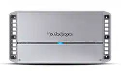
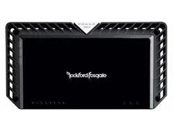
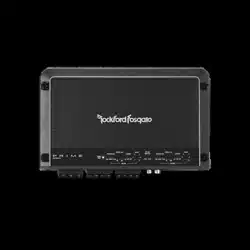
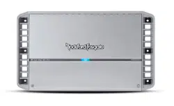
Documents: Go to donwload!
- User Manual - (English)
- User manual - (English)

User Manual for Rockford Fosgate PM600X4
Table of contents
- Introduction
- Specifications
- Design Features
- Installation
- Installation Considerations
- Mounting Locations
- Battery and Charging
- Wiring the System
- Operation
- Clip Indicator Setup
- Adjusting Crossover Frequency
- Channel Switch
- Subwoofer Input Switch
- Infrasonic Filter
- Punch EQ
- Troubleshooting
- Limited Warranty Information
Operation
Input Clip Indicator Setup
- Step 1. Be sure to disconnect all speakers from the amplifier.
CAUTION : Failure to comply may cause damage to connected components and/or amplifier.
- Step 2. Turn on the source unit with volume set to zero.
- Step 3. Adjust the Bass & Treble levels on the source unit to flat.
- Step 4. Download test tones at https://rftech.custhelp.com/app/answers/ detail/a_id/1126/. Scroll to the bottom of the page and download your preferred format.
Note: Use the 40Hz @ 0dB tone (Track 5) for mono amplifier applications or the 1kHz @ 0dB tone (Track 7) for multi-channel amplifier applications. Be sure your x-over is switched to the appropriate filter setting.
- Step 5. Increase the source unit volume until the Input Clip Indicator illuminates red.
Note: Input Clip can be viewed remotely with optional PLC2.
- Step 6. Decrease the source unit volume slightly until the light turns completely off. This establishes your maximum source unit volume for adjusting the Output Clip Indicator.
Note: Some source units will not clip.
Output Clip Indicator Setup
- Step 7. Be sure to disconnect Punch Level Control - PLC (if equipped) from the amplifier.
- Step 8. Adjust the Input Level knob until the Output Clip Indicator illuminates to the appropriate color. Repeat for all channel levels of input.
- Step 9. Turn the source unit volume down.
- Step 10. Reconnect all speakers and Punch Level Control - PLC (if equipped) to the amplifier. Be sure to maintain proper speaker polarity. Operation illus.-3.1 illus.-3.2 illus.-3.3
Adjusting Crossover Frequency
- Do the following individually for each channel.
- Placing the crossover switch in the HP position sets the amplifier to the High Pass mode, enabling frequencies above the cut-off point to pass, adjustable between 50-250Hz.
- Placing the crossover switch in the AP position sets the amplifier to the All Pass mode, preventing any crossover adjustment, allowing all frequencies to pass.
- Placing the crossover switch in the LP position sets the amplifier to the Low Pass mode, enabling frequencies below the cut-off point to pass, adjustable between 50-250Hz.
- Turn the crossover adjustment knob all the way down. With the system playing, turn the crossover adjustment knob up slowly until the desired crossover point is achieved.
Newest Added: PM1000X1BD PMX-HD9813 PS-8 P500-12P TMS57
Also, These documents are for others Rockford Fosgate models: PM300X1, PM300X2, PM400X2, PM400X4, PM500X1BD, PM500X2, PM1000X1BD, PM1000X5
Tags: Rockford Fosgate P500 12, Rockford Fosgate Model Four