Documents: Go to download!
User Manual
- Owner's manual - (English)
- Use And Care Manual - (English)
- Product Comparison - (English)
- Warranty - (English)
- Tax Rebate Certificate - (English)
- Technical Specifications - (English)
User manual of Richmond 6RHE40SP (1 pages)
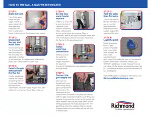
- Installing the water heater
- Care and cleaning of the water heater
- Before You Call For Service
- Gas Control (Thermostat) Status Codes
Table of contents
User Manual Richmond 6G75PV-76PFW Water Heater
Installing the water heater
Location
The water heater should not be located in an area where leakage from the tank or connections will result in damage to the area adjacent to the heater or to lower floors of the structure.
When such areas cannot be avoided it is recommended that a suitable drain pan, adequately drained, must be installed under the water heater.
The water heater must be centered in the drain pan.
The drain pan must not restrict air flow to the combustion air inlet openings (perforation openings) located around the lower perimeter of the water heater.
Drain pan kits are available from the store where the water heater was purchased, or any water heater distributor.
Make certain the floor underneath the water heater is strong enough to sufficiently support the weight of the water heater once it is filled with water.
A gas fired water heater or any other appliance should not be installed in a space where liquids which give off flammable vapors are to be used or stored. Such liquids include gasoline, LP gas (butane or propane), paint or adhesives and their thinners, solvents or removers.
DO NOT block or obstruct any of the combustion air inlet openings located around the perimeter of the water heater. A minimum of 1 in. is required between these combustion air inlet openings and any obstruction.
DO NOT obstruct or block the Flammable Vapor Sensor.
Because of natural air movement in a room or other enclosed space, flammable vapors can be carried some distance from where liquids which give off flammable vapors are to be used or stored. The open flame of the water heater’s main burner can ignite these vapors and create a shutdown condition of the water heater which will not allow the water heater to ignite until examined by a Qualified Service Technician.
FVIR certified gas water heaters can be installed on a residential garage floor without the use of an 18-inch stand in accordance with the National Fuel Gas Code, NFPA 54, ANSI Z223.1, unless otherwise directed by State and Local code requirements. The water heater must be located so it is not subject to physical damage, for example, by moving vehicles, area flooding, etc.
- We recommend this water heater be installed in locations where the ambient temperatures DO NOT exceed 100°F C
IMPORTANT: DO NOT install the water heater in a location where it may be subjected to ambient temperatures exceeding 125°F (52°C).
- The water heater should be installed so as to minimize the length of plastic vent pipe and the number of vent connection fittings required. See the "Venting Section" for vent system requirements.
- Long hot water lines should be insulated to conserve water and energy.
- The water heater and water lines should be protected from exposure to freezing temperatures.
- DO NOT install the water heater in bathrooms, bedrooms, any occupied rooms normally kept closed, or in unprotected outdoor areas.
- Minimum clearance from combustible construction:

If the clearances stated on the Instruction/ Warning Label, located on the front of the heater differ, install the water heater according to the clearances stated on the label.
- If the water heater is installed in an alcove or closet, the entire floor must be covered by a wood or metal panel. A minimum of 24 in. clearance from the front and top should be available for adequate inspection and servicing.
- The water heater may be installed on combustible floors, but not directly on carpeting. If the water heater must be installed on carpeting, place a metal or wood panel beneath the water heater, extending beyond its full width and depth at least 3 in. in all directions.
NOTICE: For proper operation and maintenance, a minimum clearance of 1.5 in. must be provided from the combination temperature and pressure relief valve to any wall or object.
To Fill the Water Heater
Condensation
Gas Supply
The branch gas supply line to the water heater should be clean 1/2 in. black steel pipe or other approved gas piping material.
A union or ANSI design certified semirigid or flexible gas appliance connector should be installed in the gas line close to the water heater. The National Fuel Gas Code (NFGC) mandates a manual gas shut-off valve: See (NFGC) for complete instructions.
If flexible connectors are used, the maximum length shall not exceed 36 in. and must meet the requirements in ANSI Z21.24-Connectors for Gas Appliances.
Compound used on the threaded joints of the gas piping must be of the type resistant to the action of LP gas. Use compound sparingly on male threads only.
Where a sediment trap is not incorporated as part of the appliance, a sediment trap shall be installed downstream of the equipment shutoff valve as close to the inlet of the appliance as practical at the time of the appliance installation. The sediment trap shall be either a tee fitting with a capped nipple in the bottom outlet or other device recognized as an effective sediment trap.
DO NOT use excessive force (over 31.5 ft•lbs.) (42.70 N•m) in tightening the pipe joint at the Combination Gas Control Thermostat) inlet, particularly if Teflon pipe compound is used, as the valve body may be damaged.
The inlet gas pressure to the water heater must not exceed 14 in. w.c. for natural gas, or 14 in. w.c. for LP gas. For purposes of input adjustment, the minimum inlet gas pressure (with main burner on) is shown on the water heater rating plate. If high or low gas pressures are present, contact your gas supplier for correction.
Leak Testing
The water heater and its gas connections must be leak tested at normal operating pressures before it is placed in operation.
- Turn on the manual gas shut-off valve near the water heater.
- Use a soapy water solution to test for leaks at all connections and fittings. Bubbles indicate a gas leak that must be corrected.
The factory connections to the gas control thermostat) should also be leak tested after the water heater is placed in operation.
Pressure Testing the Gas Supply System
The water heater and its individual shutoff valve must be disconnected from the gas supply piping system during any pressure testing of that system at test pressures in excess 1/2 psi (3.5 kPa).
The water heater must be isolated from the gas supply piping system by closing its individual manual gas shutoff valve during any pressure testing of the gas supply at test pressures equal to or less than 1/2 psi (3.5 kPa).
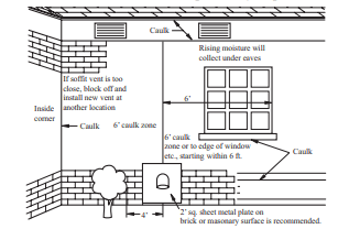
Additional Vent Location Considerations
- DO NOT install the vent terminal under any patio or deck.
- To help prevent moisture from freezing on walls and under eaves, DO NOT locate the vent terminal on the side of a building with prevailing winter winds.
- When terminating the vent pipes through brick or masonry surfaces, the installation of a rust resistant sheet metal backing plates behind the vent terminal is recommended.
- DO NOT locate the vent terminal too close to shrubbery, as flue gasses may damage them.
- Caulk all cracks, seams and joints within 6 ft. of the vent terminal.
- Insulate vent pipe exposed to cold conditions (attics, crawl spaces, etc.) with inflammable material to help prevent moisture from accumulating in the vent pipe.
- Support horizontal sections of the vent pipe every 4 ft. DO NOT rigidly secure the vent system. Provisions must be made to allow for expansion and contraction of the vent system.
- DO NOT install the vent terminal less than 1 ft. above grade or average snowfall whichever is greater.
- Permanently seal annular openings around the vent system penetration using approved materials to prevent entry of combustion products into the building
- DO NOT terminate near soffit vents or crawl space or other area where condensate or vapor could create a nuisance hazard or cause property damage.
- DO NOT locate the exhaust vent terminal where condensate or vapor could cause damage or could be detrimental to the operation of regulators, relief valves, or other equipment.
- DO NOT locate the exhaust vent terminal over public area or walkways where condensate or vapor can cause nuisance or hazard.
- DO NOT locate the vent terminal in proximity to plants/shrubs.
Vertical Vent Terminal Installation
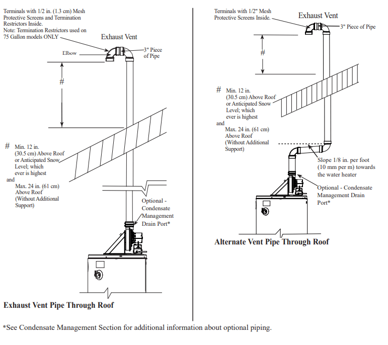
The location of the vent terminal depends on the following minimum clearances and considerations.
- Minimum 12 in. above roof.
- Minimum 12 in. above anticipated snow level.
- Maximum 24 in. above roof level without additional support for vent.
- Four (4) ft. from any gable, dormer or other roof structure with building interior access (i.e., vent, window, etc.).
- Ten (10) ft. from any forced air inlet to the building. Any fresh or make-up air inlet such as a dryer or furnace area is considered to be a forced air inlet.
- Maintain a minimum distance from the vent terminal of not less than 12 in. above grade or average snowfall, whichever is greater.
Read these instructions thoroughly and make sure you understand all steps and procedures before proceeding with the installation.
Determine the locations for the vent terminal then make a hole through the roof and interior ceiling(s) to accommodate the vent pipe.
Assemble the vent pipe assembly.
Install the vent system and attach it to the blower exhaust coupling on the water heater’s blower assembly.
Horizontal lengths of the vent system must slope towards the water heater a minimum of 1/8 in. per foot (10 mm per m).
- Support vertical and horizontal lengths of the vent system as previously mentioned.
Determine the vent terminal height and cut the pipe accordingly.
- Insert lengths of vent pipe through the ceiling wall as shown.
- Install adequate flashing where the vent pipe passes through the roof.
- Place the supplied mesh metal screen inside the vent terminal then connect a short piece of pipe approximately 3 in. between the terminal and elbow.
NOTICE: For cold climates the screen may be removed.
NOTICE: This water heater is supplied with a vent termination restrictor. The restrictor helps the water heater achieve peak efficiency when the water heater is installed using 3 in. diameter pipe at the minimum equivalent vent length of 10 ft.
IMPORTANT: DO NOT install the termination restrictor in equivalent vent lengths longer than 10 ft. or on any other Power Vent model.
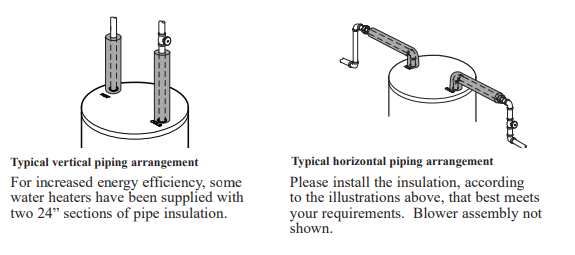
Hot and Cold Pipe Insulation Installation
Heat Traps
For increased energy efficiency, some water heaters have been supplied with factory installed 1 in. NPT heat traps in the hot outlet line and cold water inlet line.
These heat traps may require a minimum of one (1) 90° 1 in. NPT elbow and may require an additional 90° 1 in. NPT elbow or a 1 in. coupling depending on your installation needs. See illustration of nipples and heat traps on pages 36.
Installation Checklist
A. Water Heater Location
- Close to area of vent.
- Drain pan installed.
- Indoors and protected from freezing temperatures.
- Proper clearance from combustible surfaces observed and water heater not installed on carpeted floor.
- Sufficient fresh air supply for proper operation of water heater.
- Air supply free of corrosive elements and flammable vapors.
- Provisions made to protect area from water damage.
- Sufficient room to service heater.
- Combustible materials, such as clothing, cleaning materials, rags, etc. clear of the base of the heater.
- Clearances of 1 in. from combustion air inlet openings observed
- Flammable vapor sensor is not blocked.
B. Water Supply
- Water heater completely filled with water.
- Air purged from water heater and piping.
- Water connections tight and free of leaks.
C. Gas Supply
- Gas line equipped with shut-off valve, union and sediment trap.
- Approved pipe joint compound used.
- Soap and water solution used to check all connections and fittings for possible gas leak.
- Gas Company inspected installation (if required).
D. Relief Valve
- Temperature and Pressure Relief Valve properly installed and discharge line run to open drain.
- Discharge line protected from freezing.
E. Venting
- Water Heater vented separately from all other appliances.
- Flue baffle properly hung in top of heater’s flue.
- Blower assembly properly installed.
- Proper materials and techniques used in the installation of the vent assembly.
- Vent pipe properly secured to blower exhaust coupling on the blower assembly.
- Vent system supported at required intervals.
- Appropriate minimum clearances observed.
- Precautions taken to prevent moisture damage around vent termination.
- Vapors from vent pipe cement and primer have dissipated prior to applying electrical power.
F. Wiring
- Correct power supply (120 V).
- Electrical connections tight.
- Heater properly grounded and proper polarity observed.
Operating Procedure
This heater is equipped with a hot surface ignitor to light the main burner. There is no pilot light to be lit, but on initial startup, it is recommended that the outer door be removed (leave inner door in place for safety) to determine if the hot surface ignitor and main burner are operating properly.
Once filled with water, it is only necessary to plug the power cord in and make sure the
ON/OFF” switch located on the blower assembly is in the “ON” position to put the water heater into operation. Within seconds the hot surface ignitor should heat up, then the gas control (thermostat) should open and the main burner ignite. After the main burner ignites, replace the outer door. If no main burner flame is established, the gas control will go through three trials for ignition before going into a lock-out. A warning light will alert the user of this lock-out condition. If this happens, refer to “Troubleshooting Guide.”
TO SHUT OFF WATER HEATER – Turn switch on the blower assembly to the “OFF” position
Water Temperature Setting
The temperature of the water in the water heater can be regulated by pressing the buttons on the front of the gas control thermostat).
Safety and energy conservation are factors to be considered when selecting the water temperature setting of the water heater’s gas control (thermostat(s)). The lower the temperature setting, the greater the savings in energy and operating costs.
To comply with safety regulations, the gas control (thermostat) was set at its lowest setting before the water heater was shipped from the factory. The recommended starting point temperature is 120°F (49°C).
Water temperatures above 125°F (52°C) can cause severe burns or death from scalding. Be sure to read and follow the warnings outlined in this manual and on the label located on the water heater near the gas control thermostat.
Mixing valves are recommended for reducing point of use water temperature by mixing hot and cold water in branch water lines. It is recommended that a mixing valve complying with the Standard for Temperature Actuated Mixing Valves for Hot Water Distribution Systems, ASSE be installed. See page 4 for more details and contact a licensed plumber or the local plumbing authority for further information.
The chart on the next page may be used as a guide in determining the proper water temperature for your home.
Care and cleaning of the water heater
Draining the Water Heater
Before turning off the cold water supply to the water heater, open a hot water faucet allowing sufficient cold water into the tank to prevent the risk of a scald injury while draining the water heater. Once the water in the tank is no longer hot, turn off the cold water supply to the water heater.
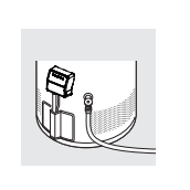
Open a hot water faucet or lift the handle on the relief valve to admit air to the tank. Attach a garden hose to the drain valve on the water heater and direct the stream of water to a drain. Open the valve.
Routine Preventative Maintenance
Inspect dilution air inlet and combustion air inlet openings. Make certain no blockage exists. Clean any lint, dirt or oil accumulation that may exist. Periodically clean the screens in the vent terminal (if applicable).
At least once a year, lift and release the lever handle on the temperature pressure relief valve, located near the top of the water heater, to make certain the valve operates freely. Allow few quarts to be drained through the discharge line to an open drain.
NOTICE: If the temperature and pressure relief valve on the water heater discharges periodically, this may be due to thermal expansion in a closed water system. Contact the water supplier or your plumbing contractor on how to correct this. DO NOT plug the relief valve outlet.
A water heater’s tank can act as a settling basin for solids suspended in the water. It is therefore not uncommon for hard water deposits to accumulate in the bottom of the tank. It is suggested that a few quarts of water be drained from the water heater’s tank every month to clean the tank of these deposits.
Rapid closing of faucets or solenoid valves in automatic water using appliances can cause a banging noise heard in a water pipe. Strategically located risers in the water pipe system or water hammer arresting devices can be used to minimize the problem.
The anode rod should be removed from the water heater’s tank annually for inspection and replaced when more than 6 in. of core wire is exposed at either end of the rod.
Make sure the cold water supply is turned off before removing anode rod.
This water heater incorporates a combustion shut off device that shuts the operation of the water heater down if undesirable combustion conditions occur, such as the presence of flammable vapors or blockage of the combustion air inlet openings. Please contact a Qualified Service Technician if this occurs.
Housekeeping
Visually inspect the hot surface ignitor. To ensure sufficient ventilation and combustion air supply, proper clearances must be maintained.
When installed in a closet, DO NOT block or obstruct any of the combustion air inlet openings located around the perimeter of the water heater. A minimum of 1 in. is required between these combustion air inlet openings and any obstruction.
DO NOT obstruct or block the Flammable Vapor Sensor. The sensor does not require any maintenance or cleaning. DO NOT expose to cleaning agents.
Venting System Inspection
Periodically inspect the vent system. Make certain that all joints are secure and the vent system supports are all in place,
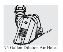
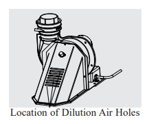
Check the vent system terminal to see that it is free from obstructions and there is no damage nearby caused by condensate. Inspect dilution air holes. Make certain no blockage exists. Clean any lint, dirt or oil accumulation that may exist.
Test for spillage at the dilution air holes after 5 minutes of burner operation. Place a blown out match or candle close to the dilution air holes. The smoke from the candle or match should be drawn into the dilution air holes. If the smoke is pushed away from the dilution air holes, the blower or vent system may be blocked.
Contact qualified service personnel. Periodically clean the screens in the vent terminal (if applicable). In applicable climates, periodically inspect the vent and air-inlet terminals to ensure they are not blocked by snow.
Burner Inspection
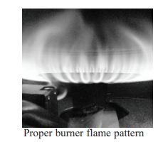
Vacation and Extended Shut-Down
Anode Rod
Before You Call For Service
Condensation
This usually happens when a new water heater is filled for the first time.
- This is normal. After the water in the tank warms a new water heater is up, the condensation will disappear. If, however, the filled for the first time. condition persists, examine the piping and fittings for possible leaks.
Moisture from the products
- This is normal and will disappear in time. Excessive of combustion condensing condensation can cause main burner outage. on the tank surface.
An undersized water
- Use a water heater size that meets the requirements heater will cause of your needs. condensation.
Yellow flame or soot
Scale on top of the burner.
- Contact a qualified service technician to remove scale.
Vent System or Combustion air inlet openings are restricted
- Remove obstruction or debris from vent system or combustion air inlet openings on water heater jacket.
Not enough combustion or ventilation air supplied to the water heater location.
- Proper operation of the water heater requires air for combustion and ventilation. See the Combustion and Ventilation Air information in the “Installing The Water Heater” section of this manual.
Unable to light
Air in gas line.
- Contact a qualified service technician to purge the air the main burner from the gas line.
Blocked Exhaust.
- Contact a qualified service technician to evaluate vent pipe for blockage.
Pressure Switch.
- Make sure the pressure switch hose is not "kinked".
Wire Connections not fully
- Contact a qualified service technician to confirm wire secured. connections.
Combustion Shut-off Device
- Combustion shut-off device should be inspected by a tripped. qualified service technician.
Gas Control Problem.
- Contact a qualified service technician.
Main burner does not stay lit
Gas Controls (Thermostat’s) single use gas shut-off device has opened.
- The gas control (thermostat) should be replaced by a qualified service technician.
Combustion Shutoff Device Tripped.
- The combustion shutoff device should be inspected by a qualified service technician.
Rumbling noise
Scale and sediment
- Drain the water heater to remove scale and sediment from the tank. Refer to the top of page 30.
Relief valve Pressure build up caused by thermal expansion to a closed system.
- This is an unacceptable condition and must be producing popping corrected. Contact the water supplier or plumbing noise or draining contractor on how to correct this. DO NOT plug the relief valve outlet.
Not enough or no hot water
Water usage may have exceeded the capacity of the water heater.
- Wait for the water heater to recover after an abnormal demand.
Low gas pressure.
- Check gas supply pressure and manifold pressure.
The gas control (thermostat) may be set too low.
- See the “Water Temperature Setting” of The Water Heater section of this manual.
Leaking or open hot water faucets.
- Make sure all faucets are closed.
Check valve error codes.
- Refer to gas control (thermostat) status code table on next page.
ON/OFF” switch turned off.
- Turn “ON”.
Blower unplugged.
- Plug in. Verify power supply (120VAC).
Combustion Shutoff System tripped.
- Contact a qualified service technician.
Water is too hot
The gas control (thermostat) is set too high.
- See the “Water Temperature Setting” of The WaterHeater section of this manual.
Gas Control (Thermostat) Defective.
- Contact a qualified service technician to replace the gas control (thermostat).
Gas Control (Thermostat) Status Codes
| LED Status. | Problem | Solution |
|
▼ A B C ● ○ ○ ● ○ ○ |
An open earth ground circuit to the ignition system. |
1. Check that the earth ground connection is properly connected. 2. Check that the ground conductor on the water heater is properly connected. |
|
▼ A B C ● ○ ● ○ ● ○ |
Wiring error or a high resistance to earth ground. |
1. Check proper connection of line neutral and hot wires. 2. Check that the water heater is securely connected to earth ground. |
|
▼ A B C ● ○ ● ○ ○ ○ |
Pressure switch remained closed longer than 5 seconds after the call for heat began. |
1. Pressure switch wiring is incorrect. 2. Replace pressure switch. |
|
▼ A B C ● ○ ● ○ ○ ● |
Pressure switch remained open longer than 5 seconds after the combustion blower was energized. |
1. Pressure switch wiring is incorrect. 2. Pressure switch tubing is not connected correctly. 3. Air intake or exhaust obstructed. |
|
▼ A B C ● ○ ● ○ ● ● |
Error in the hot surface ignitor circuit. |
1. Check that all wiring is correct and secure. 2. Replace hot surface ignitor |
|
▼ A B C ● ○ ○ ● ● ○ |
System in lockout. |
1. Gas supply is off or too low to operate. 2. Hot surface ignitor not positioned correctly. 3. Low voltage to the water heater. 4. Electric polarity to unit is incorrect - test and correct. 5. Combustion shut-off device tripped, contact service agency |
|
▼ A B C ● ○ ○ ○ ● ● |
Problem in the gas control (thermostat) driver circuit. |
1. Turn power to the water heater off for 10 seconds and then back on. 2. Replace gas control valve |
|
▼ A B C ● ○ ● ● ● ○ |
Problem with the internal circuit. |
1. Turn power to the water heater off for 10 seconds and then back on. 2. Replace gas control valve. |
|
▼ A B C ● ● ● ● ● ● |
Problem with the internal circuit. |
1. Turn power to the water heater off for 10 seconds and then back on. 2. Replace gas control valve. |
|
▼ A B C ● ○ ○ ○ ● ○ |
Flame signal sensed out of proper sequence. | 1. Replace gas control valve. |
|
▼ A B C ● ○ ○ ● ● ● |
ECO activated. | 1. Replace gas control valve. |
|
▼ A B C ● ○ ● ● ○ ○ |
One of the temperature adjust buttons stuck closed |
1. Press and release each of the buttons once. 2. Replace gas control valve. |
|
▼ A B C ● ○ ● ● ○ ● |
Water temperature sensor is either open or short circuited. |
1. Check that all wiring is correct and secure. 2. Replace gas control valve. |
|
▼ A B C ● ○ ○ ● ○ ● |
Unit shuts down. |
1. Check for correct wiring to FV sensor. 2. Check for open circuits to FV sensor. 3. Replace FV sensor. |
|
▼ A B C ● ○ ○ ○ ○ ● |
Unit shuts down and in lockout. |
1. FV sensor detected presence of flammable vapors. 2. Contact a service agency |
CAUTION: Label all wires prior to disconnection when servicing controls. Wiring errors can cause improper and dangerous operation. VERIFY PROPER OPERATION AFTER SERVICING.
CAUTION: For your safety DO NOT attempt repair of gas piping, remote control, burners, vent system or other safety devices. Refer repairs to qualified service personnel.
See other models: 6G50PDVP-50 6GDV40PF3 6G50PDVP-40 6G50S-36PE2 6G40S-31PF3
