User Manual
Installing the water heater
This water heater must be installed in accordance with these instructions, local codes, utility company requirements, and/or in the absence of local codes, use the latest edition of the American National Standard/National Fuel Gas Code. A copy can be purchased from either the American Gas Association, 400 N. Capitol Street NW, Washington, DC 20001 as ANSI standard Z223.1 or National Fire Protection Association, 1 Batterymarch Park, Quincy, MA 02269 as booklet NFPA 54.
Combustion and Ventilation Air
Ventilation (ambient) air temperature must be 100°F or less. Proper operation of the water heater requires air for combustion and ventilation. Provisions for combustion and ventilation air must comply with referenced codes and standards.
DO NOT block or obstruct any of the combustion air inlet openings located around the perimeter of the water heater. A minimum of 1” is required between these combustion air inlet openings and any obstruction.
NOTICE: If the water heater is installed in an unconfined space within a building of conventional frame, masonry or metal construction, infiltration air is normally adequate for proper combustion and ventilation. If the water heater is installed in a confined space, provisions for combustion and ventilation air must be made.
DO NOT obstruct or block the Flammable Vapor Sensor.
A confined space is one having a volume of less than 50 cubic feet per 1000 Btuh of the aggregate input of all appliances within that space.
The air must be supplied through two permanent openings of equal area. One is to be located within 12” above the floor and the other is to be located within 12” from the ceiling.
The minimum net free area of each opening must not be less than one square inch per 1000 Btuh of the total input rating of all the appliances in the enclosure (but not less than 100 square inches), if each opening communicates with other unconfined areas inside the building
. Buildings of unusually tight construction shall have the combustion and ventilation air supplied from outdoors, or a freely ventilated attic or crawl space.
If air is supplied from outdoors, directly or through vertical ducts, there must be two openings located as specified above and each must have a minimum net free area of not less than one square inch per 4000 Btuh of the total input rating of all the appliances in the enclosure.
If horizontal ducts are used to communicate with the outdoors, each opening must have a minimum net free area of not less than one square inch per 2000 Btuh of the total input rating of all the appliances in the enclosure. If ducts are used, the minimum dimensions of rectangular air ducts shall not be less than 3”.
NOTICE: If the duct openings which supply combustion and ventilation air are to be covered with a protective screen or grill, the net free area (openings in the material) of the covering material must be used in determining the size of the openings. Protective screening for the openings MUST NOT be smaller than 1/4”mesh to prevent clogging by lint or other debris.
Corrosive Atmospheres
The air in beauty shops, dry cleaning establishments, photo processing labs, and storage areas for liquid and powdered bleaches or swimming pool chemicals often contain such halogenated hydrocarbons.
An air supply containing halogenated hydrocarbons may be safe to breathe, but when it passes through a gas flame corrosive elements are released that will shorten the life of any gas burning appliance.
Propellants from common spray cans or gas leaks from A/C and refrigeration equipment are highly corrosive after passing through a flame.
The water heater warranty is voided when failure of the heater is due to operation in a corrosive atmosphere.
Typical Installation
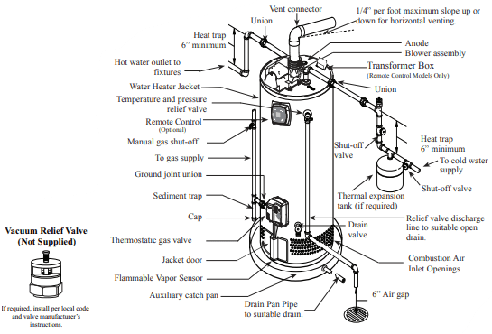
NOTICE: The National Fuel Gas Code (NFGC) mandates a manual gas shut-off valve: See (NFGC) for complete instructions. Local codes or plumbing authority requirements may vary from the instructions or diagrams provided and take precedent over these instructions.
A new combination temperature and pressure relief valve, complying with the Standard for Relief Valves and Automatic Gas Shut-Off Devices for Hot Water Supply Systems, ANSI Z21.22, is supplied and must remain in the opening provided and marked for the purpose on the water heater. No valve of any type should be installed between the relief valve and the tank. Local codes shall govern the installation of relief valves.
Relief Valve
The pressure rating of the relief valve must not exceed 150 PSI, the maximum working pressure of the water heater as marked on the rating plate. The Btuh rating of the relief valve must equal or exceed the Btuh input of the water heater as marked on its rating plate. Position the outlet of the relief valve above a suitable open drain to eliminate potential water damage. Piping used should be of a type approved for hot water distribution. The discharge line must be no smaller than the outlet of the valve and must pitch downward from the valve to allow complete drainage (by gravity) of the relief valve and discharge line. The end of the discharge line should not be threaded or concealed and should be protected from freezing. No valve of any type, restriction, or reducer coupling should be installed in the discharge line.
To Fill the Water Heater
Make certain that the drain valve is closed, then open the shut-off valve in the cold water supply line. Open each hot water faucet slowly to allow the air to vent from the water heater and piping. A steady flow of water from the hot water faucet(s) indicates a full water heater. Do not allow the flammable vapor sensor to become submerged in water.
Condensation
Condensation can form on the tank when it is first filled with water. Condensation might also occur with a heavy water draw and very cold inlet water temperatures. Drops of water falling on the burner can produce a sizzling or pinging sound. This condition is not unusual, and will disappear after the water becomes heated. If, however, the condensation continues, examine the piping and fittings for possible leaks.
Gas Supply
The branch gas supply line to the water heater should be clean 1/2” black steel pipe or other approved gas piping material.
A ground joint union or ANSI design certified semi-rigid or flexible gas appliance connector should be installed in the gas line close to the water heater. The National Fuel Gas Code (NFGC) mandates a manual gas shut-off valve: See (NFGC) for complete instructions.
If flexible connectors are used, the maximum length shall not exceed 36” and must meet the requirements in ANSI Z21.24-Connectors for Gas Appliances.
If lever type gas shut-offs are used, they shall be T-Handle type.
Compound used on the threaded joints of the gas piping must be of the type resistant to the action of LP gas. Use compound sparingly on male threads only.
Where a sediment trap is not incorporated as part of the appliance, a sediment trap shall be installed downstream of the equipment shutoff valve as close to the inlet of the appliance as practical at the time of the appliance installation. The sediment trap shall be either a tee fitting with a capped nipple in the bottom outlet or other device recognized as an effective sediment trap.
Do not use excessive force (over 31.5 ft lbs.) in tightening the pipe joint at the gas control (thermostat) inlet, particularly if teflon pipe compound is used, as the valve body may be damaged.
The inlet gas pressure to the water heater must not exceed 10.5” w.c. for natural gas, or 14” w.c. for LP gas. For purposes of input adjustment, the minimum inlet gas pressure (with main burner on) is shown on the water heater rating plate. If high or low gas pressures are present, contact your gas supplier for correction.
Leak Testing
The water heater and its gas connections must be leak tested at normal operating pressures before it is placed in operation.
- Turn on the manual gas shut-off valve near the water heater.
- Use a soapy water solution to test for leaks at all connections and fittings. Bubbles indicate a gas leak that must be corrected.
The factory connections to the gas control (thermostat) should also be leak tested after the water heater is placed in operation.
Pressure Testing the Gas Supply System
The water heater and its manual gas shut-off valve must be disconnected from the gas supply piping system during any pressure testing of that system at pressures in excess of 3/8 psi (10.5” w.c.) for natural gas, or 1/2 psi (14” w.c.) for LP gas. The water heater must be isolated from the gas piping system by closing the manual gas shut-off valve during any pressure testing of the gas supply piping at pressures equal to or less than 3/8 psi (10.5” w.c.) for natural gas, or 1/2 psi (14” w.c.) for LP gas.
High Altitude
Input rating of this water heater is based on sea level operation. At higher elevations the actual input rate may be lower than the value listed on the rating label due to the derating of natural gas and LP gas. This water heater can be installed at elevation up to 2,000 feet without any change or modification.
For installation between 2,000 and 7,700 feet, refer to the Venting Information tables on page 13 and 14 for maximum vent lengths.
Installations above 7,700 feet are not authorized.
Contact the local gas supplier for more information.
Venting
The water heater must be vented to the outdoors as described in these instructions. DO NOT connect this water heater to an existing vent or chimney - it must be vented separately from all other appliances.
NOTICE: This unit can be vented using only the following recommended pipe material. Use only 2- or 3-inch diameter pipe.
PVC (Schedule 40, ASTM D1785)
CPVC (Schedule 40, ASTM F441)
ABS (Schedule 40, ASTM D2661)
ABS (Schedule 40 DWV, Cellular Core, ASTM F628)
The fittings, other than the TERMINATION, should be equivalent to the following:
PVC (Schedule 40 DWV, ASTM D2665)
CPVC (Schedule 40, ASTM F438)
ABS (Schedule 40 DWV, ASTM D2661)
The unit may be vented horizontally through a wall or vertically through the roof. Vent pipe runs must be adequately supported along both vertical and horizontal lengths. Maximum unsupported length is recommended to be no more than 6 feet. It is imperative that the first hanger be located on the horizontal length immediately adjacent to the first 90-degree elbow from the vertical rise of vent pipe connected to the water heater. The support method used should isolate the vent pipe from floor joists or other structural members to help prevent the transmission of noise and vibration. Do not support, pin or otherwise secure the venting system in a way that restricts the normal thermal expansion and contraction of the chosen venting material. If the water heater is being installed as a replacement for an existing power vented water heater, a thorough inspection of the existing venting system must be performed prior to any installation work.
- Verify that the correct materials as detailed above have been used, and that the minimum or maximum vent length and terminal locations as detailed in this manual have been met.
- Carefully inspect the entire venting system for any signs of cracks or fractures, particularly at the joints between elbows or other fittings and the straight length of vent pipe.
- Check the system for signs of sagging or other stresses in the joints as a result of misalignment of any components in the system.
- If any of these conditions are found, they must be corrected in accordance with the venting instructions in this manual before completing the installation and putting the water heater into service.
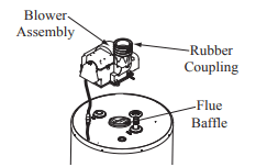
NOTICE: The vent piping must be connected to the blower assembly using the rubber coupling and supplied clamps. The vent pipe connections at the blower assembly must be leak tested with soap and water solution upon initial startup. Repair any leaks before allowing the water heater to operate.
Additional installation information for The Commonwealth of Massachusetts is located on the back page of this manual.
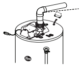
Blower Assembly Installation
Connect blower assembly with the electrical connector. Attach Blower Assembly to top pan using the six (6) screws provided (See diagram to the left). Install rubber coupling (supplied in the box with water heater) on blower housing and secure it. Do not overtighten screws to ensure plastic does not crack.
NOTICE: The Blower Assembly is model specific and only the blower assembly supplied should be used on this water heater.
Maximum and Minimum Vent Lengths for Residential 40 & 50 Gallon Power Vents
Minimum vent length for 2”vent pipe is one (1) foot (30.4 cm)of vertical pipe, one (1) 90°elbow, and three (3) feet (0.91 m) of horizontal pipe.
Maximum Venting information for 2” Vents*
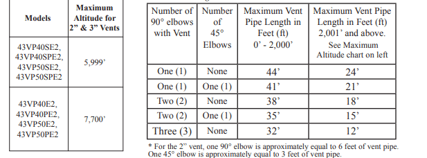
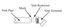
Minimum vent length for 3” vent pipe is one (1) foot of vertical pipe, one (1) 90°elbow, and four (4) feet of horizontal pipe.
Maximum Venting information for 3” Vents**
NOTICE: The mixing of 2" and 3" vent pipe is not recommended. If 3" pipe is used, a 2" to 3" reducer fitting is recommended at the rubber coupling.
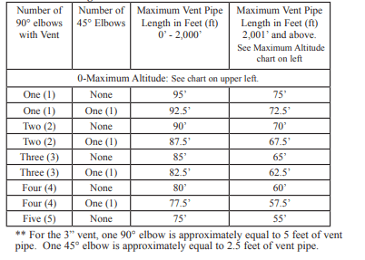
Minimum Vent Restrictor
Install.the.vent.restrictor.at.the.minimum.vent.lengths. listed.above .
DO NOT use.the.vent.restrictor.for.any.other.vent. lengths
NOTICE: All pipe, fittings, solvent cement, primers and procedures must conform to American National Standards Institute and American Society for Testing and Materials (ANSI/ASTM) standards
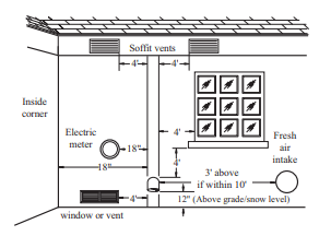
Horizontal Vent Terminal Location
The location of the vent terminal depends on the following minimum clearances and considerations (see illustration):
- Vent Terminal must be at least twelve (12) inches above grade level and above normal snow levels.
- Vent Terminal must be at least four (4) feet below, or four (4) feet horizontally from any door, operable window, soffit, under eave vent or gravity air inlet to the building or other appliances, or from gas or electric meters. Do not locate vent above walkways, doors, windows, air inlets, gas or electric meters or other equipment.
- Vent Terminal must be at least three (3) feet above any forced air inlet located within ten (10) feet. Any fresh or make-up air inlet such as for a dryer or furnace area is considered to be a forced air inlet.
- Vent Terminal must be at least eighteen (18) inches from an inside corner formed by two exterior walls.
Additional Considerations
- Do Not install vent terminal under any patio or deck.
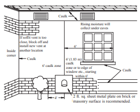
- To help prevent moisture from freezing on walls and under eaves, do not locate vent terminal on the side of a building with prevailing winter winds.
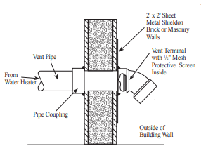
- When terminating the vent pipe through brick or masonry surfaces, a rust-resistant sheet metal backing plate behind the vent termination is recommended.(See illustration.)
- Do Not locate vent terminal too close to shrubbery, as flue gasses may damage them.
- Caulk all cracks, seams and joints within six (6) feet of vent terminal.
- All painted surfaces should be primed to lessen the chance of physical damage. Painted surfaces will require maintenance.
- Insulate vent pipe exposed to cold conditions (attics, crawl spaces, etc.) with inflammable material to help prevent moisture from accumulating in vent pipe.
- Do Not extend exposed vent pipe outside of building.
NOTICE: All pipe, fittings, solvent cement, primers and procedures must conform to American National Standards Institute and American Society for Testing and Materials (ANSI/ASTM) standards.
Horizontal Vent Installation
Once the vent terminal location has been determined, make a hole through the exterior wall to accommodate the vent pipe. Vent pipe must exit exterior wall horizontally only.
Insert a small length of vent pipe through the wall and connect the coupling as shown to the left.
Place the 1/2" mesh metal screen inside the terminal fitting and connect it as shown to the vent pipe on the exterior of the building.
Complete the rest of the vent pipe installation to the water heater's vent connector fitting on the blower outlet.
If necessary support horizontal run as previously mentioned.
Vertical Vent Termination Location
The location of the vent terminal depends on the following minimum clearances and considerations (see illustration):
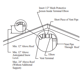
- Minimum twelve (12) inches above roof.
- Minimum twelve (12) inches above anticipated snow level.
- Maximum twenty-four (24) inches above roof level without additional support for vent.
- Four (4) feet from any gable, dormer or other roof structure with building interior access (i.e., vent, window, etc.).
- Ten (10) feet from any forced air inlet to the building. Any fresh or make-up air inlet such as a dryer or furnace area is considered to be a forced air inlet.
Vertical Vent Installation
Once the vent terminal location has been determined, make a hole through the roof and interior ceiling to accommodate the vent pipe.
Complete the vent pipe installation to the water heater's vent connector fitting on the blower outlet.
Support vertical or horizontal lengths as previously mentioned.
Install adequate flashing where the vent pipe passes through the roof.
Determine the vent terminal height and cut vent pipe accordingly. Refer to the above section for proper vent terminal height.
Connect vent elbow onto vertical pipe through roof.
Connect short piece of vent pipe(approximately 3" long) to elbow, then insert 1/2" mesh metal screen into terminal elbow and join it to the short piece of vent pipe.
Cementing Joints
All joints in the vent piping must be properly sealed and the following materials are recommended:
PVC materials should use ASTM D2564 grade cement.
CPVC materials should use ASTM F493 grade cement.
ABS materials should use ASTM D2235 grade cement.
Cleaner-Primer and Medium Body Solvent Cement:
- Cut pipe end square, remove jagged edges and burrs. Chamfer end of pipe, then clean fitting socket and pipe joint area of all dirt, grease or moisture.
- After checking pipe and socket for proper fit, wipe socket and pipe with cleaner-primer. Apply a liberal coat of primer to inside surface of socket and outside of pipe. Do not allow primer to dry before applying cement.
- Apply a thin coat of cement evenly in the socket. Quickly apply a heavy coat of cement to the pipe end and insert pipe into fitting with a slight twisting motion until it bottoms out. NOTICE: Cement must be fluid; if not, recoat.
- Hold the pipe fitting for 30 seconds to prevent the tapered socket from pushing the pipe out of the fitting.
- Wipe all excess cement from the joint with a rag. Allow 15 minutes before handling. Cure time will vary according to fit, temperature and humidity.
NOTICE: Stir the solvent cement frequently while using. Use a natural bristle brush or the dauber supplied with the can. The proper brush size is one inch.
NOTICE: This unit is equipped with a Flammable Vapor Sensor. Do not apply power until enough time has passed to allow the vapors from the primer and cement to dissipate.
Wiring
If local codes permit, the water heater may be connected to electric service with the power cord provided (DO NOT use an extension cord). A grounding receptacle is required.
If local codes do not permit the use of cord connections, a 120 V, 50/60 Hz power supply, with suitable disconnecting means, must be connected to the black and white leads in the heater control enclosure.
A knock-out hole is provided to permit use of conduit or metal-clad cable connectors.
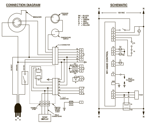
The maximum current draw is approximately 5.0 amps. The water heater must be electrically grounded in accordance with local codes, or, in the absence of local codes, in accordance with latest edition of the National Electric Code ANSI/NFPA No. 70. Refer to the figures below for water heater internal wiring.
NOTE: It is not recommended that this unit be installed on a GFCI circuit.
Diagram Without Optional Electronic Display
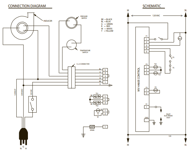
Diagram With Optional Electronic Display
Insulation Blankets
Insulation blankets, available to the general public, for external use on gas water heaters are not necessary. The purpose of an insulation blanket is to reduce the standby heat loss encountered with storage tank heaters. This water heater meets or exceeds the NationalAppliance Energy Conservation Act standards with respect to insulation and standby loss requirements making an insulation blanket unnecessary.
The manufacturer’s warranty does not cover any damage or defect caused by installation, attachment or use of any type of energy saving or other unapproved devices (other than those authorized by the manufacturer) into, onto or in conjunction with the water heater. The use of unauthorized energy saving devices may shorten the life of the water heater and may endanger life and property.
The manufacturer disclaims any responsibility for such loss or injury resulting from the use of such unauthorized devices.
CAUTION: If local codes require the application of an external insulation blanket to this water heater, pay careful attention to the following so as not to restrict the proper function and operation of the water heater:
- Do not cover the operating or warning labels attached to the water heater or attempt to relocate them on the exterior of insulation blanket.
- Do not apply insulation to the top of the water heater. This will interfere with the safe operation of the blower assembly.
- Do not cover the burner access door, jacket door, gas control (thermostat)/gas valve or pressure and temperature relief valve.
- Do not apply insulation to the bottom of the water heater or the area where the combustion air inlet openings andFlammable Vapor Sensor are located. This area must be unobstructed so as not to restrict combustion air flow to the burner or operation of the sensor.
Inspect the insulation blanket frequently making certain it has not sagged and it is not restricting the air flow to the combustion air inlet openings(perforation holes) or the FlammableVapor sensor located around the lower perimeter of the water heater jacket. This could result in an unsafe operating condition.
Hot and Cold Pipe Insulation Installation
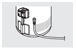
For increased energy efficiency, some water heaters have been supplied with two 24” sections of pipe insulation.
Please install the insulation, according to the illustrations above, that best meets your requirements.
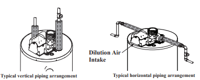
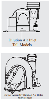
NOTICE: If pipe insulation is used, ensure that the thickness does not exceed ½”. Insulation thicker than ½” can interfere with the Blower Assembly Dilution Air Holes.
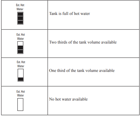
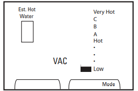
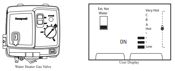
Estimated Hot Water
Three bars shown on the user display are an estimate of hot water available relative to the temperature setpoint. The chart below describes what each symbol means.
Vacation Mode
The user display features a vacation mode which sets the water heater temperature to Low. The user display toggles between On and Vacation Modes when “Mode” key is pressed. Note that the Estimated Hot Water symbol shows no hot water available when in VAC mode. To return the water heater to normal “ON” mode, unlock the display and press the Mode button.
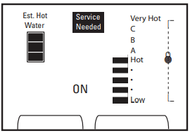
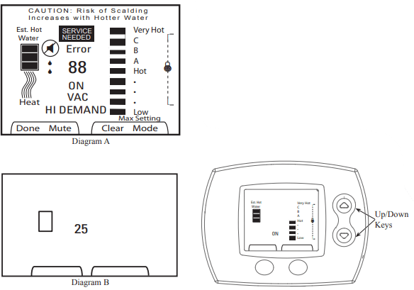
Error Display
When an error message is received from the water heater, the "SERVICE NEEDED" icon flashes. See the screen example below. Call your water heater contractor.
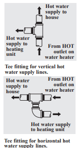
Heat Traps
For increased energy efficiency, some water heaters have been supplied with factory installed 3/4” NPT heat traps in the hot outlet line and cold water inlet line. These heat traps may require a minimum of one (1) 90° 3/4” NPT elbow and may require an additional 90° 3/4” NPT elbow or a 3/4” coupling depending on your installation needs. See Illustration of nipples and heat traps
Installing the Optional User Display
This PowerVent water heater contains an accessory kit for installing the User Display. User Display Mounting Kit – AS42461
a. Optional Water Heater Mounting Bracket – AP14752
b. 12 feet, 18 AWG Thermostat Wire – AP14820
c. Optional Mounting Tape – AP14819
d. Transformer Enclosure – AP14875
e. Screw, #8 x ½" Self Drilling Qty 2 AP5925GS
f. User Display – AP14697
Installation Instructions:
CAUTION: Turn the switch on the blower to the “off” position and disconnect power to the water heater before proceeding!
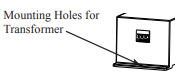
1. Locate the electrical connection for the Transformer Enclosure on the top of the water heater. This electrical connection features a white 6-pin plug and white heat shrink.
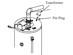
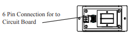
2. The Transformer Enclosure features a 6-pin connection located on the circuit board inside the enclosure. Attach the top pan harness connector to this 6-pin connector in the correct orientation.
3. Locate the two screw pilot holes on the water heater top to attach the Transformer Enclosure to the top pan. Position the enclosure so the terminal strip opening is visible from the front of the water heater. Secure enclosure to top pan with screws provided in the User Display Mounting Kit without pinching any wires.
NOTICE: Do not over tighten to avoid cracking plastic enclosure.
4. Determine where the User Display will be located. The display can be attached to the water heater jacket with supplied Water Heater Mounting Bracket or mounted remotely to a wall via the wall plate up to 100 feet away using 18 AWG solid copper thermostat wire. Any installation location over 12 feet from the water heater will require additional thermostat wire. (Not supplied.)
5. If remote mounting, go to step 19.
6. Cut enough thermostat wire from the 12 feet provided to connect the front mounted display to the Transformer Enclosure located on the top pan.
7. Strip ½” insulation from the 3 wires on both ends. The wire provided is standard 3-wire with the colors GREEN, RED and WHITE.
8. Connect one end of the wire to the Transformer Enclosure spring terminal strip. From left to right colors shall be GREEN – RED – WHITE. Wires should easily insert into the terminal strip. If required for wire insertion or removal, use small flat blade screw driver to press the tab located below each wire hole.
9. Remove two strips of Display Mounting Tape and attach to the inside flanges of the Water Heater Mounting Bracket.
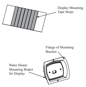
11. The Water Heater Mounting Bracket features a wiring slot on the top flange and an opening for the wire. Pass the thermostat wire though the Water Heater Mounting Bracket opening.
12. Clean any dust or dirt from water heater jacket to allow proper tape adhesion.
13. Remove tape backing and carefully attach to the heater jacket above the Rheem logo. Allow the thermostat wire to be positioned in the wire slot located on the bracket top flange.
14. The User Display will be mounted to the plastic Water Heater Mounting Bracket.
15. Separate wall plate from the User Display by removing battery cover and carefully pull wall plate from display.
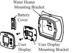
NOTICE: The battery backup option is not available on this model.
16. Replace battery cover.
17. Attach display wall plate to heater bracket using the two #6 x ½” Type A screws provided in User Display Mounting Kit. Wire should pass through display wall plate opening.
18. GO TO STEP 27.
19. Remote mounting will not require the Display to Heater Bracket or Display Mounting Tape. The bracket may be kept for future use or recycled.
20. Choose mounting location and route thermostat wire to this location.
21. Separate wall plate from the User Display by removing battery cover and carefully pull wall plate from display.
22. Replace battery cover.
23. Pass thermostat wire through wire hole in wall plate.
24. Use mounting holes on wall plate to mark wall hole locations.
25. Drill 3/16” holes and install wall anchors if required.
26. Use two #6 x 1” Type A screws provided in the User Display box to attach wall plate to surface.
27. Connect thermostat wire to wall plate as follows:
- Top Terminal - GREEN - Data Communication
- Middle Terminal - RED - Power
- Bottom Terminal - WHITE - Common
28. Attach Thermostat Display to wall plate.
ATTENTION: Leave peel off screen protector on the User Display for customer to review and remove.
29. Connect power to water heater
30. Turn on water heater and allow to heat.
31. Check thermostat display for proper display and function.
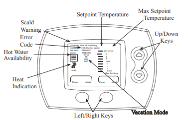
User Display Features
Your water heater includes a user display for easy local or remote water heater programming. The user display features:
- Water heater temperature setpoint control
- Large, clear, backlit display is easy to read even in the dark
- Displays relative available hot water
- Service needed indicator.
Water Heater Optional User Display - Operation Instructions
Display Temperature Setting Limits
After power on, all segments on the LCD will be displayed for 2 seconds, (See Diagram A) followed by software revision shown for 2 seconds (See Diagram B).
User Mode is entered after all required data is received from the appliance when powered-up. The display shows temperature setpoint, estimated amount of hot water and maximum temperature setpoint. Heat symbol is turned on when heating cycle is active. Scald warning starts flashing whenever the adjusted setpoint exceeds the “Hot” setting and becomes solid after 30 seconds of flashing.
Unlocking the User Display
The user display includes a display lock that will prevent accidental adjustments to the water heater. To unlock the display, hold down the UP and DOWN arrow buttons until the lock icon flashes and disappears. The display can now be adjusted. The display will automatically relock if no button presses are detected within a 60 second period.
Display Temperature Setting
Water heater setpoint temperature is shown using vertical bars on the display. The more bars shown the higher the setpoint temperature. Use the UP or DOWN arrows to select the desired setpoint temperature. The top bar indicates the water heater setpoint. The picture below shows a setpoint of “A”.
Notice: When the temperature is set above "HOT", the display will show the "Risk of Scalding Caution".
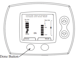
When the desired setpoint is shown on the display, press the "Done" button below the display. The user display will then lock to prevent accidental adjustments.
Display Temperature Setting Limits
The user display setpoint temperature cannot exceed maximum water heater valve setpoint temperature at any time. Max Setting icon appears when the user display setpoint exceeds the water heater gas valve knob setpoint.
The water heater gas valve knob below is set to HOT there fore the user display shows Hot as the maximum available setpoint. The customer in this example has chosen to set the temperature to Hot. When the user display is set to the maximum available setpoint, the Max Setting message will appear on the user display.
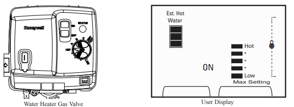
The water heater gas valve knob below is set to VERY HOT therefore the user display shows Very Hot as the maximum available setpoint. The customer in this example has chosen to set the temperature between Low and Hot. With this gas valve knob setting, the full range of temperature setpoints is available at the user display. See Figure on left below.
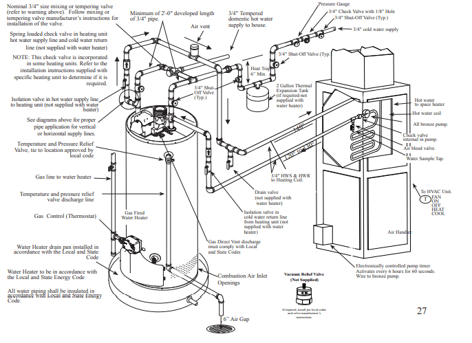
Supplemental instructions for gas water heaters installed in potable water/space heating applications.
Local codes or plumbing authority requirements may vary from the instructions or diagrams provided in this manual and take precedent over these instructions.
Combination Potable Water and Space Heating Application
Tee fitting must be installed as shown. This ensures that any air in the water lines will be purged through the domestic water faucets and showers.
Notice: 50' - 0" maximum distance from water heater to fan coil (developed length) is required for Massachusetts State.
Typical Piping Diagram for Combination Potable/Space Heating Installation
Operating the water heater.
Safety Precautions
- Do turn off manual gas shut-off valve if water heater has been subjected to over heating, fire, flood, physical damage or if the gas supply fails to shut off.
- Do Not turn on water heater unless it is completely filled with water.
- Do Not turn on water heater if cold water supply shut-off valve is closed.
- Do Not allow combustible materials such as newspaper, rags or mops to accumulate near water heater.
- Do Not store or use gasoline or other flammable vapors and liquids, such as adhesives or paint thinner, in vicinity of this or any other appliance. If such flammables must be used, open doors and windows for ventilation, and all gas burning appliances in the vicinity should be shut off including their pilot burners, to avoid vapors lighting.
- If there is any difficulty in understanding or following the Operating Instructions or the Care and Cleaning section, it is recommended that a qualified person or serviceman perform the work.
NOTICE: Flammable vapors can be drawn by air currents from surrounding areas to the water heater.
Operating Procedure
This heater is equipped with an electronically lit pilot to light the main burner. The pilot is automatically lit each time there is a demand for heating the water. On initial start-up, it is recommended that the outer door be removed (leave inner door in place for safety) to determine if the pilot and main burner are operating properly. Once filled with water, it is necessary to plug the power cord in and make sure the “ON/OFF” switch located on the blower assembly is in the “ON” position and the gas control switch is in the “ON” position. The blower will start and within seconds the pilot will light followed by the main burner. After the main burner ignites, replace the outer door.
If no main burner flame is established, the gas control will go through three trials for ignition before going into a lock-out. A warning light will alert the user of this lock-out condition. If this happens, refer to “Troubleshooting Guide.”
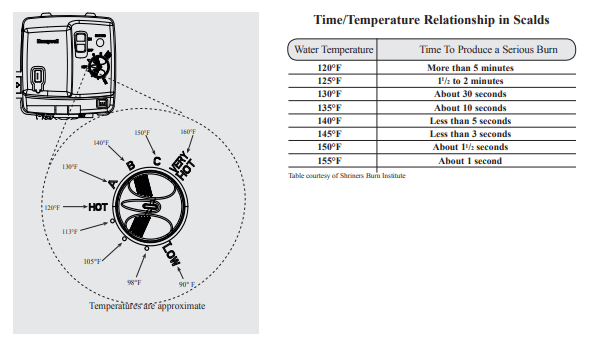
Water Temperature Setting
The temperature of the water in the water heater can be regulated by turning the knob on the front of the gas control (thermostat). Safety and energy conservation are factors to be considered when selecting the water temperature setting of the water heater’s gas control (thermostat(s)). The lower the temperature setting, the greater the savings in energy and operating costs.
To comply with safety regulations, the gas control (thermostat) was set at 120°F before the water heater was shipped from the factory. The recommended starting point temperature is 120°F.
Water temperatures above 125°F can cause severe burns or death from scalding. Be sure to read and follow the warnings outlined in this manual and on the label located on the water heater near the gas control thermostat.
Mixing valves are available for reducing point of use water temperature by mixing hot and cold water in branch water lines. Contact a licensed plumber or the local plumbing authority for further information.
The chart on the next page may be used as a guide in determining the proper water temperature for your home.
The following is additional information which aid in deter�mining a safe working temperature to meet each household need.
Maximum water temperatures occur just after the burner has shut off. To determine the water temperature, turn on a hot water faucet and place a thermometer in the water stream. If an adjustment to the water temperature is pre�ferred, then refer to the Water Heater User Display – Opera�tion Instructions for instruction on adjusting the local and remote user display temperature setpoints.
A condition known as “stacking” or “layering” can occur when a series of short and frequent hot water draws are taken. The hottest temperature water will be at the top of the tank, closest to the outlet pipe delivering hot water to the home.
Stacking can cause this top layer of water to be hatter than the water toward the bottom of the tank near the gas control(thermostat). Therefore, always remember to test the water temperature with your hand before use and remember that hotter water increases the risk of scald injury.
Also, always supervise young children or others who are incapacitated.
The gas control (thermostat) is constructed with a built in safety shut-off device designed to shut off the gas supply to the burner if the main burner is extinguished for any reason.The gas control (thermostat) is also equipped with a gas shut off device that will shut off the gas supply to the burn�er if the water heater exceeds normal operating tempera�tures. Refer to the “Before You Call For Service” section of this manual, or contact your dealer.
WARNING: Should overheating occur or the gas supply fail to shut off, turn off the manual gas control valve to the appliance
If the water heater has been subjected to fire, flood or physi�cal damage, turn off the manual gas control (shut-off) valve and do not operate the water heater again until it has been checked by a qualified service technician.
NOTICE: Replace any part of the gas control system which has been under water.
Care and cleaning of the water heater.
Draining the Water Heater
CAUTION: Shut off gas to the water heater at the gas control (thermostat) gas cock or manual shut-off valve before draining water.
DANGER: Before manually operating the temperature and pressure relief valve, make certain no one will be exposed to the hot water released by the valve. The water drained from the tank may be hot enough to present a scald hazard and should be directed to a suitable drain to prevent injury or damage.
Before turning off the cold water supply to the water heater, open a hot water faucet allowing sufficient cold water into the tank to prevent the risk of a scald injury while draining the water heater. Once the water in the tank is no longer hot, turn off the cold water supply to the water heater. Open a hot water faucet or lift the handle on the relief valve to admit air to the tank.
Attach a garden hose to the drain valve on the water heater and direct the stream of water to a drain. Open the valve.
Routine Preventative Maintenance
Properly maintained, your water heater will provide years of dependable trouble�free service.
It is recommended that a periodic inspection of the gas control (thermostat), burner, relief valve, internal flue-way and venting system should be made by service personnel qualified in gas appliance repair.
It is suggested that a routine preventative maintenance program be established and followed by the user.
Inspect plastic vent pipe. Make certain that all joints are secure and that vent pipe supports are all in place. Check the outdoor vent terminal to see that it is free of obstructions, and that there is no damage nearby casused by condensate.
Inspect dilution air inlet and combustion air inlet openings. Make certain no blockage exists. Clean any lint, dirt or oil accumulation that may exist.
At least once a year, lift and release the lever handle on the temperature pressure relief valve, located near the top of the water heater, to make certain the valve operates freely. Allow several gallons to flush through the discharge line to an open drain.
NOTICE: If the temperature and pressure relief valve on the water heater discharges periodically, this may be due to thermal expansion in a closed water system.
Contact the water supplier or your plumbing contractor on how to correct this.
DO NOT plug the relief valve outlet.
A water heater’s tank can act as a settling basin for solids suspended in the water.
It is therefore not uncommon for hard water deposits to accumulate in the bottom of the tank. If allowed to accumulate, these solids can cover the gas control (thermostat) sensors, causing the sensors to operate erratically. Because accumulated solids can prevent the gas control (thermostat) sensors from accurately reading the water temperature, the water at the fixture can be hotter than the gas control (thermostat) setting. It is suggested that a few quarts of water be drained from the water heater’s tank every month to clean the tank of these deposits.
Rapid closing of faucets or solenoid valves in automatic water using appliances can cause a banging noise heard in a water pipe. Strategically located risers in the water pipe system or water hammer arresting devices can be used to minimize the problem.
The anode rod should be removed from the water heater’s tank annually for inspection and replaced when more than 6” of core wire is exposed at either end of the rod.
Make sure the cold water supply is turned off before removing anode rod.
This water heater incorporates a combustion shut off device that shuts the operation of the water heater down if undesirable combustion conditions occur, such as the presence of flammable vapors or blockage of the combustion air inlet openings. Please contact a Qualified Service Technician if this occurs.
Housekeeping
Visually inspect the pilot. To ensure sufficient ventilation and combustion air supply, proper clearances must be maintained. When installed in a closet, DO NOT block or obstruct any of the combustion air inlet openings located around the perimeter of the water heater. A minimum of 1” is required between these combustion air inlet openings and any obstruction. DO NOT obstruct or block the Flammable Vapor Sensor. The sensor does not require any maintenance or cleaning. DO NOT expose to cleaning agents.
Venting System Inspection
The water heater’s internal flue must be inspected annually to be certain it is clean by removing the blower assembly and flue baffle. When reinstalling the flue baffle make certain it is hung securely by its hanger at the top of the flue way. Reinstall the blower assembly.
Inspect plastic vent pipe. Make certain that all joints are secure and that vent pipe supports are all in place. Check the outdoor vent terminal to see that it is free of obstructions, and that there is no damage nearby caused by condensate. Inspect dilution air holes. Make certain no blockage exists. Clean any lint, dirt or oil accumulation that may exist.
Test for spillage at the dilution air holes after 5 minutes of burner operation. Place a blown out match or candle close to the dilution are holes. The smoke from the candle or match should be drawn into the dilution air holes. If the smoke is pushed away from the dilution air holes, the blower or vent system may be blocked. Contact qualified service personnel
Burner Inspection
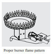
Visually inspect the pilot flame and main burner annually.
Through the sight glass, inspect the pilot and burner lighting. If any unusual pilot or burner operation is noted, the water heater should be shut off until qualified service assistance can be obtained.
CAUTION: For your safety, cleaning of the burner must be performed only by qualified service personnel, as it involves the disconnection of gas piping and leak testing. The burner chamber is a sealed area. If the burner access door is removed, the burner access door gasket must be replaced.
For cleaning, remove the burner from the water heater. A vacuum cleaner can be used on the burner and floor shield inside the water heater. The burner can also be cleaned by scrubbing with mild detergent
Vacation and Extended Shut-Down
If the water heater is to remain idle for an extended period of time, the power and water to the appliance should be turned off to conserve energy and prevent a build-up of dangerous hydrogen gas.
The water heater and piping should be drained if they might be subjected to freezing temperatures.
After a long shut-down period, the water heater’s operation and controls should be checked by qualified service personnel. Make certain the water heater is completely filled again before placing it in operation.
NOTICE: Refer to the Hydrogen Gas Caution in the Operating Instructions.
Anode Rod
This water heater is equipped with an anode rod designed to prolong the life of the glass lined tank. The anode rod is slowly consumed, thereby eliminating or minimizing corrosion of the glass lined tank.
Water sometimes contains a high sulfate and/or mineral content and together with cathodic protection process can produce a hydrogen sulfide, or rotten egg odor in the heated water. Chlorination of the water supply should minimize the problem
Troubleshooting Tips
Save time and money! Review the charts on the following pages first and you may not need to call for service.
This water heater incorporates a combustion shut off device that shuts the operation of the water heater down if undesirable combustion conditions occur, such as the presence of flammable vapors or blockage of the combustion air inlet openings. Please contact a Qualified Service Technician if this occurs.
Condensation
- This usually happens when a new water heater is filled for the first time.
- This is normal. After the water in the tank warms up, the condensation will disappear. If, however, the condition persists, examine the piping and fittings for possible leaks.
- Moisture from the products of combustion condensing on the tank surface.
- This is normal and will disappear in time. Excessive condensation can cause main burner outage.
- An undersized water heater will cause condensation.
- Use a water heater size that meets the requirements of your needs.
Yellow flame or soot
- Scale on top of the burner.
- Contact a qualified service technician to remove scale.
- Flue or Combustion air inlet openings are restricted.
- Remove obstruction or debris from flue or combustion air inlet openings on water heater jacket.
- Not enough combustion or ventilation air supplied to the water heater location.
- Proper operation of the water heater requires air for combustion and ventilation. See the Combustion and Ventilation Air information in the "Installing The Water Heater" section of this manual.
Unable to light the main burner
- Air in gas line.
- Contact a qualified service technician to purge the air from the gas line.
- Blocked Exhaust
- Contact a qualified service technician to evaluate vent pipe for blockage.
- Pressure Switch
- Make sure the pressure switch hose is not "kinked".
- Wire Connection not fully secured.
- Contact a qualified service technician to confirm wire connections.
- Combustion Shut-off Device tripped.
- Combustion shut-off device should be inspected by a qualified service technician.
- Gas Control Problem
- Contact a qualified service technician.
Main burner does not stay lit usua a new water heater is filled for the first time.
- Combustion Shutoff Device Tripped.
- The combustion shutoff device should be inspected by a qualified service technician.
Rumbling noise
- Scale and sediment
- Drain the water heater to remove scale and sediment from the tank.
Relief valve
- Pressure build up caused by thermal expansion to a closed system.
- This is an unacceptable condition and must be producing popping corrected. Contact the water supplier or plumbing noise or draining contractor on how to correct this. Do not plug the relief valve outlet.
Not enough or no hot water
- Water usage may have exceeded the capacity of the water heater
- Wait for the water heater to recover after an abnormal demand.
- Low gas pressure.
- Check gas supply pressure and manifold pressure.
- The gas control (thermostat) may be set too low.
- See the "Water Temperature Setting" of The Water Heater section of this manual.
- Leaking or open hot water faucets.
- Make sure all faucets are closed
- Check valve error codes.
- Refer to gas valve error code table .
- ON/OFF switch turned off.
- Blower unplugged.
- Plug in. Verify power supply (120VAC).
- Combustion Shutoff System tripped
- Contact a qualified service technician.
Water is too hot
- The gas control (thermostat) is set too high.
- See the "Water Temperature Setting" of The Water Heater section of this manual.
- Gas Control (Thermostat) Defective.
- Contact a qualified service technician to replace the gas control (thermostat).
Gas Valve LED Codes
Short flash once every four seconds
- STATUS/PROBLEM: IDLE (no call for heat, no fault conditions)
- PROBABLE CAUSE: Temperature setpoint achieved and burner is off
- SOLUTION: No solution required
“Heartbeat”, alternates bright/dim
- STATUS/PROBLEM: Call For Heat (no fault conditions)
- PROBABLE CAUSE: Water temperature is below setpoint and burner is on
- SOLUTION: No solution required
Code 12: One Flash, three second pause
- STATUS/PROBLEM: Low flame signal (control continues to operate)
- PROBABLE CAUSE: Pilot tube restriction, carbon buildup on electrode, pilot wire damage or gas supply
- SOLUTION:
- Gas supply pressure is low
- Low voltage supply
- Pilot replacement
Code 44: Two Flash, three second pause.
- STATUS/PROBLEM: Pressure switch failed closed
- PROBABLE CAUSE: Pressure switch tube blockage or faulty pressure switch.
- SOLUTION:
- Pressure switch wiring incorrect
- Replace pressure switch
Code 46: Three Flash, three second pause
- STATUS/PROBLEM: Pressure switch failed open
- PROBABLE CAUSE: Vent blockage or improper insalla�tion, switch tube blockage, faulty switch, blower improper operation or temperature switch open
- SOLUTION:
- Pressure switch wiring incorrect
- Replace pressure switch
- Air intake or exhaust obstructed
- Replace blower temperature switch
- Replace blower
Code 31: Four Flash, three second pause
- STATUS/PROBLEM: TCO limit lockout
- PROBABLE CAUSE: Thermal well fault, gas control fault or tank is not filled with water
- SOLUTION:
- Reset valve and check for proper valve cycling
- Make sure tank is full of water
Code 14: Five Flash, three second pause
- STATUS/PROBLEM: Flame out of sequence
- PROBABLE CAUSE: Pilot or burner valve has failed open
- SOLUTION:
1. Replace gas valve contro
Code 11: Six-One Flash, three second pause
- STATUS/PROBLEM: Failed trial for ignition
- PROBABLE CAUSE: Insufficient gas supply, unstable pilot, carbon buildup on electrode or wire/pilot tube damage
- SOLUTION:
- Check gas supply
- Replace pilot
Code 45: Six-Two Flash, three second pause
- STATUS/PROBLEM: Recycle limit - PS/limit opened
- PROBABLE CAUSE: Vent blockage or improper installation, switch tube blockage, faulty switch, blower improper operation, blower temperature switch open or excessive wind at vent termination
- SOLUTION:
- Pressure switch wiring incorrect
- Replace pressure switch
- Air intake or exhaust obstructed
- Replace blower temperature switch
- Replace blower
- Check for vent termination compliance as stated in this manual
Code 13: Six-Three Flash, three second pause
- STATUS/PROBLEM: Recycle limit - flame lost
- PROBABLE CAUSE: Pilot tube restriction, low gas supply pressure, carbon buildup on electrode, wire/pilot tube damage or combustion air port blockage
- SOLUTION:
- Gas supply pressure is low
- Jacket air holes obstructed
- Pilot replacement
Code 14: Six-Four Flash, three second pause
- STATUS/PROBLEM: Soft Lockout - flame out of sequence sensed
- PROBABLE CAUSE: Valve stuck in open position
- SOLUTION: Replace gas valve control
Code 47 : Seven Flash, three second pause
- STATUS/PROBLEM: Flammable vapor sensor lockout
- PROBABLE CAUSE: Gasoline or other flammable gas was detected near the appliance or the sensor has failed
- SOLUTION:
- Verify no gasoline or flammable vapors are present
- Reset control using ON/OFF switch on the gas control valve
- Replace the flammable vapor sensor
Code 49: Eight-One Flash, three second pause
- STATUS/PROBLEM: FVS fault detected
- PROBABLE CAUSE: Flammable vapor sensor resistance is out of range, wiring to FV sen�sor is faulty or control is faulty.
- SOLUTION:
- Replace FV sensor
- Replace FV sensor wiring
- Replace gas control valve
Code 89: Eight-Two Flash, three second pause
- STATUS/PROBLEM: Temperature sensor fault detected
- PROBABLE CAUSE: Thermal well fault
- SOLUTION:
- Check thermal well wiring connection
- Replace thermal well
Code 15: Eight-Three Flash, three second pause
- STATUS/PROBLEM: Electronics fault detected
- PROBABLE CAUSE: Thermal well fault or gas control fault
- SOLUTION:
- Replace gas control valve
- Replace thermal well
Code 93: Eight-Four Flash, three second pause
- STATUS/PROBLEM: Valve fault detected
- PROBABLE CAUSE: Gas control valve needs to be reset or has been damaged
- SOLUTION:
- Cycle power to gas control valve
- Replace gas control valve