46201A
Printed in Canada 11-12-2020
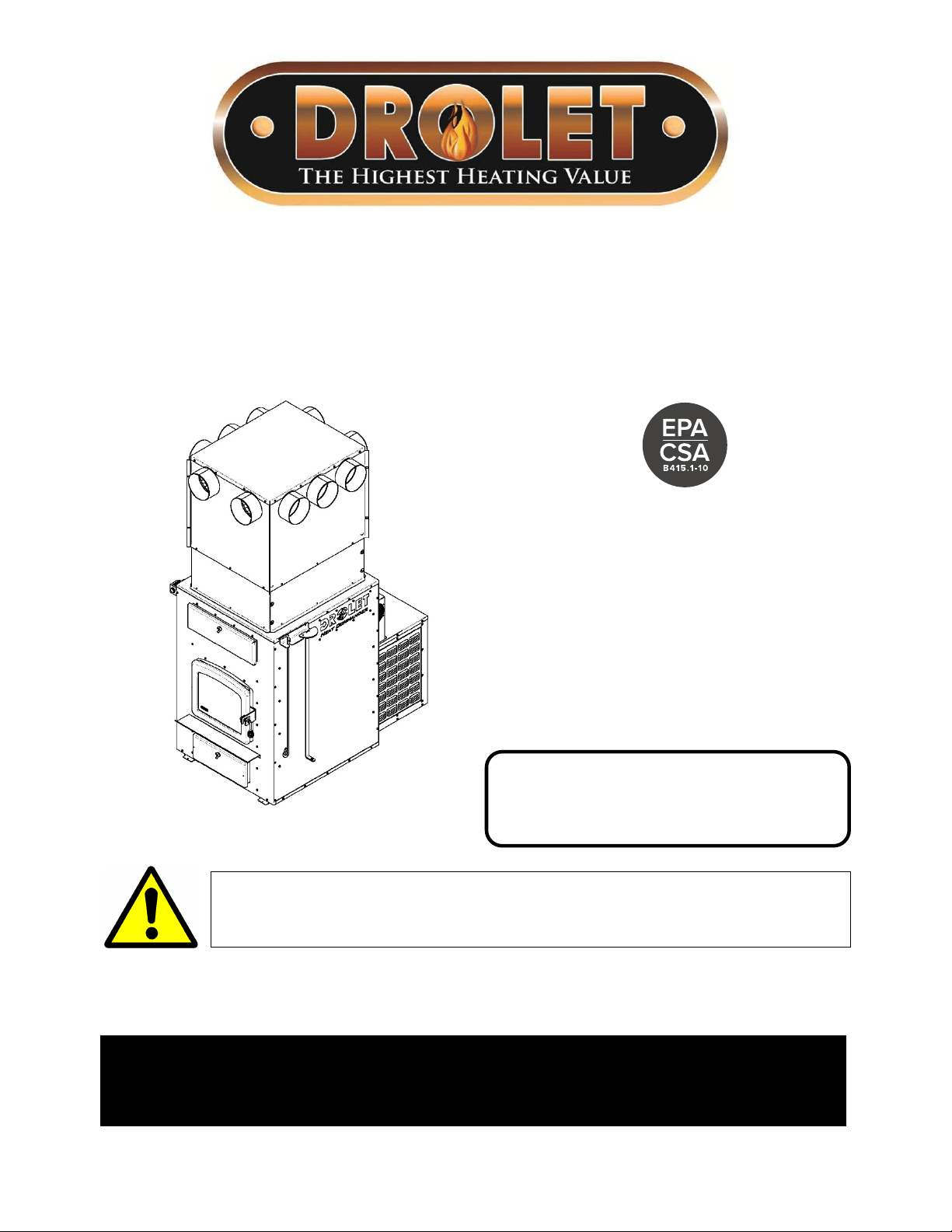
Installation and operating instructions for the
Heat Commander WOOD FURNACE
(DF02003 model)
Verified and tested for Canada
and the United States
by an accredited laboratory
Stove Builder International Inc.
250, rue de Copenhague,
St-Augustin-de-Desmaures (Quebec)
Canada G3A 2H3
After-sale service: 418-908-8002
E-mail: tech@sbi-international.com
Please keep this document!
This manual is available for free download on the manufacturer’s web site. It is a copyrighted
document. Re-sale is strictly prohibited. The manufacturer may update this manual from time
to time and cannot be responsible for problems, injuries, or damages arising out of the use
of information contained in any manual obtained from unauthorized sources.
READ THESE INSTRUCTIONS CAREFULLY BEFORE INSTALLING
AND OPERATING YOUR FURNACE.
WRITE THE SERIAL NUMBER HERE :


Heat Commander Furnace Installation and Operation Manual
3
THANK YOU FOR CHOOSING THIS DROLET WOOD FURNACE
As one of North America’s largest and most respected wood stove, furnace and fireplace
manufacturers, Stove Builder International takes pride in the quality and performance of all
its products. We want to help you get maximum satisfaction as you use this product.
In the pages that follow you will find general advice on wood heating, detailed instructions
for safe and effective installation, and guidance on how to get the best performance from
this furnace as you build and maintain fires and maintain your wood heating system.
Congratulations on making a wise purchase.
When this furnace is not properly installed, a house fire may result. To reduce the risk
of fire, follow the installation instructions. Contact local building or fire officials about
restrictions and installation inspection requirements in your area.
Please read this entire manual before you install and use your new furnace. Failure to
follow instructions may result in property damage, bodily injury, or even death. It is
important that you follow the installations guidelines exactly.
You may need to obtain a building permit for the installation of this furnace and the
chimney that it is connected to. Consult your municipal building department or fire
department before installation to determine the need to obtain one. We recommend
that you also inform your home insurance company to find out if the installation will
affect your policy.
REGISTER YOUR WARRANTY ONLINE
To receive full warranty coverage, you will need to show
evidence of the date you purchased your furnace. Keep your
sales invoice. We also recommend that you register your
warranty online at:
https://www.drolet.ca/en/warranty/warranty-registration
Registering your warranty online will help us to quickly track the
information we need about your furnace.

Table of contents
PART A – INSTALLATION ............................................................................. 6
INTRODUCTION ............................................................................................. 6
1 Regulations and safety warnings covering installation ....................... 7
1.1 Regulations covering furnace installation ..................................................................... 7
1.2 Cautions and warnings covering installation ................................................................ 7
1.3 Cautions and warnings covering installation of your pipe connector ........................... 8
2 Authorized and non-authorized configuration ...................................... 9
2.1 Authorized configurations in Canada and United States .............................................. 9
2.2 Authorized configurations in United States only ........................................................... 9
2.3 Not approved for installation in series with another furnace ...................................... 10
3 Setting up the unit and clearances ....................................................... 10
3.1 Unit location ............................................................................................................... 10
3.2 Certification label ........................................................................................................ 10
3.3 Clearances to combustible material ........................................................................... 11
4 The venting system ................................................................................ 15
4.1 The chimney ............................................................................................................... 15
4.2 The connector pipe .................................................................................................... 17
5 Hot air distribution and air return system ............................................ 20
5.1 Hot air distribution plenum height according to ceiling height .................................... 20
5.2 Assembling the hot air distribution plenum (A and B). ............................................... 22
5.3 Installation of the assembled plenum on the furnace ................................................. 26
5.4 Configuration and restrictions of hot air distribution system ....................................... 27
5.5 Air return system and filter ......................................................................................... 31
6 Air Supply in Conventional Houses ..................................................... 32
7 Electrical connection and calibration of the draw .............................. 34
7.1 Electrical connections ................................................................................................ 34
7.2 Furnace terminals identification ................................................................................. 36
7.3 Installation and connection of the “RTD” thermal probe ............................................. 36
7.4 Thermostat installation ............................................................................................... 37
7.5 Blower technical Data ................................................................................................ 40
7.6 Draft Calibration ......................................................................................................... 40
8 Tool Holder Installation ......................................................................... 42
Appendix 1: Optional air filters (AC01390, AC01391) ............................... 43

Heat Commander Furnace Installation and Operation Manual
5
Appendix 2: Optional air return adapter (AC01392) ................................. 44
PART B –OPERATION, MAINTENANCE AND TROUBLESHOOTING ...... 45
8.1 How to prepare or buy good firewood ........................................................................ 45
9 Operating your furnace .......................................................................... 48
9.1 How it works ............................................................................................................... 48
9.2 How Reload Button Works ......................................................................................... 49
9.3 How to light and reload the furnace ........................................................................... 50
9.4 Your first fires ............................................................................................................. 53
9.5 Lighting fires ............................................................................................................... 53
9.6 Maintaining wood fires ............................................................................................... 54
9.7 Additional fresh air supply .......................................................................................... 57
9.8 Ash drawer ................................................................................................................. 58
9.9 Prolonged power outage ............................................................................................ 58
10 Maintaining your wood heating system ............................................... 59
10.1 Furnace maintenance ................................................................................................ 59
10.2 Chimney maintenance ............................................................................................... 69
10.3 Firebricks inspection .................................................................................................. 70
10.4 Smoke pipe inspection ............................................................................................... 70
10.5 Blower motor maintenance ........................................................................................ 70
11 Troubleshooting ..................................................................................... 71
11.1 Installation of secondary air tubes and baffle ............................................................. 72
12 Exploded diagram and parts list ........................................................... 73
PART C – FEATURES AND SAFETY .......................................................... 83
13 General information ............................................................................... 83
13.1 Appliance performance
(1)
.......................................................................................... 83
13.2 General Features ....................................................................................................... 84
13.3 The benefits of low emissions and high efficiency ..................................................... 87
13.4 The SBI commitment to you and the environment ..................................................... 87
14 Safety information .................................................................................. 88
14.1 Cautions and warnings ............................................................................................... 88
14.2 Smoke detector .......................................................................................................... 89
DROLET LIMITED LIFETIME WARRANTY ................................................. 90

PART A – INSTALLATION
INTRODUCTION
This furnace uses the Dual Fire© technology with a two-stage electronic combustion
control. Find peace of mind with a self-regulated combustion that allows easy ignition. Its
automated air supply and self regulated systems synchronize with your thermostat to offer
additional safety, optimize comfort and reduce emissions with minimal maintenance.This
model meets the emissions limits of CSA B415.1-10 Standard and EPA 40CFR Part 60,
subpart QQQQ (2020 limit).
• We recommend that our woodburning hearth products be installed and serviced by
professionals who are certified in the United States by NFI (National Fireplace Institute
®
)
or in Canada by WETT (Wood Energy Technical Training) or in Quebec by APC
(Association des Professionnels du Chauffage).
BEFORE STARTING THE INSTALLATION, READ ALL THE INSTRUCTIONS BELOW
AND MAKE SURE YOU UNDERSTAND THEM. (IF IN DOUBT, CONTACT OUR
CUSTOMER SERVICE AT [email protected]). FAILURE TO COMPLY
WITH THESE INSTRUCTIONS MAY RESULT IN HAZARD TO YOUR SAFETY AND WILL
AUTOMATICALLY VOID THE WARRANTY.
Inspect the furnace to make sure that nothing has been damaged in the shipping. Pull out
the tools from the flue pipe and/or exchangers and firebox of the furnace.
IMPORTANT NOTE
FOR, INSTALLATION OF A CENTRAL HEATING VENTILATION SYSTEM, IT IS HIGHLY
RECOMMENDED TO CONSULT A HEATING SYSTEM VENTILATION SPECIALIST.
N.B.: STOVE BUILDER INTERNATIONAL INC. IS NOT RESPONSIBLE FOR POOR
APPLIANCE PERFORMANCES, DUE TO IMPROPER INSTALLATION OF EXHAUST
SYSTEM OR DUCTING.

Heat Commander Furnace Installation and Operation Manual
7
1 Regulations and safety warnings covering installation
1.1 Regulations covering furnace installation
CAUTION
FOLLOW LOCAL CODES (IF IN DOUBT, CONTACT YOUR LOCAL HEATING
APPLIANCE RETAILER, YOUR MUNICIPALITY OR YOUR FIRE DEPARTMENT.
Installation must be made in accordance with the following standards;
Canada: CSA-B365 - Installation code for solid-fuel-burning appliances and equipment.
CSA C22.1 - Canadian electrical code.
United-States: NFPA 90B - Standard for the installation of warm air heating and air-
conditioning systems. NFPA 70 - National Electrical Code.
1.2 Cautions and warnings covering installation
• THE INFORMATION GIVEN ON THE CERTIFICATION LABEL AFFIXED TO THE
APPLIANCE ALWAYS OVERRIDES THE INFORMATION PUBLISHED, IN ANY OTHER
MEDIA (OWNER’S MANUAL, CATALOGUES, FLYERS, MAGAZINES AND/OR WEB SITES).
• AIR DUCTS SERVING A GARAGE SHOULD NOT BE CONNECTED TO OTHER PARTS OF
A HOUSE AND THE DUCTING SERVING A HOUSE SHOULD NOT BE CONNECTED TO A
GARAGE.
• MIXING OF CHIMNEY COMPONENTS FROM DIFFERENT SOURCES OR MODIFYING
FURNACE COMPONENTS MAY RESULT IN HAZARDOUS CONDTIONS. WHERE ANY
SUCH CHANGES ARE PLANNED, STOVE BUILDER INTERNATIONAL INC. SHOULD BE
CONTACTED IN ADVANCE.
• ANY MODIFICATION OF THE APPLIANCE THAT HAS NOT BEEN APPROVED IN WRITING
BY THE TESTING AUTHORITY VIOLATES CSA B365 (CANADA), AND NFPA 90B (USA).
• CONNECT THIS FURNACE ONLY TO A LISTED UL 103 HT OR ULC S629 FACTORY-BUILT
CHIMNEY FOR USE WITH SOLID FUEL OR TO A LINED MASONRY CHIMNEY
CONFORMING TO NATIONAL AND LOCAL BUILDING CODES.
• IF REQUIRED, A SUPPLY OF COMBUSTION AIR SHALL BE PROVIDED TO THE ROOM OR
SPACE.
• DO NOT STORE NEAR WOOD FURNACE. RESPECT THE PRESCRIBED CLEARANCE
BETWEEN COMBUSTIBLES AND HEAT.
• DO NOT CONNECT THIS UNIT TO A CHIMNEY FLUE SERVING ANOTHER APPLIANCE.
• DO NOT INSTALL IN A MOBILE HOME.
• DO NOT INSTALL IN ALCOVE.
• IT IS FORBIDDEN TO USE PLASTIC REGISTER AT THE END OF THE OUTLET DUCT.
REGISTERS CAN BE VERY HOT IN THE EVENT OF A POWER FAILURE AND CAN SOFTEN
A PLASTIC REGISTER.

1.3 Cautions and warnings covering installation of your pipe connector
Please note that any high-efficiency wood heater like your Heat Commander can accumulate
gas and ignite suddenly, creating in rare occasions a burst that can put pressure on the
system when it is released. This burst could be powerful enough to detach the pipe
connector at the back of the unit if it is not properly secured, causing smoke to spill into the
room. For this reason, IT IS CRUCIAL THAT YOUR PIPE CONNECTOR BE PROPERLY
SECURED WITH AT LEAST 3 METAL SCREWS as indicated in the installation
section. Furthermore, to prevent this rare situation from occurring, it is always
recommended that you follow these simple loading rules:
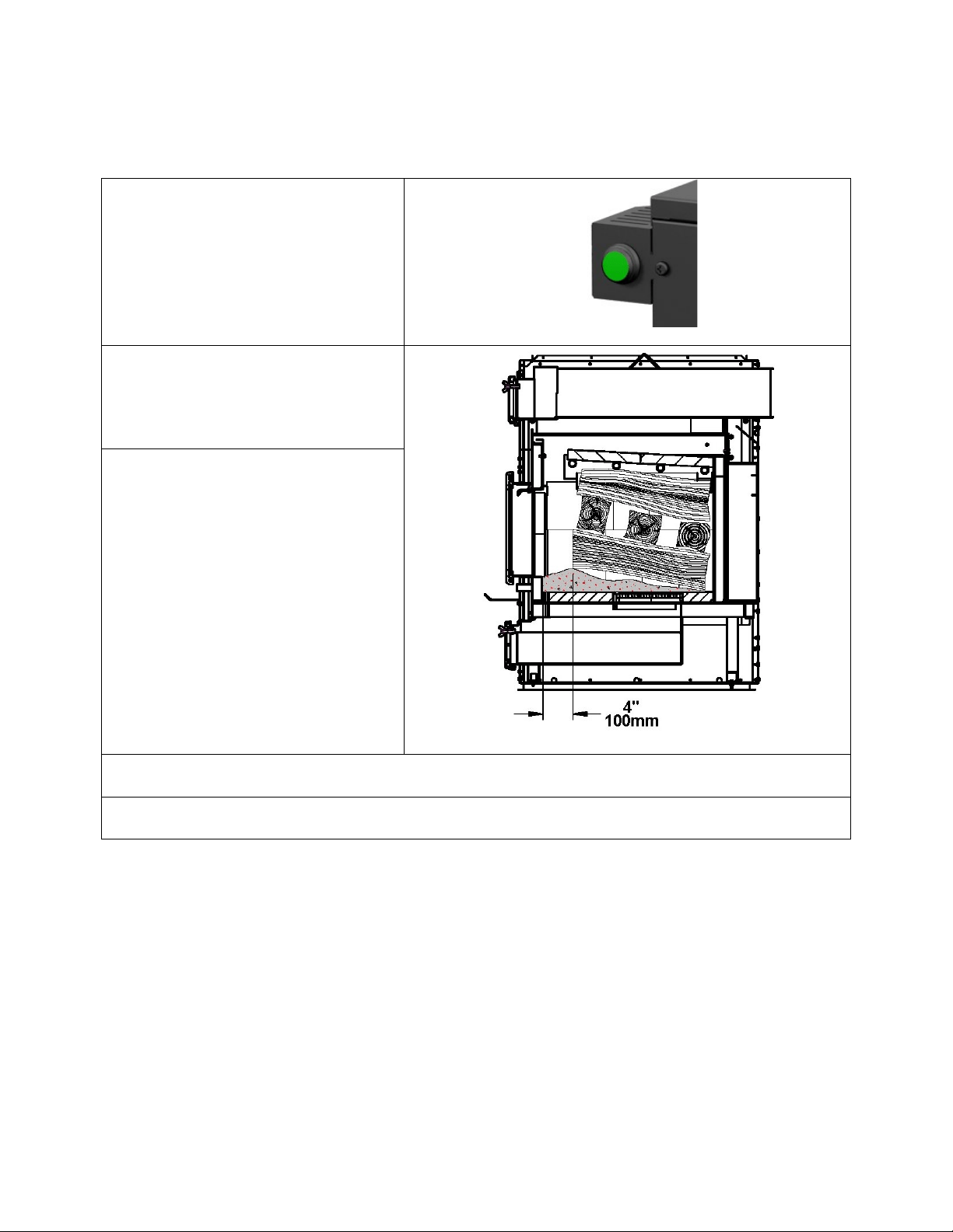
Hot ember bed (reload button light is ON or slowly blinking):
1. Make sure you do not have more than 4 inches (100 mm) of embers and ash
accumulation at the bottom of the firebox. If so, increase the target temperature on
the thermostat to burn the embers or remove ash when the unit has cooled down;
2. Empty your ash pan on a weekly basis to prevent the ash grate to plug;
3. Bring some hot embers to the front of the firebox before loading;
4. Load wood at the back of the firebox to leave approximately 4 to 5 inches (100 to 125
mm) of free space between the front of the firebox and the wood logs.
Cold ember bed (reload button light is turned OFF). This condition indicates the
furnace is cold and needs to be re-ignited:
1. Press the reload button;
2. Put crumbled sheets of paper and kindling on top of ash grate;
3. Put two logs in a North-South orientation, one on each side of the ash grate;
4. Crisscross additional logs on top of the first two logs;
5. Leave door ajar at a 45° angle from the closed position;
6. Wait for the paper and kindling ignition and close the door.
Heat Commander Furnace Installation and Operation Manual
9
2 Authorized and non-authorized configuration
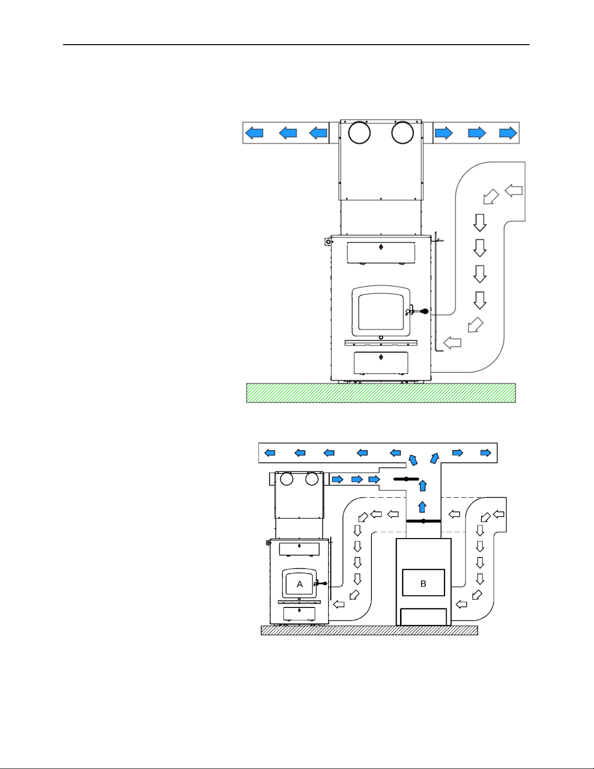
2.1 Authorized configurations in Canada and United States
The wood furnace is the only
appliance connected to the hot
air distribution duct system and
air return duct system.
2.2 Authorized configurations in United States only
Parallel add-on installation:
- (A) represents the wood
furnace.
- (B) represents the gas, oil or
electric existing furnace.
- Power input (B) should be
equal to or greater than (A).
- Each furnace must have its
own air return duct system.
- The highest clearances of
(A and B) and hot air
distribution and air return
ducts of must be respected.
- Static pressure of (A) must
be adjusted to 0.20 in. W.C.
(50 Pa).
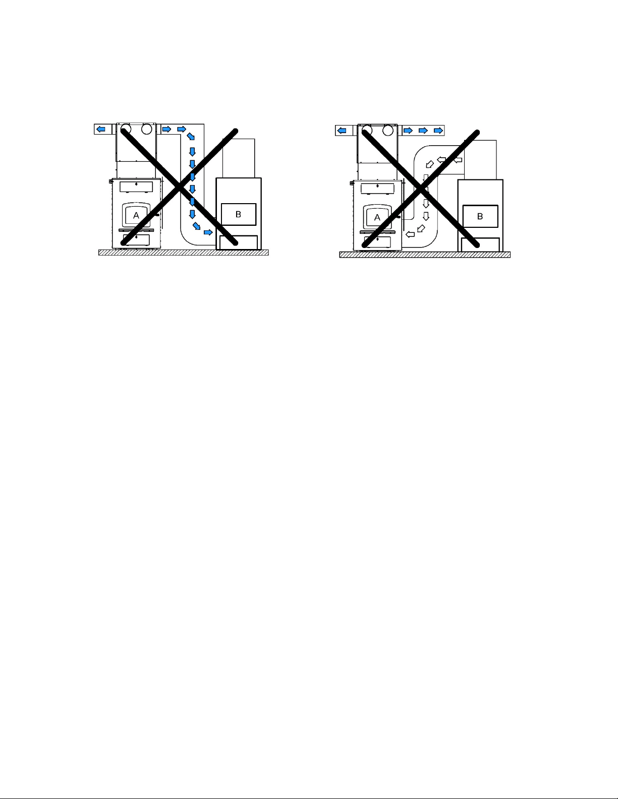
2.3 Not approved for installation in series with another furnace
- The hot air duct (A) must not be
installed in the air return of (B).
- The hot air duct (B) must not be
installed in the air return of (A).
3 Setting up the unit and clearances
To reduce the risk of vibration, the furnace must be leveled in both directions and supported
evenly to ensure stability.
3.1 Unit location
The furnace must be installed in a location:
- Where outside air supply will be sufficient for proper combustion, otherwise install
the optional fresh air supply;
- Where connector is as short as possible in order to minimize the use of 90
o
elbows
and horizontal lengths;
- That ensure a proper installation and safe operation of the appliance;
- Where the owner can ensure cleanliness of the room in the event of negative
pressure or temporarily negative;
- Where room to perform maintenance is sufficient and safe.
3.2 Certification label
N.B.: THIS APPLIANCE MUST BE INSTALLED IN ACCORDANCE WITH THE
INSTRUCTIONS ON THE CERTIFICATION LABEL APPLIED ON THE UNIT.
Location: You will find the certification label on the back of the appliance.
Information found on the certification label always overrides the information published in any
other publication.
Content of certification label: Model number, serial number, certification agency,
Standards, clearances to combustible material, as well as the main safety cautions.
Heat Commander Furnace Installation and Operation Manual
11
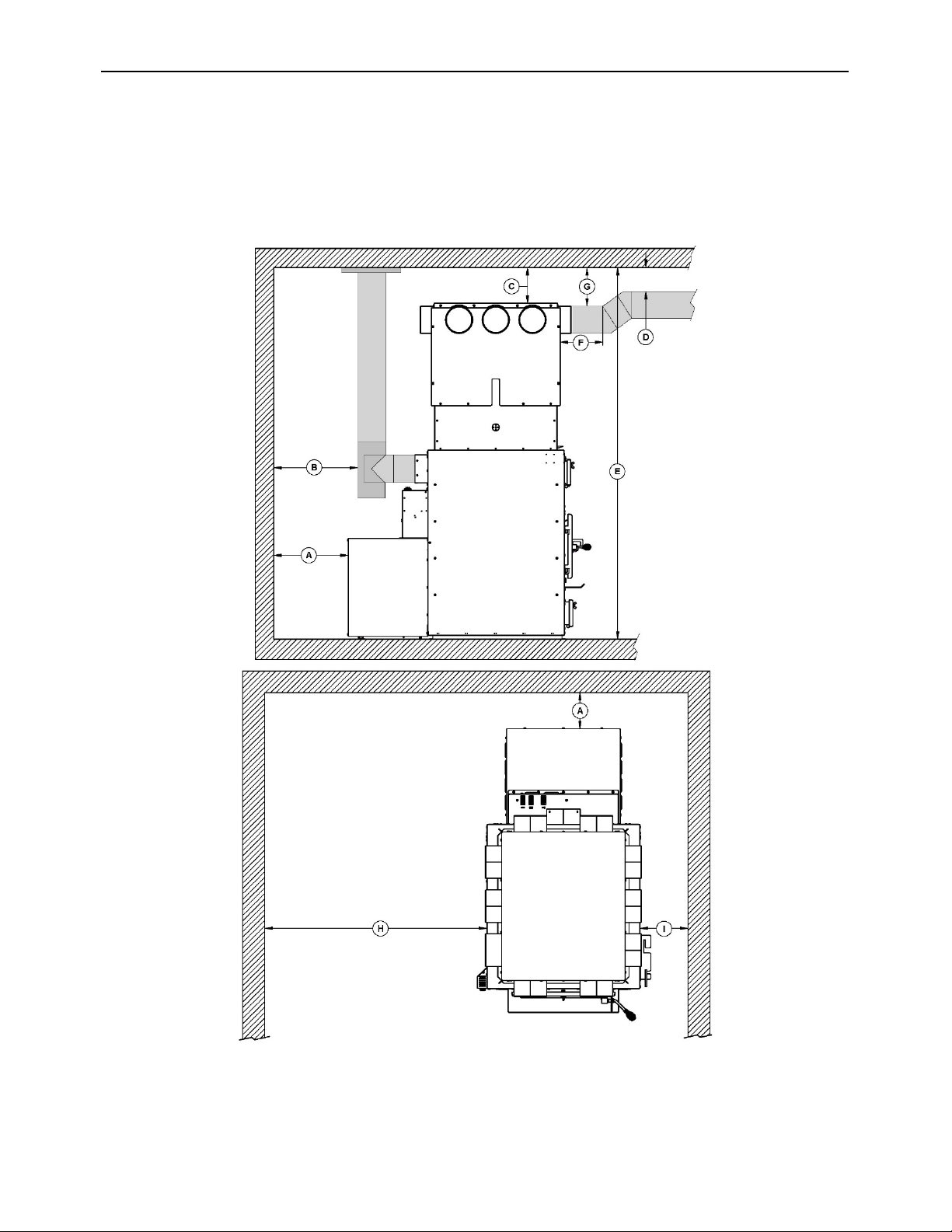
3.3 Clearances to combustible material
The clearances shown in this section have been determined by safety tests under normal
and even abnormal operating conditions according to procedures set out in standards CSA
B366.1 (Canada) and UL 391 (U.S.A.). Respecting the minimum clearances is mandatory
to prevent risk of fire.
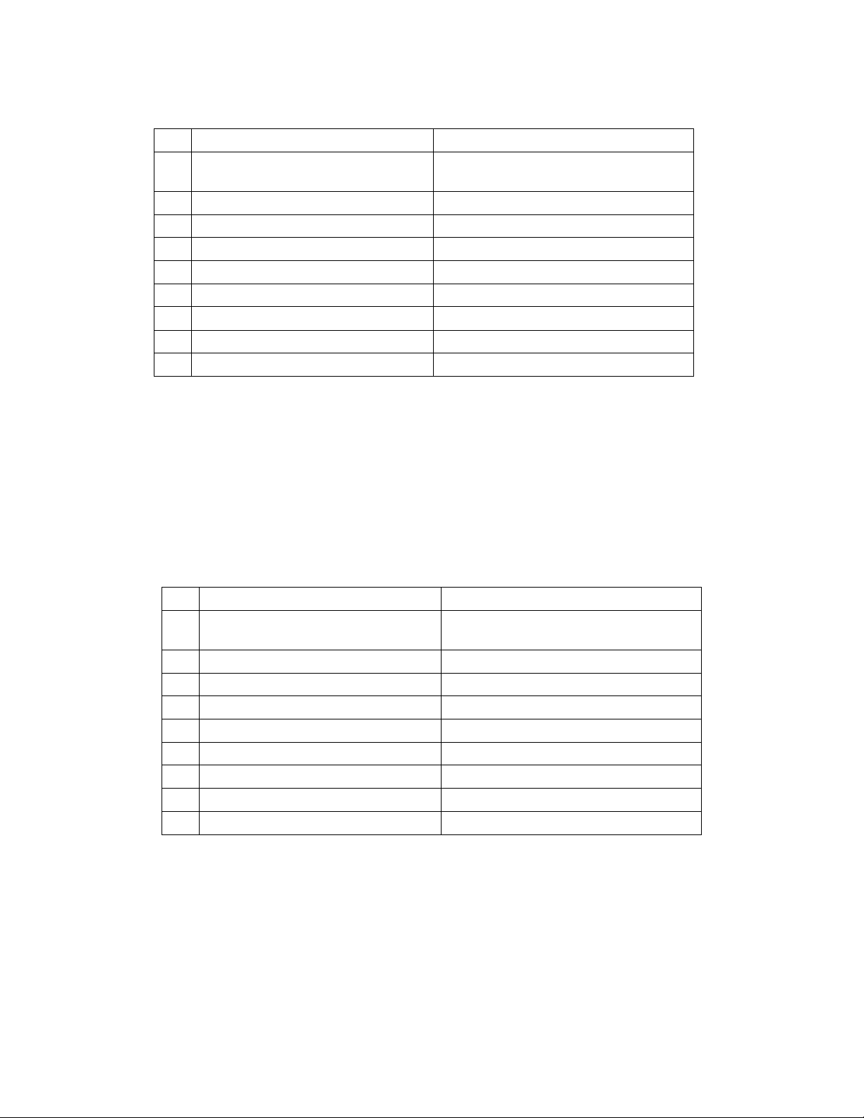
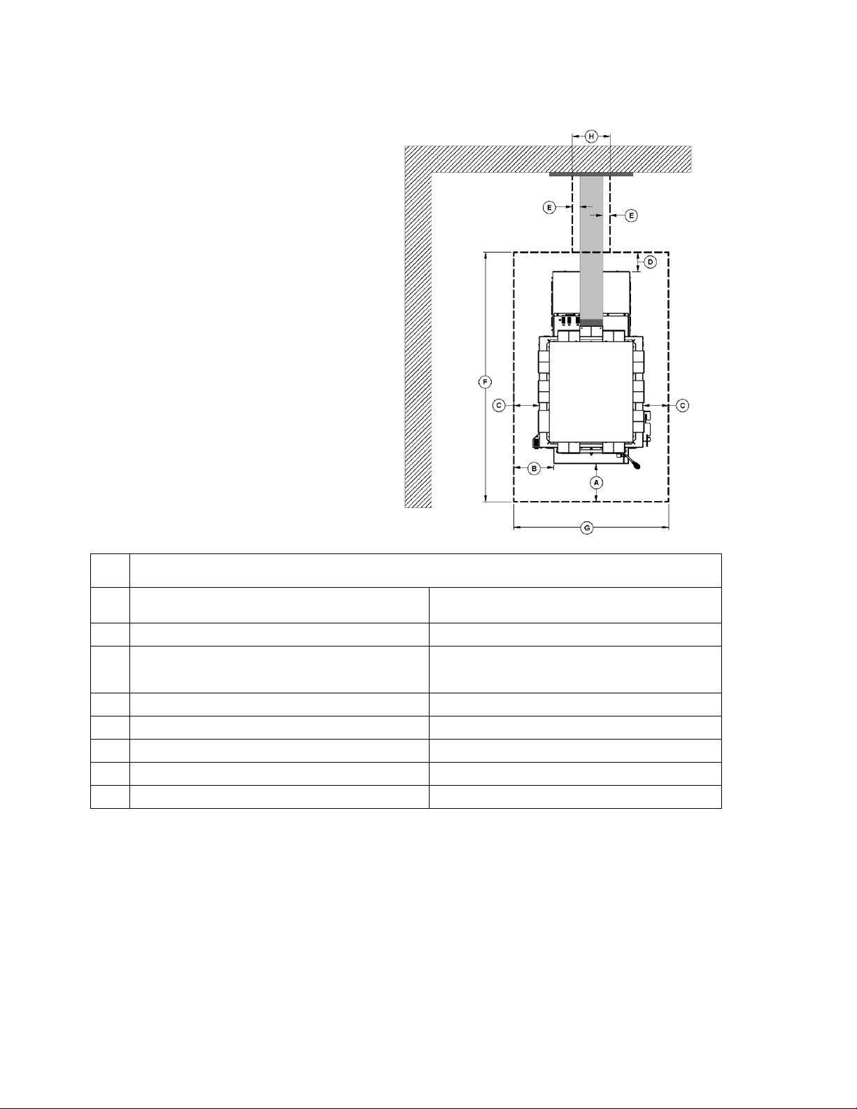
3.3.1 Clearances with single wall pipe
CANADA
É.-U.
A
14.25" (362 mm) (from the
back of the blower box)
14.25" (362 mm) (from the back
of the blower box)
B
18" (457 mm)
18" (457 mm)
C
5" (127 mm)
5" (127 mm)
D
1" (25 mm)
1" (25 mm)
E
69" (175 cm) minimum
69" (175 cm) minimum
F
12’’ (305 mm)
12’’ (305 mm)
G
1’’ (25 mm)
1’’ (25 mm)
H¹
24" (610 mm) minimum
24" (610 mm) minimum
I
11" (279 mm)
11" (279 mm)
¹A minimum clearance to the left is required for maintenance or replacement of
components, however, a larger clearance is suggested.
3.3.2 Clearances with double wall connector
(The use of a single wall pipe assembly with a heat shield certified to
6 "combustible materials, can be used. Only in this case, the same
clearances apply as with a certified double pipe.)
CANADA
É.-U.
A
6.75" (171 mm) (from the
back of the blower box)
6.75" (171 mm) (from the back
of the blower box)
B¹
11.5" (292 mm)
11.5" (292 mm)
C
5" (127 mm)
5" (127 mm)
D
1" (25 mm)
1" (25 mm)
E
69" (175 cm) minimum
69" (175 cm) minimum
F
12’’ (305 mm)
12’’ (305 mm)
G
1’’ (25 mm)
1’’ (25 mm)
H²
24" (610 mm) minimum
24" (610 mm) minimum
I
11" (279 mm)
11" (279 mm)
¹Recommended clearance, otherwise use the clearance provided by the double wall
black pipe manufacturer.
²A minimum clearance to the left is required for maintenance or replacement of
components, however, a larger clearance is suggested.
Heat Commander Furnace Installation and Operation Manual
13
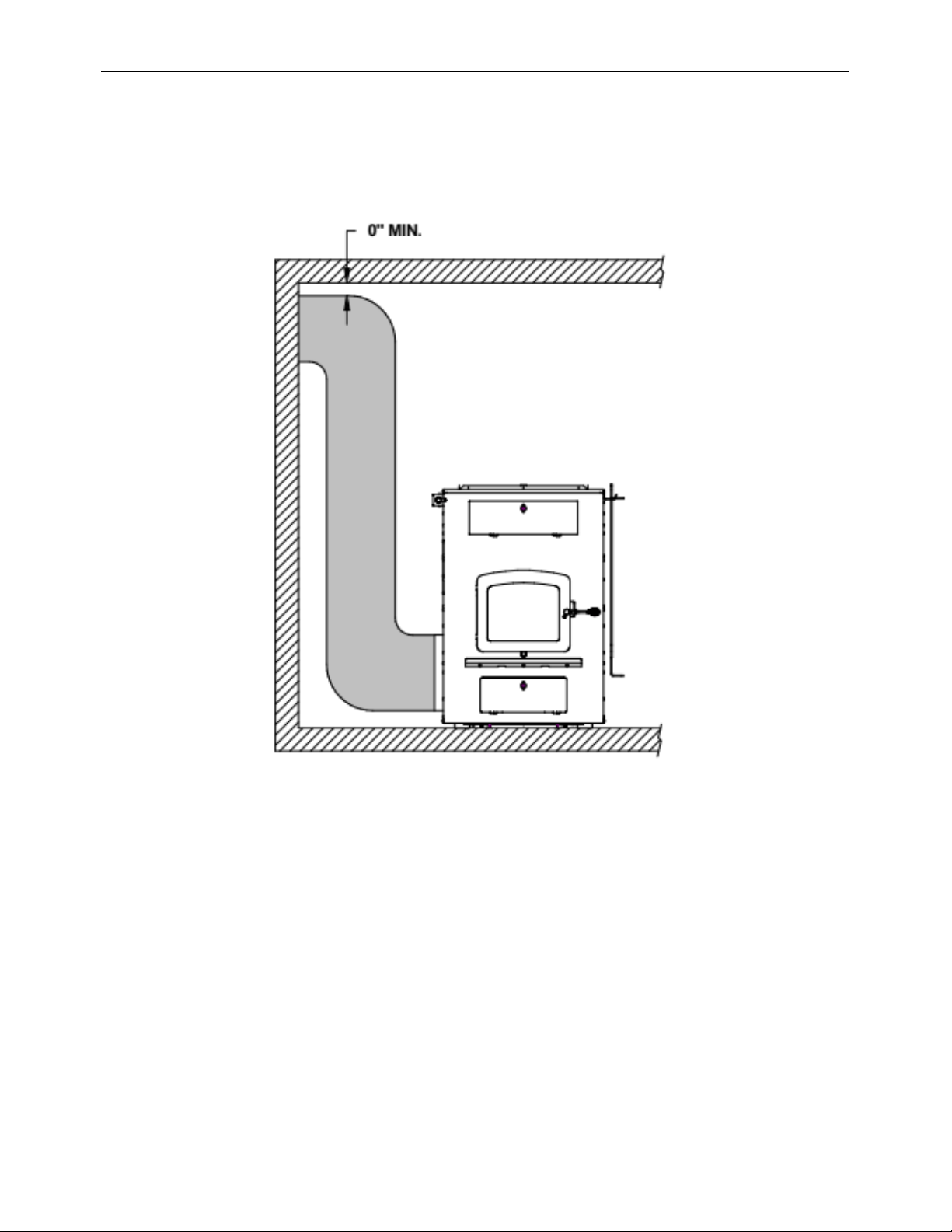
3.3.3 Cold air return ductwork clearances
The cold air return system can be connected to a new or to an existing cold air return
ductwork. In both cases, the minimum clearance to combustible material is 0" (0 mm).
3.3.4 Floor protection
- If the floor is made of non-
combustible material, no floor
protector is required.
- If the floor is made of combustible
material, a floor protector is required
(see table below).
FLOOR PROTECTION*
CANADA
USA
A
18" (457 mm) From door opening
16" (406 mm) From door opening
B
N/A (USA only)
8" (203 mm)
From door opening
C
8" (203 mm)
N/A (Canada only)
D
8" (203 mm) – Note 1
N/A (Canada only)
E
N/A (USA only)
2” (51 MM) - Note 2
F
43 ¾’’ (1111 mm)
30 ¼’’ (769 mm)
G
74’’ (1880 mm)
64’’ (1626 mm)
*Steel with a minimum thickness of 0.015" (0.38 mm) or ceramic tiles sealed together with
grout. No protection is required if the unit is installed on a non-combustible floor (ex:
concrete).
Note 1: The floor protection at the back of the furnace is limited to the furnace’s required
clearance (see (A) 3.3 Clearances to combustible material) if such clearance is smaller than
8" (203 mm).
Note 2: Only required under the horizontal section of the connector. Must exceed each side
of the connector pipe by at least 2" (51 mm).
Heat Commander Furnace Installation and Operation Manual
15
4 The venting system
WARNING:
DO NOT INSTALL A MANUAL DAMPER ON THIS FURNACE.
CAUTION: BEFORE THE CONNECTOR PIPES ARE INSTALLED, MAKE SURE THAT
THE EXHAUST PIPE AND / OR THE EXCHANGERS OF THE FURNACE ARE FREE OF
ALL ITEMS.
4.1 The chimney
- The furnace must be connected to a factory-built metal chimney that complies with UL
103 HT (USA) or ULC S629 (Canada).
o Strongly recommended inner diameter: 6" (152 mm).
o A chimney having a diameter of 7" (178 mm) is permitted, if it allows the proper
venting of combustion gases and that such application is verified and authorized
by a qualified installer. Otherwise, the diameter of the flue must be reduced to 6"
(152 mm) by the use of a stainless steel liner made for this purpose.
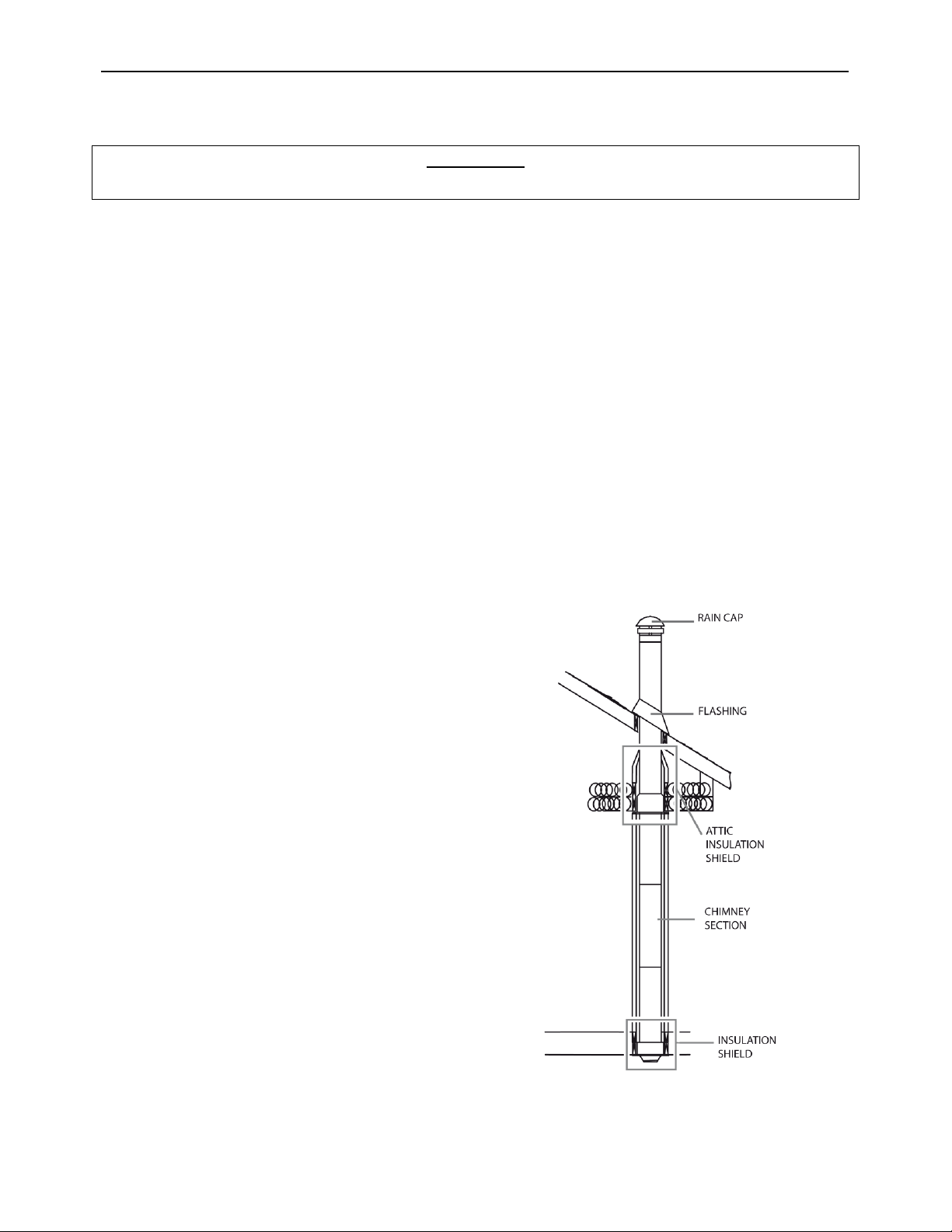
4.1.1 Factory-built metal chimneys
To be suitable, a factory-built metal chimney also called “high temp” chimney, must comply
with UL 103 HT (U.S.A.) or ULC S629 (Canada).
- Use only components intended for the
brand and model of chimney you are
using.
- Never substitute parts from other
chimney brands.
- Never fabricate your own components.
- The chimney must be a type suitable for
solid fuel.
- To be safe and effective, the chimney
must be installed exactly in accordance
with the manufacturer’s instructions.
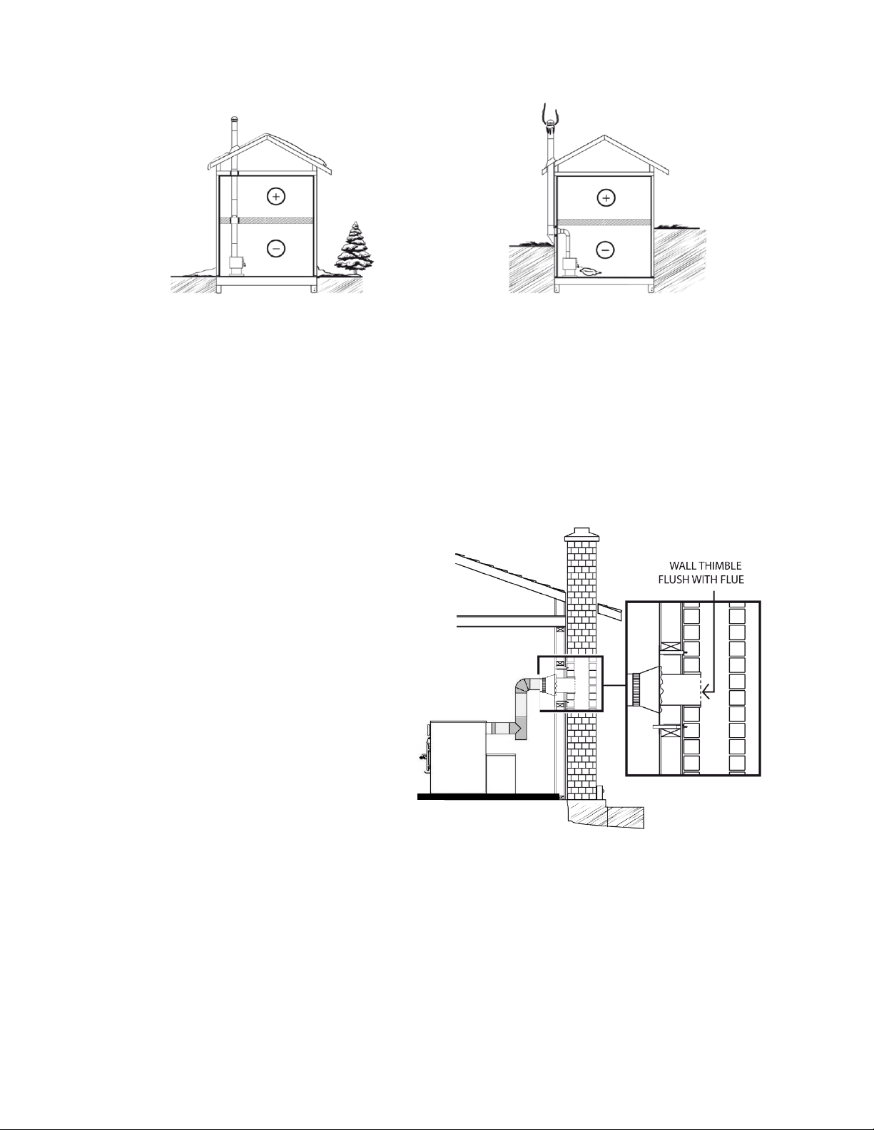
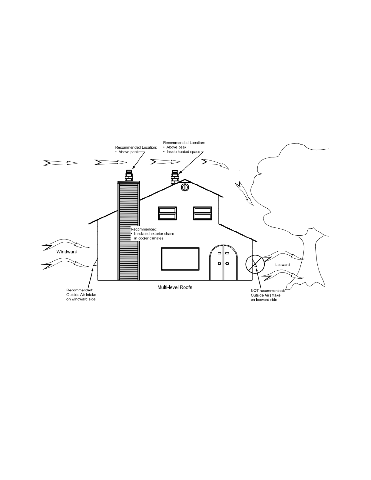
Good system design
Inside chimneys are preferred because
even when no fire is burning, there is
normally upward flow in the system.
Inferior system design
Outside chimney may be a problem if there
are long periods of inactivity or low fire
temperatures. A cold chimney may down
draft making start up difficult.
4.1.2 Masonry chimneys
The furnace may also be connected to a masonry chimney, provided the chimney complies
with the construction rules found in the building code enforced locally.
- The chimney must have a clay
liner.
- If the masonry chimney has a
square or rectangular liner that is
larger in cross sectional area than
a round 6" (152 mm) flue, it should
be relined with a suitably listed 6"
(152 mm) stainless steel liner.
- When passing through a
combustible wall, the use of an
insulated listed thimble is required.
- If a stainless steel liner is installed,
it is recommended to extend the
liner 12" (305 mm) to 18" (457 mm)
above the top of the masonry
chimney to favor the draw.
Heat Commander Furnace Installation and Operation Manual
17
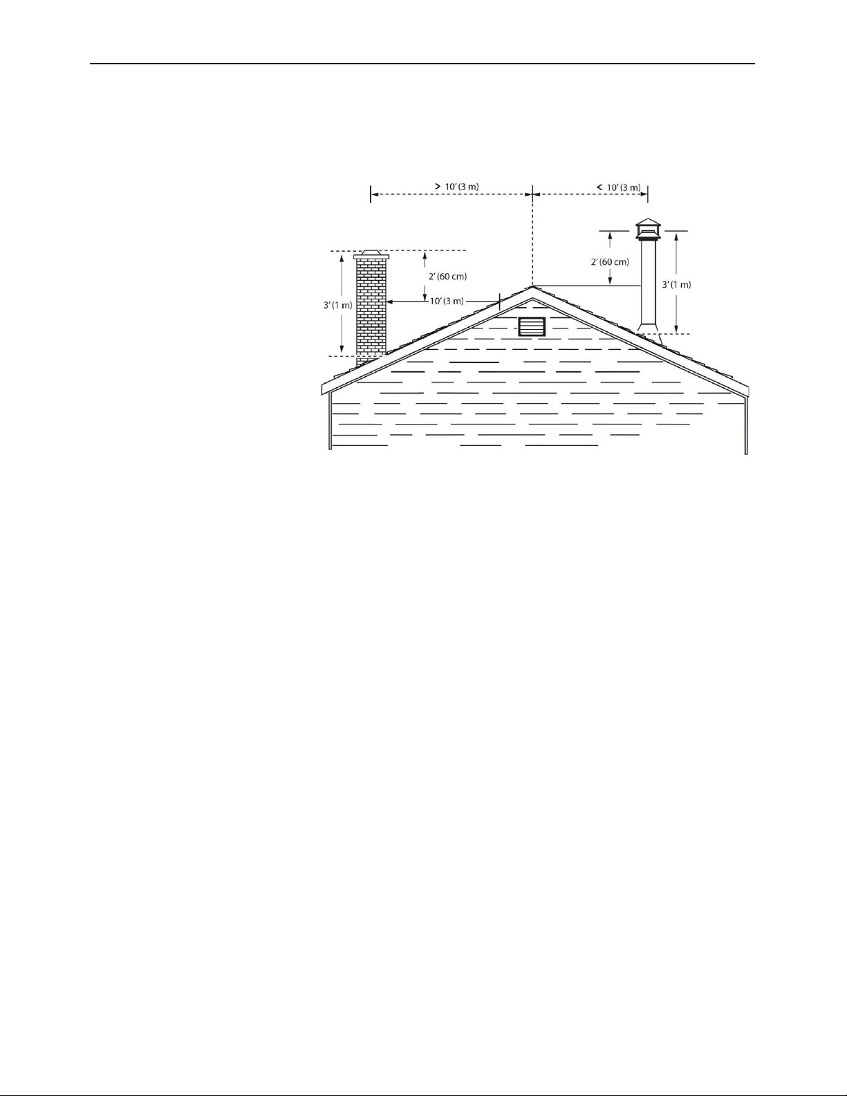
4.1.3 Minimum chimney height
The top of the chimney should be tall enough to be above the air turbulence caused when
wind blows against the house and its roof.
- The chimney must
extend at least 3 ft. (1 m)
above the highest point
of contact with the roof.
- Extend at least 2 ft.
(61 cm) higher than any
roof line or obstacle
within a horizontal
distance of 10 ft. (3 m).
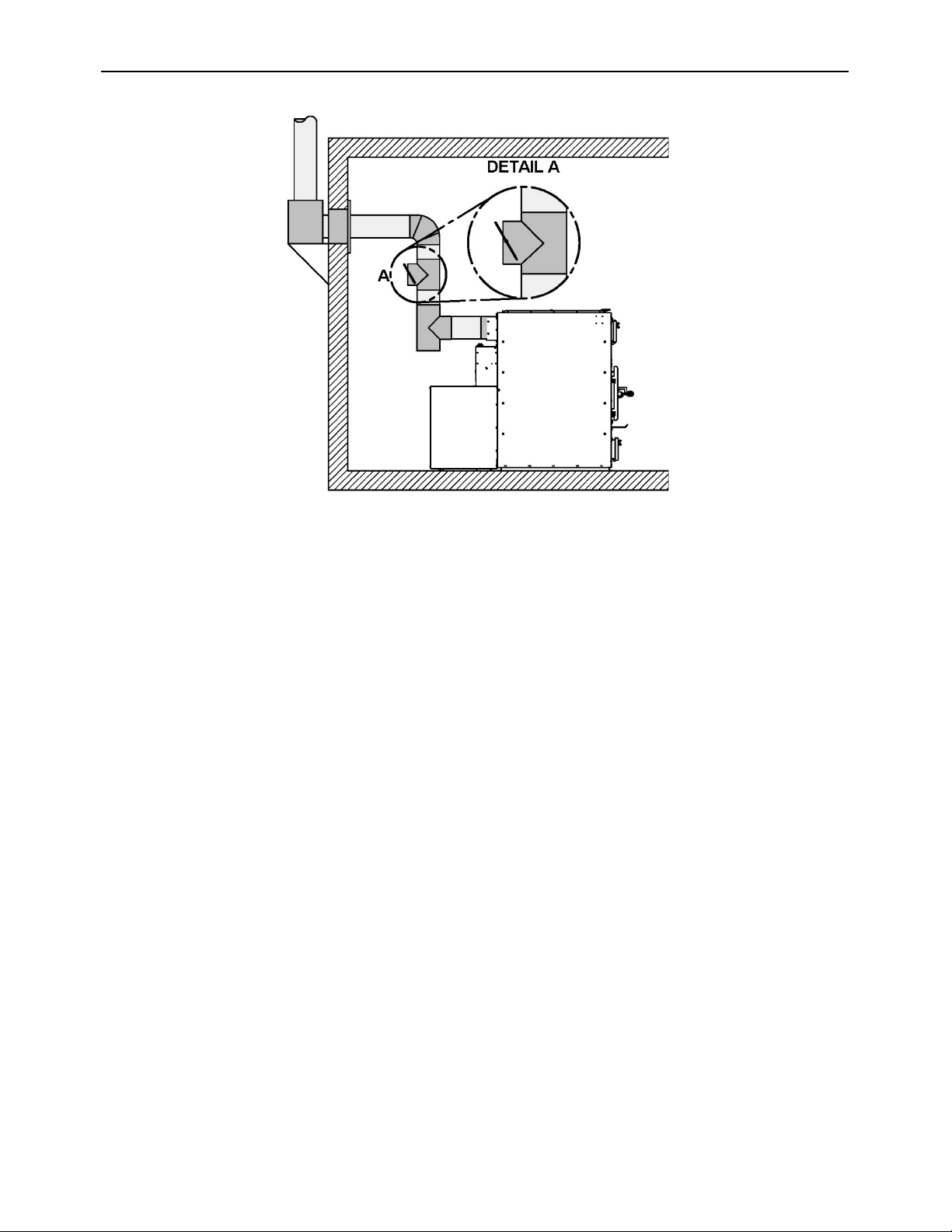
4.2 The connector pipe
o Recommended inner diameter: 6" (152 mm)
• If an increaser must be used (max 6" (152 mm) to 7" (178 mm)), it must be
installed as close as possible to the chimney.
4.2.1 Best practices and requirements of the installation code
o Where passage through a wall or partition of combustible construction is desired,
the installation shall conform to CAN/CSA-B365, Installation Code for Solid-Fuel-
Burning Appliances and Equipment;
o A flue pipe must never pass through a combustible floor or ceiling or through an
attic, roof space, closet or concealed space;
o Minimum upward slope towards the chimney: 1/4 in/ft. (20 mm/m);
o The maximum horizontal run is 10’ (3 m). Do not count the starting elbow;
o All flue pipe joints must be secured with three screws. Failure to secure them to
each other may allow for separation and leaks;
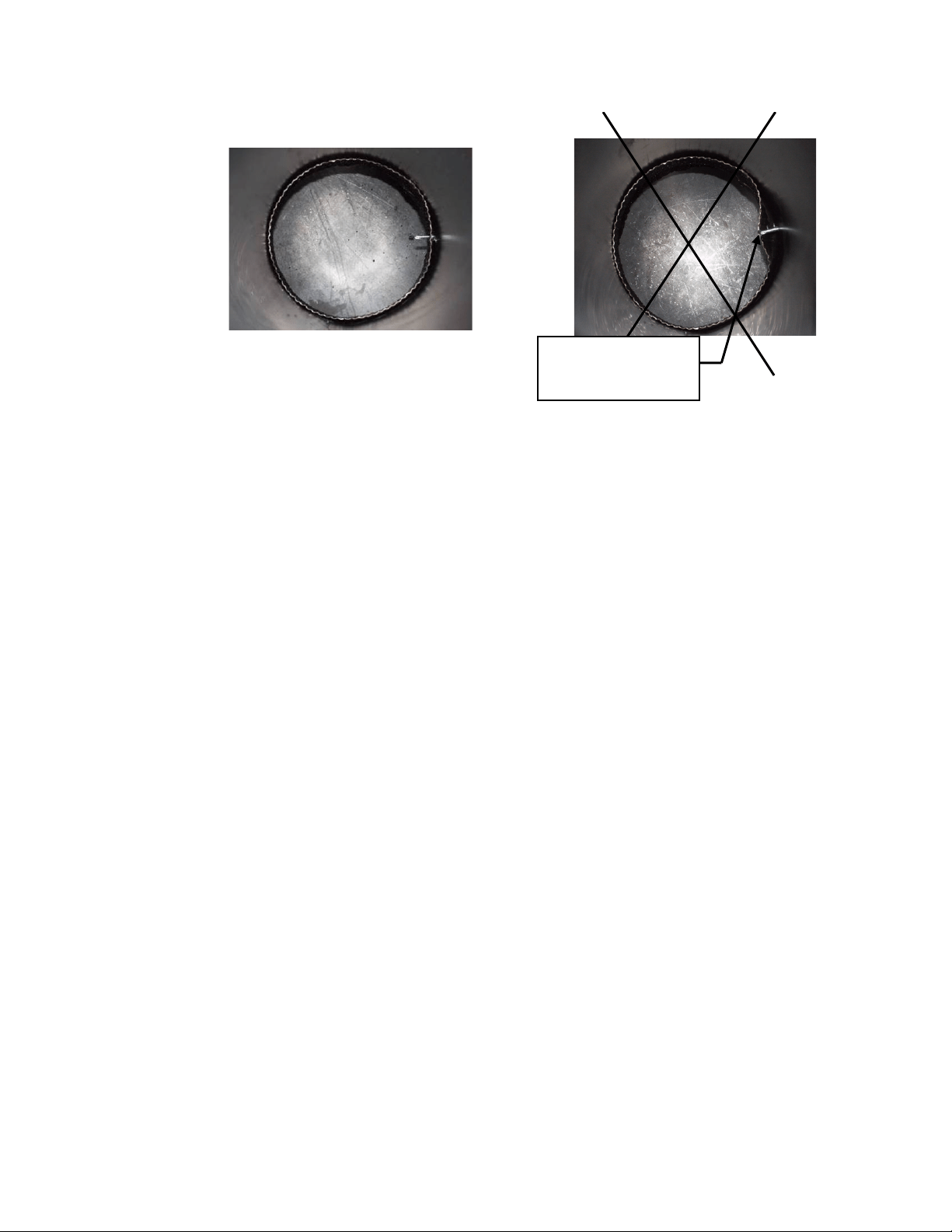
Proper installation
improper installation
o Maximum unsupported horizontal length: 3 feet (1 m);
o Galvanized flue pipes must not be used because the coatings vaporize at high
temperatures and release dangerous gases;
o Flue pipes must be at least 24 gauge in thickness;
o The chimney connector must be in good condition;
o Flue pipe joints should overlap 1 1/4". (30 mm);
o Straight up installations need to have either a connector where one end has no
fastener or a telescopic/adjustable length;
o Removal of the assembly for cleaning should not require that the furnace be
moved;
o The male ends of the sections must be oriented towards the appliance so that
falling dust and condensation stay inside the pipe;
o A straight flue pipe assembly offers the least restriction to gas flow and results in
stronger draft. Straight assemblies also need less maintenance as there are is
less restrictions from corners to collect creosote;
o The use of 45° elbows is strongly recommended;
o Elbow added resistance is equivalent to : a 90° elbow = 5’ (152 cm), a 45° elbow
= 2.5’ (76 cm);
o Never use more than two 90° elbows.
CAUSES
RESTRICTION
Heat Commander Furnace Installation and Operation Manual
19
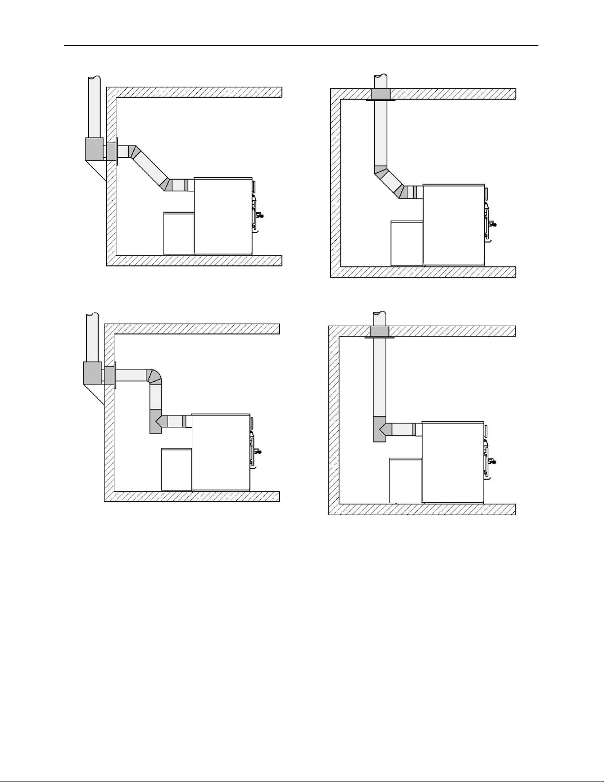
Use 45° elbows where possible, rather than 90° elbows.
Alternative installations with 90° elbow or tee.
5 Hot air distribution and air return system
The Drolet furnace is designed and equipped with a hot air distribution plenum that may
receive 6 to 10, 6" (152 mm) diameter round ducts.
The installer is responsible of the performance of the distribution ducts and the air
return system. It will have a direct effect on the ability of the blower to distribute heat
efficiently throughout the house. The number, size and length of the ducts of the
distribution system and return air will vary depending on the configuration and
characteristics of each house.
N.B.: The furnace air jacket is not totally airtight. It is normal to detect some air leaks
at the jacket’s joints.
Components provided with the furnace to assemble the hot air distribution plenum:
10 start-off
adapter (A)
4 block-off cap
(B)
44 Type A
#10 black
screws
(C)
25 #8 selt-
taping black
screws (D)
4 corners
reinforcem
ent (E)
1 reload
button
sticker
reminder (F)
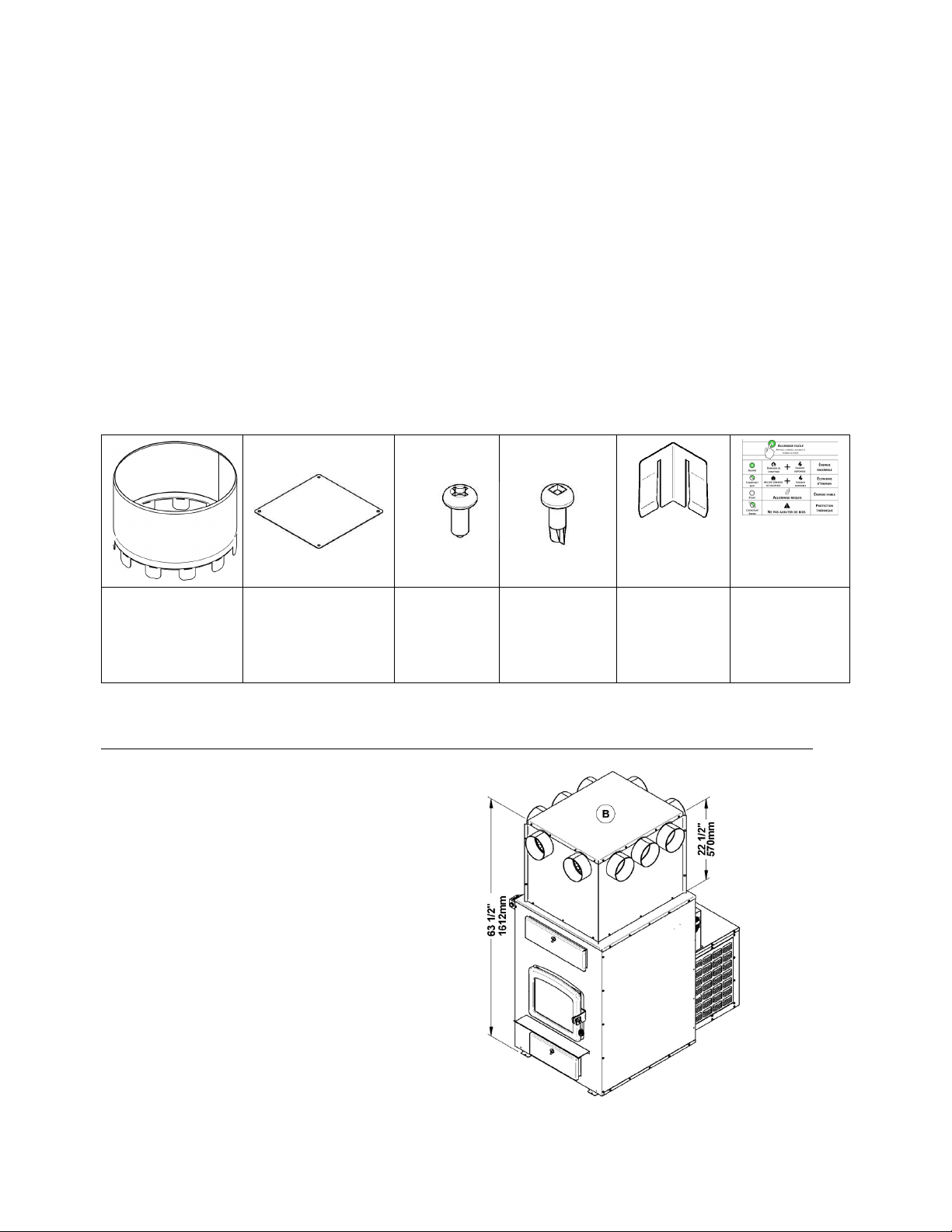
5.1 Hot air distribution plenum height according to ceiling height
Remember to take into account the 5" (127 mm) clearance to combustibles above the plenum.
5.1.1 Plenum’s minimum height (63 ½’’
(1613mm) from the furnace base)
For a minimum ceiling height of 69" (1750
mm).
Heat Commander Furnace Installation and Operation Manual
21
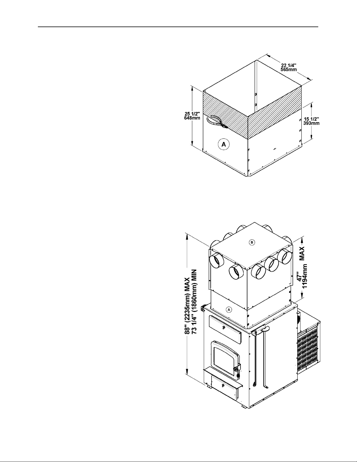
5.1.2 Adjustable height of the plenum
When the ceiling height, measured from the
floor, is lower than 78 1/4’’ (1990 mm), it will
be possible to cut the plenum extension (A)
of at most 10" (254 mm). The plenum
extension (A) must therefore have a
minimum height of 15 1/2'' (393 mm).
Warning: The plenum extension (A) should
not obstruct the openings for the hot air
distribution of the plenum (B). The shaded
area represents the maximum cutting of
plenum extension (A).
5.1.3 Adjustable height of the plenum
(A and B); without cutting 73 1/4"
to 88" (1860 to 2240 mm).
For ceiling height from 78 1/4" (1990 mm) to
93’’ (2362mm) and more.
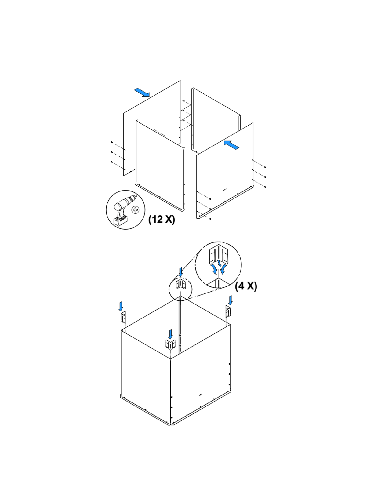
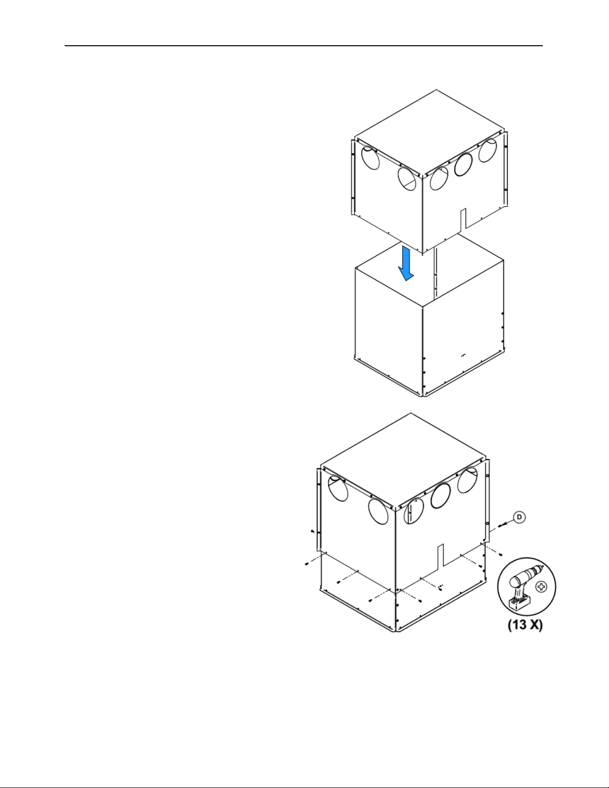
5.2 Assembling the hot air distribution plenum (A and B).
5.2.1 Assembling the plenum extension (A) by means of 12 screws (C) and corner
reinforcements (E)
Heat Commander Furnace Installation and Operation Manual
23
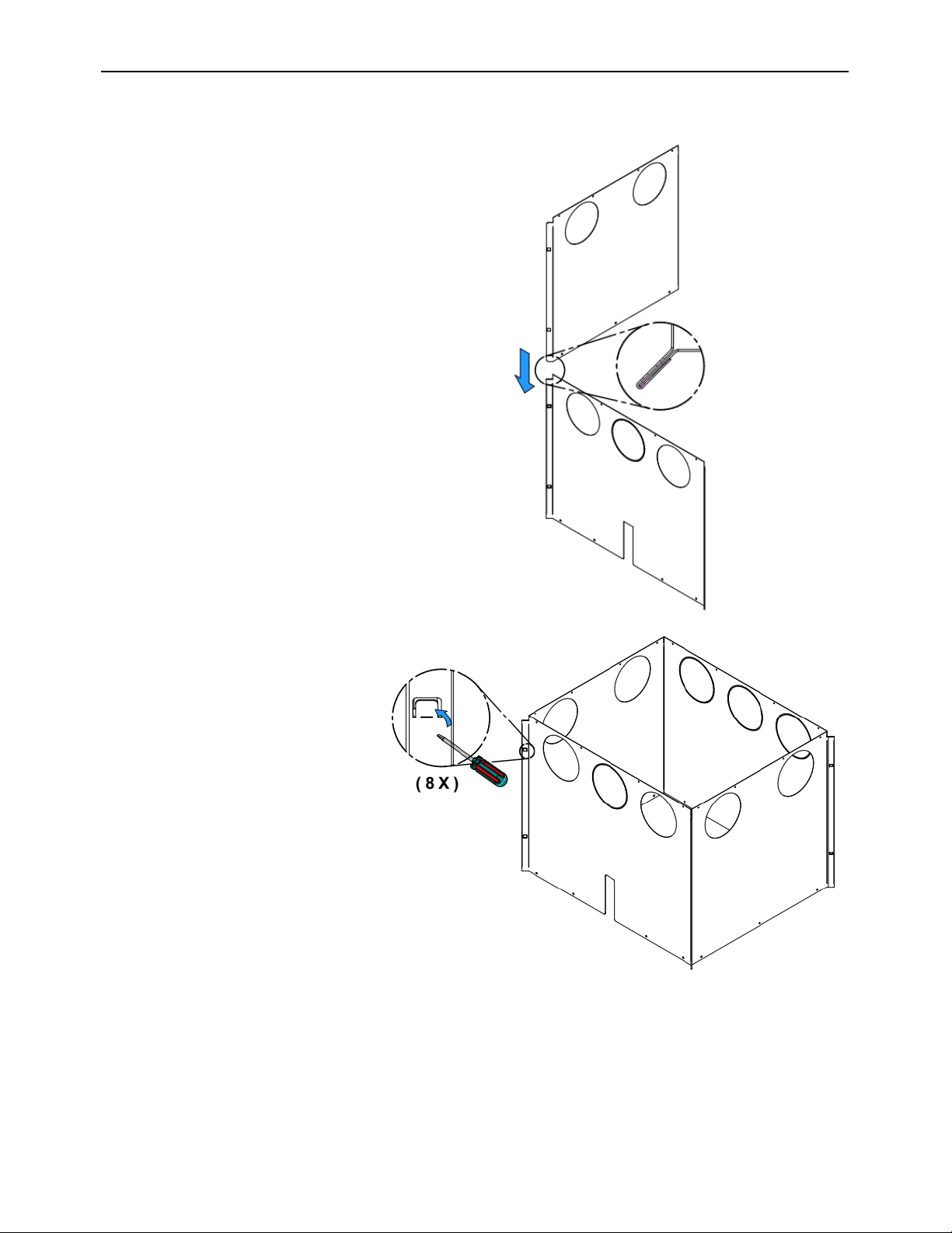
5.2.2 Assembling the plenum (B)
Insert the male end of each
panel in the female part of
the adjacent panel.
Secure the assembly by
bending the two metal tabs in
the center of each corner.
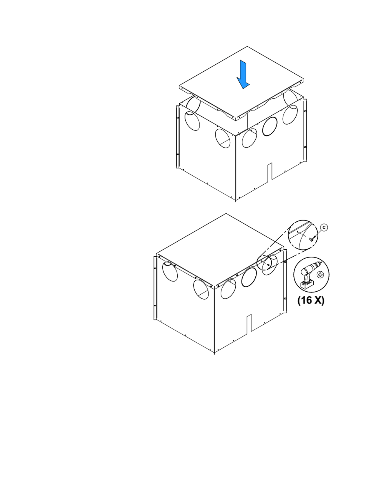
Install the cover on the part
(B) of the assembly and
secure it with 16 screws (C).
Heat Commander Furnace Installation and Operation Manual
25
5.2.3 Assembling the plenum extension (A) to the plenum (B)
Slide plenum (B) over the plenum
extension (A) to the extent determined
in Section 5.1.
Using 13 self-drilling screws (D),
secure the plenum (B) to the plenum
extension (A).
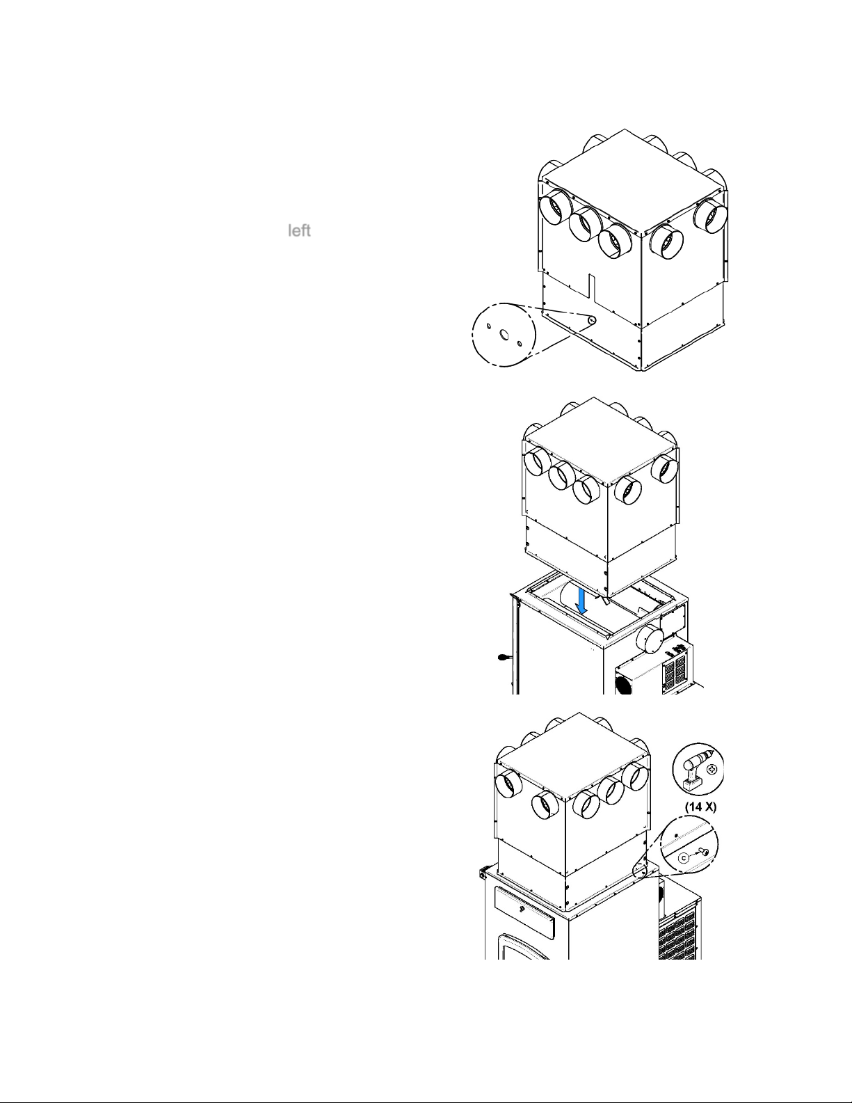
5.3 Installation of the assembled plenum on the furnace
Identify the left side of the plenum, it is
provided with holes for the installation of the
“RTD” thermal probe.
Also, 5 holes are aligned with the fold of the
top of the furnace on the
left
side and three
holes on the other sides. This allows you to
secure the plenum properly.
Install the assembly on the furnace, taking
care to insert the 4 folds on top of the furnace
inside the plenum.
Using 14 screws (C), secure the plenum to
the furnace.
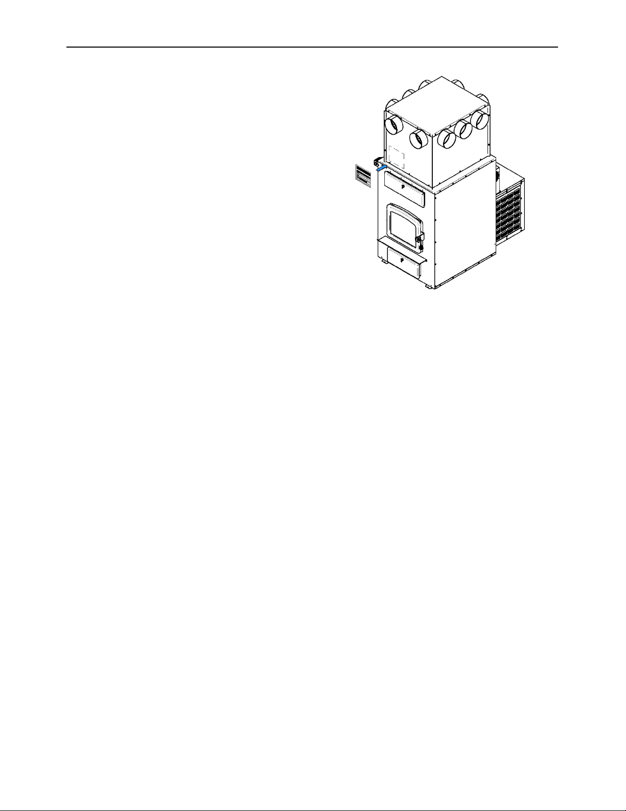
Heat Commander Furnace Installation and Operation Manual
27
Apply the reload button operation reminder
sticker (G) on the front of the plenum. The
sticker is provided with the owner’s manual
kit.
5.4 Configuration and restrictions of hot air distribution system
5.4.1 Start-off plenum
- The plenum can be adjusted from 63 1/2" (1610 mm) to 88" (2240 mm) depending on
ceiling height. See Section 5.1: Hot air distribution plenum height according to
ceiling height.
- The plenum has a minimum height of 22 1/2" (571 mm) and a maximum height of 47’’
(1194mm) from the top of the furnace (X).
- The minimum clearance (C) between the top of the plenum and the ceiling is
5" (127 mm).
- The ducts minimum clearance (D) to combustible materials is 0" (0 mm).
- The minimum clearance (G) of the ducts to combustible materials is 1" (0 mm) along the
length (F) 12" (305mm).
- The ducts may pass through a combustible wall maintaining a clearance of 0" (0 mm)
around ducts.
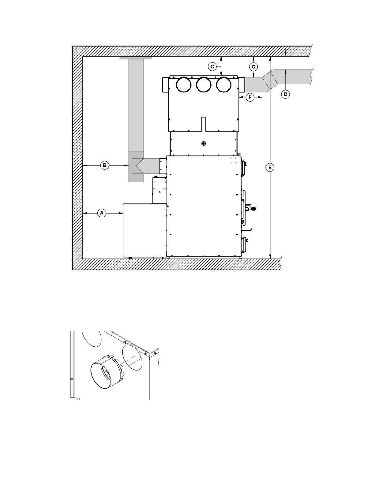
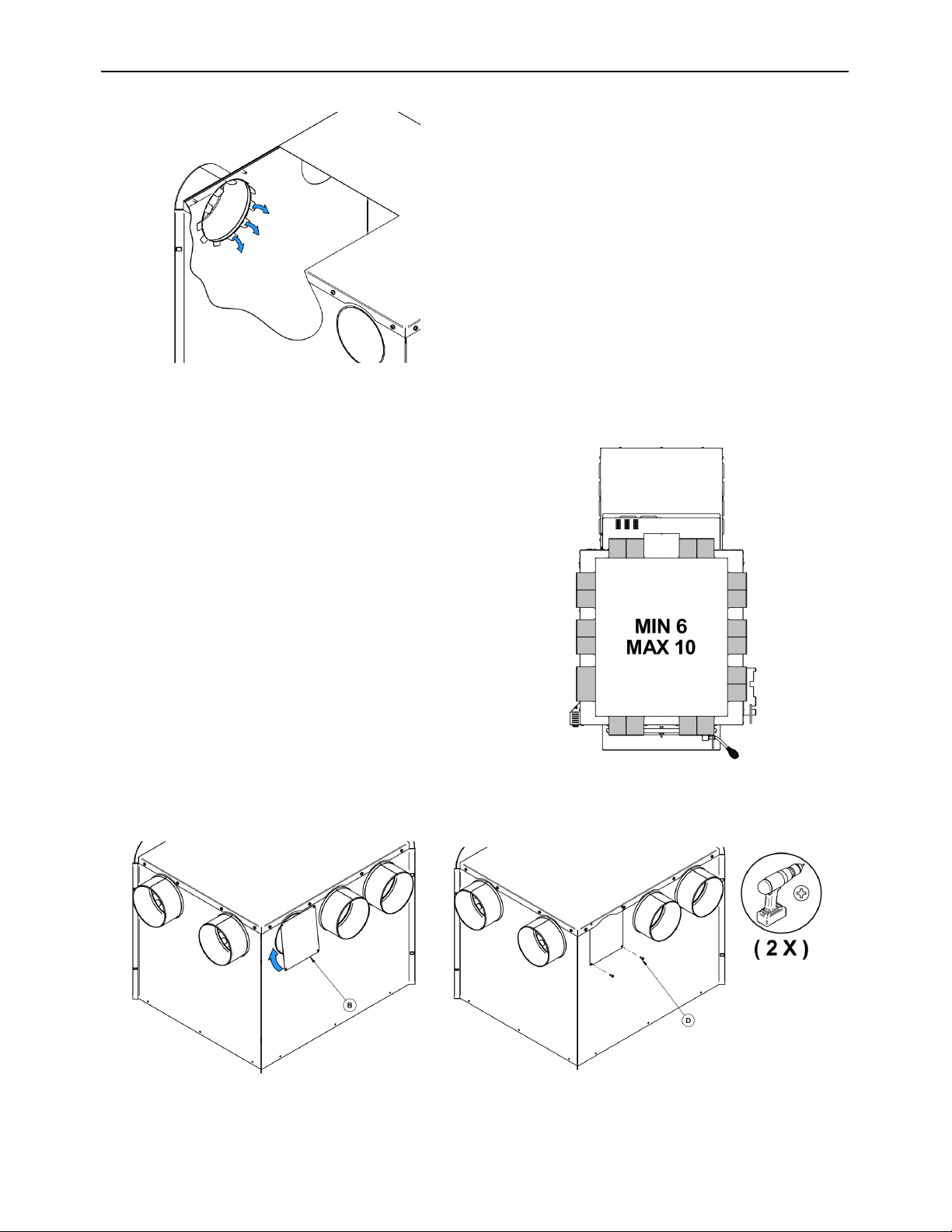
5.4.2 Installing the start-off adapters
After choosing your output configuration, do the following to install the start-off adapters.
Warning: Use gloves to complete the following steps because the start-off adapters
and caps can be sharp.
1- Position the start-off adapters in the
selected distribution hole.
2- Fold each tab of the adapter from the
inside of the plenum to immobilize the
adapter on the plenum.
3- Repeat 2 steps above to install other
adapters.
Heat Commander Furnace Installation and Operation Manual
29
5.4.3 Minimum number of outlets and maximum lengths of ducts
- A minimum of 6 start-off adapters must
be installed on the start-off plenum. The
location of the adapters has no impact
on the distribution of air.
- Block the unused outlets with the block-off caps (B) and provided screws (D). Insert
the block-off under the plenum top.
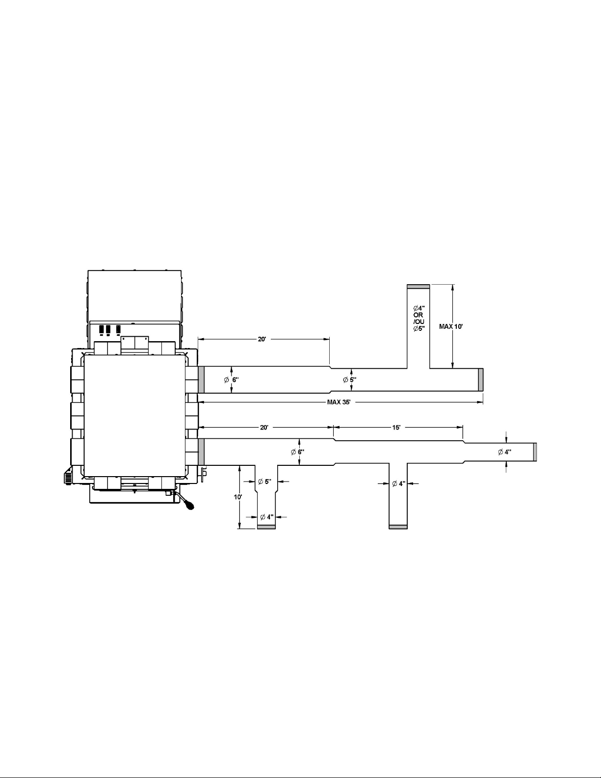
FAVOUR THE USE OF RIGID DUCTS BECAUSE THERE ARE LESS RESTRICTIVE TO
AIR FLOW.
- The maximum run of a main duct is 35’ (10.7 m). It must be reduced from 6" (152 mm)
to 5" (127 mm) after 20' (6.1 m) or reduce the main duct by 1" (25 mm) at every two
secondary duct outputs.
- The maximum length of all the main ducts is 180’ (54.9 m).
- The maximum run of a secondary duct is 10’ (3 m).
- The maximum length of all the secondary ducts is 100’ (30 m).
- The finishing grill at the output of a secondary pipe must be made of metal.
- Have a maximum of three secondary outputs per duct.
Note: figure for illustrative purposes only
For proper static pressure and heat distribution; the total area of secondary duct outlets must
be equal or slightly less than the total area of the outlets used on the distribution plenum (B).

Heat Commander Furnace Installation and Operation Manual
31
Example of surface calculation according to the number
of outlets used in the plenum:
Diameter of plenum
outlet (in)
Surface of plenum
outlet (in
2
)
Number of outlets
on the plenum
Total surface of
plenum outlets used
(in
2
)
6
28
6
170
The acceptable total area of secondary outlets would therefore be:
Diameter of
secondary outlet (in)
Surface of
secondary outlet
(in
2
)
Number of
secondary outlets
Total surface of
secondary outlets
used (in
2
)
4
12.5
9
112.5
5
19.5
1
19.5
6
28
1
28
The total area of the secondary outlets of this system would be
acceptable because it is equal to or slightly less than the total area
of the plenum outlets.
160
ACORDING TO THE NATIONAL BUILDING CODE, THE BTU/H PROVIDED BY AT
REGISTER MUST NOT EXCEED 10,250 BTU/H (3kW) AND THE HOT AIR
TEMPERATURE AT THE OUTLET OF A SECONDARY DUCT SHOULD NOT EXCEED
158 °F (70 °C).
Once your hot air distribution system is installed, make sure to measure the static pressure
in the start-off plenum. Adjust the opening at the end of each of distribution duct with a
shutter until you get a minimum static pressure 0.2” W.C. (50 Pa) at the plenum. The
recommended air velocity exiting the register should be between 500 and 750 feet per
minute.
5.5 Air return system and filter
The installation of an optional air return system connected to the blower housing will improve
the air circulation throughout the house (see Appendix 3: Optional Fresh air return
adapter (AC01392)). The use of the air filter option is recommended. The filter option will
significantly reduce dust circulation within the hot air duct and will prevent obstruction of the
blower (see Appendix 2: Optional air filters (AC01390, AC01391)).
NOTE: TO ENSURE ADEQUATE STATIC PRESSURE, THE SYSTEM SHOULD BE
BUILT IN A WAY THAT THE VOLUME OF COLD AIR RETURN IS AT LEAST EQUAL OR
SLIGHTLY HIGHER THAN THE VOLUME OF THE HOT AIR DISTRIBUTION.
6 Air Supply in Conventional Houses
The safest and most reliable supply of combustion air for a wood furnace is from the room
in which it is installed. Room air is already preheated so it will not chill the fire, and its
availability is not affected by wind pressures on the house.
Unlike commonly expressed concerns, almost all tightly sealed new houses have enough
natural leakage to provide a small amount of air needed by the furnace. The only case in
which the furnace may not have adequate access to combustion air is if the operation of a
powerful exhaust device (such as a kitchen range exhaust or air exchangers) causes the
pressure in the house to become negative relative to outdoors.
If an air fresh air supply is installed through the wall of the house, its pressure can vary
during windy weather. If there are changes in wood stove performance in windy weather,
and particularly if smoke puffs from the furnace, the air duct should be disconnected from
the stove to determine if it is the cause of the problem. In some windy conditions, negative
pressure at the duct weather hood outside the house wall may draw hot exhaust gases from
the furnace backwards through the duct to outdoors. Check the outdoor air duct for soot
deposits when the full system is cleaned and inspected at least once each year.
Additional combustion air can be provided following the following methods, provided that
they satisfy chapter 4 of the CSA B365 standard for Canada:
- Direct combustion air supply:
Heating units requires specific certification to be connected directly with fresh air supply.
The Heat Commander have been tested and is certified to be connected with direct
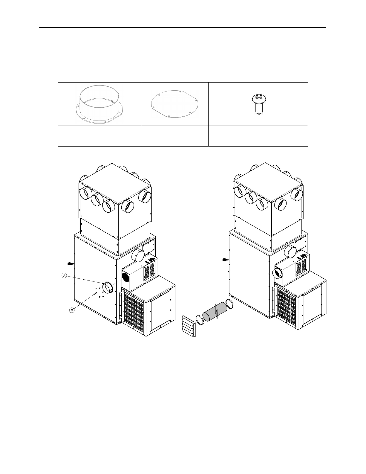
Heat Commander Furnace Installation and Operation Manual
33
combustion air. The fresh air supply adapter can be mounted on either side of the unit (left
or right) to allows you to choose the most convenient side.
Component provided with the furnace for the installation of a fresh air supply
1 Fresh air supply
adapter 5’’ (13 mm) (A)
1 Fresh air cover
(B)
12 Type A #10 black screws
(C)
- Indirect combustion air supply:
o New combustion air can be brought into a pipe located within approximately 12" (305
mm) of the unit. If the pipe is too close to the furnace, it may interfere with its
operation;
o The recommended diameter of the outside air intake pipe is 5" (127 mm);
o Mechanical ventilation system: if the house is equipped with a ventilation system (air
exchanger or heat recovery), the ventilation system may provide sufficient auxiliary
air to the furnace. Otherwise, the owner should be informed that the ventilation
system may have to be rebalanced by a ventilation technician after the installation of
the furnace.

7 Electrical connection and calibration of the draw
The furnace is fully assembled at the factory and no electrical connection is required
other than plugging the power cord into an outlet.
7.1 Electrical connections
The following instructions do not replace those of the local code.
Installation and verification of this appliance must be done by a qualified person.
All wiring from the service panel to the heating unit must comply with the electrical code in
force and all local regulations. It is recommended to feed the furnace with its own electrical
circuit of 15 amps at 120 volts with a breaker (see wiring diagram).
WARNING
ONLY USE WIRES SUITABLE FOR 167 °F (75 °C) OR MORE.
Heat Commander Furnace Installation and Operation Manual
35
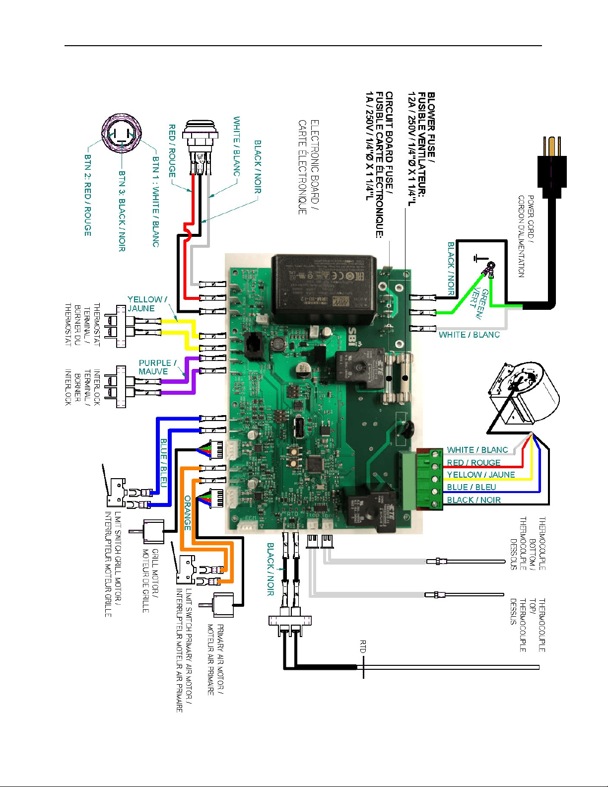
7.1.1 Electrical Diagram
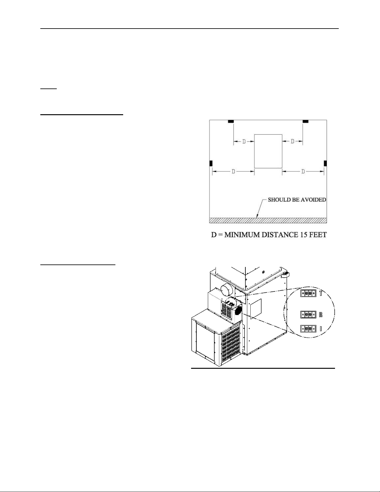
7.2 Furnace terminals identification
The furnace is equipped with three terminal blocks
located on the left rear of the furnace. They are
identified by the following three letters: T, R and I.
T : Thermostat
R : RTD (plenum thermal probe)
I : Relais Interlock (parallel add-on)
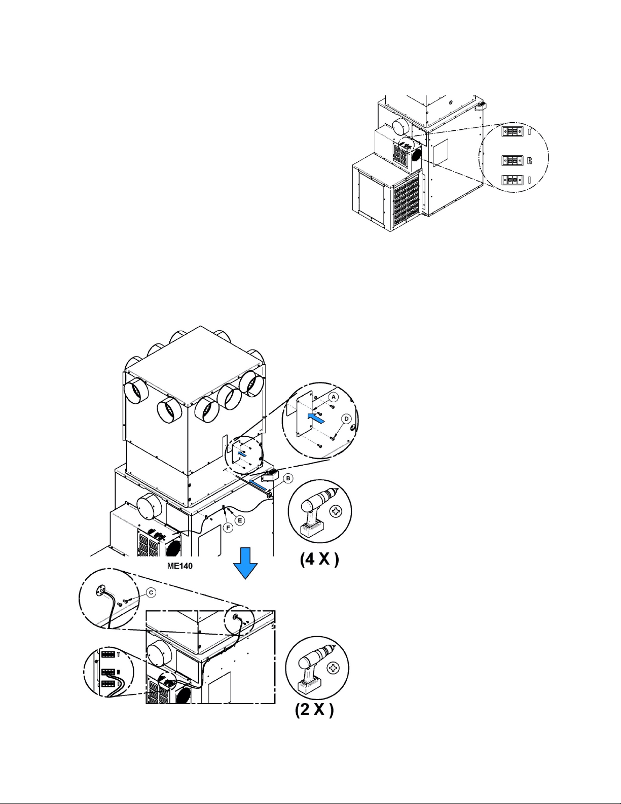
7.3 Installation and connection of the “RTD” thermal probe
IMPORTANT: The proper positioning of the “RTD” thermal probe is essential to the proper
functioning of the furnace. Install it in the opening provided for this purpose on the start-off plenum.
Install the RTD probe in the plenum
extension.
Secure the RTD probe with the two
screws provided (C).
Connect the RTD probe to the furnace
block terminal identified with a “R”.
Use the wire grommets (F) supplied
with the manual to attach the wires
from the RTD to the furnace.
Depending on the height of your
ceiling and the plenum adjustment,
the clearance hole in the top of the
plenum might create an air opening
in the plenum. In this case, install the
plate (A) provided with your plenum
kit and secure it with 4 self-drilling
screws (D) to seal the opening.
Heat Commander Furnace Installation and Operation Manual
37
7.4 Thermostat installation
Thermostat use will help you maintain a constant temperature throughout the house. A fixed
wall mounted 24v thermostat is required.
Note: Thermostat manufacturer’s instruction always overrides the information
published in the following section.
Thermostat location
- Must be installed on an inside wall of the
house;
- Where it will be the least affected by
affected by air currents from a hot air outlet
or cold outside walls;
- Must be installed at a minimum of 55" (140
cm) above the floor;
- Must be installed at a minimum of 15’ (4.57
m) from the furnace and must not receive
radiation heat from the glass door.
Thermostat wiring
Before installing the thermostat, disconnect
the furnace from the outlet.
Use an 18 AWG 2 strand wire.
The terminal block is located at the back on
the left side of the furnace when facing it. It
is identified with the letter “T”.
Loosen the two screws in the middle of the
terminal block and insert the wires in the
terminal. Tighten the two screws.
Open the thermostat housing and connect
the wires following the manufacturer's
instructions.
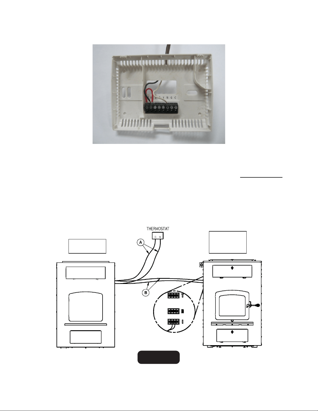
Example of thermostat wiring:
Connect one wire to "RH" and the other wire to "W". The red jumper can be left in place. For
more information, refer to the manufacturer's instructions.
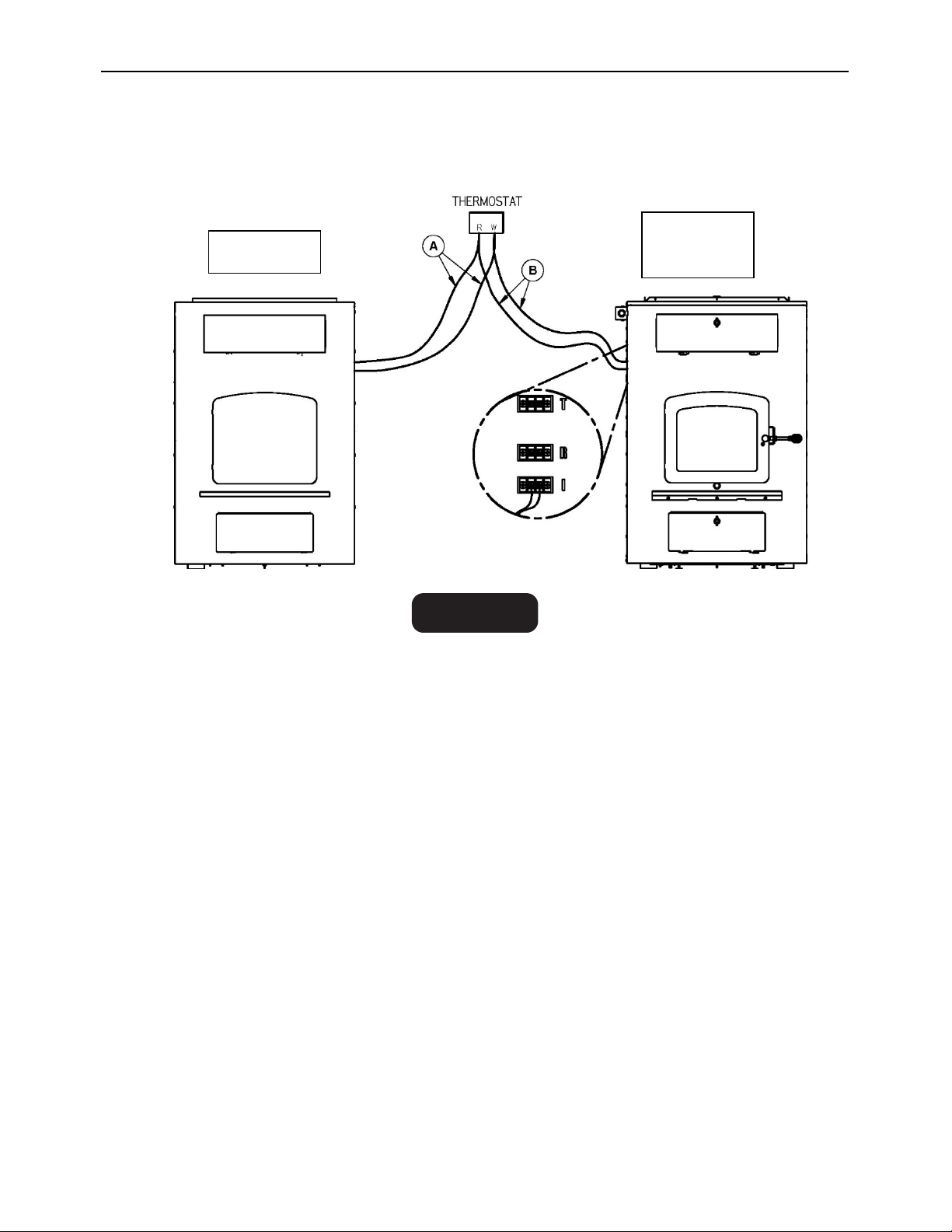
This furnace may be installed in parallel as an add-on to an existing furnace in the USA only.
Such an installation requires that the furnace’s controls be interlocked to prevent both
furnaces from heating at maximum rate simultaneously.
There are two ways to connect the existing thermostat to your device:
1- From the terminal of the existing furnace, connect 2 new wires (B) to the existing wire
(A) and fix them to the terminal identified "I" (interlock) of the parallel Add-On furnace.
USA only
EXISTING
FURNACE
PARALLEL
ADD-ON
FURNACE
Heat Commander Furnace Installation and Operation Manual
39
2- From the thermostat connected to the existing furnace, connect 2 new wire (B) on the R
and W terminals of your thermostat and fix them to the terminal identified "I" (interlock) of
the parallel Add-On furnace.
When the wood furnace receives the signal from the existing furnace thermostat calls for
heat, combustion air controls will close slowly, the wood furnace burn rate will reduce to is
minimum. After the existing furnace thermostat is satisfied, the wood furnace will return
under the control of its own thermostat.
USA only
EXISTING
FURNACE
PARALLEL
ADD-ON
FURNACE
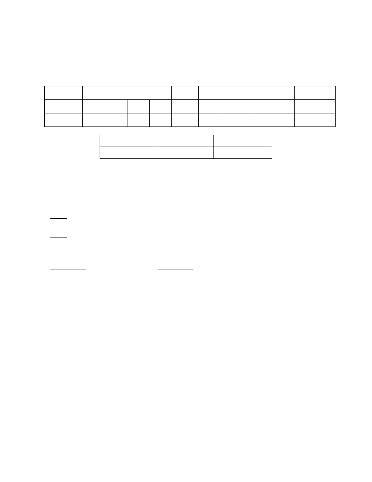
7.5 Blower technical Data
The blower speed must conform to the recommendations of the Warm Air Heating and Air
Conditioning National Association and should respect the static pressure ranges in the warm
air plenum of the furnace.
MODEL
(DIRECT DRIVE)
FLOW*
TEMP
VAR*.
BTU/ H
STATIC
PRESSURE
OPTIONAL
FILTER
VENT
MOT.
VIT.
(CFM)
(°F)
(WOOD)
INCH OF
W.C. / Pa
(IN)
Heat
Commander
DD-10
1/3
1
875
55
55 000
0,2 / 50
20" x 15" x 1"
Volts
Max Amps
Hertz
120
5
60
* These values may vary depending on installation, fuel, static pressure and use.
7.6 Draft Calibration
The draft: The measurement is taken in the exhaust pipe 18" (457 mm) above the furnace's
flue collar with a tube and a pressure gauge (manometer).
- Poor: -0.03" W.C. (7.5 Pa) and under: ignition problems, risk of smoke spillage, low
performance of heat exchangers.
- Ideal: from -0.04" to -0.06" W.C. (10 to 15 Pa): to obtain the optimum performance of
the furnace.
o A barometric draft control is not required.
- Excessive: -0.08" W.C. (20 Pa): WARNING
This leads to premature wear of the furnace, a situation that is not covered by warranty.
o A draft greater than -0.08" W.C. (20 Pa) leads to uncontrollable fire even if the air
control is in closed position.
o The self-regulating furnace control system reduces the risk of excessive draft. If
necessary, a barometric control must be installed to control excessive draft. It
must be adjusted to limit the maximum draft to -0.06 in W.C. (15 Pa).
Heat Commander Furnace Installation and Operation Manual
41
7.6.1 The use of a stove thermometer
The first use of a thermometer is to inform the user about the discharge temperature of flue
gases. Without accurate measurement of the draft using a pressure gauge (manometer),
the thermometer will indicate if the temperature is ideal, too low or too high.
The use of e thermometer is therefore an acceptable alternative that can tell if the chimney
is hot enough to generate an adequate draft.
- Use a magnetic thermometer for Single wall connector pipe.
- Use a probe thermometer for Double wall connector pipe.
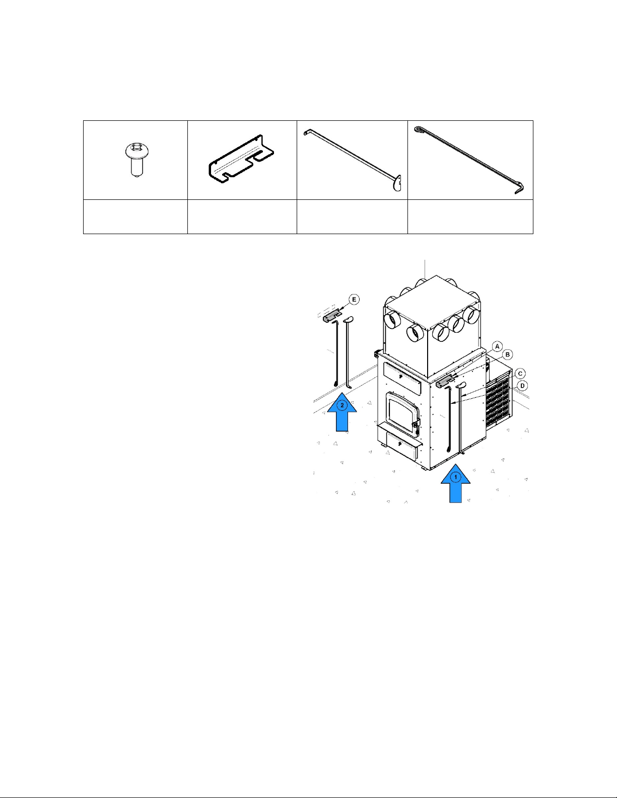
8 Tool Holder Installation
Components supplied with the device for the installation of the holder:
Type A #10
black screws (A)
Tool Holder (B)
Heat Exchanger
Scraper(C)
Poker (D)
The tool holder can be installed on the right
side of the furnace (1) or on a wall (2) near
your furnace. For installation on a wall, use
two E screws appropriate for the material to
which the holder will be attached.
Heat Commander Furnace Installation and Operation Manual
43
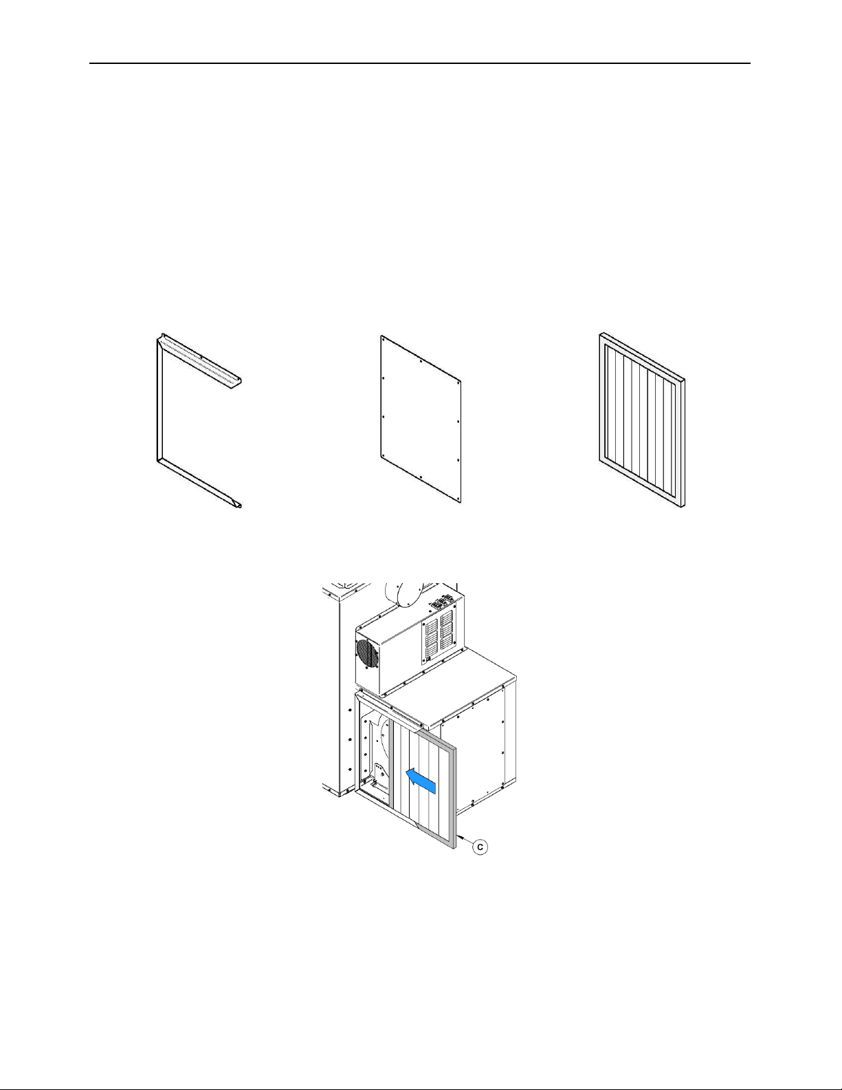
Appendix 1: Optional air filters (AC01390, AC01391)
The filter option (AC01390 – cardboard frame or AC01391 – washable aluminum) allows
filtrating dirt before distribution warm air in your installation in addition of protecting your
blower. This system can be installed on either sides of the blower box located behind the
furnace on the most convenient of your installation. This option includes the filter, the filter
holder, two caps and the screws necessary for the installation.
Clean and replace filters as often as required.
Note: The operation cost is higher and the overall efficiency is reduced when using a
dirty filter.
1 filter holder
2 caps
1 filter (15" x 20" x 1")
WARNING: IT IS NOT RECOMMENDED TO OPERATE THE FURNACE WITHOUT
FILTERS. THIS APPLIES ESPECIALLY TO TEMPORARY HEATING DURING
CONSTRUCTION PERIOD. OPERATING THE FURNACE WITHOUT FILTERS WOULD
ALLOW DUST AND OTHER PARTICLES IN THE AIR TO CIRCULATE FREELY AND TO
PENETRATE INTO THE BLOWER AND MOTOR CARTERS, CAUSING SOME
DEFECTS.
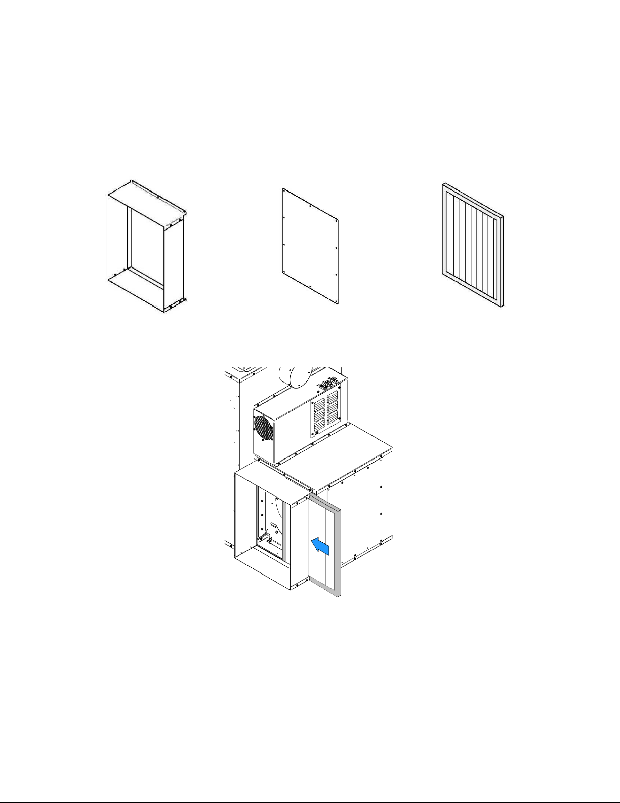
Appendix 2: Optional air return adapter (AC01392)
The optional air return adapter (AC01392) can be added to the furnace blower box to
increase the efficiency of your system. This option allows you to take in the fresh air from
the rooms connected to the return system and bring it back towards the furnace to be heated.
This option can be installed on either sides of the blower box. Complete installation
instruction can be found in the instruction booklet provided when purchasing this option.
1 air return adapter
2 caps
1 filter
N.B.: TO ENSURE ADEQUATE STATIC PRESSURE, THE SYSTEM SHOULD BE BUILT
IN A WAY THAT THE VOLUME OF COLD AIR RETURN IS AT LEAST EQUAL OR
SLIGHTLY HIGHER THAN THE VOLUME OF THE HOT AIR DISTRIBUTION.
Heat Commander Furnace Installation and Operation Manual
45
PART B –
OPERATION, MAINTENANCE AND TROUBLESHOOTING
8.1 How to prepare or buy good firewood
8.1.1 What is good firewood?
Good firewood has been cut to the correct length for the furnace, split to a range of sizes
and stacked in the open until its moisture content is reduced to 15% to 20%.
8.1.2 Tree species
The tree species the firewood is produced from is less important than its moisture content.
The main difference in firewood from various tree species is the density of the wood.
Hardwoods are denser than softwoods. People who live in the coldest regions of North
America usually have only spruce, birch and poplar, other low-density species to burn and
yet they can heat their homes successfully.
Homeowners with access to both hardwood and softwood fuel sometimes use both types
for different purposes. For example, softer woods make good fuel for relatively mild weather
in spring and fall because they light quickly and produce less heat Softwoods are not as
dense as hardwoods, so a given volume of wood contains less energy. Using softwoods
avoids overheating the house, which can be a common problem with wood heating in
moderate weather. Harder woods are best for colder winter weather when more heat and
longer burn cycles are desirable.
Note that hardwood trees like oak, maple, ash and beech are slower growing and longer
lived than softer woods like poplar and birch. That makes hardwood trees more valuable.
The advice that only hardwoods are good to burn is outdated. Old, leaky cast iron furnaces
would not hold a fire overnight unless they were fed large pieces of hardwood. That is no
longer true. You can successfully heat your home by using the less desirable tree species
and give the forest a break at the same time.
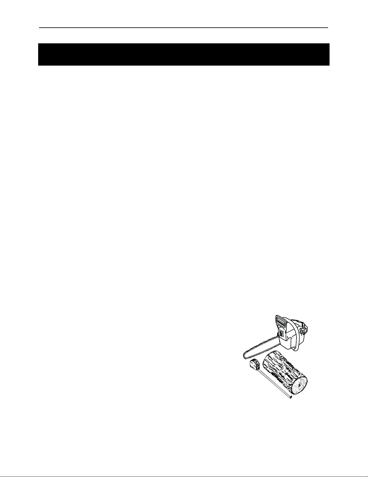
8.1.3 Log length
Logs should be cut about 1" (25 mm) shorter than the
firebox so they fit in easily. Pieces that are too long make
loading the furnace very difficult. The most common
standard length of firewood is 16" (406 mm).
The pieces should be a consistent length, with a
maximum of 1" (25 mm) variation from piece to piece.
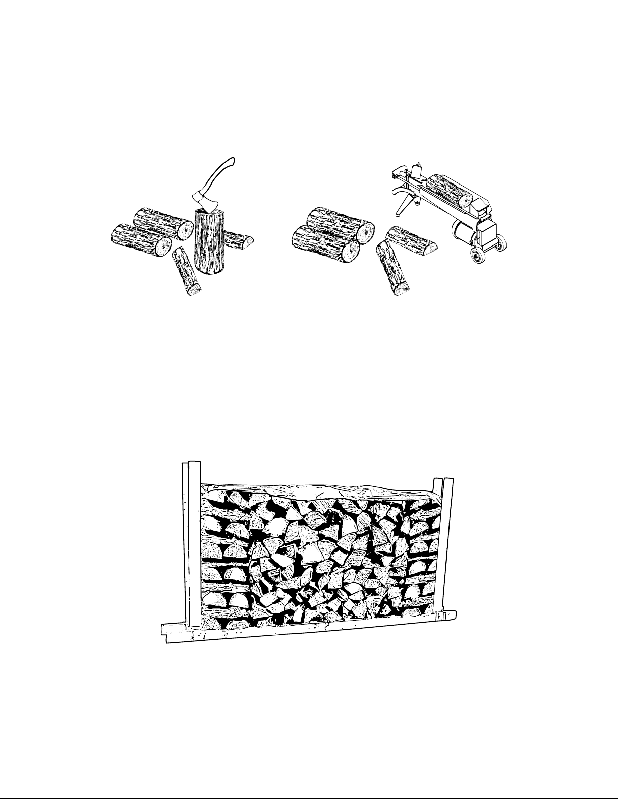
8.1.4 Piece size
Firewood dries more quickly when it is split. Large unsplit rounds can take years to dry
enough to burn. Even when dried, unsplit logs are difficult to ignite because they don’t have
the sharp edges where the flames first catch. Logs as small as 3" (76 mm) should be split
to encourage drying.
Wood should be split to a range of sizes, from about 3" to 6" (76 mm to 152 mm) in cross
section. Having a range of sizes makes starting and rekindling fires much easier. Often, the
firewood purchased from commercial suppliers is not split finely enough for convenient
stoking. It is sometimes advisable to re-split the wood before stacking to dry.
8.1.5 How to dry firewood
Firewood that is not dry enough to burn is the cause of most complaints about wood burning
appliances. Continually burning green or unseasoned wood produces more creosote and
involves lack of heat and dirty glass door. See Section 10: Maintaining your wood heating
system for concerns about creosote.
Heat Commander Furnace Installation and Operation Manual
47
Here are some things to consider in estimating drying time:
• firewood takes a long time to dry
• firewood bought from a dealer is rarely dry enough to burn, so it is advisable to buy the
wood in spring and dry it yourself
• drying happens faster in dry weather than in damp, maritime climates
• drying happens faster in warm summer weather than in winter weather
• small pieces dry more quickly than large pieces
• split pieces dry more quickly than unsplit rounds
• softwoods take less time to dry than hardwoods
• softwoods like pine, spruce, and poplar/aspen can be dry enough to burn after being
stacked in the open for only the summer months
• hardwoods like oak, maple and ash can take one, or even two years to dry fully,
especially if the pieces are big
• firewood dries more quickly when stacked in the open where it is exposed to sun and
wind; it takes much longer to dry when stacked in a woodshed
• firewood that is ready to burn has a moisture content between15 and 20% by weight and
will allow your furnace to produce its highest possible efficiency
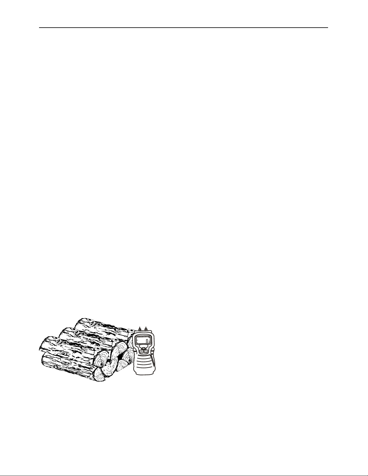
8.1.6 Judging firewood moisture content
You can find out if some firewood is dry enough to burn by using these guidelines:
• Use the wood moisture meter provided with your furnace to test your firewood. Testing
the middle of a freshly split piece of wood is the most accurate test point,
• cracks form at the ends of logs as they dry,
• as it dries in the sun, the wood turns from white or cream colored to grey or yellow,
• bang two pieces of wood together; seasoned wood sounds hollow and wet wood sounds
dull,
• dry wood is much lighter in weight than wet wood,
• split a piece, and if the fresh face feels warm and dry it is dry enough to burn; if it feels
damp, it is too wet,
• burn a piece; wet wood hisses and sizzles in the fire and dry wood does not.

9 Operating your furnace
9.1 How it works
The Heat Commander furnace is equipped with a self-regulated combustion air supply
control system. Using two temperature sensors in the combustion chamber that measure
the temperature in real time, your furnace will automatically adjust the amount of combustion
air required for the cleanest and most efficient combustion.
Coupled with the thermostat, the furnace will automatically modulate the combustion rate
according to the thermostatic demand. When the thermostat calls for heat, combustion will
be at its maximum burn rate. Conversely, when the thermostat is satisfied with heat, the
combustion burn rate will be slowed down to maximum.
A third temperature sensor located in the plenum controls the air distribution fan. This will
distribute the necessary heat in your ducts to satisfy the thermostat while maintaining a
safe temperature in your heating system.
Heat Commander Furnace Installation and Operation Manual
49
9.2 How Reload Button Works
The furnace is equipped with a backlit reload button located at the front. To optimize
combustion during ignition and reloading, it is necessary to press the reload button. When
you press the button, it will flash rapidly three times. Automatically the combustion air supply
will be increased to its maximum, thus the ignition of the charge and the recharge will be
facilitated.
The button indicator light indicates the status of your furnace according to the thermostatic
demand and the available heat. See the table below for details of each state.
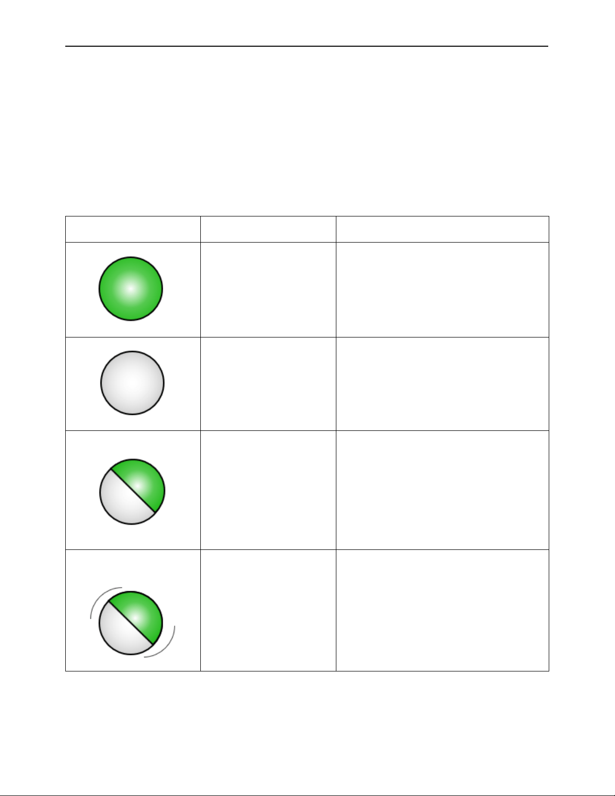
Led button states
Meaning
Furnace status
Light is ON
The thermostat calls for heat and
there is heat available in the
combustion chamber.
Maximum energy:
The furnace goes to maximum
burn rate and attempts to provide maximum heat
while maintaining clean and efficient combustion.
The fan blows at normal speed.
Light is OFF
The furnace is cold. (Does not
consider the state of the
thermostat)
Low energy:
The furnace is cold; it needs to be lit with
paper and kindling to provide heat.
Light blinking slowly (1.5
second per blink)
The thermostat does not call for
heat and there is heat available in
the combustion chamber.
Energy saving:
The furnace burns to a minimum burn
rate and distributes as little heat as possible through
the distribution air ducts to save wood by maintaining
clean and efficient combustion. The fan cycles to
remove excess heat.
Light blinking quickly (5
blinks per second):
The furnace has reached its
maximum temperature.
Thermal protection:
The furnace control system
reduces to minimum the supply of combustion air. If
firebox maximum temperature is reached, fan will
blow at normal speed. If plenum maximum
temperature is reached, fan will blow at maximum
speed.
DO NOT ADD WOOD
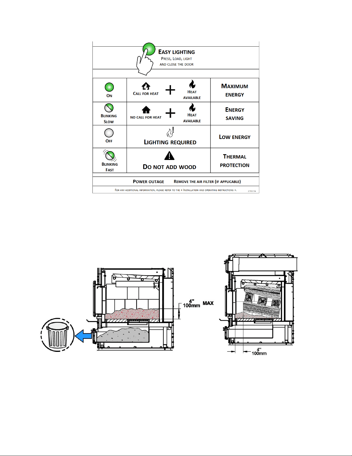
9.3 How to light and reload the furnace
Note: Always keep a maximum of 4 inches of ash in the firebox. Weekly empty the ash
drawer to ensure the correct operation of the furnace. For a clean and efficient combustion
always keep some space between the logs and leave at least 4 inches of space in front of
the logs.
.
Heat Commander Furnace Installation and Operation Manual
51
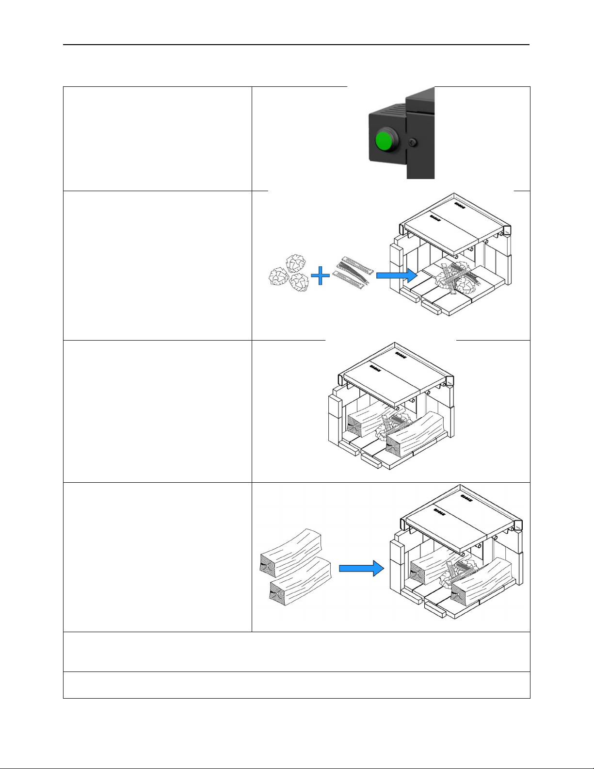
9.3.1 Cold start and cold ember bed (The led button light is OFF)
• Press reload button before
opening the door
• Place paper and kindling
on top of the ash grate
• Place two logs
North&South on each side
of the kindling
• Place another row in a
crisscross pattern on top of
the first logs.
• Light the paper and leave the door ajar (45 degree). Wait until the kindling and the
logs catch fire. Then close the door.
• Important: never leave unattended the furnace with the door opened.
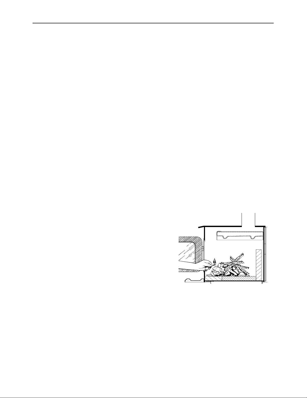
9.3.2 Hot ember bed reload (The led button light is ON or slowly blinking)
• Press reload button before
opening the door.
• Open the door and bring
hot embers to the front.
• Load two logs
North&South at the back.
Crisscross logs over.
Always leave 4” of free
space in the front.
• Leave the door ajar(45 degree) until the first flames appear. Then close the door.
• Important: never leave unattended the furnace with the door opened.
Heat Commander Furnace Installation and Operation Manual
53
9.4 Your first fires
Two things will happen when burning the first few fires; the paint cures and the internal
components of the furnace are conditioned.
As the paint cures, some of the chemicals vaporize. The vapors are non-toxic, but they do
smell bad. Fresh paint fumes can also cause false alarms in smoke detectors.
So, when lighting the furnace, be prepared by opening doors or windows to ventilate the
house. Burn one or two small fires to begin the curing and conditioning process. Then build
bigger and hotter fires until there is no longer paint smell from the furnace.
As hotter and hotter fires are burnt, more of the painted surfaces reach the curing
temperature of the paint. The smell of curing paint does not disappear until one or two very
hot fires have been burnt.
9.5 Lighting fires
Each person who heats with wood develops their own favorite method to light fires.
Whatever method you choose, your goal should be to get a hot fire burning quickly. A fire
that starts fast produces less smoke and deposits less creosote in the chimney.
Here are three popular and effective ways to start wood fires.
9.5.1 Conventional fire starting
The conventional way to build a wood fire is to
bunch up 5 to 10 sheets of plain newspaper and
place them in the firebox. Next, place 10 or so
pieces of fine kindling on the newspaper. This
kindling should be very thin; less than 1” (25 mm).
Next, place some larger kindling pieces on the fine
kindling. Press the reload button, light the
newspaper. If you have a tall, straight venting
system you should be able to close the door
immediately. If your venting system has elbows or
an outside chimney, you may need to leave the
door ajar for a few minutes as the newspaper
ignites and heat in the chimney produces some
draft. Once the fire has ignited, close the door.
A conventional kindling fire with
paper under finely split wood.
DO NOT LEAVE THE FURNACE UNATTENDED WHEN THE DOOR IS SLIGHTLY
OPENED DURING LIGHTING. ALWAYS CLOSE THE DOOR AFTER LIGHTING.
After the kindling fire has mostly burned, you can add firewood pieces until you have a fire
of the right size for the conditions.

9.5.2 The top down fire
The top down fire starting method solves two problems with the conventional method: first,
it does not collapse and smother itself as it burns; and second, it is not necessary to build
up the fire gradually because the firebox is loaded before the fire is lit. A top down fire can
provide up to two hours of heating or more. The top down method only works properly if the
wood is well-seasoned.
Start by placing three or four full-sized split pieces of dry firewood in the firebox. Next, place
4 or 5 more finely split pieces of firewood (2" to 3" (51 mm to 76 mm) diameter) on the base
logs at right angles (log cabin style). Now place about 10 pieces of finely split kindling on the
second layer at right angles.
The fire is topped with about 5 sheets of newspaper. You can just bunch them up and stuff
them in between the kindling and the underside of the baffle. Or you can make newspaper
knots by rolling up single sheets corner to corner and tying a knot in them. The advantage
of knots is that they do not roll off the fire as they burn. Light the newspaper and watch as
the fire burns from top to bottom.
9.5.3 Two parallel logs
Place two spit logs in the firebox. Place a few sheets of twisted newspaper between the logs.
Now place some fine kindling across the two logs and some larger kindling across those,
log cabin style. Light the newspaper.
9.5.4 Using fire starters
Commercial fire starters can be used instead of a newspaper. Some of these starters are
made of sawdust and wax and others are specialized flammable solid chemicals. Follow the
package directions for use.
Gel starters can also be used, but only to light a fire, in a cold combustion chamber without
hot embers inside.
9.6 Maintaining wood fires
9.6.1 General advice
Wood heating is very different than other forms of heating.
Do not expect steady heat output from your furnace. It is normal for its temperature to rise
after a new load of wood is ignited and for its temperature to gradually decline as the fire
progresses. This rising and falling of temperature can be matched to your household
routines. For example, the area temperature can be cooler when you are active, such as
when doing housework or cooking, and it can be warmer when you are inactive, such as
when reading or watching television.
Wood burns best in cycles. A cycle starts when a new load of wood is ignited by hot coals
and ends when that load has been consumed down to a bed of charcoal about the same
size as it was when the wood was loaded. Do not attempt to produce a steady heat output
by placing a single log on the fire at regular intervals. Always place at least three, and
preferably more, pieces on the fire at a time so that the heat radiated from one piece helps
to ignite the pieces next to it. Each load of wood should provide several hours of heating.
The size of each load can be matched to the amount of heat needed.
Heat Commander Furnace Installation and Operation Manual
55
When you burn in cycles, you rarely need to open the furnace’s loading door while the wood
is burning. This is an advantage because there is more chance that smoke will leak from the
furnace when the door is opened as a full fire is burning. This is especially true if the chimney
connector has 90 degree elbows and if the chimney runs up the outside wall of the house.
IMPORTANT
WHEN RELOADING, MAKE SURE YOU KEEP THE AIR INLETS LOCATED AT THE
BOTTOM OF THE DOOR INSIDE THE COMBUSTION CHAMBER FREE OF ASH.
OPENING PROCEDURE FOR THE LOADING DOOR
TO MINIMISE THE RISK OF SMOKE SPILLAGE, CRACK THE DOOR OPEN ABOUT AN
INCH (25 MM) AND WAIT ABOUT 10 SECONDS BEFORE OPENING IT WIDE TO
ALLOW STABILISATION OF THE PRESSURE INSIDE THE FURNACE.
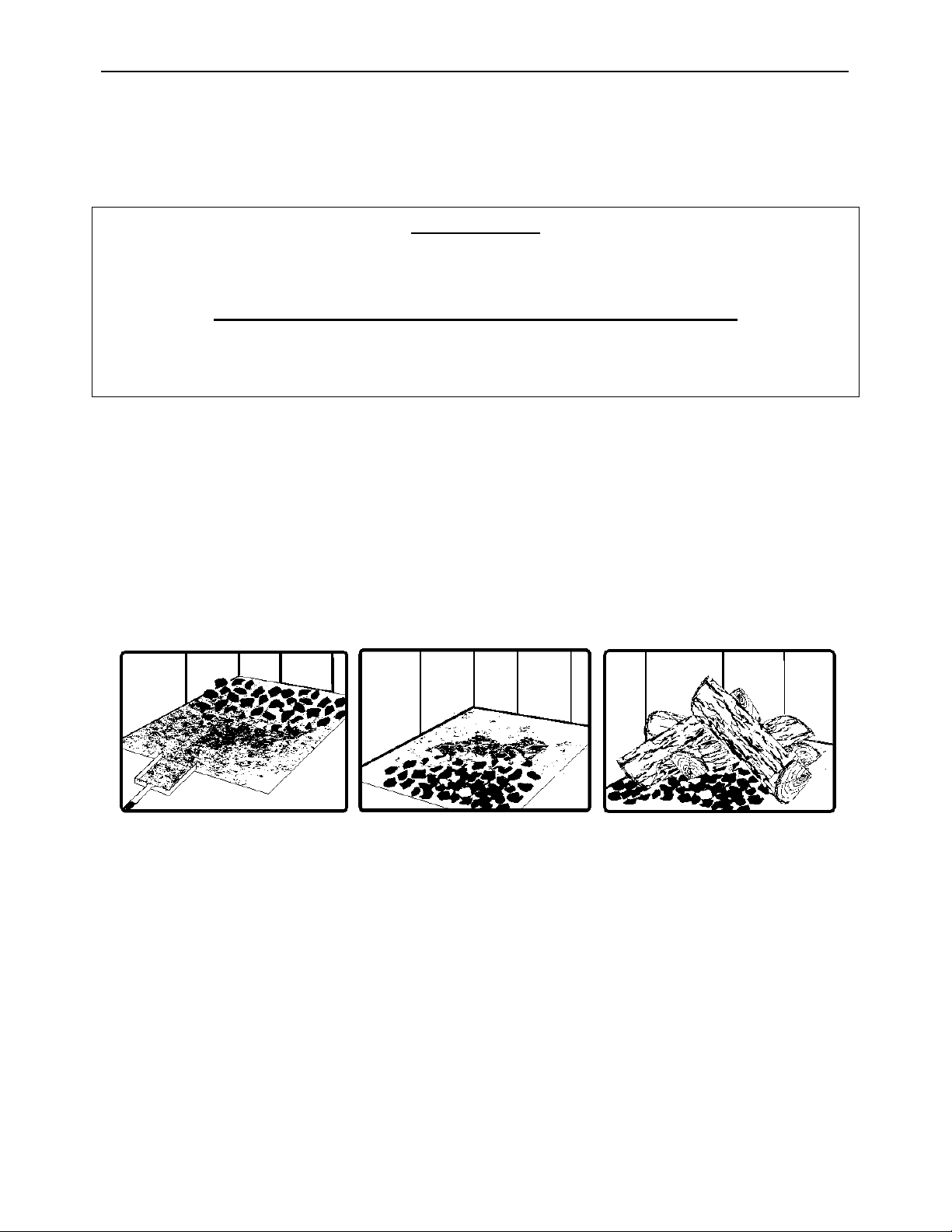
9.6.2 Raking charcoal
Rekindle the fire when you notice that the room temperature has fallen. Do not operate your
furnace at too low a setting. Keep the air inlet opened long enough during the fire start-up
to prevent the fire from smouldering, which could stain the glass. You will find most of the
remaining charcoal at the back of the firebox, furthest from the door. Rake these coals
towards the door before loading. There are two reasons for this raking of the coals. First, it
concentrates them near where most of the combustion air enters the firebox and where they
can ignite the new load quickly, and second, the charcoal will not be smothered by the new
load of wood. If you were to simply spread the charcoal out, the new load will smoulder for
a long time before igniting.
Remove ash first, and then rake charcoal towards the front of the firebox before loading so
that it will ignite the new load.

9.6.3 Firing Each New Load Hot
Press the reload button, place the new load of wood on and behind the charcoal. Close the
door. Firing each load of wood hot accomplishes a few things:
• drives the surface moisture from the wood,
• creates a layer of char on the wood, which slows down its release of smoke,
• heats the firebox components so they reflect heat back to the fire, and
• heat the chimney so it can produce strong, steady draft for the rest of the cycle.
DO NOT LEAVE THE FURNACE UNATTENDED WHILE A NEW LOAD IS BEING FIRED
HOT.
DO NOT OVERFIRE.
When you burn a new load of wood hot to heat up the wood, the furnace and the chimney,
the result will be a surge of heat from the furnace. This heat surge is welcome when the
room temperature is a little lower than desirable, but not welcome if the space is already
warm. Therefore, allow each load of wood to burn down so that the space begins to cool off
a little before loading.
9.6.4 Control of the air supply
Once the firewood, firebox and chimney are hot, the air combustion controls will close
gradually to maintain the optimal combustion chamber temperature.
9.6.5 Building different fires for different needs
Your house will need far less heat in October than in January to be kept at a comfortable
temperature. If you fill the firebox full in fall weather, you will either overheat the space or
turn the furnace down so much that the fire will be smoky and inefficient. Here are some
suggestions for building fires to match different heat demand.
9.6.5.1 Small fires to take the chill off the house
To build a small fire that will produce a low heat output, use small pieces of firewood and
load them crisscross in the firebox. The pieces should be only 3” (76 mm) to 4” (102 mm) in
diameter. After raking the coals, you can lay two pieces parallel to each other corner to
corner in the firebox and lay two more across them in the other direction. This kind of fire is
good for mild weather when you are around to tend the furnace and should provide enough
heat for four hours or more. Small fires like this are a good time to use softer wood species
so there will be less chance of overheating the house.
9.6.5.2 Long lasting low output fires
Sometimes you will want to build a fire to last up to eight hours, but do not need intense
heat. In this case use soft wood species and place the logs compactly in the firebox so the
pieces are packed tightly together.
Heat Commander Furnace Installation and Operation Manual
57
9.6.5.3 High output fires for cold weather
When the heat demand is high during cold weather, you will need a fire that burns steadily
and brightly. This is the time to use your biggest pieces of hardwood fuel if you have it. Put
the biggest pieces at the back of the firebox and place the rest of the pieces compactly. A
densely built fire like this will produce the longest burn your furnace is capable of.
9.6.5.4 Maximum burn cycle times
The burn cycle time is the period between loading wood on a coal bed and the consumption
of that wood back to a coal bed of the same size. The flaming phase of the fire lasts for
roughly the first half of the burn cycle and the second half is the coal bed phase during which
there is little or no flame. The length of burn you can expect from your furnace, including
both the flaming and coal bed phases, will be affected by several things, such as:
• firebox size,
• the amount of wood loaded,
• the species of wood you burn,
• the wood moisture content,
• the size of the space to be heated,
• the climate zone you live in, and
• the time of year.
• the time cycle for the thermostat to call for heat.
The table below provides a very general indication of the maximum burn cycle times you are
likely to experience, based on firebox volume.
FIREBOX VOLUME
MAXIMUM
BURN TIME
< 1.5 ft
3
3 to 5 hours
1.5 ft
3
to 2 ft
3
5 to 6 hours
2 ft
3
to 2.5 ft
3
6 to 8 hours
2.5 ft
3
to 3.0 ft
3
8 to 9 hours
>3.0 ft
3
9 to 10 hours
9.7 Additional fresh air supply
When the furnace and the chimney are completely cold, it may be necessary to provide fresh
air by opening a door or a window for a few minutes while lighting the fire.
Take note that a house constructed or renovated to be airtight may lack the volume of fresh
air necessary for the proper combustion of a solid-fuel heating appliance.
In such a case, when starting up the fire, do not operate appliances that evacuate air outside
the house, such as:
• Range hood
• Air exchanger
• Clothes dryer
• Bathroom blower
• Ventilated central vacuum system

Exhaust blowers that are in a fuel storage room should be installed so as not to create
negative pressure in the room where the solid fuel appliance is located.
A fresh air supply may be necessary to prevent furnace from rejecting products of
combustion into the house. The indications used to determine if an additional fresh air supply
is necessary are not appropriate for all the situations. When in doubt, it is recommended to
install a fresh air supply.
A fresh air supply may be needed if:
- Solid fuel units present anomalies, such as irregular draft, smoke return, bad combustion,
and/or reversed draft (whether there is combustion or not);
- Existing units such as a stove, a furnace or fireplace release odours, heat badly, cause
smoke returns, or reversed draft (whether there is combustion or not );
- The opening of a window, even slightly, in calm weather (windless), eliminates every
problem mentioned above ;
- The house is equipped with a tight vapour/air barrier and adjusted windows, and/or is
equipped with an interior air mechanical evacuation device ;
- There is excessive condensation on the windows in winter; and
- The house is equipped with a ventilation system.
If, according to these symptoms or other similar ones, there is insufficient combustion air, it is
necessary to ensure an additional combustion air supply (see Section 6: Air Supply in
conventional houses).
9.8 Ash drawer
Your furnace is equipped with an ash drawer to collect ashes produced by the combustion
of wood. The ash drawer is provided with one (1) wing nut to hold the door in a close position.
Operating the furnace with the ash drawer open may cause overfiring and damage the
furnace. The drawer must be emptied weekly.
9.9 Prolonged power outage
To reduce the risk of overheating during a prolonged power outage (more than 10 minutes),
the combustion air controls will be closed automatically. If your furnace is equipped with the
optional filter, remove the air filter to improve the circulation of air around the combustion
chamber of the furnace. Do not load the furnace more than 50 percent of its capacity to
prevent the risk of overheating,

Heat Commander Furnace Installation and Operation Manual
59
10 Maintaining your wood heating system
10.1 Furnace maintenance
Your new furnace will give many years of reliable service if you use and maintain it correctly.
Some of the internal components of the firebox, such as firebricks, baffles and air tubes, will
wear over time under intense heat. You should always replace defective parts with original
parts (see Section 12: Exploded diagram and parts list). For firing each load hot to begin
a cycle as described above will not cause premature deterioration of the furnace. However,
if the thermostat always calls for heat it can cause damage over time. The more the furnace
overheats during combustion cycles, the faster its elements will deteriorate. For that reason,
never leave the furnace unattended while a new load is being fired hot.
Recommended Maintenance Scheduled
Use this as a guide when used under average conditions.
Components
Weekly
or after
± 1/3 Face
cord
Monthly
± 1 Face cord
Annually
or
± 3 Face cord
Glass
Inspect and
Clean*
Combustion Chamber
Empty /
Vacuum*
Inspect
Ash drawer
Empty*
Air filter (If applicable)
Clean or replace every
three months
Firebricks
Inspect
Baffle
Inspect
Air tube
Inspect
Heat Exchanger
Inspect, Sweep and Clean*
Door tightness
Inspect and adjust or
replace gasket if necessary
Thermocouples
Inspect and Clean
Chimney
Sweep and Clean if
necessary*
Blower
Clean
Face cord; 4’X8’X16’’ (≈42 cubic feet)
*Cleaning frequency may vary depending on the type of fuel used. Fuel with higher ash
content will increase cleaning frequency.

CAUTION: IT IS RECOMMENDED TO CLEAN THE HEAT EXCHANGERS, FLUE PIPE AND
CHIMNEY THOROUGHLY AT THE END OF THE HEATING SEASON IN ORDER TO PREVENT
CORROSION DURING THE SUMMER MONTHS, CAUSED BY ACCUMULATED ASH AND/OR
SOOT AND/OR CREOSOTE.
10.1.1 Ash removal
Ash should be removed from the firebox every week of full time heating. Do not let the ash
build up in the firebox because it will interfere with proper fire management.
The best time to remove ash is after an overnight fire when the furnace is relatively cool, but
there is still some chimney draft to draw the ash dust into the furnace and prevent it from
coming into the room.
After ashes have been removed from the furnace and placed in a tightly covered metal
container, they should be taken outside immediately. The closed container of ashes should
be placed on a non-combustible floor or on the ground well away from all combustible
materials pending final disposal. Ashes normally contain some live charcoal that can stay
hot for several days. If the ashes are disposed of by burial in soil or otherwise locally
dispersed, they should be retained in the closed container until all cinders have thoroughly
cooled. Other waste shall not be placed in this container.
NEVER STORE ASHES INDOORS OR IN A NON-METALIC CONTAINER OR ON A
WOODEN DECK. ALWAYS LEAVE THE CONTAINER ON A NON-COMBUSTIBLE
FLOOR.
10.1.2 Cleaning door glass
Under normal conditions, your door glass should stay relatively clear. If your firewood is dry
enough and you follow the operating instructions in this manual, a whitish, dusty deposit will
form on the inside of the glass after a week or so of use. This is normal and can be easily
removed when the furnace is cool by wiping with a damp cloth or paper towel and then
drying. Never attempt to clean the glass when the furnace is hot.
In spring and fall the furnace will cycle less often. You may see some light brown stains
forming, especially at the lower corners of the glass. This indicates that the combustion has
been incomplete and some of the smoke has condensed on the glass. When the weather is
mild, you may find that letting the fire go out is better than trying to maintain a continuous
fire. Use the technique described above for building a fire to take the chill off the house.
If you do get brown stains on the glass, you can remove them with special cleaners for wood
furnace glass doors. Do not use abrasives to clean your furnace’s door glass.
The deposits that form on the glass are the best indication of the quality of your fuel and how
well you are doing in operating the furnace. Your goal should be clear glass with no brown
stains. If you continue to see brown stains on the glass, something about your fuel and
operating procedure needs to be changed. Stains on the glass indicate incomplete
combustion of the wood, which also means more smoke emissions and faster formation of
creosote in the chimney.
When brown streaks are coming from the edge of the glass, it is time to replace the gasket
around the glass. The glass gasket should be self-adhesive. Follow the instructions in
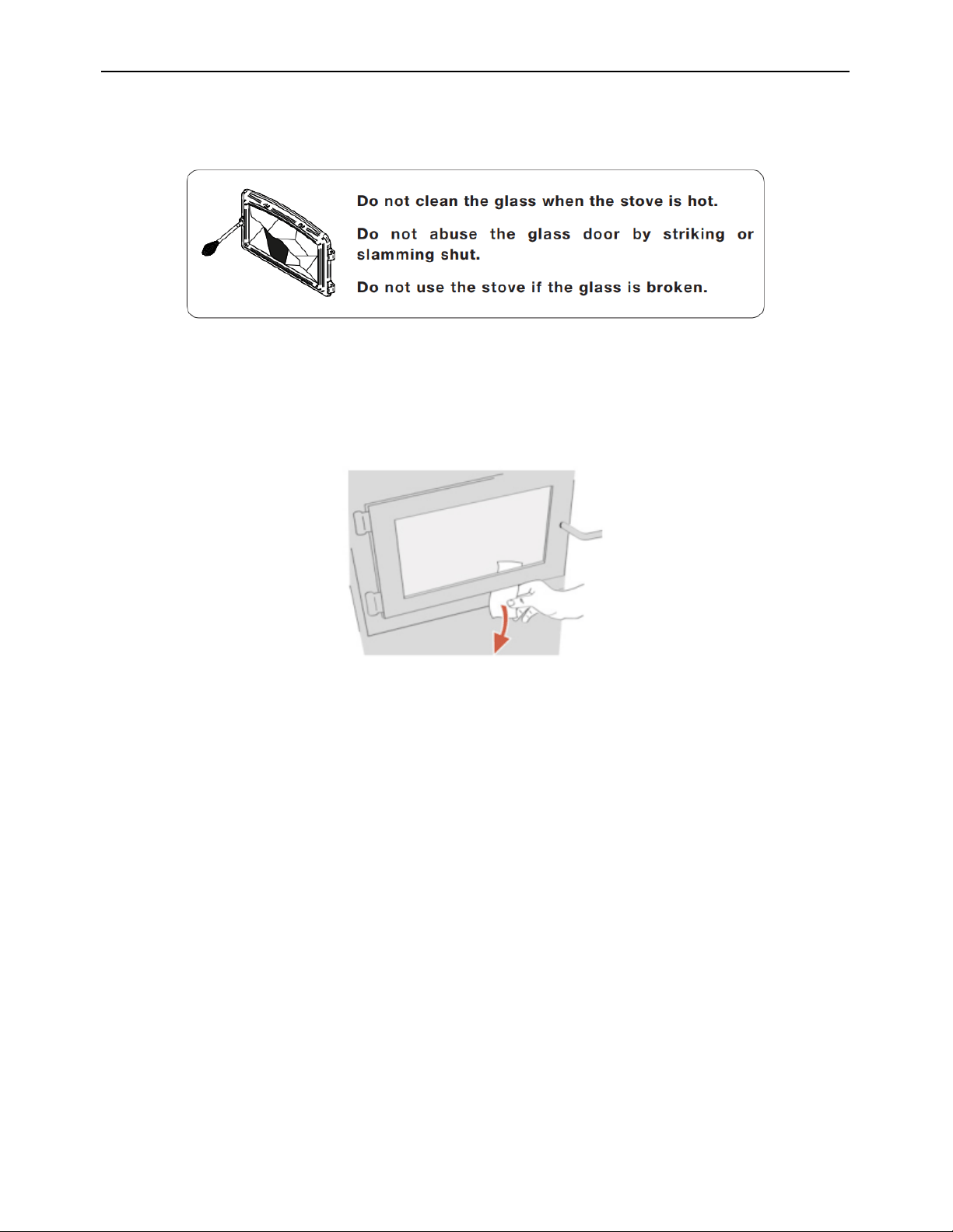
Heat Commander Furnace Installation and Operation Manual
61
section « 10.1.4 Replacement of the glass and gaskets» for installation. Always replace
gaskets with genuine ones. See section « 12 Exploded diagram and parts list ».
10.1.3 Door adjustment
In order to burn at its best efficiency, the furnace door must provide a perfect seal with the
firebox. The tightness of the door seal can be verified by closing and latching the door on a
strip of paper. The test must be performed all around the door. If the paper slips out easily
anywhere, either adjust the door or replace the gasket.
Door adjustment procedure:
1. Unscrew the locking pin (B) and nut (A) from the door.
2. To increase the pressure of the door on the gasket, turn the handle. Counter-clockwise,
to reduce the pressure of the door on the cord, turn the handle clockwise to clockwise.
3. Finally, screw-in the locking pin (B) about 1/4" (6 mm) deep and make sure you lock it
with the nut (A). If after adjustment the door is not tight, replace the door gasket.
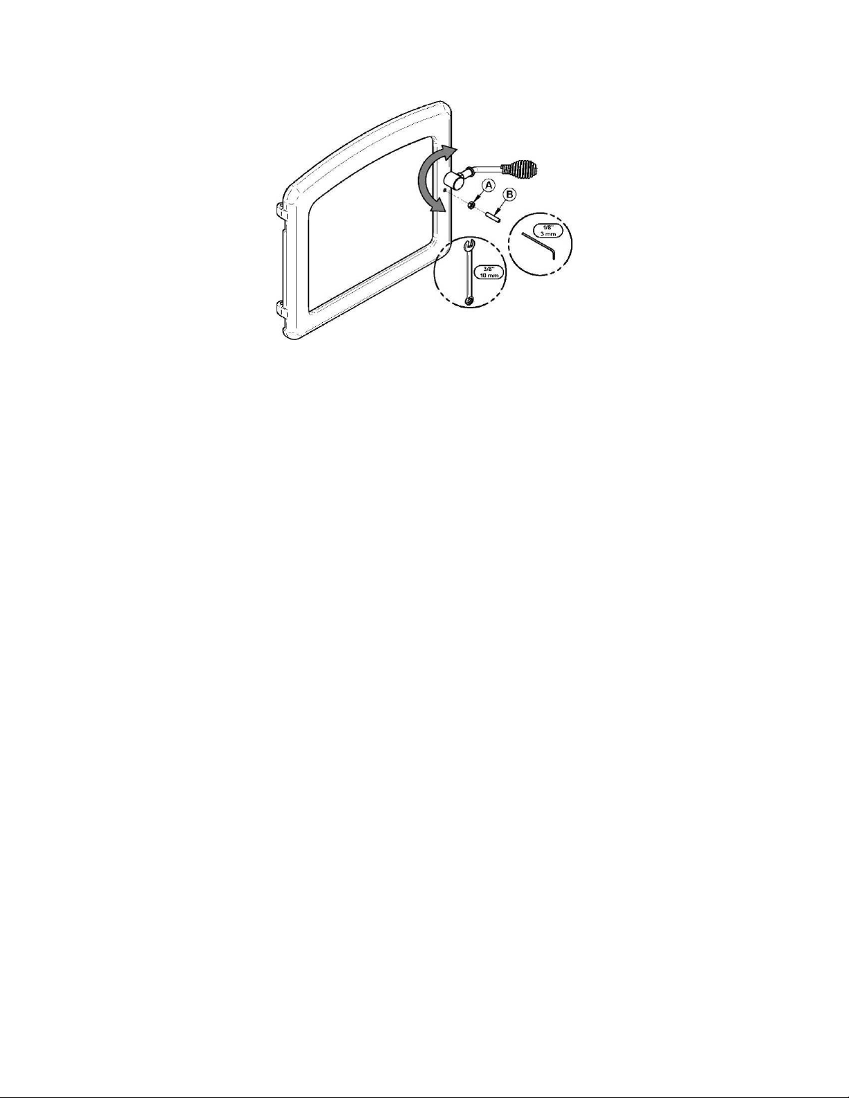
10.1.4 Replacement of the glass and gaskets
After a year or more of use, the gasket of the door will compress and become hard which
can allow air to pass. You can check the air tightness of your door gasket by closing and
locking the door on a piece of paper. Check all around the door. If the paper slides easily
anywhere, adjust the door and the gasket if this is not enough.
Always use a genuine gasket that you can purchase from your dealer. The correct size and
density of the gasket are important to ensure a good seal.
Prior of removing the defective glass, you need to remove the door gasket. Inspect the door
gasket before it is reinstalled to make sure it is in good condition. We suggest replacing the
door and glass gasket at the same time as their level of wear over time is similar.
For the following steps, wearing gloves and safety glasses are recommended for
handling seals can irritate the skin and the glass can be sharp.
- To replace the door gasket, use the steps 1 to 3 and 10 outlined below.
- To replace the glass, use the steps 1 to 6 and 9 to 10 outlined below.
- To replace the glass gasket, use the steps 1 to 10 outlined below.
1. Remove the door (F) and place it on a stable work surface, handle down.
2. Using pliers, remove the door gasket (A).
3. Using a scraper or a small flat screwdriver, remove the adhesive left in the gasket grove
in the door then clean the surface using a commercial vacuum.
4. Use a Phillips screwdriver or a power drill to remove the screws (B) that holds the glass
retainer (C).
5. Remove the glass frame (D).
6. Remove the glass (E) (or pieces of glass if it is damaged) and clean the inside of the
door frame.
7. Remove the old glass gasket.
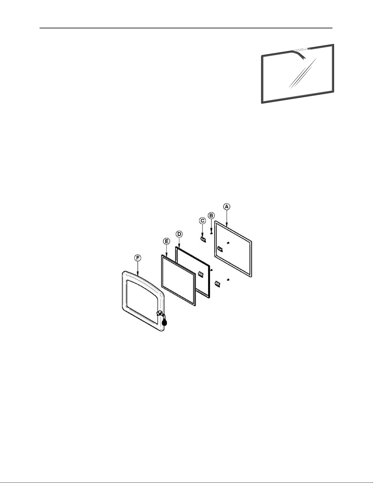
Heat Commander Furnace Installation and Operation Manual
63
8. Install the new gasket on the glass. Remove a part of the paper
covering the gasket adhesive. Center the gasket on the edge
of the glass so that when folded and glued, the gasket is equal
on both sides. Do not stretch the gasket during installation.
Remove a majority of the paper, turn the glass to facilitate and
complete the installation of the gasket. When you return to the
starting point, cut the gasket so that the ends overlap by about
1/2" (13 mm).
9. Install the glass (E) and glass frame (D) centering them in the door frame. Install the
glass retainers (C) taking care not to over tighten the screws (B). Note that the two main
causes of glass breakage are unequal position in the door and screws too tight.
10. Install the new door gasket (A). To do this, use about 1/4" (6 mm) of adhesive to the
bottom of the groove that holds the gasket in the door. Then lay the new gasket starting
from the center of the hinge side and taking care not to stretch the gasket during
installation. Leave about 1/2" (13 mm) of gasket exceed the frame of the door. Once
jointed, push the fibers protruding towards the inside of the groove in the adhesive. Install
the door and let dry for 24 hours before using the furnace.
Do not abuse the glass door by striking or slamming shut. Do not use the furnace if the glass
is broken. To change the glass, perform the same operation described above.
10.1.5 Cleaning and painting the furnace
Do not attempt to clean or paint the furnace when the unit is hot. Painted surfaces can
be wiped down with a damp cloth. Plated or enameled surfaces may be scratched by
abrasive cleaners. To maintain the finish at its original brilliance, use only a damp soft cloth
to clean plated or enameled surfaces.
If the paint becomes scratched or damaged, you can give your wood furnace a brand-new
look by repainting it with heat-resistant or enamel finish paint. Before painting, roughen the
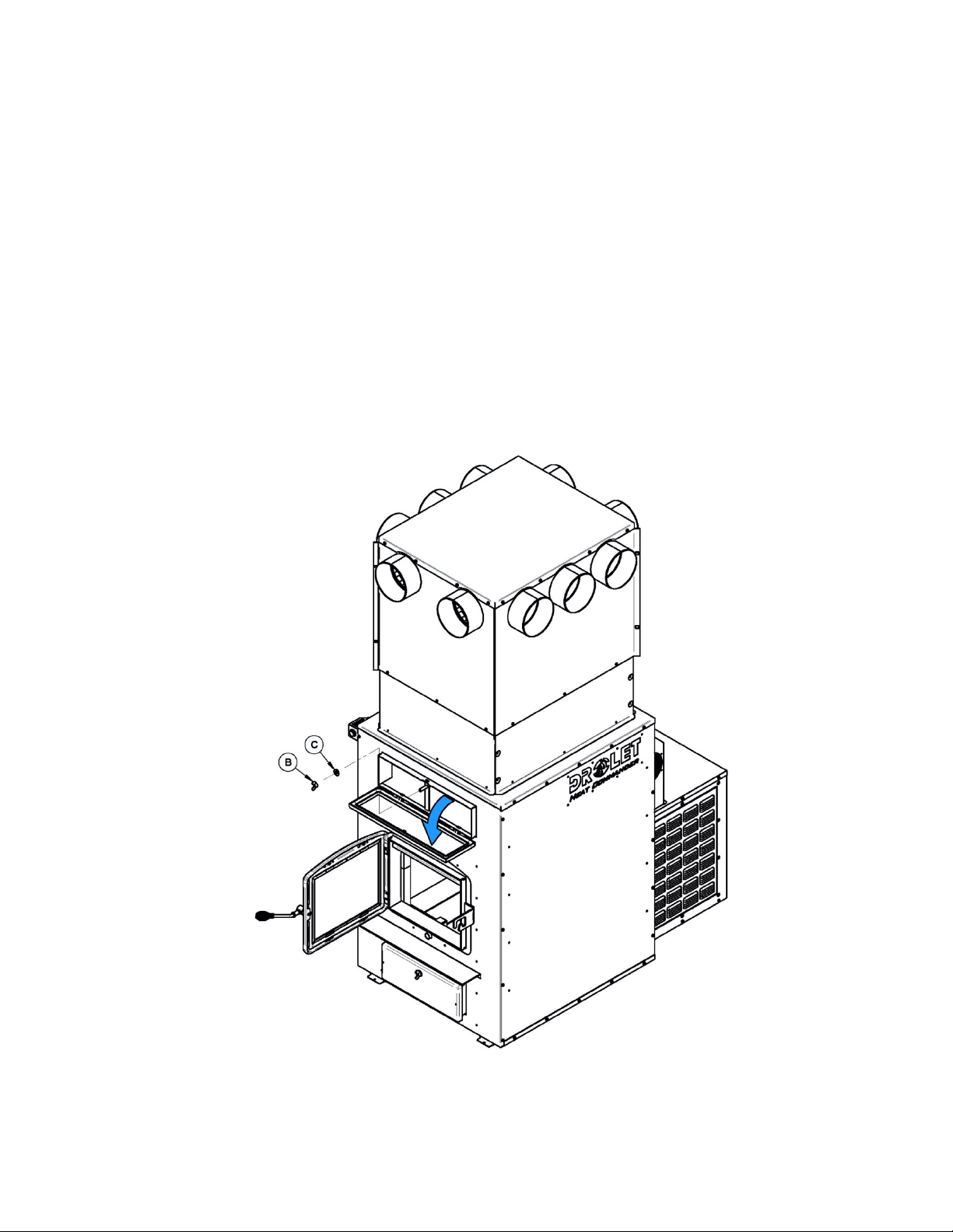
surface with fine sandpaper, wipe it down to remove dust, and apply two thin coats of paint.
For best results, use the same paint that was originally used on the furnace, which is
available in spray cans. See your dealer for details.
10.1.6 Heat exchangers care
Heat exchangers must be cleaned thoroughly at the end of every heating season.
During summer, the air in basements is damper and with minimal air circulation within
the furnace, it can mix with creosote and/or sooth deposits in the exchangers to form
an acid that could accelerate the corrosion process and induce premature decay of
the steel. Corrosion damages are not covered under warranty.
Smoke pipe and exchangers must be inspected regularly during the heating season. Access
to the exchangers is easy and does not require tools.
1. Unscrew the wing nut (B) and remove the washer (C) on the exchanger access door.
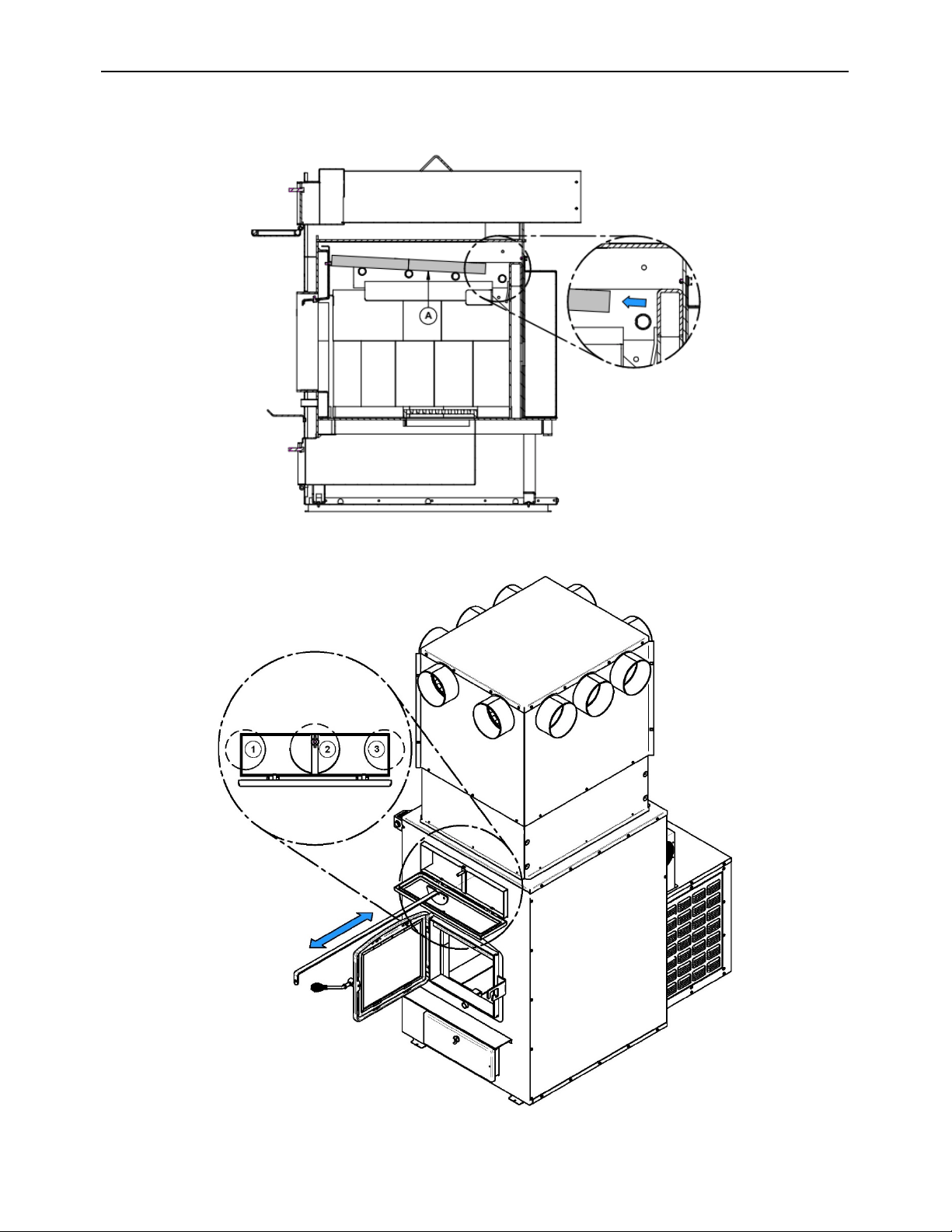
Heat Commander Furnace Installation and Operation Manual
65
2. Move the baffle of the combustion chamber forward.
3. Use the tool provided, clean the three exchanger pipes.
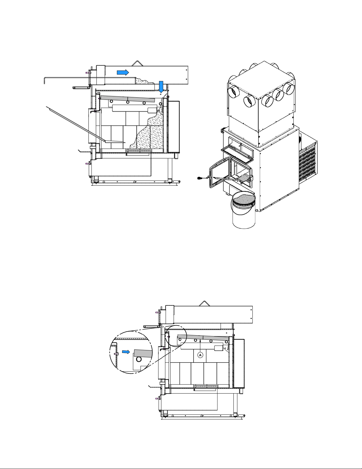
4. Dirt in the lateral exchangers (1 and 3) fall into the combustion chamber at the rear.
5. Dirt in the central exchanger (2) will be removed from the front or the rear of the furnace.
If you remove dirt from the central exchange to the back of the furnace, remove the black
pipe connector to dispose of the deposit.
6. Then, check that the baffle is clear of ash and reposition it in its original position towards
the back of the combustion chamber. Important to note that the furnace will not burn
correctly if the baffle is out of place during use.
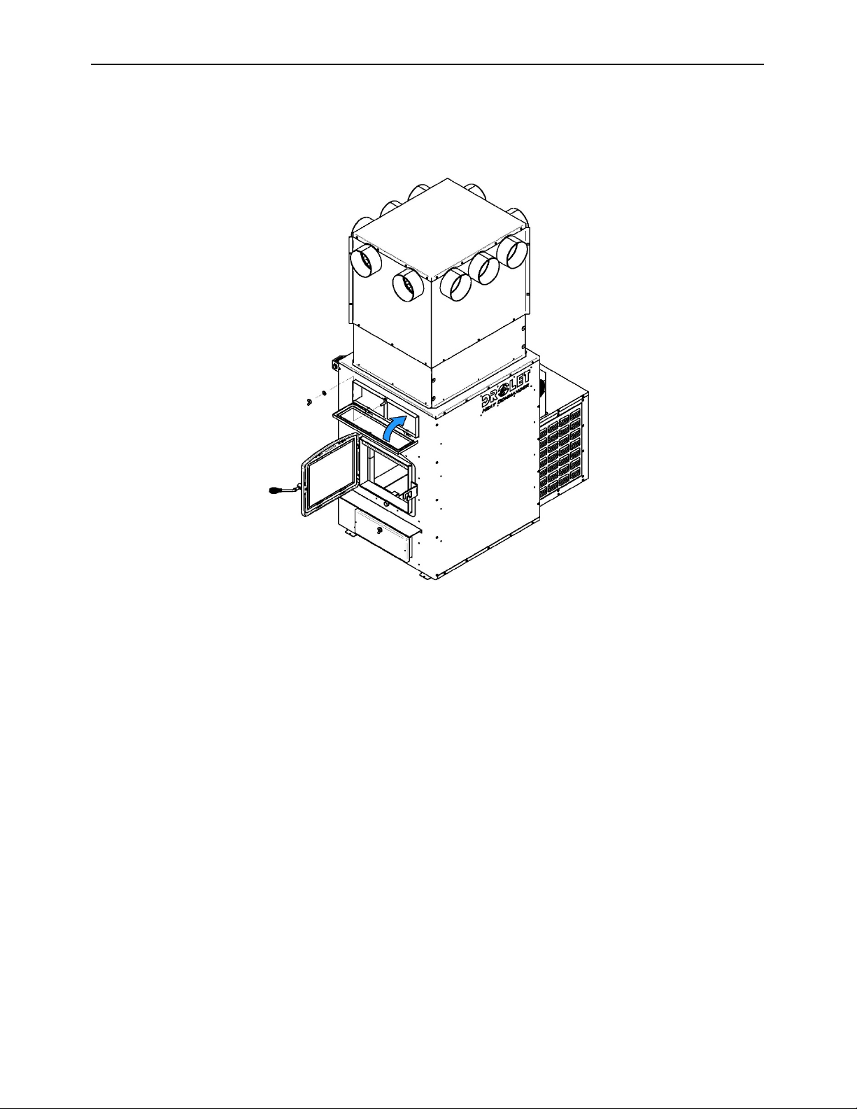
Heat Commander Furnace Installation and Operation Manual
67
7. Close the exchanger access door and secure it using the washer and wing nut.
8. If you have performed from the back part of the furnace, reinstall the black pipe
connector and secure it with three screws.
10.1.7 thermocouples care
1. Move the baffle of the combustion chamber forward.
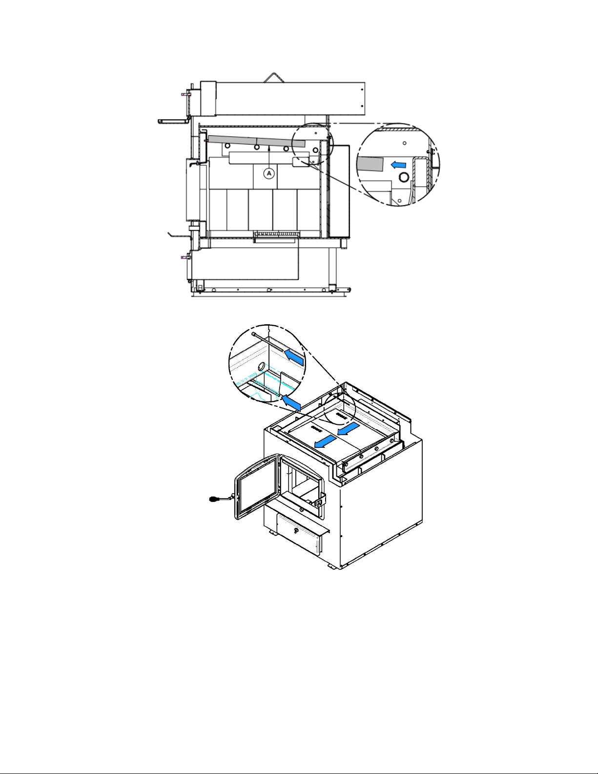
2. With a brush, carefully clean the thermocouples.
3. Then, reposition the baffle in its original position towards the back of the combustion
chamber. Important to note that the furnace will not burn correctly if the
baffle is out of place during use.
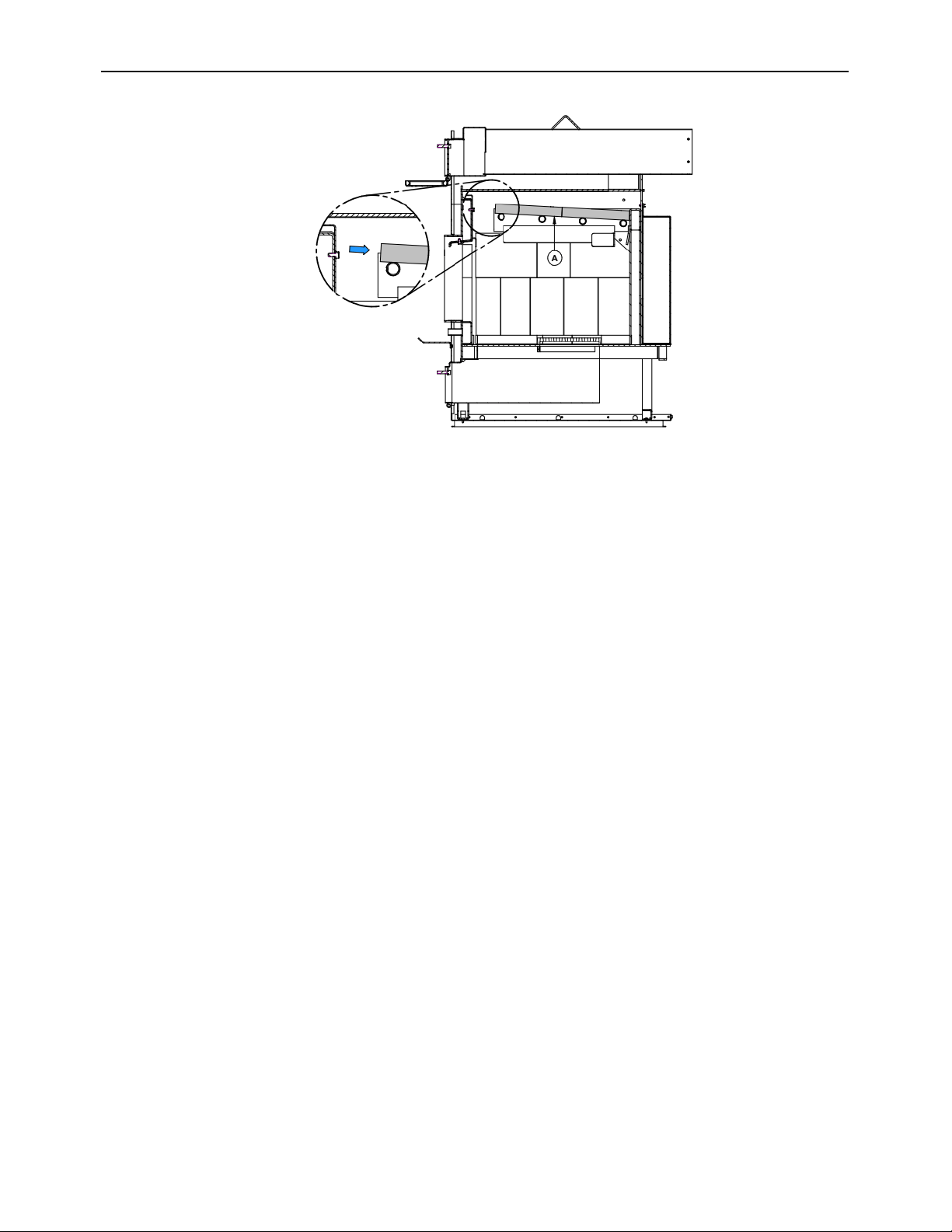
Heat Commander Furnace Installation and Operation Manual
69
10.2 Chimney maintenance
Wood smoke can condense inside the chimney connector and chimney, forming a
combustible deposit called creosote. If creosote is allowed to build up in the venting system,
it can ignite when a hot fire is burned in the furnace and a very hot fire can progress to the
top of the chimney. Severe chimney fires can damage even the best chimneys. Smouldering,
smoky fires can quickly cause a thick layer of creosote to form. Avoid smouldering so the
exhaust from the chimney is mostly clear, creosote builds up more slowly. Your new furnace
has the right characteristics to help you to burn clean fires with little or no smoke, resulting
in less creosote in the chimney.
10.2.1 Cleaning Frequency
It is not possible to predict how much or how quickly creosote will form in your chimney. It is
important, therefore, to check the build-up in the chimney monthly until you determine the
rate of creosote formation. Even if creosote forms slowly in your system, the chimney should
be cleaned and inspected at least once each year.
Contact your local municipal or provincial fire authority for information on how to handle a
chimney fire. Have a clearly understood plan to handle a chimney fire.
10.2.2 Cleaning the chimney
Chimney sweeping can be a difficult and dangerous job. People with no chimney sweeping
experience will often prefer to hire a professional chimney sweep to inspect and clean the
system for the first time. After seeing the cleaning process, some will choose to do it
themselves.
The most common equipment used are fiberglass rods with threaded fittings and stiff plastic
brushes. The brush is forced up and down inside the chimney flue to scrub off the creosote.

CAUTION: Operation of your furnace without the baffle may cause unsafe and hazardous
temperature conditions and will void the warranty.
10.3 Firebricks inspection
Check firebricks to ensure that none are broken or damaged in any way. If so, have the
damaged ones replaced.
10.4 Smoke pipe inspection
• The smoke pipe must be inspected regularly during the heating season.
• The pipe must be examined carefully to detect any defect or damage.
• The pipe can be reassembled if no defect is detected and defective pipe must be
replaced immediately.
• INSPECT FLUE PIPES, FLUE PIPE JOINTS, AND FLUE PIPE SEALS REGULARLY
TO ENSURE THAT SMOKE AND FLUE GASES ARE NOT DRAWN INTO, AND
CIRCULATED BY, THE AIR-CIRCULATION SYSTEM.
10.5 Blower motor maintenance
Periodic cleaning of the blower housing, impeller and louver as well as blower and blower
blades using a vacuum cleaner is necessary in order not to affect performance and cause
overheating of the system.

Heat Commander Furnace Installation and Operation Manual
71
11 Troubleshooting
PROBLEM
CAUSES
SOLUTIONS
Heating inefficient during the
first combustions. Lack of
draft.
If installed, improper
adjustment of the barometric
damper (opened too wide).
Chimney flue restriction (too
long. 90
o
elbows).
Adjust the damper, minimize
the smoke pipe length and use
of 45
o
elbows.
Furnace burns well, warm air
plenum is very hot but there is
not much heat coming out in
the room.
Improper installation of the
ducts, low static pressure,
unbalanced system (too many
warm air outlets and not
enough fresh air return).
Rearrange the ducting to
respect the minimum static
pressure of 0.20 in. W.C. (50
Pa) in the plenum.
Furnace consumes a lot of
wood.
The thermostat always calls for
heat or is too close to a source
of cold air. Air controls not
properly adjusted. House not
insulated enough. Furnace
and ash drawer door not
airtight. Furnace too small for
the surface to be heated.
Unbalanced ventilation
system.
Relocate the thermostat.
Rebalance the ventilation
system to increase the air flow
in the room where the
thermostat is located. Check
tightness of air controls,
furnace and ash drawer door.
A lot of creosote, moderate
heat output.
Wet wood, lack of draft.
Barometric damper not
properly adjusted. Restriction
in the furnace or chimney.
Use dry wood. Adjust the
barometric damper. Clean the
chimney, flue pipe and the
furnace exchangers.
Furnace heats a lot but the
warm air duct does not get hot.
No static pressure.
Unbalanced ventilation
system. Wet wood or low
grade wood.
Use dry wood. Rearrange the
ventilation system correctly.
Reload button LED blinking
fast
Unit is overheating
Leave the door closed, do not
add more wood and wait for
the end of combustion. Check
the door and the ash drawer
door for leaks. Excessive
chimney draft. Check the
tightness of the air controls.
Primary air controls never
opens.
Furnace is not plugged-in.or
an electrical component is
faulty.
Make sure the furnace is
plugged-in a functional power
outlet. Test and replace if
necessary, control switch,
thermostat, and air control
motor.
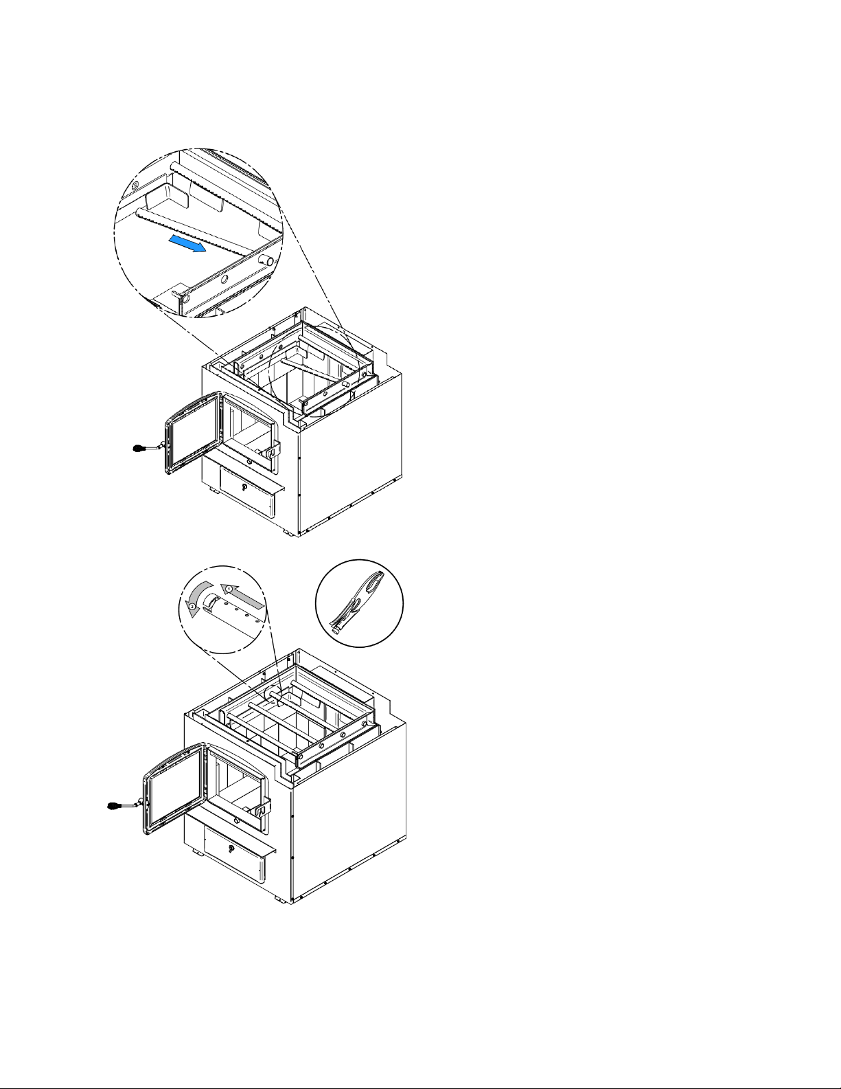
11.1 Installation of secondary air tubes and baffle
Note that secondary air tubes can be replaced without removing the baffle board. Moreover,
the 4 tubes are identical so there is no need to worry about the position of each tube.
1- Starting with the rear tube, lean and
insert the right end of the secondary air
tube into the rear right channel hole.
Then lift and insert the left end of the
tube into the rear left channel.
2- Align the notch in the left end of the tube
with the key of the left air channel hole.
Using a “Wise grip” hold the tube and
lock it in place by turning the tube as
shown. Make sure the notch reaches
the end of the keyway.
3- Repeat step 1 and 2 for the other
secondary air tubes.
4- To remove the tubes, use the above
steps in reverse order.
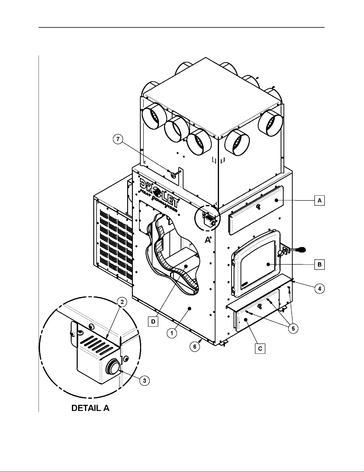
Heat Commander Furnace Installation and Operation Manual
73
12 Exploded diagram and parts list
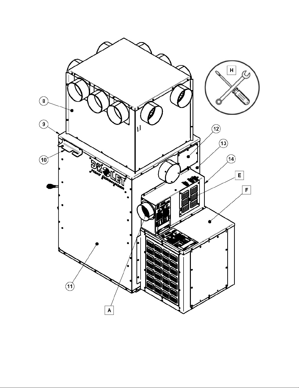
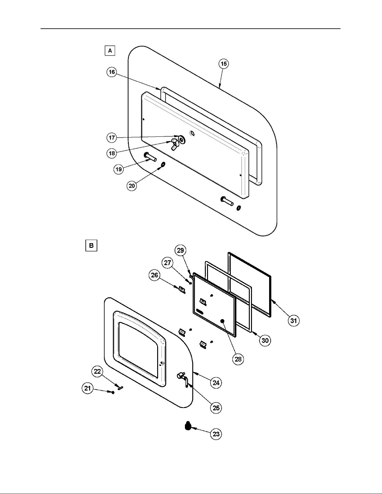
Heat Commander Furnace Installation and Operation Manual
75
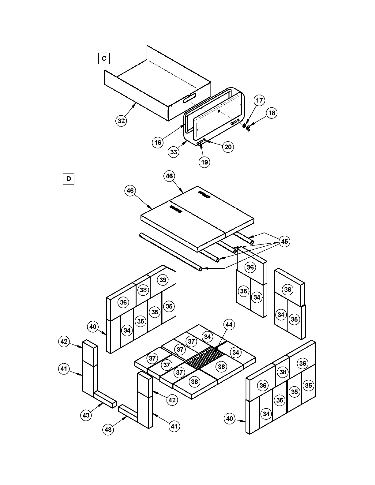
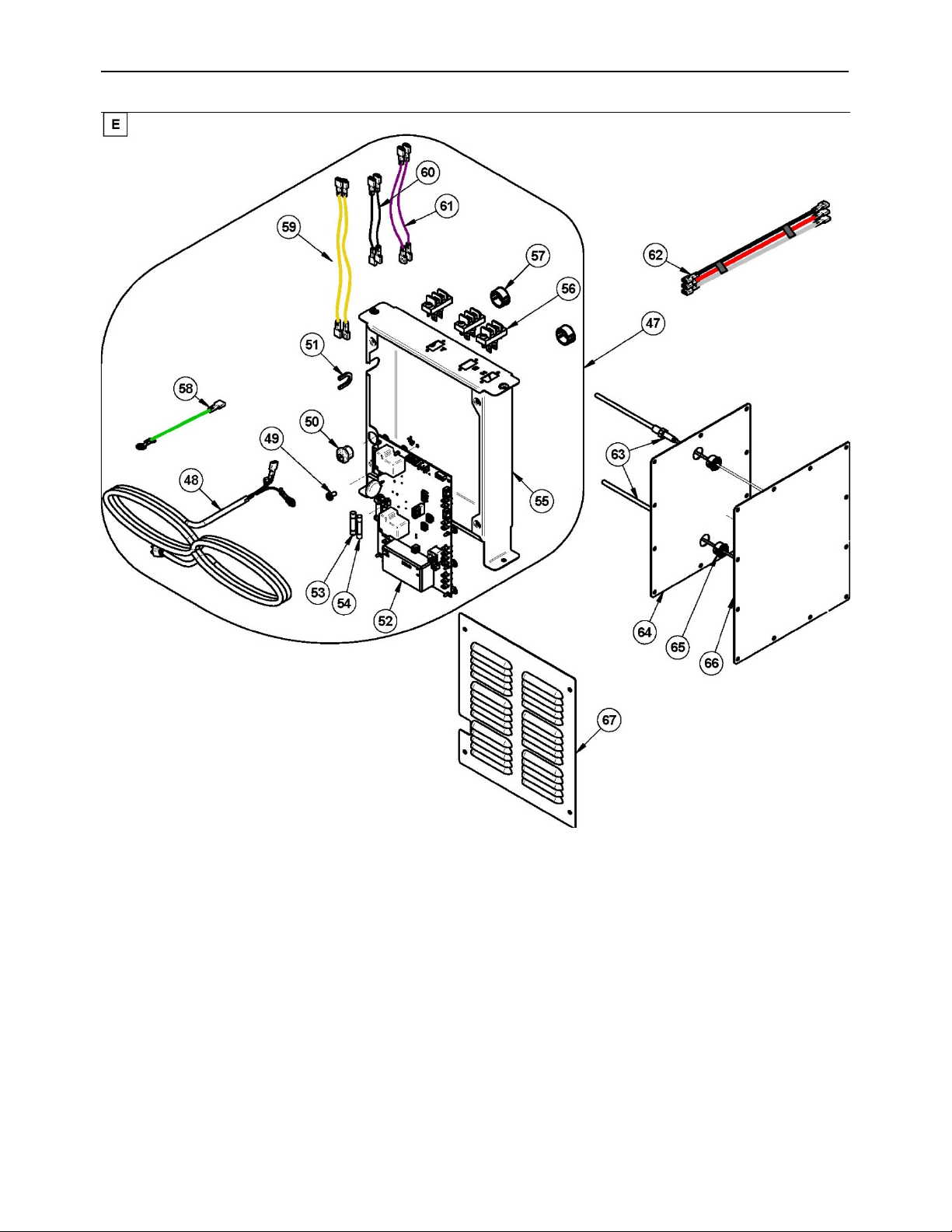
Heat Commander Furnace Installation and Operation Manual
77
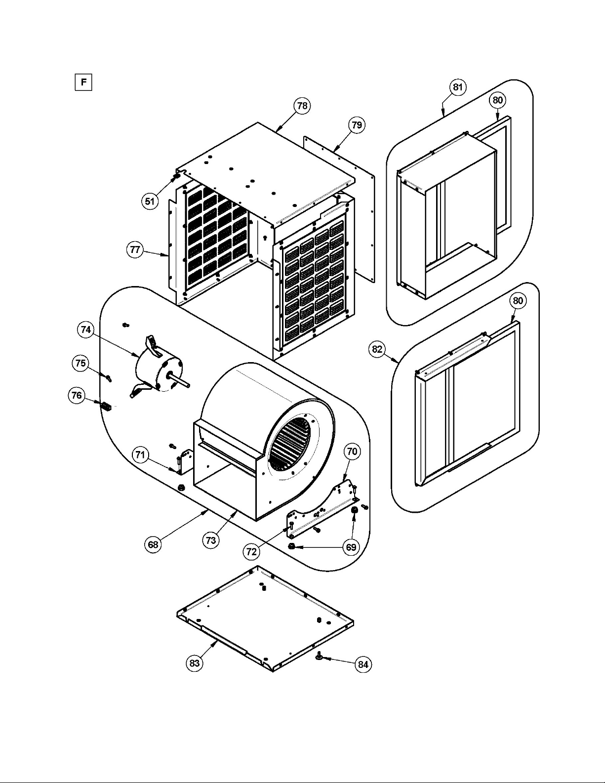
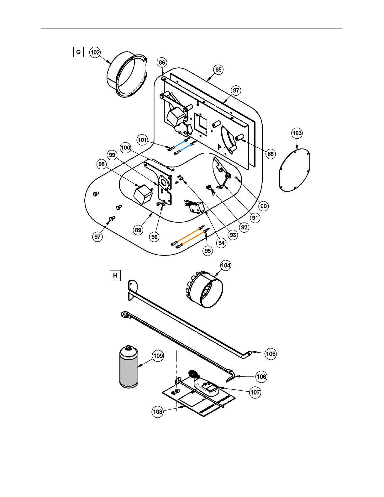
Heat Commander Furnace Installation and Operation Manual
79

IMPORTANT: THIS IS DATED INFORMATION. When requesting service or replacement
parts for your furnace, please provide the model and the serial number. We reserve the right
to change parts due to technology upgrade or availability. Contact an authorized dealer to
obtain any of these parts. Never use substitute materials. Use of non-approved parts can
result in poor performance and safety hazards.
#
ITEM
DESCRIPTION
QTÉ
1
SE66170
LEFT PANEL ASSEMBLY
1
2
PL66189
SWITCH BRACKET
1
3
44241
SWITCH PUSH SPST-NO 10A 14V
1
4
PL56276
ASH SHELF
1
5
30154
BLACK SCREW #10 X 5/8" QUADREX #2 TYPE A
3
6
SE66160
AIR JACKET FLOOR ASSEMBLY
1
7
44096
100 OHM RTD PROBE 38" WIRE
1
8
SE66201
PLENUM ASSEMBLY
1
9
PL66172
FURNACE TOP
1
10
PL66196
TOOL HOLDER
1
11
SE66168
RIGHT PANEL ASSEMBLY
1
12
PL66211
THERMOCOUPLE ACCESS PANEL
1
13
PL66164
FURNACE'S BACK
1
14
PL66188
AIR INTAKE
1
15
SE66176
HEAT EXCHANGER ACCESS DOOR
1
16
AC06900
BLACK 1/2'' ROUND X 9' GASKET KIT WITH ADHESIVE
1
17
30210
WASHER 29/32" OD X 3/8" ID ZINC
2
18
30416
WING NUT 3/8"-16
2
19
30168
HINGE PIN 5/16"Ø X 1 1/4"L
4
20
30055
HINGE PIN RETAINING RING 5/16" ID X 0.512" OD
4
21
30100
BLACK HEX NUT 1/4 - 20
1
22
30128
SOCKET SET SCREW 1/4"-20 X 1 1/4"
1
23
AC07869
3/8" BLACK COIL HANDLE
1
24
SE24258
CAST IRON DOOR WITH HANDLE
1
25
AC09151
REPLACEMENT HANDLE KIT
1
26
PL51351
GLASS RETAINER FRAME BRACKET
4
27
30124
SCREW #8 - 32 X 5/16'' TRUSS QUADREX ZINC
4
28
SE66213
GLASS WITH GASKET - 13 1/8"W X 10 7/8"H
1
29
AC06400
3/4" (FLAT) X 6' BLACK SELF-ADHESIVE GLASS GASKET
1
30
AC06725
GLUE AND 3/4" X 7' WHITE DOOR GASKET KIT
1
31
PL51349
GLASS RETAINER FRAME
2
32
PL66175
ASH PAN
1
33
SE48054
HEAT EXCHANGER ACCESS DOOR
1
34
29015
4'' X 9'' X 1 1/4'' REFRACTORY BRICK
6
35
29010
4 1/2" X 9" X 1 1/4" REFRACTORY BRICK
8

Heat Commander Furnace Installation and Operation Manual
81
#
ITEM
DESCRIPTION
QTÉ
36
29005
6" X 8 1/4" X 1 1/4'' REFRACTORY BRICK HD
7
37
29000
4'' X 8'' X 1 1/4'' REFRACTORY BRICK
5
38
PL66190
HD 4 1/2'' X 6'' X 1 1/4'' REFRACTORY BRICK
2
39
PL66192
6'' X 8 1/4'' X 1 1/4'' HD REFRACTORY BRICK
1
40
29007
3 1/4'' X 9'' X 1 1/4'' REFRACTORY BRICK
2
41
PL36266
REFRACTORY BRICK 3 1/2" X 8 1/2" X 1 1/4"
2
42
PL36116
3 1/2" X 5 1/8'' X 1 1/4'' REFRACTORY BRICK
2
43
PL66191
1 1/4'' X 6'' X 1 1/4'' HD REFRACTORY BRICK
2
44
24089
CAST IRON ASH GRATE 4 1/2" X 9"
1
45
PL66163
SECONDARY AIR TUBE
4
46
21618
C-CAST FIREWALL - 9.062" X 13.031" X 1.250"
2
47
SE66186
CONTROL BOARD ASSEMBLY
1
48
60013
POWER CORD 96" X 18-3 type SJT (50 pcs per carton)
1
49
31063
SCREW 10-24 X 3/8 HWS TY 23 GREEN
1
50
60008
BLACK NYLON BUSHING
1
51
30494
PANDUIT POLYETHYLENE EXTRUSION
0.1
52
PL66213
CONTROL BOARD HEAT COMMANDER
1
53
44136
FUSE 12A / 250V ¼’’ Ø X 1 ¼’’L
1
54
44137
FUSE 1A / 250V ¼’’ Ø X 1 ¼’’L
1
55
PL66186
CIRCUIT BOARD HOLDER
1
56
60036
THERMOSTAT TERMINAL
3
57
30412
UNIVERSAL SNAP-IN BUSHING BLACK
2
58
60340
GREEN ELECTRICAL WIRE TEW 105 DEG C 18 AWG 4 1/16''
1
59
60335
18 AWG CSA TEW 105 DEG C 600V WIRE 9 1/2''
2
60
60429
BLACK ELECTRICAL WIRE TEW 105 DEG C 18 AWG 5 1/2"
2
61
60430
PURPLE ELECTRICAL WIRETEW 105 DEG C 18 AWG 7 1/2"
2
62
60427
BUTTON WIRING HARNESS
1
63
60413
TYPE K UNGROUNDED THERMOCOUPLE
2
64
PL66173
INNER ACCES PANEL
1
65
30413
SNAP-IN BUSHING BLACK
2
66
PL66174
JACKET ACCES PANEL
1
67
PL66209
CONTROL BOARD ACCESS PANEL
1
68
SE48245
G10 BLOWER ASSEMBLY WITH 1/3HP MOTOR (115v 5A 575W)
1
69
30335
BLOWER ANTI-VIBRATION CUSHION
4
70
30336
RIGHT HOUSING SUPPORT FOR G10 BLOWER
1
71
30334
LEFT HOUSING SUPPORT FOR G10 BLOWER 10-458-085
1
72
30109
BOLT HEX 1/4 - 20 X 1"
4
73
51011
BLOWER HOUSING G-10 DD
1
74
51003
1/3 HP 4 SPEED MOTOR FOR G-10 DD
1
75
30094
HEX SCREW WASHER HEAD 1/4-20 X 3/4" F ZINC TYPE
7

#
ITEM
DESCRIPTION
QTÉ
76
44186
5 POSITIONS TERMINAL BLOCK
1
77
PL66179
BLOWER BOX CONTOUR
1
78
PL66180
BLOWER BOX TOP
1
79
PL66044
BLOWER BOX CAP
2
80
21044
FURNACE CARDBOARD AIR FILTER 20" X 15" X 1"
2
81
AC01392
RETURN AIR DUCT WITH FILTER
1
82
AC01390
CARDBOARD FRAME AIR FILTER WITH SUPPORT (20" X 15" X 1")
1
83
PL66178
BLOWER BOX BASE
1
84
30536
LEVELING BOLT 1/4 - 20 X 1''
2
85
SE66193
DAMPER ASSEMBLY
1
86
PL66193
DAMPER MOTOR BRACKECT
1
87
21621
AIR ENTRY HATCH GASKET
1
88
31222
HATCH SPACER
6
89
SE66194
COMPLETE DAMPER ASSEMBLY
1
90
30117
SOCKET SET SCREW #10-32 X 1/4"
2
91
SE66195
DAMPER
2
92
31221
HATCH SPRING
2
93
30354
THREAD SCREW 8-32 X 5/16'' TYPE F TRUSS QUADREX STEEL C1022
ZINC
2
94
44190
LIMIT SWITCH
2
95
60431
ORANGE ELECTRICAL ASSEMBLY TEW 105 DEG C 18 AWG 19"
2
96
30154
BLACK SCREW #10 X 5/8" QUADREX #2 TYPE A
4
97
30084
NUT 1/4-20 X 1/2" GRADE 5
6
98
44235
HYBRID STEPPING MOTOR - 12V; 1.8 DEG STEP; 4.8 KG/CM
2
99
PL66194
DAMPER BRACKET
2
100
31212
SCREW M3 X 8 ROUND HEAD SIX PAN HOLLOW TYPE C BLACK
8
101
60428
BLUE ELCTRICAL WIRE TEW 105 DEG C 18 AWG 22''
2
102
SE66198
FRESH AIR INTAKE ADAPTER
1
103
PL66200
AIR INTAKE COVER
1
104
PL66220
6'' ADAPTER
10
105
PL48170
HEAT EXCHANGER SCRAPER
1
106
PL48173
POKER
1
107
44171
MOISTURE READER
1
108
46201
DF02003 INSTRUCTION MANUAL
1
109
AC05959
METALLIC BLACK STOVE PAINT - 342 g (12oz) AEROSOL
1
Heat Commander Furnace Installation and Operation Manual
83
PART C – FEATURES AND SAFETY
13 General information
13.1 Appliance performance
(1)
Fuel type
Dry cordwood
Recommended heating area
[*]
1,000 to 2,500 ft² (93 à 232 m²)
Firebox volume
3.6 ft³ (0.102 m³)
Maximum burn time
[*]
10 h
Maximum input capacity (dry cordwood)
(2)
310,000 BTU
Overall heat output rate (min. to max.)
(3)
19,354 BTU/h to 47,052 BTU/h (5.6 kW to 13.8 kW)
Nominal heat output at 15lb/ft³ fuel loading density
75,000 BTU/h
Average overall efficiency
(4)
76.6 % (HHV)
(5)
Delivered heat output rate (min. to max.)
(7)
13,297 BTU/h to 42,234 BTU/h (3.9 kW to 12.4 kW)
Average delivered efficiency
(8)
60.7 % (HHV)
(5)
Optimum efficiency
(9)
83.2% LHV at minimum burn rate
Average particulate emissions rate
(10)(11)
0.095 lb/mmBTU (0.041 g/MJ)
Average CO
(12)
8.78 lb/mmBTU (3.78 g/MJ)
Average electrical power consumption
(13)
330 W
[*]
Recommended heating area and maximum burn time may vary subject to location in home, chimney draft,
heat loss factors, climate, fuel type and other variables. The recommended heating area for a given
appliance is defined by the manufacturer as its capacity to maintain a minimum acceptable temperature
considering that the space configuration and the presence of heat distribution systems have a significant
impact in making heat circulation optimum.
(1)
Values are as measured per CSA B415.1-10, except for the recommended heating area, firebox volume,
maximum burn time and maximum input capacity. Performances based on a fuel load prescribed by the
standard at 10 lb/ft³ and with a moisture content between 18% and 28%.
(2)
Input value at 10lb/ft³ fuel loading density and dry energy value of 8,600BTU/lb.
(3)
Overall: Radiated and delivered heat together at10lb/ft³ fuel loading density over one total burn cycle.
(4)
Efficiency based on delivered heat when allowing cycling from high to low burn to simulate thermostat demand.
(5)
Higher Heating Value of the fuel.
(6)
Lower Heating Value of the fuel.
(7)
Delivered: Remotely provided to other rooms through ducting at 10 lb/ft³ fuel loading density over one total
burn cycle.
(8)
Efficiency based on radiated and delivered heat when allowing cycling from high to low burn to simulate
thermostat demand.
(9)
Optimum overall efficiency at a specific burn rate (LHV).
(10)
Based on delivered heat output.
(11)
This appliance is officially tested and certified by an independent agency.
(12)
Carbon Monoxide. Based on overall heat output at 10lb/ft³ fuel loading density.
(13)
Unless stated otherwise, measures were taken directly at the main power source and include all electrical
components present in the appliance.

13.2 General Features
Maximum log length
21" (533 mm) north-south**
Diameter of the flue collar
6 in. (152 mm)
Recommended connector pipe diameter
6 in. (152 mm)
Recommended chimney diameter
6 in. (152 mm)
Required type of chimney
CAN/ULC S629, UL 103 HT (2100 °F)
Baffle material
C-Cast
Alcove installation
Not approved
Mobile home installation
‡
Not approved
Appliance weight (without option)
605 lb (275 kg)
Shipping weight (without option)
740 lb (337 kg)
Blower
Included
Filter
Non-included: 15 in x 20 in x 1 in
Particulate emission standard
EPA / CSA B415.1-10
USA standard (safety)
UL 391
Canadian standard (safety)
CAN/CSA B366.1
** East-west: through the door you see the longitudinal sides of the logs; north-south: through the door you
see the tips of the logs.
‡
Mobile home (Canada) or manufactured home (USA): The US department of Housing and Urban
Development describes “manufactured homes” better known as “mobile homes” as followed; buildings built on
fixed wheels and those transported on temporary wheels/axles and set on a permanent foundation. In Canada,
a mobile home is a dwelling for which the manufacture and assembly of each component is completed or
substantially completed prior to being moved to a site for installation on a foundation and connection to service
facilities and which conforms to the CAN/CSA-Z240 MH standard.
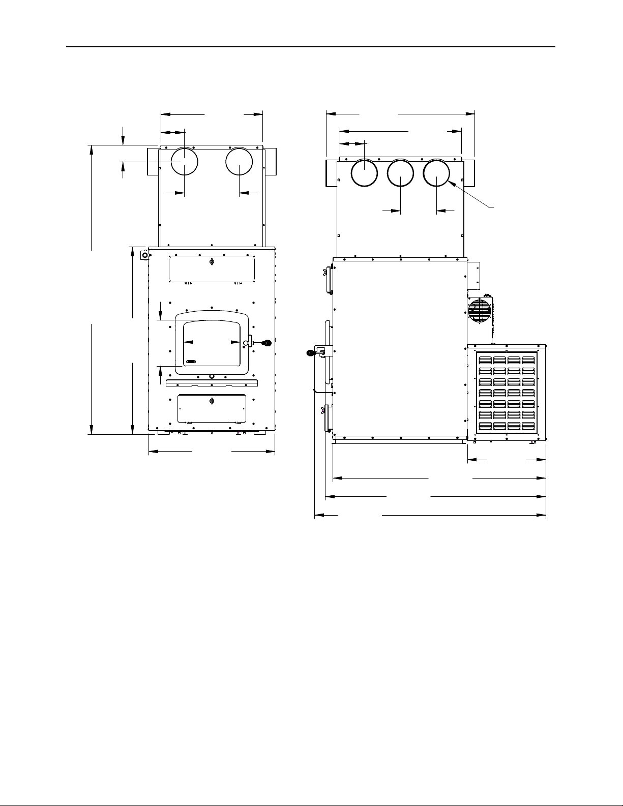
Heat Commander Furnace Installation and Operation Manual
85
13.2.1 Technical data
12"
305mm
C/C
5 1/4"
132mm
22 3/8"
569mm
3 5/8"
92mm
TYP.
63 1/2"
1612mm
MIN
88'' MAX.
2235mm
41 1/8"
1045mm
10 1/8"
256mm
12 3/8"
315mm
27 3/4"
705mm
17 3/8"
440mm
47 1/8"
1197mm
48 3/4"
1239mm
51 1/8"
1299mm
8"
202mm
C/C
O
6"
150mm
TYP.
5 1/2"
139mm
26 7/8"
684mm
32 7/8"
836mm
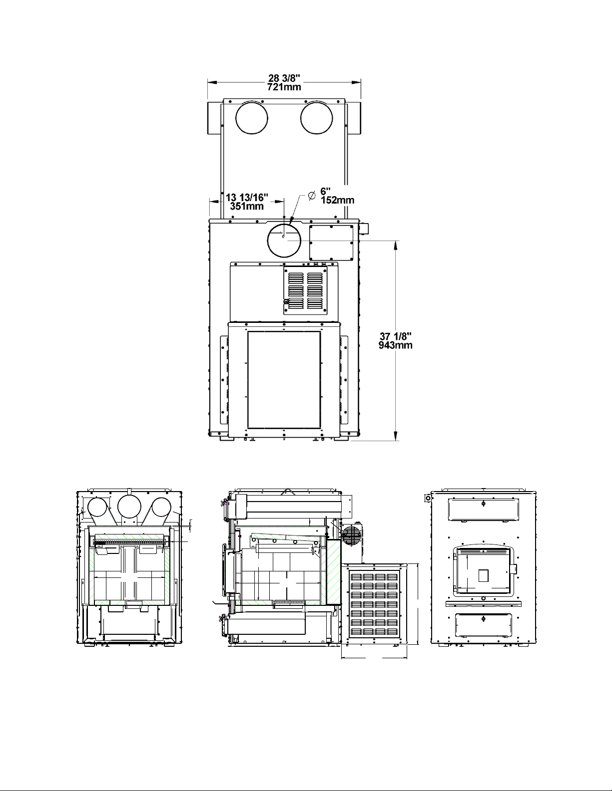
18 3/4"
476mm
1/4"
6mm
3/16"
5mm
16 1/8"
411mm
22 3/4"
578mm
10"
254mm
13 3/4"
348mm
17 3/8"
440mm
21 3/8"
544mm

Heat Commander Furnace Installation and Operation Manual
87
13.3 The benefits of low emissions and high efficiency
The low smoke emissions produced by the special features inside the furnace firebox mean
that your household will release up to 90 percent less smoke into the outside environment
than if you used an older conventional wood furnace. But there is more to the emission
control technologies than protecting the environment.
The smoke released from wood when it is heated contains about half of the energy content
of the fuel. By burning the wood completely, your furnace releases all the heat energy from
the wood instead of wasting it as smoke up the chimney. Also, the features inside the firebox
allow you to reduce the air supply to control heat output, while maintaining clean and efficient
flaming combustion, which boosts the efficient delivery of heat to your home.
The emission control and advanced combustion features of your furnace can only work
properly if your fuel is in the correct moisture content range of 15 to 20 percent. See
PART 2 –OPERATION, MAINTENANCE AND TROUBLESHOOTING for suggestions on
preparing fuel wood and judging its moisture.
13.4 The SBI commitment to you and the environment
The SBI team is committed to protecting the environment, so we do everything we can to
use only materials in our products that will have no lasting negative impact on the
environment.
13.4.1 What is your new furnace made of?
The body of your furnace, which is most of its weight, is carbon steel. Should it ever become
necessary many years in the future, almost the entire furnace can be recycled into new
products, thus eliminating the need to mine new materials.
The paint coat on your furnace is very thin. Its VOC content (Volatile Organic Components)
is very low. VOCs can be responsible for smog, so all the paint used during the
manufacturing process meets the latest air quality requirements with regards to VOC
reduction or elimination.
The air tubes are stainless steel, which can also be recycled.
The C-Cast baffle is made of an aluminosilicate fibre material that is compressed with a
binder to form a rigid board. C-Cast can withstand temperatures above 2,000 °F. It is not
considered hazardous waste. Disposal at a landfill is recommended.
Lightweight firebrick is made of pumice and cement. Pumice is in fact volcanic rock, a
naturally green product found in the Northwest United States. Disposal at a landfill is
recommended.
The door and glass gaskets are fibreglass which is spun from melted sand. Black gaskets
have been dipped into a solvent-free solution. Disposal at a landfill is recommended.
The door glass is a 4 mm thick ceramic material that contains no toxic chemicals. It is
basically made of raw earth materials such as sand and quartz that are combined in such a
way to form a glass at high temperatures. Ceramic glass will not re-melt in the same way as
normal glass, so it should not be recycled with your regular household products. Disposal at
a landfill is recommended.

14 Safety information
14.1 Cautions and warnings
• A CARBON MONOXIDE (CO) DETECTOR/ALARM IS REQUIRED IN THE ROOM IN WHICH THE FURNACE IS
INSTALLED.
• HOT WHILE IN OPERATION, KEEP CHILDREN, CLOTHING AND FURNITURE AWAY. CONTACT MAY CAUSE
SKIN BURNS. GLOVES MAY BE NEEDED FOR FURNACE OPERATION.
• USING A FURNACE WITH CRACKED OR BROKEN COMPONENTS, SUCH AS GLASS OR FIREBRICKS OR
BAFFLES MAY PRODUCE AN UNSAFE CONDITION AND MAY DAMAGE THE FURNACE.
• OPERATE ONLY WITH DOOR FULLY CLOSED. IF DOOR IS LEFT PARTLY OPEN, GAS AND FLAME MAY BE
DRAWN OUT OF THE OPENING, CREATING RISKS FROM BOTH FIRE AND SMOKE.
• WARNING: AN EXCESSIVE DRAFT MAY CAUSE OVERHEATING AND MAKE THE CONTROL OF THE FIRE
DIFFICULT.
• THIS FURNACE IS NOT DESIGNED TO BE USED WITH THE DOOR OPEN. THE DOOR MAY BE OPEN ONLY
DURING LIGHTING PROCEDURES OR RELOADING. DO NOT LEAVE THE FURNACE UNATTENDED WHEN
THE DOOR IS SLIGHTLY OPENED DURING IGNITION. ALWAYS CLOSE THE DOOR AFTER IGNITION.
• NEVER USE GASOLINE, GASOLINE-TYPE LANTERN FUEL (NAPHTHA), FUEL OIL, MOTOR OIL, KEROSENE,
CHARCOAL LIGHTER FLUID, OR SIMILAR LIQUIDS OR AEROSOLS TO START OR ‘FRESHEN UP’ A FIRE IN
THIS FURNACE. KEEP ALL SUCH LIQUIDS OR AEROSOLS WELL AWAY FROM THE FURNACE WHILE IT IS
IN USE.
• DO NOT STORE FUEL WITHIN HEATER MINIMUM INSTALLATION CLEARANCES.
• BURN ONLY SEASONED NATURAL FIREWOOD.
• DO NOT BURN:
o GARBAGE OF ANY KIND,
o COAL OR CHARCOAL,
o TREATED, PAINTED OR COATED WOOD,
o PLYWOOD OR PARTICLE BOARD,
o FINE PAPER, COLORED PAPER OR CARDBOARD,
o ALL MANUFACTURED LOGS,
o SALTWATER DRIFTWOOD OR
o RAILROAD TIES.
• DO NOT USE LIQUIDS SUCH AS KEROSCENE OR DIESEL FUEL TO START A FIRE.
• DO NOT ELEVATE THE FIRE BY USING A GRATE IN THIS FURNACE.
• DO NOT INSTALL AN AUTOMATIC FEEDER ON THIS FURNACE.
• DO NOT INSTALL A MANUAL DAMPER ON THIS FURNACE.
• THIS APPLIANCE SHOULD BE MAINTAINED AND OPERATED AT ALL TIMES IN ACCORDANCE WITH THESE
INSTRUCTIONS.
• DO NOT USE FLAMMABLE LIQUIDS SUCH AS GASOLINE, NAPHTHA, FUEL OIL, MOTOR OIL, OR AEROSOLS
TO START OR REKINDLE THE FIRE.
• WARNING: IT IS IMPORTANT THAT THE FIRING DOOR, THE ASH DRAWER AND THE ASHPLUG BE KEPT
CLOSED WHILE THE APPLIANCE IS IN USE. MAINTAIN ALL GASKETS, IF ANY, IN GOOD CONDITION; IN
CASE OF DETERIORATION, CONTACT YOUR DEALER FOR A GENUINE REPLACEMENT GASKET.
• THE INFORMATION GIVEN ON THE CERTIFICATION LABEL AFFIXED TO THE APPLIANCE ALWAYS
OVERRIDES THE INFORMATION PUBLISHED, IN ANY OTHER MEDIA (OWNER’S MANUAL, CATALOGUES,
FLYERS, MAGAZINES AND/OR WEB SITES).
• MIXING OF CHIMNEY COMPONENTS FROM DIFFERENT SOURCES OR MODIFYING FURNACE COMPONENTS
MAY RESULT IN HAZARDOUS CONDTIONS. WHERE ANY SUCH CHANGES ARE PLANNED, FURNACE
BUILDER INTERNATIONAL INC. SHOULD BE CONTACTED IN ADVANCE.
• ANY MODIFICATION OF THE APPLIANCE THAT HAS NOT BEEN APPROVED IN WRITING BY THE TESTING
AUTHORITY VIOLATES CSA B365 (CANADA), AND NFPA 90B (USA).
• IF REQUIRED, A SUPPLY OF COMBUSTION AIR SHALL BE PROVIDED TO THE ROOM OR SPACE.
• DO NOT STORE NEAR WOOD FURNACE. RESPECT THE PRESCRIBED CLEARANCE BETWEEN
COMBUSTIBLES AND HEAT.
• DO NOT CONNECT THIS UNIT TO A CHIMNEY FLUE SERVING ANOTHER APPLIANCE.
• DO NOT INSTALL IN A MOBILE HOME.
• DO NOT INSTALL IN ALCOVE.
• THIS APPLIANCE MUST BE INSTALLED IN ACCORDANCE WITH THE INSTRUCTIONS ON THE
CERTIFICATION LABEL APPLIED ON THE UNIT.
Heat Commander Furnace Installation and Operation Manual
89
• NO PART OF THE FURNACE OR FLUE PIPE MAY BE LOCATED CLOSER TO COMBUSTIBLES THAN THE
MINIMUM CLEARANCE FIGURES GIVEN.
WARNING: Respect the local codes (when in doubt, consult your local dealer).
WARNING: This product can expose you to chemicals including carbon monoxide,
which is known to the State of California to cause cancer, birth defects or other
reproductive harm. For more information go to www.P65warnings.ca.gov/
14.2 Smoke detector
We highly recommend the use of a smoke detector. It must be installed at least 15 feet (4.57
m) from the appliance to prevent undue triggering of the detector when reloading.
14.2.1 Chimney Fire
Regular chimney maintenance and inspection can prevent chimney fires. If you have a
chimney fire, follow these steps:
1. Close the furnace door and stop the thermostat demand by reducing the set point
temperature;
2. Alert the occupants of the house of the possible danger;
3. If you require assistance, alert the fire department;
4. If possible, use a dry chemical fire extinguisher, baking soda or sand to control the
fire. Do not use water as it may cause a dangerous steam explosion;
Do not use the furnace again until the furnace and its chimney have been inspected by a
qualified chimney sweep or a fire department inspector.

DROLET LIMITED LIFETIME WARRANTY
The warranty of the manufacturer extends only to the original retail purchaser and is not transferable. This warranty covers brand new
products only, which have not been altered, modified nor repaired since shipment from factory. Proof of purchase (dated bill of sale),
model name and serial number must be supplied when making any warranty claim to your DROLET dealer.
This warranty applies to normal residential use only. Damages caused by misuse, abuse, improper installation, lack of
maintenance, over firing, negligence or accident during transportation, power failures, downdrafts, venting problems or under-
estimated heating area are not covered by this warranty. The recommended heated area for a given appliance is defined by the
manufacturer as its capacity to maintain a minimum acceptable temperature in the designated area in case of a power failure.
This warranty does not cover any scratch, corrosion, distortion, or discoloration. Any defect or damage caused by the use of unauthorized
or other than original parts voids this warranty. An authorized qualified technician must perform the installation in accordance with the
instructions supplied with this product and all local and national building codes. Any service call related to an improper installation is not
covered by this warranty.
The manufacturer may require that defective products be returned or that digital pictures be provided to support the claim. Returned
products are to be shipped prepaid to the manufacturer for investigation. Transportation fees to ship the product back to the purchaser
will be paid by the manufacturer. Repair work covered by the warranty, executed at the purchaser’s domicile by an authorized qualified
technician requires the prior approval of the manufacturer. All parts and labour costs covered by this warranty are limited according to
the table below.
The manufacturer, at its discretion, may decide to repair or replace any part or unit after inspection and investigation of the defect. The
manufacturer may, at its discretion, fully discharge all obligations with respect to this warranty by refunding the wholesale price of any
warranted but defective parts. The manufacturer shall, in no event, be responsible for any uncommon, indirect, consequential damages of
any nature, which are in excess of the original purchase price of the product. A one-time replacement limit applies to all parts benefiting
from lifetime coverage. This warranty applies to products purchased after March 1
st
, 2015.
DESCRIPTION
WARRANTY APPLICATION*
PARTS
LABOUR
Combustion chamber (welds only) and cast iron door frame.
Lifetime
3 years
Surrounds, heat shields, ash drawer, steel legs, pedestal, trims (aluminum
extrusions), plating (defective manufacture**), and convector air-mate.
5 years
3 years
Removable stainless steel combustion chamber components, secondary air
tubes**, deflectors, and supports.
5 years
N/A
Glass retainers, handle assembly, and air control mechanism.
3 years
1 year
Carbon steel combustion chamber components, vermiculite baffle**, and C-Cast
baffle**.
2 years
N/A
Standard blower, heat sensors, switches, rheostat, wiring, and other controls.
1 year
1 year
Optional blower, paint (peeling**), ceramic glass (thermal breakage only**),
ceramic fibre blankets, gaskets, insulation, and other options.
1 year
N/A
Firebricks.
N/A
N/A
All parts replaced under the warranty.
90 days
N/A
*Subject to limitations above. **Picture required.
Labour cost and repair work to the account of the manufacturer are based on a predetermined rate schedule and must not exceed the
wholesale price of the replacement part.
Shall your unit or a component be defective, contact immediately your DROLET dealer. To accelerate processing of your warranty
claim, make sure to have on hand the following information when calling:
• Your name, address and telephone number;
• Bill of sale and dealer’s name;
• Installation configuration;
• Serial number and model name as indicated on the
nameplate fixed to the back of your unit;
• Nature of the defect and any relevant information.
Before shipping your unit or defective component to our plant, you must obtain an Authorization Number from your DROLET
dealer. Any merchandise shipped to our plant without authorization will be refused automatically and returned to sender.

Heat Commander Furnace Installation and Operation Manual
91