Loading ...
Loading ...
Loading ...
18
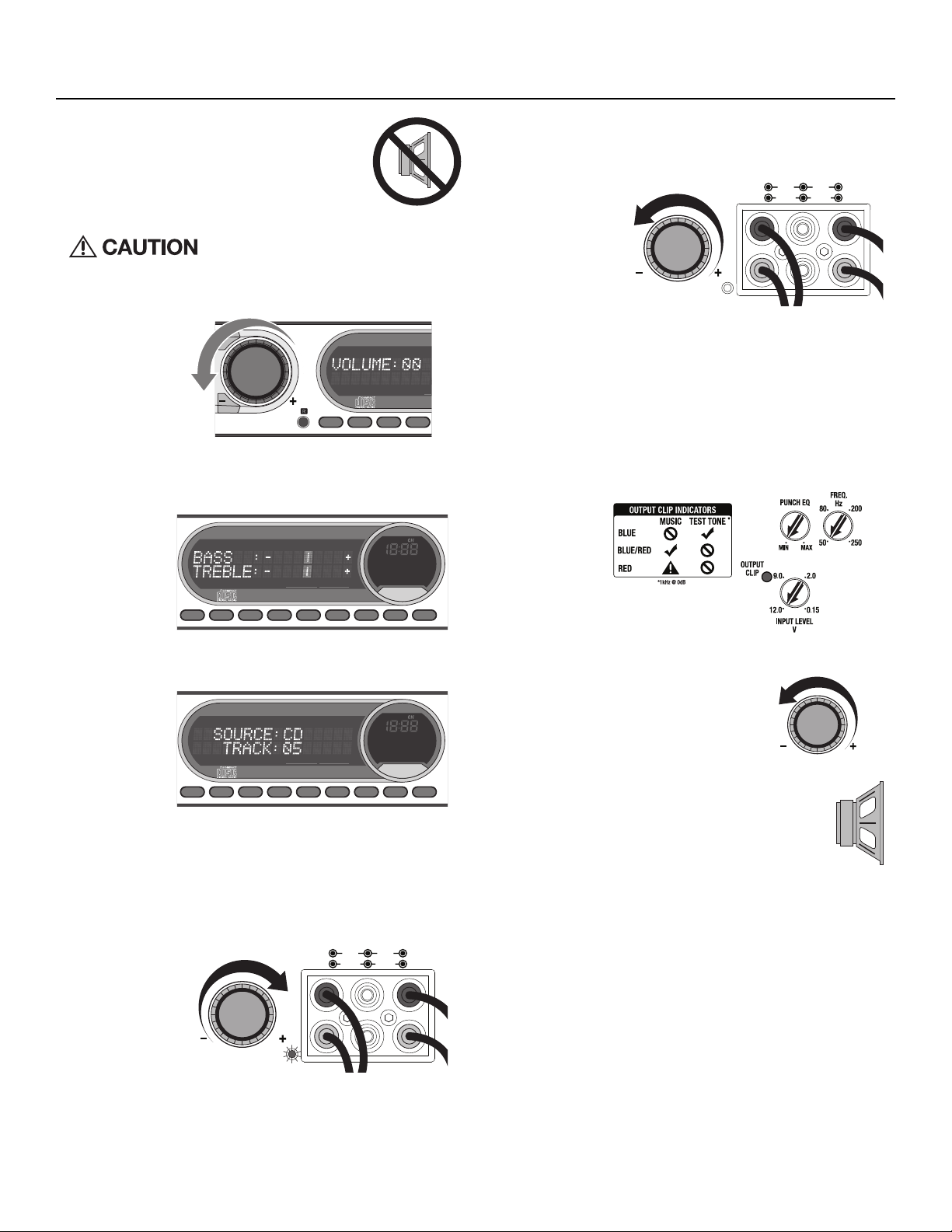
Input Clip Indicator Setup
Step 1. Be sure to disconnect all speakers from the
amplifier.
Failure to comply may cause damage to con-
nected components and/or amplifier.
Step 2. Turn on the source unit with volume set to zero.
Step 3. Adjust the Bass & Treble levels on the source unit to flat.
Step 4. Download test tones at https://rftech.custhelp.com/app/
answers/detail/a_id/1126/. Scroll to the bottom of the page and
download your preferred format.
Note: Use the 40Hz @ 0dB tone (Track 5) for mono amplifier
applications or the 1kHz @ 0dB tone (Track 7) for multi-channel
amplifier applications. Be sure your x-over is switched to the
appropriate filter setting.
Step 5. Increase the source unit volume until the Input Clip Indicator il-
luminates red.
Note: Input Clip can be viewed remotely with optional PLC2.
Step 6. Decrease the source unit volume slightly until the light turns
completely off. This establishes your maximum source unit vol-
ume for adjusting the Output Clip Indicator.
Note: Some source units will not clip.
Output Clip Indicator Setup
Step 7. Be sure to disconnect Punch Level Control - PLC (if equipped)
from the amplifier.
Step 8. Adjust the Input Level knob until the Output Clip Indicator illu-
minates to the appropriate color. Repeat for all channel levels of
input.
Step 9. Turn the source unit volume down.
Step 10. Reconnect all speakers and Punch Level Control
- PLC (if equipped) to the amplifier. Be sure to
maintain proper speaker polarity.
Operation
illus.-3.1
illus.-3.2
illus.-3.3
illus.-3.4
illus.-3.5
illus.-3.6
illus.-3.9
illus.-3.8
illus.-3.7
Volume
Volume
REMOTE
PUNCH LEVEL
INPUT CLIP PASS-THRU REARFRONT
RIGHT
LEFT
RIGHT
LEFT
PLC-OUTPLC-IN
REMOTE
PUNCH LEVEL
INPUT CLIP PASS-THRU REARFRONT
RIGHT
LEFT
RIGHT
LEFT
PLC-OUTPLC-IN
Volume
Volume
Loading ...
Loading ...
Loading ...