Loading ...
Loading ...
Loading ...
8
installation manual
2
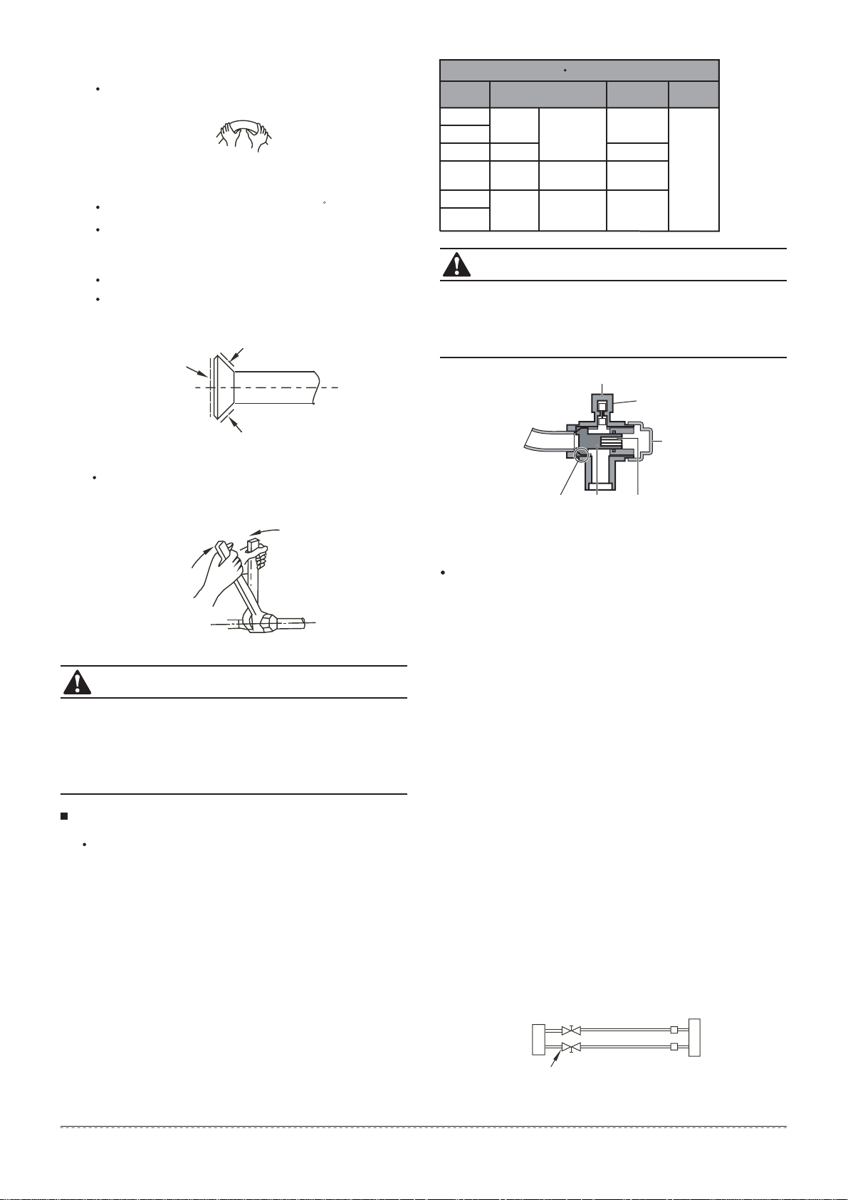
Bend the tubing in proper way. Do not harm to them.
Connect the indoor unit at first, then the outdoor
unit.
Too large torque will harm the bellmouthing and too small
will cause leakage. Please determine the torque
according to Table 4.
After the connecting work is finished, be sure to check
that there is no gas leak.
The bending angle should not exceed 90.
Bending position is preferably in the middle of the
bendable pipe. The larger the bending radius the better it
is.
Do not bend the pipe more than three times.
When connecting the flare nut, coat the flare both inside
and outside with either oil or ester oil and initially tighten
by hand 3 or 4 turns before tighting firmly.
Bend the pipe with thumb
min-radius 100mm
How to expel the air with a vacuum pump
Stop valve operation introduction
1. Opening stop valve
1.
2.
3.
Remove the cap and turn the valve counter
clock-wise with the hexagon wrench.
Turn it until the shaft stops.Do not apply excessive force
to the stop valve. Doing so may break the valve body,
as the valve is not a backseat type. Always use the
special tool.
Make sure to tighten the cap securely.
Fig.7-6
Fig.7-7
Fig.7-8
Be sure to use both a spanner and torque wrench
together when connecting or disconnecting pipes to /from
the unit.
Make sure to tighten the cap securely.
For the tightening torque,refer to the table below.
2. Closing stop valve
1.
2.
Remove the cap and turn the valve clockwise with the
hexagon wrench.
Securely tighten the valve until the shaft contacts the
main bodyseal.
CAUTION
CAUTION
Always use a charge hose for service port connection.
After tightening the cap, check that no refrigerant leaks
arepresent.
Table 7-3
Tightening torque N M (Turn clockwise to close)
Stop
Valve size Shaft (valve body)
Cap
(Valve lid)
Ø6.35
Hexagonal
wrench 4 mm
Ø9.52
Ø12.7
Ø15.9
Hexagonal
wrench 6 mm
Ø22.2 Hexagonal
wrench
10 mm
Ø25.4
Maintenance
nut
36~44
23~27
18~22
13.5~16.5
5.4~6.6
8.1~9.9
13.5~16.5
27~33
11.5~13.9
1
2
4
3
5
7
6
Using the vacuum pump
Loosen and remove the maintenance nuts of stop valves A
and B, and connect the charge hose of the manifold valve to
the service port of stop valve A. (Be sure that stop valves A
and B are both closed)
Connect the joint of the charge hose with the vacuum pump.
Open the Lo-lever of the manifold value completely.
Turn on the vacuum pump. At the beginning of pumping,
loosen the maintenance nut of stop valve B a little to check
whether the air comes in (the sound of the pump changes,
and the indicator of compound meter turns below zero). Then
fasten the maintenace nut.
When the pumping has finished, close the Lo-lever of the
manifold valve completely and turn off the vacuum
pump.Make pumping for 15 minutes or more and check that
the compound meter indicates -76cmHg(-1X10 Pa)
Loosen and remove the cap of stop valves A and B to open
stop valve A and B completely, then fasten the cap.
Disassemble the charge hose from the service port of stop
valve A, and fasten the nut.
5
Fig.7-10
Fig.7-9
service port
cap
maintenance nut
Stop valve
Gas side
Liquid side
hexagon holeshaftseal
Outdoor
unit
Indoor
unit
A
C
D
B
Loading ...
Loading ...
Loading ...