Loading ...
Loading ...
Loading ...
EN
W415-4001 / 08.11.21
11
installation planning
2.3 gas installation
• Risk of fi re, explosion, or asphyxiation. Ensure there are no ignition sources such as sparks or open fl ames.
• Support gas control when attaching gas supply pipe to prevent damaging gas line.
• Always light the pilot whether for the fi rst time or if the gas supply has run out with the glass door opened
or removed. Purging of the gas supply line should be performed by a qualifi ed service technician. Ensure
that a continuous gas fl ow is at the burner before closing the door. Ensure adequate ventilation. For gas and
electrical locations, see “dimensions” section.
• All gas connections must be contained within the appliance when complete (gas fi replaces only).
• High pressure will damage valve. Disconnect gas supply piping before testing gas line at test pressures above
1/2 PSIG.
• Valve settings have been factory set, do not change.
Installation and servicing to be done by a qualifi ed installer.
• Move the appliance into position and secure.
• If equipped with a fl ex connector, the appliance is designed to accept a 1/2” (13mm) gas supply. Without the
connector, it is designed to accept a 3/8” (9.5mm) gas supply. The appliance is equipped with a manual shut
off valve to turn off the gas supply to the appliance.
• Connect the gas supply in accordance to local codes. In the absence of local codes, install to the current
CAN/CSA-B149.1 Installation Code in Canada or to the current National Fuel Gas Code, ANSI Z223.1 / NFPA
54 in the United States.
• When fl exing any gas line, support the gas valve so that the lines are not bent or kinked.
• The gas line fl ex-connector should be installed to provide suffi cient movement for shifting the burner assembly
on its side to aid with servicing components.
• Check for gas leaks by brushing on a soap and water solution. Do not use open fl ame.
• This appliance is designed to accept a 1/2" (13mm) gas supply. The appliance is also equipped with a manual
shut-off valve to turn off the gas supply to the appliance.
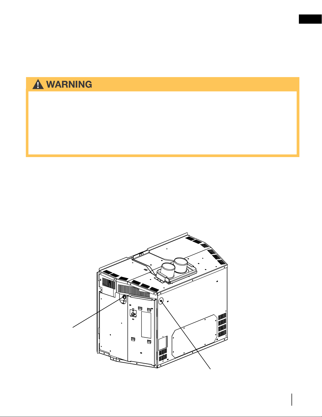
Turn brass elbow until it
lines up with the hole in
the back. Use a backup
wrench on the ball valve
fi tting.
Alternate gas knockout for
rear gas installation.
We recommend the following method of sealing off the damper area around the liner:
Measure the throat of the appliance and mark this shape on a piece of 24 gauge sheet metal (fl ue cover). Cut a 6
3/4" (171mm) hole to lie directly below the appliance fl ue opening. Allow 2" of material for a fl ange on all sides and
cut to these measurements. Bend down the fl anges. If you have never done this before, it might be a good idea to
make a cardboard pattern and test it fi rst. Fasten this fl ue cover in position as high as possible with two masonry
screws per side through the fl anges into the appliance.
Loading ...
Loading ...
Loading ...