Loading ...
Loading ...
Loading ...
6
Installation
1. Plan the wire routing. Keep RCA cables close together but isolated
from the amplifier’s power cables and any high power auto accessories,
especially electric motors. This is done to prevent coupling the noise
from radiated electrical fields into the audio signal. When feeding
the wires through the firewall or any metal barrier, protect them with
plastic or rubber grommets to prevent short circuits. Leave the wires
long at this point to adjust for a precise fit at a later time.
2. Prepare the RED wire (power cable) for attachment to the amplifier by
stripping 1/2” of insulation from the end of the wire. Insert the bared
wire into the B+ terminal of the power connector and tighten the set
screw to secure the cable in place.
NOTE: The B+ cable MUST be fused 18” or less from the vehicle’s battery.
Install the fuseholder under the hood and ensure connections are water
tight.
3. Trim the RED wire (power cable) within 18” of the battery and splice in
a inline fuse holder (not supplied). See Specifications for the rating of
the fuse to be used. DO NOT install the fuse at this time.
4. Strip 1/2” from the battery end of the power cable and crimp an
appropriate size ring terminal to the cable. Use the ring terminal to
connect to the battery positive terminal.
5. Prepare the BLACK wire (Ground cable) for attachment to the amplifier
by stripping 1/2” of insulation from the end of the wire. Insert the bare
wire into the GROUND terminal of the power connector and tighten
the set screw to secure the cable in place. Prepare the chassis ground
by scraping any paint from the metal surface and thoroughly clean the
area of all dirt and grease. Strip the other end of the wire and attach a
ring connector. Fasten the cable to the chassis using a non-anodized
screw and a star washer.
NOTE: Keep the length of the BLACK wire (Ground) as short as possible.
Always less than 30”.
6. Prepare the Remote turn-on wire for attachment to the amplifier by
stripping 1/2” of insulation from the end of the wire. Insert the bared
wire into the REMOTE terminal of the power connector and tighten
the set screw to secure the wire in place. Connect the other end of
the Remote wire to a switched 12 volt positive source. The switched
voltage is usually taken from the source unit’s remote amp on lead. If
the source unit does not have this output available, the recommended
solution is to wire a mechanical switch in line with a 12 volt source to
activate the amplifier.
NOTE: In the event that a switched +12V is not available, either DC offset
or Audio sense can be selected for amplifier turn-on.
7. Connect the power connector to the mating connector at the amplifier.
8. Connect from source signal by plugging the RCA cables into the RCA/
Speaker Harness input jacks, then insert the four pin Molex connector
into the mating four pin INPUT connector at the amplifier.
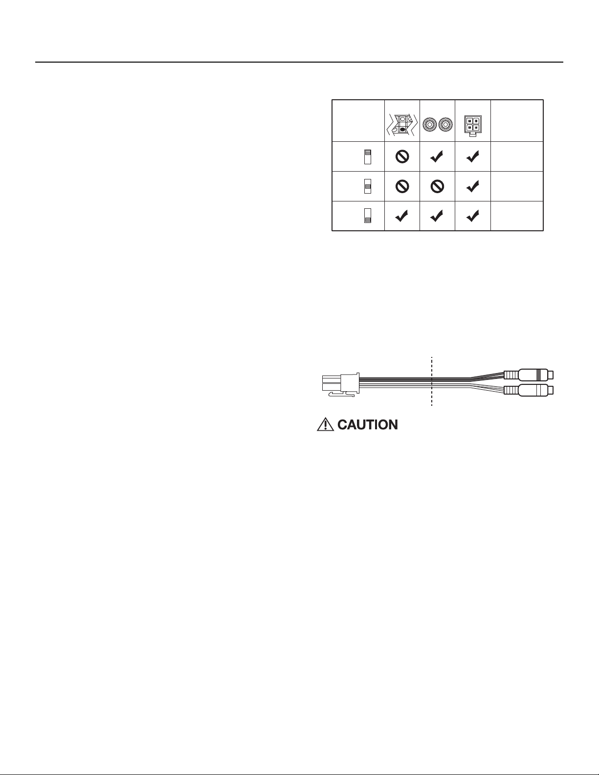
NOTE: When the installation requires a High Level(Speaker) input, the
RCA/Speaker Harness will need to be cut on the speaker wire side of the y-
splitter.Then connect the white to the left(+), white/black to the left(-), grey
to the right(+), and grey/black to the right(-) corresponding vehicle wires.
Always ensure power is off or disconnected at
the amplifier before connecting RCA cables.
Failure to do so may cause damage to the am-
plifier and/or connected components.
9. Perform a final check of the completed system wiring to ensure that all
connections are accurate. Check all power and ground connections
for frayed wires and loose connections which could cause problems.
Install inline fuse near battery connection.
illus.-3.1
Cut
illus.-4.1
LOW INPUT
HI-LEVEL
INPUT
AUTO TURN ON NOTES
Requires 4mV signal
Needs 6V DC on
factory speaker wires
Use hi-level or low-
level input
AUDIO
DC OFFSET
REM
AUDIO
DC OFFSET
REM
AUDIO
DC OFFSET
REM
REM
Loading ...
Loading ...
Loading ...