User Manual Dryer
Installation requirements
Read through the following instructions before installing the dryer and keep this manual for future reference.
WARNING
The control board and inlet valve are intentionally not grounded and may present a risk of electric shock only during servicing.
Service personnel - Do not contact these parts while the appliance is energized.
Key installation requirements
- A grounded electrical outlet.
- A power cord for electric dryers (except in Canada).
- Gas lines (for gas models) must meet national and local regulations.
- An exhaust system made of rigid metal or flexible stiff-walled metal exhaust duct.
WARNING
Remove the door from all discarded appliances to prevent a child from suffocating.
Location considerations
The dryer should be located where there is enough space at the front for loading the dryer, and enough space behind for the exhaust system. This dryer is factory�ready for the rear exhaust option. To exhaust out the bottom, right or left, use the accessory exhaust kit. Instructions are included with the kit. Make sure the room in which the dryer is located has enough fresh air. The dryer must be located where there are no air-flow obstructions. For gas dryers, adequate clearance must be maintained as noted on the data plate to ensure adequate air for combustion and proper dryer operation.
The dryer must not be installed or stored in an area where it will be exposed to water and/or weather. The dryer area must be kept clear of combustible materials, gasoline, and other flammable vapors and liquids. A dryer produces combustible lint. The area around the dryer should be kept lint-free.
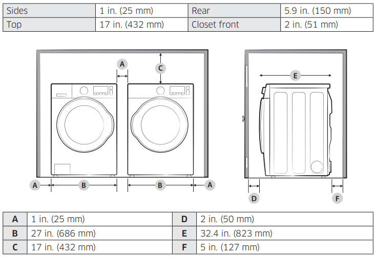
Alcove or closet installations
WARNING
- The dryer must be exhausted to the outside to reduce the risk of fire when installed in an alcove or closet.
- No other fuel-burning appliance should be installed in the same closet as the dryer.
Minimum clearances between the dryer and adjacent walls or other surfaces:
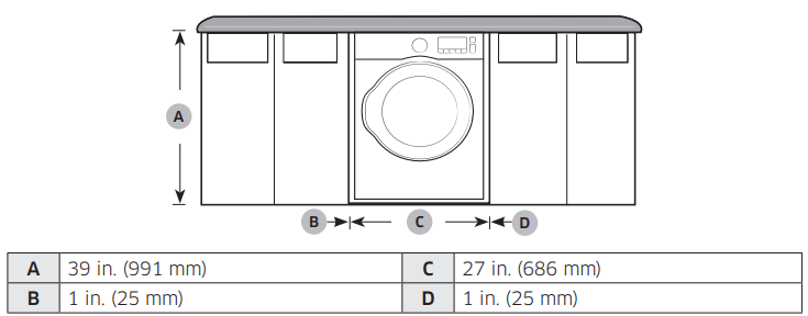
Undercounter installation
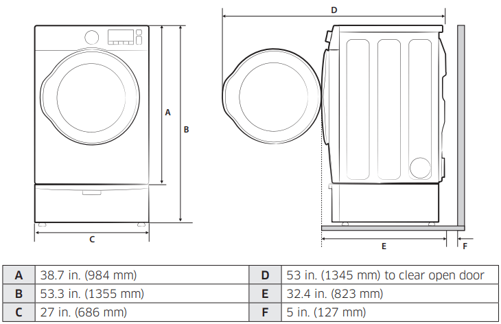
Installation with pedestal
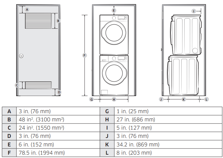
Installation with stacked washing machine and dryer
NOTE
The front of the closet must have two unobstructed air openings (B, C) for a combined minimum total area of 72 in² (465 cm²) with a minimum clearance of 3 in. (7.6 cm) at the top (A) and bottom (D).
External exhaust elbow requires additional space (L).
NOTE
Stacking (MODEL NO: SKK-7A)
Samsung’s Washer and Dryer can be stacked to maximize usable space. You can purchase an optional stacking kit from your Samsung retailer. For details about stacking and compatible models, refer to the user manual included in the stacking kit you purchase.
Ducting requirements
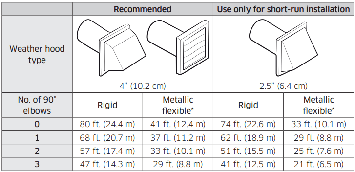
NOTE
* Use a 4-inch (10.2 cm) diameter rigid aluminum or galvanized steel duct.
If you integrate the dryer’s vent system with an existing exhaust system:
- Make sure the exhaust system meets all applicable local, state, and national regulations.
- Verify you are not using a flexible plastic duct.
- Make sure to check for and remove all lint buildup from inside the existing ducts.
- Confirm the duct is not kinked or crushed.
- Make sure the exhaust hood damper opens and closes freely.
Manometer measurements
The static pressure in any exhaust system must not exceed 0.83 inches of water column or be less than 0. Note that these values are measured with the dryer running with a manometer presented to the exhaust duct that connects to the dryer. The dryer tumbler must be empty and the lint filter clean.
Exhausting requirements
The dryer must not be exhausted into a chimney, a wall, a ceiling, an attic, a crawl space, or a concealed space of a building. Exhausting the dryer to the outside will prevent large amounts of lint and moisture from being blown into the room.
In the United States and Canada
- All dryers must be exhausted to the outside.
- The required exhaust duct is 4 inches (10.2 cm) in diameter.
- See “Ducting requirements” in the “Installation” section for the maximum duct length and number of bends that can be used.
- The total length of the flexible metal duct must not exceed 7’ 10½” (2.4 m).
- Do not assemble the duct with screws or other fasteners that extend into the duct and catch lint.
- For the United States only: Use only those foil-type flexible ducts, if any, specifically identified for use with the appliance by the manufacturer and that comply with the Outline for Clothes Dryer Transition Duct. Use Subject 2158A.
Outside the United States and Canada
- Refer to the local codes.
WARNING
- You must exhaust the dryer to the outside to reduce the risk of fire when you install the dryer in an alcove or closet.
- Do not use a plastic or non-metal flexible duct.
- If your existing ductwork is plastic, non-metal, or combustible, replace it with metal.
- Use only a metal exhaust duct that is non-flammable to ensure the containment of exhaust air, heat, and lint.
Gas requirements
WARNING
- Use only natural or LP (liquid propane) gases.
- THE INSTALLATION MUST CONFORM WITH LOCAL CODES, OR IN THE ABSENCE OF LOCAL CODES, WITH THE NATIONAL FUEL GAS CODE ANSI/ Z223.1, THE LATEST REVISION (FOR THE UNITED STATES), OR WITH THE CAN / CGA-B149 INSTALLATION CODES (FOR CANADA).
- Gas dryers are equipped with a burner vent for use with natural gas. If you plan to use your dryer with LP (liquid propane) gas, it must be converted for safe and proper performance by a qualified service technician.
- A 1/2” (1.27 cm) gas supply line is recommended and must be reduced to connect to the 3/8” (1 cm) gas line on your dryer. The National Fuel Gas Code requires that an accessible, approved manual gas shut-off valve be installed within 6” of your dryer.
- Gas dryers installed in residential garages must be raised 18 inches (46 cm) above the floor.
- Additionally, a 1/8” (0.3 cm) N.P.T. (National Pipe Thread) plugged tapping, accessible for test gauge connection, must be installed immediately upstream of your dryer’s gas supply connection.
- Your dryer must be disconnected from the gas supply pipe system during any pressure testing of the system.
- Do not reuse old flexible metal gas lines. Flexible gas lines must be design certified by the American Gas Association (CGA in Canada).
NOTE
- Your dryer uses an automatic ignition system to ignite the burner. There is no constant burning pilot.
- Any pipe joint compound used must be resistant to the action of any liquefied petroleum gas.
- As a courtesy, most local gas utilities will inspect a gas appliance installation.
Commonwealth of Massachusetts installation instructions
Your dryer must be installed by a licensed plumber or gas fitter. A “T” handle manual gas valve must be installed in the gas supply line to your dryer. If a flexible gas connector is used to install your dryer, the connector can be no longer than 3’ (36”).
WARNING
- Gas leaks may occur in your system, creating a dangerous situation.
- Gas leaks may not be detected by smell alone.
- Gas suppliers recommend you purchase and install a UL-approved gas detector.
- Install and use in accordance with the manufacturer’s instructions.
Electrical requirements
The wiring diagram is located on the plate under the control panel or rear frame.
WARNING
- Improperly connecting the equipment grounding conductor can result in a risk of electric shock. Check with a qualified electrician or serviceman if you are in doubt as to whether your dryer is properly grounded. Do not modify the plug provided with your dryer – if it doesn’t fit the outlet, have a proper outlet installed by a qualified electrician.
- To prevent unnecessary risk of fire, electrical shock, or personal injury, all wiring and grounding must be done in accordance with local codes, or in the absence of local codes, in accordance with the National Electrical Code, ANSI/ NFPA No. 70-Latest Revision (for the U.S.) or the Canadian Electrical Code CSA C22.1 – Latest Revisions and local codes and ordinances. It is your responsibility to provide adequate electrical service for your dryer.
- All gas installations must be done in accordance with the National Fuel Code ANSI/Z2231 – Latest Revision (for the U.S.) or CAN/CGA – B149 Installation Codes – Latest Revision (for Canada) and local codes and ordinances.
Grounding
This dryer must be grounded. In the event of a malfunction or breakdown, the ground will reduce the risk of electrical shock by providing a path of least resistance for the electrical current.
Gas models
WARNING
- Your dryer has a cord with an equipment-grounding conductor and a grounding plug. The plug must be plugged into an appropriate outlet that is properly installed and grounded in accordance with all local codes and ordinances.
- Do not modify the plug provided with your dryer – if it doesn’t fit the outlet, have a proper outlet installed by a qualified electrician.
- Do not connect the ground wire to plastic plumbing lines, gas lines, or hot water pipes.
Electric models
WARNING
- Your dryer has an optional cord with an equipment-grounding conductor and a grounding plug. This cord is sold separately.
- The plug must be plugged into an appropriate outlet that is properly installed and grounded in accordance with all local codes and ordinances.
- Do not modify the plug provided with your dryer – if it doesn’t fit the outlet, have a proper outlet installed by a qualified electrician.
- If a power cord is not used and the electric dryer is to be permanently wired, the dryer must be connected to a permanently grounded metal wiring system, or an equipment grounding conductor must be run with the circuit conductors and connected to the equipment grounding terminal or lead on the dryer.
Electrical connections
Before operating or testing, follow all grounding instructions in the “Grounding” section. An individual branch (or separate) circuit serving only your dryer is recommended.
Do not use an extension cord.
Gas models – U.S. and Canada
A 120-volt, 60 Hz AC-approved electrical service with a 15-ampere fuse or circuit breaker is required.
Electric models – U.S. only
Most U.S. dryers require a 120 / 240 volt, 60 Hz AC-approved electrical service. Some require 120 / 208 volt, 60 Hz approved electrical service. The electric service requirements can be found on the data label located behind the door. A 30-ampere fuse or circuit breaker on both sides of the line is required.
- If a power cord is used, the cord should be plugged into a 30-ampere receptacle.
- The power cord is not provided with U.S. electric model dryers. This cord is sold separately.
WARNING
Risk of Electric Shock
When local codes allow, you can connect the dryer’s electrical supply with a new power supply cord kit, marked for use with a dryer, that is U.L. listed and rated at a minimum of 120 / 240 volts, 30-amperes with three No. 10 copper wire conductors terminated with closed-loop terminals, open-end spade lugs with turned-up ends, or with tinned leads.
- Do not reuse a power supply cord from an old dryer. The power cord electric supply wiring must be supported at the dryer cabinet by a suitable UL-listed strain relief.
- Grounding through the neutral conductor is prohibited for (1) new branch-circuit installations, (2) mobile homes, (3) recreational vehicles, and (4) areas where local codes prohibit grounding through the neutral conductor. (Use a 4-prong plug for a 4-wire receptacle, NEMA type 14-30R.)
Electric models – Canada Only
- A 120 / 240 volt, 60 Hz AC-approved electrical service fused through a 30-ampere fuse or circuit breaker on both sides of the line is required.
- All Canadian models are shipped with the power cord attached. The power cord should be plugged into a 30-ampere receptacle.
NOTE
In Canada, you may not convert a dryer to 208 volts.
Installation
This dryer must be installed by a qualified technician. The installer is responsible for connecting the dryer to the main power while observing the relevant safety regulations of your area.
What’s included
Make sure all the parts are included in the product package. If you have a problem with the dryer or the accessories, contact a local Samsung service center or retailer.
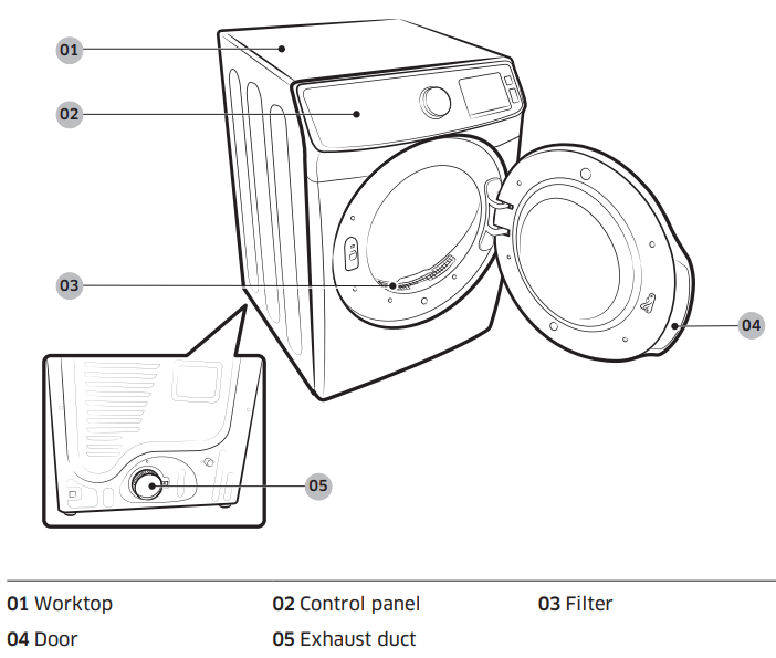
Dryer at a glance
Accessories & tools
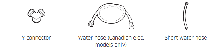
Provided accessories
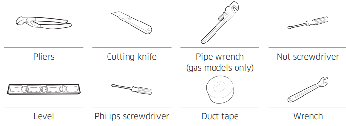
Required tools
WARNING
Packing materials can be dangerous to children. Keep all packing materials (plastic bags, polystyrene, etc.) out of children’s reach.
Step-by-step installation
Make sure you have a qualified technician install the dryer. Step-by-step installation instructions start below.
STEP 1 Install the exhaust system
- Select a location and move the dryer to the site. For easy access, we recommend you install the dryer in the same location as your washer.
- To change the door direction, see “Door reversal”.
- Install the exhaust system as instructed in the “Exhaust ducting guide” section.
NOTE
- To move the dryer easily, lay two of the carton cushions from the packaging on the floor. Tip the dryer on its side so it lies across both cushion tops. Push the dryer so that it is near its final location, and then set the dryer upright.
- The secure room around the dryer facilitates ducting and wiring.
STEP 2 Connect the gas line
First, read through the “Gas requirements” section, and follow these steps.
- Remove the protective cap from the gas pipe.
- Apply an LPG (Liquefied Petroleum Gas)-safe compound or 1.5 wraps of Teflon tape to all threaded connections.
- Connect the gas supply to the dryer. An additional fitting is required to connect the 3/4” (1.9 cm) female thread end of a flexible connector to the 3/8” (1 cm) male threaded end on the dryer. Tighten up the fitting over all threads.
- Turn on the gas supply, and check for any leaks using a soap solution. If a leak is found, tighten the connections and try again. DO NOT use an open flame to check for gas leaks.
STEP 3 Connect the electrical wiring
First, read through the “Electrical requirements” section, and then follow these steps.
3-wire system
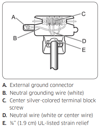
- Loosen or remove the center terminal block.
- Connect the neutral wire (white or center wire) of the power cable to the center, silver-colored terminal screw of the terminal block. Tighten the screws.
- Connect the other wires to the outer terminal block screws. Tighten the screws.
- Tighten the strain relief screws.
- Insert the terminal block cover into the rear panel of the dryer. Then, secure the cover with a hold-down screw.
CAUTION
- To convert from the 4-wire system to the 3-wire system, connect the ground strap to the terminal block support to ground the dryer frame to the neutral conductor.
- Ring-type terminals are recommended. If using strap terminals, make sure they are tightened.
4-wire system
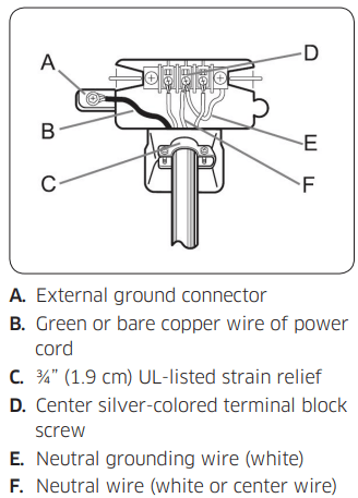
- Remove the external ground connector’s screw, and connect the ground wire (green or unwrapped) of the power cable to the screw.
- CAUTION
- To connect the ground wire to the neutral position without contact A (cabinet ground), contact a technician. This is not user serviceable.
- Ring-type terminals are recommended. If using strap terminals, make sure they are tightened.
- Loosen or remove the screws from the center terminal block.
- Connect the neutral wire (white or center wire) and ground wire (white) to the center screw of the terminal block. Tighten the screw.
- Connect the other wires to the outer terminal block screws. Tighten the screws.
- Tighten the strain relief screws.
- Insert the tab of the terminal block cover into the rear slot of the dryer. Secure the cover with a hold-down screw.
WARNING
- All U.S. models are designed for a 3-wire system connection. The dryer frame is grounded to the neutral conductor at the terminal block. A 4-wire system connection is required for new or remodeled construction, mobile homes, or if local codes do not permit grounding through neutral. If you use the 4-wire system, you cannot ground the dryer frame to the neutral conductor at the terminal block.
- Remove the terminal block cover plate. Insert the power cord with a UL-listed strain relief through the hole provided in the cabinet near the terminal block.
- A strain relief must be used. Do not loosen the nuts already installed on the terminal block. Be sure they are tight. Use a 3/8” (1 cm) deep well socket.
STEP 4 Connect the water hose
The dryer must be connected to a cold water tap using the provided water hoses.
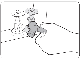
- Close the cold water tap. If you have a washer cold water hose attached to the cold water faucet, unscrew and remove the hose. Then, connect the female end of the Y connector to the cold water tap.
- Connect the straight end of the water hose to the Y connector. Tighten the hose coupling by hand.
- Using pliers, tighten the coupling an additional two-thirds turn. Do not over-tighten. You can damage the coupling.
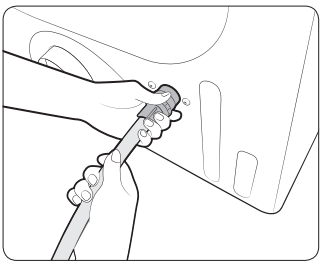
- Connect the angled end of the water hose to the filling valve at the bottom rear of the dryer. Turn the coupling by hand until it is tight.
- Using pliers, tighten the coupling an additional two-thirds turn. Do not over-tighten. You can damage the coupling.
- If you detached the cold water hose from your washer, attach the hose to the open end of the Y connector, tighten the coupling by hand until it is tight, and then, using pliers, tighten an additional two-thirds turn.
- Open the cold water tap, and then check for any leaks.
If the Y connector cannot be directly connected to the cold water tap, use the short hose as shown on the following page.
Using the short hose as an extension
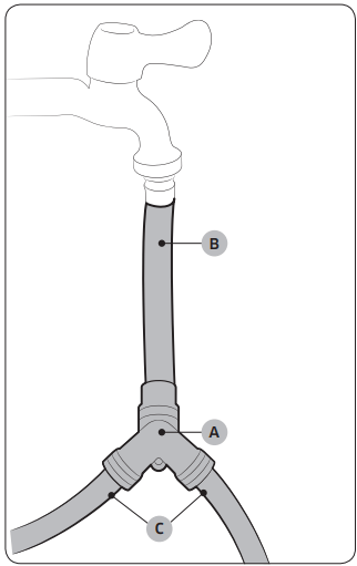
- Close the cold water tap. If you have a washer cold water hose attached to the cold water faucet, unscrew and remove the hose. Then, connect the short hose (B) to the cold water tap. Turn the coupling by hand until it is tight.
- Using pliers, tighten the coupling an additional two-thirds turn. Do not over-tighten. You can damage the coupling.
- Connect the Y connector (A) to the brass male end of the short hose. Turn the coupling by hand until it is tight.
- Using pliers, tighten the coupling an additional two-thirds turn. Do not over-tighten. You can damage the coupling.
- Connect the angled end of the water hoses (C) to the filling valve at the bottom rear of the dryer. Turn the coupling by hand until it is tight.
- Using pliers, tighten the coupling an additional two-thirds turn. Do not over-tighten. You can damage the coupling.
- If you detached the cold water hose from your washer, attach the hose to the free end of the Y connector, tighten the coupling by hand until it is tight, and then, using pliers, tighten an additional two-thirds turn.
- Open the cold water tap, and then check for any leaks.
STEP 5 Level the dryer
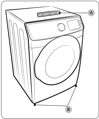
To ensure optimal performance, the dryer must be level.
- Using level (A), check if the dryer is level side to side and then front to back. If the dryer is not level, adjust the leveling feet (B) at the bottom of the dryer. Then, check if the dryer is level again.
NOTE
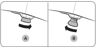
- To set the dryer to the same height as your washer, fully retract (A) the leveling feet by turning them counterclockwise, then loosen (B) the feet by turning them clockwise. Once the dryer is the same height as the washer, follow the directions above to level the dryer.
- Adjust the leveling feet only as much as necessary to level the dryer. Extending the leveling feet more than necessary can cause the dryer to vibrate.
STEP 6 Power on (Gas models)
Make sure all gas connections, the exhaust line, and all wiring are connected correctly. Then, plug the power cord into a power source and check the dryer’s installation and operation using the final checklist in Step 7 below.
STEP 7 Final Check
When the installation is complete, confirm that:
- The dryer is plugged into an electrical outlet and grounded properly.
- The exhaust ductwork is connected and the joints are taped.
- You have used rigid or stiff-walled flexible metal duct material, not plastic flexible duct.
- The dryer is level and is sitting firmly on the floor.
- The dryer starts, runs, heats, and shuts off properly.
For gas models:
- Gas is supplied properly with no leaks.
CAUTION
The burner may not ignite initially due to air in the gas line. Allowing your dryer to operate on a heat setting will purge the line. If the gas does not ignite within 5 minutes, turn your dryer off and wait 5 minutes. Be sure the gas supply to your dryer has been turned on. To confirm gas ignition, check the exhaust for heat.
Vent blockage test
After the dryer is installed, start the Vent Blockage Test to check if the duct system is properly installed. The Vent Blockage Test automatically detects the status of the ducts and reports any blockage or problems. Proper ducting can reduce drying time and save energy.
NOTE
The Vent Blockage Test must run with the dryer in a cool state. If the dryer warms up after the installation check, run the AIR FLUFF cycle for several minutes to reduce its internal temperature.
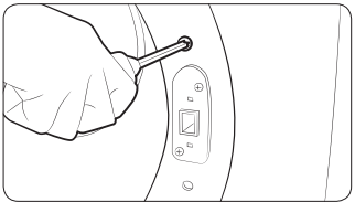
Running the vent blockage test
- Make sure the drum is empty, and then close the door. (If there are any clothes or other items in the drum, the test will not give accurate results.)
- Press the POWER button to turn the dryer on, then simultaneously press and hold the Adjust Time ^ and Dry level buttons for 3 seconds. “InS” appears in the dryer’s display. (If you have started other procedures before the Vent Blockage Test, the dryer will not enter the Vent Blockage Test mode.)
- Press the START/PAUSE button. The Vent Blockage Test starts immediately. During the test, the number indicator makes a circle in 6 clockwise steps. The test takes about 2 minutes. Do not open the door during the test.
- After 2 minutes, when the test is complete, the results are displayed and the dryer sounds a tone. If the status of the duct system is normal, “0” appears and the dryer sounds a completion tone. If the duct system can not exhaust properly, “CLg” appears and the dryer sounds an alarm tone. If there are any other problems, an information code appears in the display. For information about the code, see the Information codes section.
- To stop or cancel the Vent Blockage Test, press the POWER button to turn off your dryer.
- During the test, if “dc” appears in the display, make sure the door is closed. If “C1” is displayed, see if there is laundry inside the drum. If there is, stop the test and remove it. Then, start the test again.
- The results remain on the display for about 5 minutes and then automatically turn off. You can turn the result off immediately by pressing the POWER button.
NOTE
- During or after the test, the internal drum is hot. Use caution to prevent burns. The Vent Blockage Test is used to check for problems with the current duct system when the dryer is installed for the first time.
- If the test result displays “CLg” (the duct system is blocked ), refer to the “Ducting requirements” section and the “Exhaust ducting guide” section below, and then take proper measures to correct any problems. If the test is suspended, it could result in incorrect results. Follow the proper procedures when testing the dryer.
- Even if the test result is normal (“0”), the duct system could be blocked slightly. Properly install all ductwork according to the installation instructions in this manual.
Exhaust ducting guide
Ducting
- Make sure the dryer is installed properly so the air exhausts freely.
- Use 4-inch rigid metal ducts. Tape all joints including the dryer connection. Never use lint-trapping screws.
- To facilitate the exhaust, keep the ducts as straight as possible.
Cleaning
Clean all old ducts before installing the dryer, and make sure the vent flap opens and closes freely. We recommend that you clean the exhaust system annually or on a regular basis.
WARNING
- To prevent fire, do not use plastic, thin-foil, or non-metal flexible ducts of any kind.
- Do not use a poor exhaust system because it slows down the dryer’s performance.
- Do not use excessively long ducts that have multiple elbows.
- Do not use crushed or clogged venting or ducts.
Door reversal
Type 1
- It is recommended to put a soft rug on the floor to prevent scratches on the door.
- Unplug the power cord.
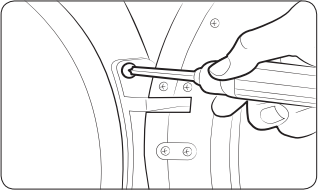
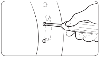
- Remove two door hinge screws.
- Lift the door and remove it. NOTE There is a screw on the back side of the hinge that will support the door as you unscrew the hinge screws.
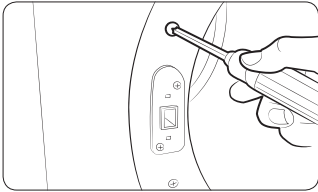
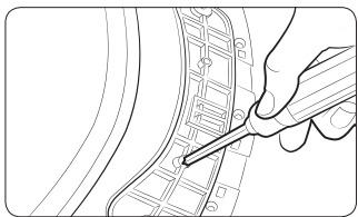
- Remove the two screws that are above and below the cut-out in the frame front.
- Remove the two screws above and below the lever holder on the opposite side of the door opening.
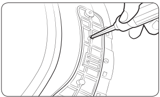
- Remove the two screws that hold the lever holder in place, and then remove the lever holder.
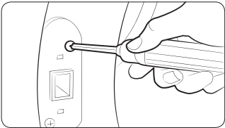
- Re-insert the two screws that held the lever holder into the same screw holes, and then tighten.
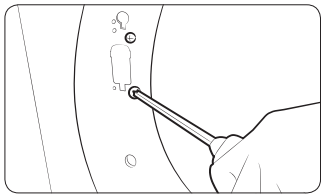
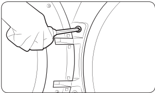
- Remove the single screw from the back of the door hinge. NOTE This is the screw that supports the door against the frame so you can unscrew or screw in the hinge without needing to support the door yourself.
- Insert the screw you just removed into the other screw hole on the back of the door hinge, and then tighten.
- Place the door on the other side, and then reattach it to the dryer. NOTE Insert the head of the screw on the back of the hinge into the hole above the cut-out in the frame, and then slide the door hinge down until it stops. Make sure the protrusion on the back of the hinge is pressed into the cut-out before you tighten the hinge screws.
- Push the lever holder into the cut-out on the other side of the door opening. Insert screws, and then tighten as shown.
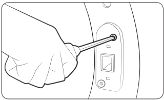
- Re-attach the remaining screws to the remaining holes above and below the lever holder, and then tighten them.
Operations
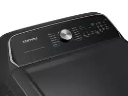
Feature panel
DVE(G)45M5500*
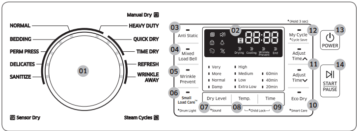
DVE(G)45N5300*
NOTE
Extremely tangled items finished by the washer may degrade the drying efficiency or cause the door to open. We recommend that you untangle the items before drying.
Do not put objects on the dryer, especially on the feature panel.
CAUTION
Do not spray water onto the feature panel. This may cause a system failure.
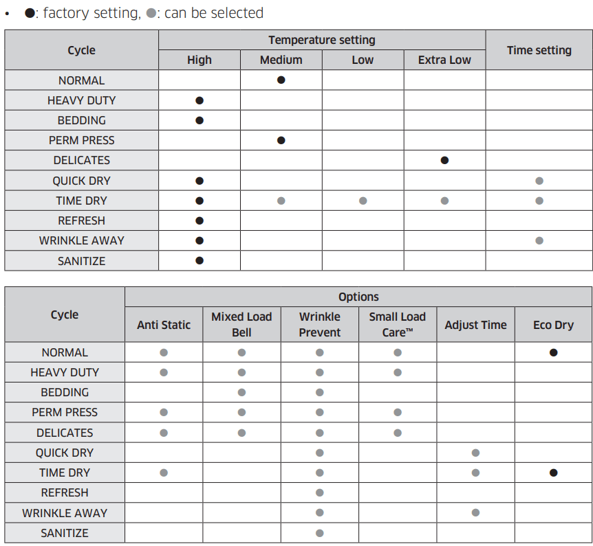
Simple steps to start
- Press POWER to turn on the dryer.
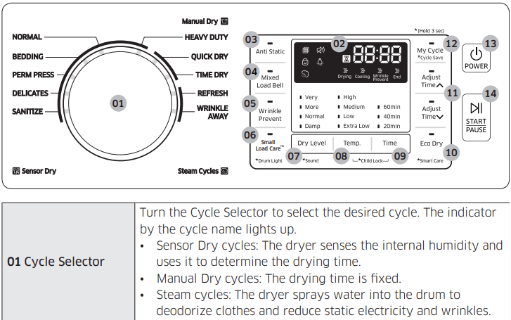
- Turn the Cycle Selector to select a cycle.
- Change the cycle settings (Dry Level, Temp. and Time) as necessary.
- Optionally, you can activate the options available by pressing the relevant button (Anti Static, Mixed Load Bell, Wrinkle Prevent, and/or Eco Dry).
- Press and hold START/PAUSE. The dryer indicator turns on with an estimated cycle time on the display.
To change the cycle during the operation
- Press START/PAUSE to stop the operation.
- Select a different cycle.
- Press and hold START/PAUSE to start a new cycle.
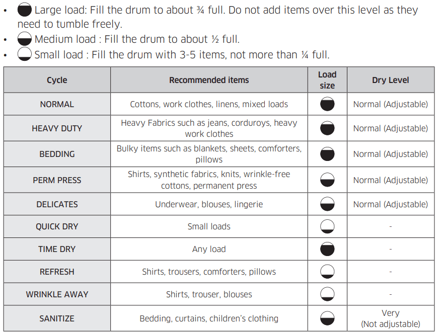
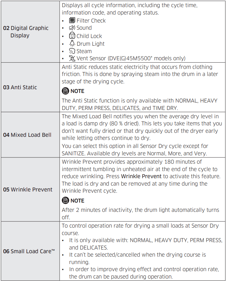
Cycle Overview
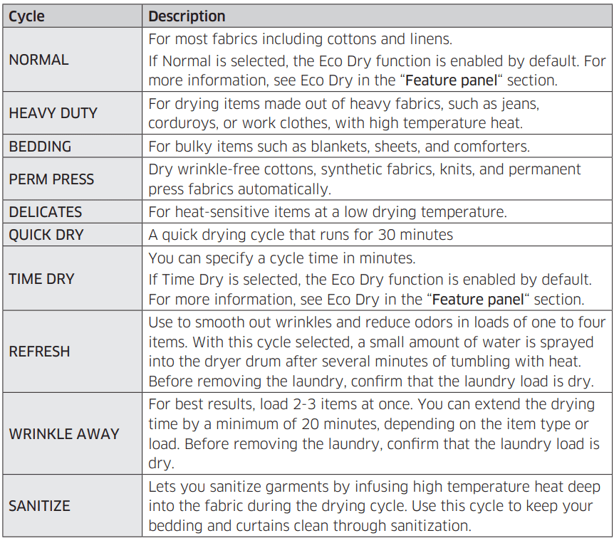
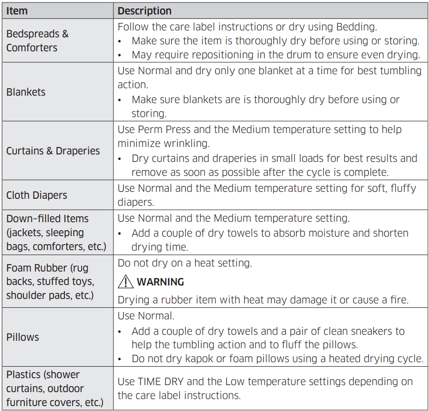
Drying guide
The best way to dry items is to follow the instructions on the care label. If no drying instructions are provided, see the following table for reference.
WARNING
Do not dry:
- Fiberglass items (curtains, draperies, etc.)
- Woolens, unless recommended on the label
- Items spotted or soaked with vegetable or cooking oils
Special features
Child Lock 
Child Lock prevents children from playing with the dryer. When Child Lock is activated, all buttons except for the POWER button are disabled. To activate/deactivate Child Lock, simultaneously press and hold Temp. and Time for 3 seconds.
NOTE
Once Child Lock is activated, it will remain active even after you restart the dryer. If other buttons, except for the POWER button, do not respond, check the Child Lock indicator. If the indicator is on, follow the instructions above to turn Child Lock off.
Smart Care
If the dryer displays an information code, you can use Smart Care to check the status of the dryer on a smartphone. To use Smart Care, you must have the Samsung Smart Care app installed on your smartphone.
NOTE
Smart Care is optimized for Samsung Galaxy and Apple iPhones. (Not compatible with some models).
Download the Samsung Smart Care app from the Google Play Store or Apple App store (Search term: “Samsung Smart Washer/Dryer”), and install it on your smartphone.
If an information code appears on the dryer, follow these steps:
- Press and hold Eco Dry for 3 seconds to activate Smart Care. The Smart Care indicator turns on.
- Open the Smart Care app on your smartphone.
- Put the smartphone’s camera close to the display of the dryer. The app automatically recognizes the information code and displays suggestions on your smartphone.
- If the smartphone fails to recognize the information code more than twice, type the information code manually into the Smart Care app.
CAUTION
- If the light is reflected on the display of the dryer, the smartphone may not recognize the information code.
- If you hold the smartphone at an angle to the dryer’s display, the smartphone may not recognize the information code. For best results, hold the smartphone so that the front of the panel and the smartphone are parallel or nearly parallel.
- After you use this function, the dryer will delete the record of the information code from its code log.
Sound On/Off
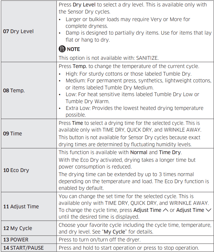
To turn off the dryer’s notification beeps and melodies, press and hold Dry Level for 3 seconds.
To unmute the dryer, press and hold Dry Level again for 3 seconds.
NOTE
This function remains active even after you restart the dryer.
Drum Light
To turn on the drum light while the dryer is running, press and hold Small Load Care™ for 3 seconds.
NOTE
After 2 minutes of inactivity, the drum light automatically turns off.
My Cycle
You can create your own cycle that contains your preferred settings, and use it at your convenience.
- Turn the Cycle Selector to select a cycle. The cycle indicator turns on.
- Set or change the settings (Dry Level, Temp., Time, etc) and/or options as necessary. Each corresponding indicator blinks.
- Press and hold My Cycle for 3 seconds. The dryer stores the selected cycle with its settings.
To use My Cycle, press My Cycle.
NOTE
Wrinkle Prevent is not available with My Cycle.
Maintenance
Keep the dryer clean to prevent decreased performance and to lengthen its life.
WARNING
The control board and inlet valve are intentionally not grounded and may present a risk of electric shock only during servicing.
Service personnel - Do not contact these parts while the dryer is energized.
Vent sensor (DVE(G)45M5500* models only)
The dryer features a vent sensor that detects and notifies you when it is time to clean the ductwork.
The  indicator lets you know the status of the duct.
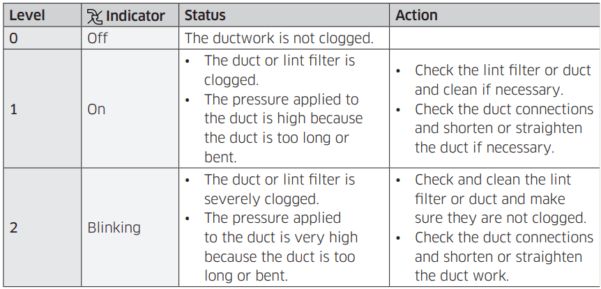
If the dryer is in the Level 2 state, the indicator blinks for 3 hours after the completion of the current cycle. If you press POWER or open the door, the dryer powers off immediately.
NOTE
- For duct installation, see “Exhaust ducting guide” and “Ducting requirements” o
- The dryer may keep running even if the duct is clogged, but the drying time will be extended.
- If the indicator turns on for the first time and is solid (not blinking), check and clean the lint filter and/or duct.
- If the indicator turns on again later, it is because the duct is installed or connected with some restrictions (it’s too long or has too many bends). This is not a system failure. However, the drying time may be extended or the drying performance may be degraded.
Cleaning
Feature panel
- Clean with a soft, damp cloth. Do not use abrasive substances.
- Do not spray liquid cleaning agents directly on the display of the dryer.
- Some laundry pre-treatment soil and stain removers may damage the feature panel.
- When using liquid cleaning agents, apply them to the cleaning cloth. Do not apply them directly to the dryer. Wipe up any spills or overspray immediately.
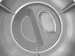
Tumbler
- Remove any stains from the tumbler with an all-purpose cleaner.
- Tumble old towels or rags to remove any remaining stains or cleaning substances. Stains may still be visible, but will not affect subsequent loads.
Powder coat tumbler
To clean the powder coat tumbler, use a damp cloth with a mild, non-abrasive cleaner suitable for easily marred surfaces. Remove cleaner residue and dry with a clean cloth.
Dryer exterior
- Clean with a soft, damp cloth. Do not use abrasive substances.
- Protect the surface from sharp objects.
- Do not place any heavy or sharp objects or a detergent container on the dryer. They can scratch or damage the top cover of the dryer.
- The dryer has a high-gloss finish on the entire surface. Be careful not to scratch or damage the surface.
Exhaust system
- Check and clean the exhaust system on a yearly or regular basis to maintain optimum performance.
- The external exhaust hood must be cleaned more frequently to ensure proper airflow.
Troubleshooting
Checkpoints
If the dryer operates abnormally, first check the list of problems in the table below and try the suggested actions.
Does not run.
- Make sure the door is latched shut.
- Make sure the power cord is plugged into a live electrical outlet.
- Check your home’s circuit breakers or fuses.
- Press or tap START/PAUSE again if the door was opened during a cycle.
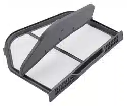
- Clean the lint filter.
Does not heat.
- Check your home’s circuit breakers or fuses.
- Some cycles do not require heat. Check the selected cycle again.
- For a gas dryer, make sure the gas supply is on.
- Clean the lint filter and exhaust duct.
- The dryer may have moved into the cool-down phase of the cycle.
Does not dry.
- Check all of the above, plus...
- Make sure the exhaust hood outside your home can open and close freely.
- Check the exhaust system for lint buildup. Ducting should be inspected and cleaned annually.
- Use a 4” rigid metal exhaust duct.
- Do not overload. 1 wash load = 1 dryer load.
- Dry heavy items and lightweight items separately.
- Large, bulky items, such as blankets or comforters, may require repositioning to ensure even drying.
- Make sure that your washer is draining properly and extracting adequate water from the load.
- The load may be too small to tumble properly. Add a few towels and restart the dryer.
- The load may be too large to tumble properly. Remove some items and restart the dryer.
- Clean the lint filter.
Is noisy.
- Check the load for objects such as coins, loose buttons, nails, etc. Remove promptly.
- It is normal to hear the dryer gas valve or heating element cycle on and off during the drying cycle.
- Make sure the dryer is leveled properly as outlined in the installation instructions.
- It is normal for the dryer to hum due to the high velocity of air moving through the dryer drum, fan, or exhaust system.
Dries unevenly.
- Seams, pockets, and other similarly heavy areas may not be completely dry when the rest of the load has reached the selected dryness level. This is normal. You can choose a higher dryness level or a cycle that involves a higher dryness level.
- If one heavy item is dried with a lightweight load, such as one towel with sheets, it is possible that the heavy item will not be completely dry when the rest of the load has reached the selected dryness level.
- For the best drying results, dry heavy items and lightweight items separately.
Has odors.
- Household odors from paint, varnish, strong cleaners, etc. may enter the dryer with the surrounding room air. This is normal as the dryer draws the air from the room, heats it, pulls it through the tumbler, and exhausts it outside.
- When these odors linger in the air, completely ventilate the room before using the dryer.
- Use a cycle featuring the Refresh function. If odors persist, wash and dry the items again.
Lint on clothes.
- Make sure the lint filter is cleaned before every load. For clothes that naturally build up lint, clean the filter during the cycle.
- Some fabrics are lint producers (for example, a fuzzy white cotton towel) and they must be dried separately from clothes that are lint trappers (for example, a pair of black linen pants).
- Divide larger loads into smaller loads for drying.
- Check pockets thoroughly before drying, then dry clothes.
- Remove lint inside the drum before drying a load.
Items still wrinkled after Wrinkle Prevent (Wrinkle Away, Wrinkle Release).
- Small loads of 1 to 4 items work best.
- Load fewer items. Load similar-type items.
- Take out the items immediately after drying is complete.
Water drips from the nozzle when the Steam cycle starts.
- This is steam condensation. The dripping water will stop after a short time.
Sprayed water is not visible during Steam cycles.
- Sprayed water is difficult to see when the door is closed.
Extended time.
- Sensor Dry automatically senses the moisture in the load and shuts the dryer off when the selected dryness level is reached. The drying time can change according to the type and amount of laundry. See the cycle chart for reference.
If a problem persists, contact a local Samsung service center.
Information codes
If the dryer fails to operate, you may see an information code on the display panel. To determine what you should do, check the list of codes in the table below, and then try the suggested actions.
Code DC
- Operating the dryer with the door open.
- Make sure the door is properly closed.
- Make sure laundry is not caught in the door.
Code FC
- Invalid power source frequency
- Try restarting the cycle.
- If this information code remains, contact a Samsung service center.
Code AC
- Electronic control problem (Invalid Communication).
- Contact a Samsung service center.
Code HC
- High-temperature heating check
- Clean the lint filter.
- If this information code remains, contact a Samsung service center.
Code 9C1
- The electronic control needs to be checked.
- Check if power is supplied properly.
- If the information code remains, contact a Samsung service center.
Code tC
- The Thermistor1 resistance is very low or high.
- Check for a clogged lint screen
- Check if the vent system is restricted.
- If this information code remains, contact a Samsung service center.
Code tC5
- The Thermistor2 resistance is very low or high.
- Check for a clogged lint screen.
- Check if the vent system is restricted.
- If this information code remains, contact a Samsung service center.
Code dF
- Incorrect door switch.
- Contact a Samsung service center.
If any information code keeps appearing on the screen, contact a Samsung service center.
Specifications
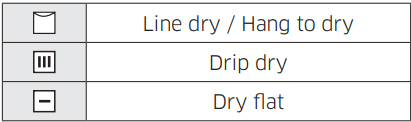
Fabric care chart
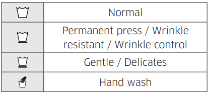
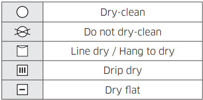
The following symbols provide garment care direction. The clothing care labels include symbols for drying, bleaching, ironing, and dry cleaning. The use of symbols ensures consistency among garment manufacturers of domestic and imported items. Follow care label directions to optimize garment life and reduce laundering problems.
Wash cycle
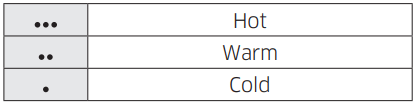
Water temperature
NOTE
The Water Temperature table lists appropriate wash water temperatures for various items. The temperature range is 106 - 126 °F (41 - 52 °C) for Hot, 84 - 106 °F (29 - 41 °C) for Warm, and 61 - 84 °F (16 - 29 °C) for Cold. (Wash water temperature must be a minimum of 61 °F (16 °C) for detergent activation and effective cleaning.)
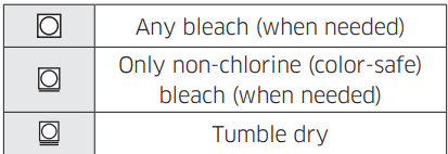
Bleach
Normal
Special instructions
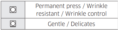
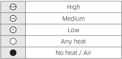
Heat setting
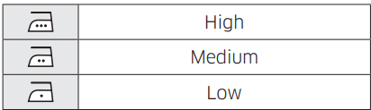
Iron dry or steam temperatures
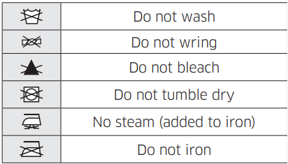
Warning symbols for laundering
Dry-clean
Protecting the environment
This appliance is manufactured from recyclable materials. If you decide to dispose of this appliance, please observe local waste disposal regulations. Cut off the power cord so that the appliance cannot be connected to a power source. Remove the door so that animals and small children cannot get trapped inside the appliance.
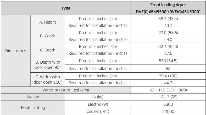
Specification sheet
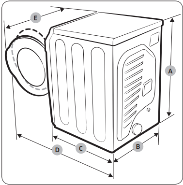
NOTE
“A. Height” Spec can vary from 42.4 to 43.3 inches (107.7 - 108.9 cm) depending on the leveling feet adjustments.
Cycle chart
NOTE
For best results, follow the load size recommendations for each dry cycle.