Loading ...
Loading ...
Loading ...
47
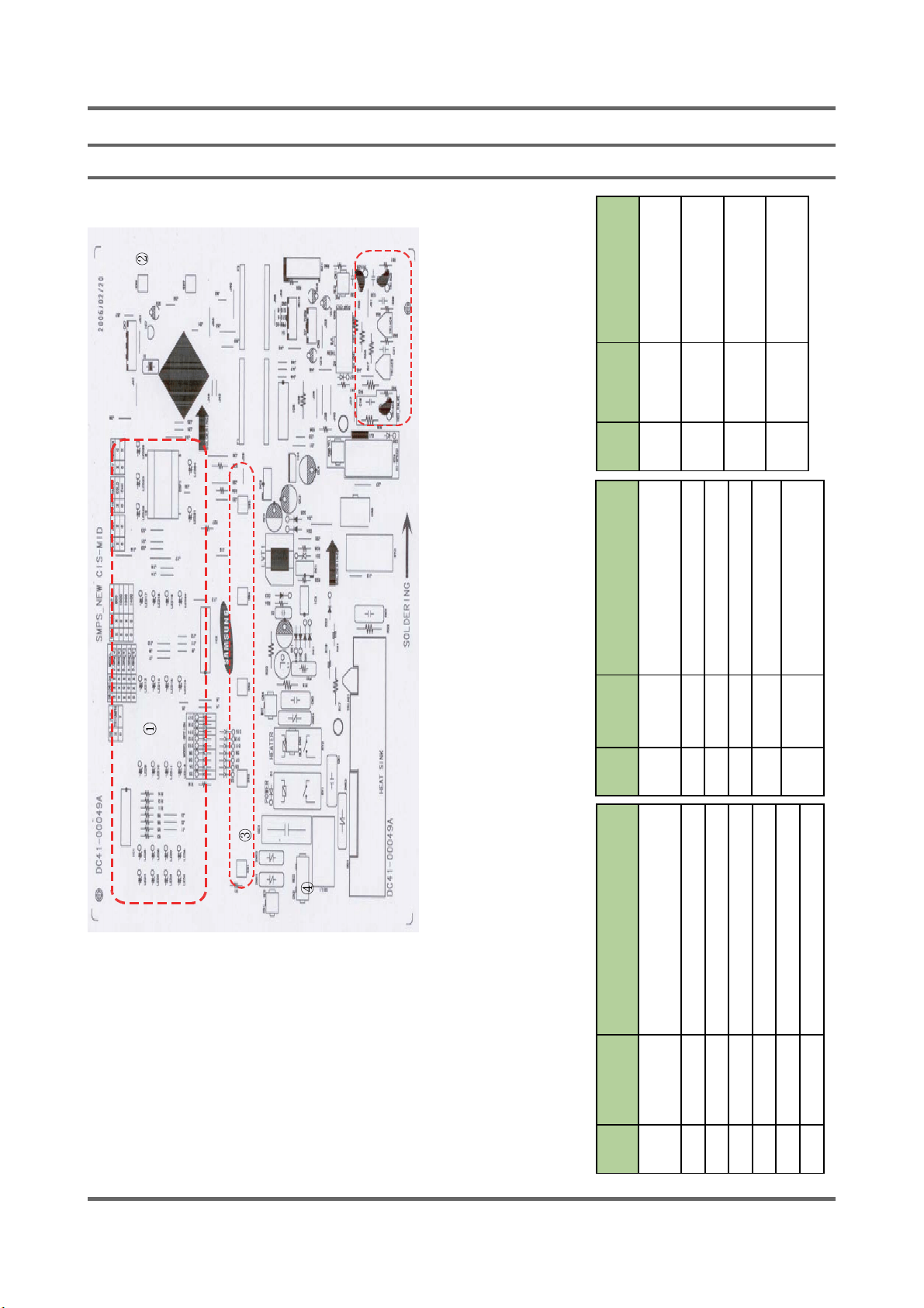
9. WIRING DIAGRAM
9-1. PCB ASSY’ LAYOUT
56
7
8
9
10
11
12
Item Part
Number
Description
1 Display Displays or indicates operations or
functions
2 Power_key Turns the power on/off
3 Start_key Stars/stops an option
4 key Selects and processes each function
5 CN1 Connect to the GND Wire
6 CN2 Detects if the door is open or closed
7 CN4 Connect to the AC1 Wire
Item Part
Number
Description
8 BD1 Convert AC into DC for motor
power
9 Triac2 Control motor on/off
10 RY3 Control direction of motor
11 CN5 Connects to the wire of motor
12 RY4 Control on/off as high RPM
13 Operat-
ing part
Operating parts as cold/hot/
drain/door
Item Part
Number
Description
14 CN8 Connect the driving
system wire
15 CN11 Connect to the pre
valve wire
16 CN10 Connect to the silver
nano wire
17 CN9 Connect to the heat
sink thermistor
Loading ...
Loading ...
Loading ...