The air which is drawn in is cleaned by the grease filters and conveyed to the exterior by a pipe system.
Note: The exhaust air must not be conveyed into a functioning smoke or exhaust gas flue or into a shaft which is used to ventilate installation rooms which contain heat-producing appliances.
Before conveying the exhaust air into a nonfunctioning smoke or exhaust gas flue, obtain the consent of the heating engineer responsible.
If the exhaust air is conveyed through the outer wall, a telescopic wall box should be used.
Air recirculation
The air which is drawn in is cleaned by the grease filters and an activated carbon filter, and is conveyed back into the kitchen.
Note: To bind odours in air recirculation mode, you must install an activated carbon filter. The different options for operating the appliance in air recirculation mode can be found in the brochure. Alternatively, ask your dealer. The required accessories are available from specialist retailers, from customer service or from the Online Shop.
Operating the appliance
These instructions apply to several appliance variants. It is possible that individual features are described which do not apply to your appliance.
Note: Switch on the extractor hood when you start cooking and switch it off again several minutes after you have finished cooking. This is the most effective way of removing the kitchen fumes.
Control panel
Setting the fan
Switching on
Pull out the filter pull-out and press the button. The fan starts at setting 2.
Press the + or - button to change the fan strength.
Switching off
Press the button. Slide the filter pull-out in.
Intensive setting
You can use the intensive setting if there is a large build-up of odours and fumes/vapours.
Press the + button until all of the LEDs in the display light up. The intensive setting is activated.
After approx. six minutes, the electronics automatically reduce the fan to a lower setting . If you want to end the intensive setting before the preset time expires, press the - button until the required fan setting is reached.
The run time is limited. The fan is then automatically reduced to a lower fan setting. You can switch back manually at any time.
Fan run-on time
If you slide in the filter pull-out, the run-on time will be activated for as long as the extractor hood is operating.
After approx. 10 minutes, the fan switches off automatically.
Lighting
The lighting can be switched on and off independently of the ventilation.
Press the button.
Cleaning and maintenance
Warning
Risk of burns!
The appliance will become hot during operation, especially near the bulbs. Allow the appliance to cool down before cleaning.
Warning
Risk of electric shock!
Penetrating moisture may result in an electric shock. Clean the appliance using a damp cloth only. Before cleaning, pull out the mains plug or switch off the circuit breaker in the fuse box.
Warning
Risk of electric shock!
Do not use any high-pressure cleaners or steam cleaners, which can result in an electric shock.
Warning Risk of injury!
Components inside the appliance may have sharp edges. Wear protective gloves.
Cleaning agents
To ensure that the different surfaces are not damaged by using the wrong cleaning agent, observe the information in the table. Do not use any of the following:
Harsh or abrasive cleaning agents,
Cleaning agents with a high alcohol content,
Hard scouring pads or cleaning sponges,
High-pressure cleaners or steam cleaners.
Wash new sponge cloths thoroughly before use.
Follow all instructions and warnings included with the cleaning agents.
Area
Cleaning agent
Stainless steel
Hot soapy water:
Clean with a dish cloth and then dry with a soft cloth.
Clean stainless steel surfaces in the grind direction only.
Special stainless steel cleaning products are available from our after-sales service or from specialist retailers. Apply a very thin layer of the cleaning product with a soft cloth.
Painted surfaces
Hot soapy water:
Clean using a damp dish cloth and dry with a soft cloth/towel.
Do not use any stainless steel cleaners.
Aluminium and plastic
Glass cleaner:
Clean with a soft cloth.
Glass
Glass cleaner:
Clean with a soft cloth. Do not use a glass scraper.
Controls
Hot soapy water:
Clean using a damp dish cloth and dry with a soft cloth/towel.
Risk of electric shock caused by penetrating moisture.
Risk of damage to the electronics from penetrating moisture. Never clean operating controls with a wet cloth.
Do not use any stainless steel cleaners.
Cleaning the metal mesh grease filters
These instructions apply to several appliance variants. It is possible that individual features are described which do not apply to your appliance.
Warning
Risk of fire!
Grease deposits in the grease filter may catch fire.
Clean the grease filter at least every 2 months.
Never operate the appliance without the grease filter. Notes
Do not use any aggressive, acidic or alkaline cleaning agents.
When cleaning the metal mesh grease filters, also clean the holder for the metal mesh grease filters in the appliance using a damp cloth.
The metal mesh grease filters can be cleaned in the dishwasher or by hand.
By hand:
Note: You can use a special grease solvent for stubborn dirt. It can be ordered via the Online Shop.
Soak the metal mesh grease filters in a hot soapy solution.
Clean the filters with a brush and then rinse them thoroughly.
Leave the metal mesh grease filters to drain.
In the dishwasher:
Note: If the metal mesh grease filters are cleaned in the dishwasher, slight discolouration may occur. This has no effect on the function of the metal mesh grease filters.
Do not clean heavily soiled metal mesh grease filters together with utensils.
Place the metal mesh grease filters loosely in the dishwasher. The metal mesh grease filters must not be wedged in.
Removing metal grease filter
1. Open the lock and fold down the metal grease filter. While doing this, place your other hand under the metal grease filter.
2. Take the metal grease filter out of the holder.
Notes
- Fat may accumulate in the bottom of the metal grease filter.
- Hold the metal grease filter level to prevent grease from dripping out.
3. Clean the metal grease filter.
On appliances with a glass plate in the filter pull-out:
The glass plate can be removed easily and can be cleaned in the dishwasher.
To remove it, carefully lift the glass plate.
Installing the metal mesh grease filter
Insert the metal mesh grease filter. While doing this, place the other hand under the metal mesh grease filter.
Fold the metal mesh grease filter upwards, locking it in place.
Trouble shooting
Malfunctions often have simple explanations. Please read the following notes before calling the after-sales service.
Warning
Risk of electric shock!
Incorrect repairs are dangerous. Repairs may only be carried out and damaged power cables replaced by one of our trained after-sales technicians. If the appliance is defective, unplug the appliance from the mains or switch off the circuit breaker in the fuse box. Contact the after-sales service.
Malfunction table
Problem
Possible cause
Solution
The appliance does not work
The plug is not plugged in.
Connect the appliance to the electricity supply
Power cut
Check whether other kitchen appliances are working
Faulty fuse
Check in the fuse box to make sure that the fuse for the appliance is OK
The lighting does not work.
The bulbs are faulty.
For information on changing the bulbs, see the "Replacing Bulbs" section.
Replacing bulbs
These instructions apply to several appliance variants. It is possible that individual features are described which do not apply to your appliance.
Warning
Risk of burns!
Halogen bulbs become very hot when switched on. There is still a risk of burning for some time after they have been switched off. Allow the halogen bulbs to cool down before replacing them.
Warning
Risk of electric shock!
When changing the bulbs, the bulb socket contacts are live. Before changing the bulb, unplug the appliance from the mains or switch off the circuit breaker in the fuse box.
Important! Only use bulbs of the same type and wattage.
Replacing halogen bulbs
Note: When inserting halogen bulbs, do not touch the glass tube. Use a clean cloth to insert the halogen bulbs.
1. Carefully remove the bulb ring using a suitable tool.
2. Pull out the bulb and replace it with a bulb of the same type.
3. Insert the bulb cover.
4. Insert the mains plug or switch on the fuse again.
LED lights
Defective LED lights may be replaced by the manufacturer, their customer service or a qualified technician (electrician) only.
INSTALLATION INSTRUCTIONS
These instructions apply to several appliance variants. It is possible that individual features are described which do not apply to your appliance.
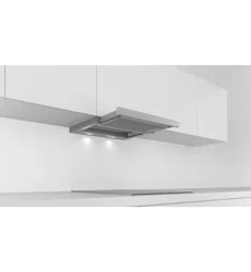
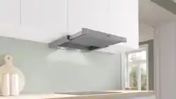
This appliance is installed in a upper cabinet.
Follow the enclosed installation instructions for additional special accessories (e.g. for circulating-air mode).
The surfaces of the appliance are sensitive. Avoid damaging them during installation.
General information
Exhaust air mode
Warning Risk of death!
Risk of poisoning from flue gases that are drawn back in. The exhaust air must not be conveyed into a functioning smoke or exhaust gas flue or into a shaft which is used to ventilate installation rooms that contain heating appliances. If the exhaust air is to be conveyed into a non-functioning smoke or exhaust gas flue, you must obtain the consent of the heating engineer responsible.
If the exhaust air is conveyed through the outer wall, a telescopic wall box should be used.
Exhaust duct
Note: The appliance manufacturer does not provide any warranty for faults attributable to the pipe section.
The appliance achieves its optimum performance by means of a short, straight exhaust air pipe and as large a pipe diameter as possible.
As a result of long, rough exhaust air pipes, many pipe bends or pipe diameters that are smaller than 150 mm, the optimum extraction performance is not achieved and fan noise is increased.
The pipes or hoses for laying the exhaust air line must consist of non-combustible material.
Round pipes
An inner diameter of 150 mm, but at least 120 mm, is
recommended.
Flat ducts
The inner cross-section must correspond to the
diameter of the round pipes.
150 mm diameter, approx. 177 cm2
120 mm diameter, approx. 113 cm2
Flat ducts should not have any sharp deflections.
Use sealing strips for different pipe diameters.
Preparing the units
The fitted unit must be level and have sufficient loadbearing capacity.
The max. weight of the extractor hood is 18 kg.
Appliance dimensions and safety clearances
Observe the appliance's dimensions.
Comply with the safety clearances.
If the installation instructions for the gas cooking appliances specify a different distance, the largest distance must always be provided for.
The fitted unit must be heat-resistant up to 90 °C.The fitted unit must still be sturdy after the cut-outs have been made.
To install the extractor hood in a wall-hanging cupboard, the extractor hood must be provided with the following dimensions:
1. Make the cut-out for the exhaust air pipe. To do this, make an opening in the top or back panel of the fitted unit with an additional recess for the power cord.
2. If the cabinet base is in place, remove it. Mark the fastening points on the inside of the cabinet and use a bradawl to make indentations where the holes are to be. To help you mark the fastening points, use the fastening piece provided.
Body wall thickness: 16 mm
1. Screw the mounting pieces to the body on the left and right. A
2. Remove the tabs from the bottom of the mounting pieces. B
Body wall thickness: 19 mm
1. Fold out the tabs on both of the mounting pieces. A
2. Screw the mounting pieces to the body on the left and right. B
3. Remove the tabs from the bottom of the mounting pieces. C
Preparing the appliance
A handle strip must be screwed to the filter pull-out. This handle strip can be one that is provided with the appliance, or one that is available as an accessory.
1. Use the screws provided to secure the handle strip to the filter pull-out.
2. Connect the power cord provided to the appliance.A
3. Use the strain relief to secure the power cord in place.B
Installation
Sliding the appliance up into place
1. Slide the appliance up into place and make sure it is positioned correctly. A
2. Measure the distance between the appliance and the wall, and mark this on the filler strip.
3. If required, shorten the filler strip to the required dimension. B
Sliding out the appliance
Note: Before you remove the appliance, protect the hob with a piece of polystyrene from the packaging.
1. Use a flat-blade screwdriver to push in the fastening bolt, and turn it 90° until it locks into place. A
2. Push in the fastening bolt gently with your fingers, and turn it until it comes out of the housing along with the spring.B
Pull gently on the fastening bolt; before you do this, take hold of the appliance from beneath with the other hand. C
3. Carefully remove the appliance.
4. Screw in the filler strip fully.
5. Push in the fastening bolt and turn it 90°.
Final fitting stage
1. Slide the appliance up into place. A
2. Lock the fastening bolts on the left and right. B
3.Fit the protective caps on the left and right. C
4. Establish the electrical connection.
Note: The extractor hood's housing can be concealed within the upper cabinet. In doing so, you must observe the following:
The intermediate floor must not be placed on the extractor hood's housing.
The front panel must not be secured to the housing.
Access must be available in order to change the filter and for the after-sales service.
Appliance width 90 cm: You must also screw the appliance to the wall-hanging cupboards either side of it.
Changing the filter pull-out's limit stop
On some versions of the appliance, the limit stop for the filter pull-out can be changed. Spacers are included with these appliances in order to position the appliance's handle strip flush with the fitted unit.
1. Pull the filter pull-out towards you.
2. Shorten the spacer to the required dimension and insert it into the slot specified.
Connecting the pipes
Note: If an aluminium pipe is used, smooth the area where it is to be connected before you connect it.
Exhaust air pipe, dia. 150 mm (recommended size)
Fit the exhaust air pipe directly to the air-pipe connector and seal the joint.
Exhaust air pipe, dia. 120 m
Fit the reducing connector directly to the air-pipe connector.
Attach the exhaust air pipe to the reducing connector.
Seal both joints appropriately.
Removing the appliance
Disconnect the electrical connection.
Disconnect the pipes.
Remove the metal grease filter.
Remove the protective caps from the fastening elements.
Remove the appliance; see section entitled "Removing the appliance".
 The air which is drawn in is cleaned by the grease filters and conveyed to the exterior by a pipe system.
 The air which is drawn in is cleaned by the grease filters and an activated carbon filter, and is conveyed back into the kitchen.
 button. The fan starts at setting 2.
 button.