Loading ...
Loading ...
Loading ...
8 9
A. “TIMER/CLEAN” buon
Press this button to enter the TIMER setting program. Press and hold this button for more than 5 seconds to enter
the CLEAN program.
B. “ON/OFF” buon
Press this button to enter STANDBY mode. During Self-cleaning or Ice making program, press this button to turn
off the appliance. If the appliance is set with Timer, press this button to cancel the Timer setting.
When the appliance is making ice cubes, press and hold this button for more than 5 seconds to switch to the
ice collecting process.
C. LCD display
1. Environmental temperature and ice making time countdown. Unit of Ice making time countdown is Minutes (M).
Unit of environmental temperature is Fahrenheit (F).
2. Ice making and ice-collecting display. The rotation of the symbol indicates the process of ice making, while
the ash of the symbol indicates the process of ice-collecting.
3. Automatic self-cleaning.
4. On/Off status.
5. Error code display. E1 means the environmental temperature sensor is damaged. E2 means there is an ice making
error or refrigerant leak.
6. Water inow and shortage display. When the symbol ashes, it indicates that there is enough water in the water tank.
When the symbol lights on, it indicates that there is not enough water in the water tank.
7. Ice full alarm. Take out the ice before the next ice making cycle.
8. Setting display. Unit for time switch machine is Hour (H). Unit for the ice making time is Minute (M).
D&E. “+” “-” buon
Adjust the ice making time length with the “+” or “-” button. The default setting is zero. There will be 1 minute added
or reduced per each press of the “+” or “-” button.
It is also used to adjust the delay time of the timer. The default setting is zero. There will be 1 hour added or
reduced per each press of the “+” or “-” button.
CONTROL PANEL & FUNCTIONS
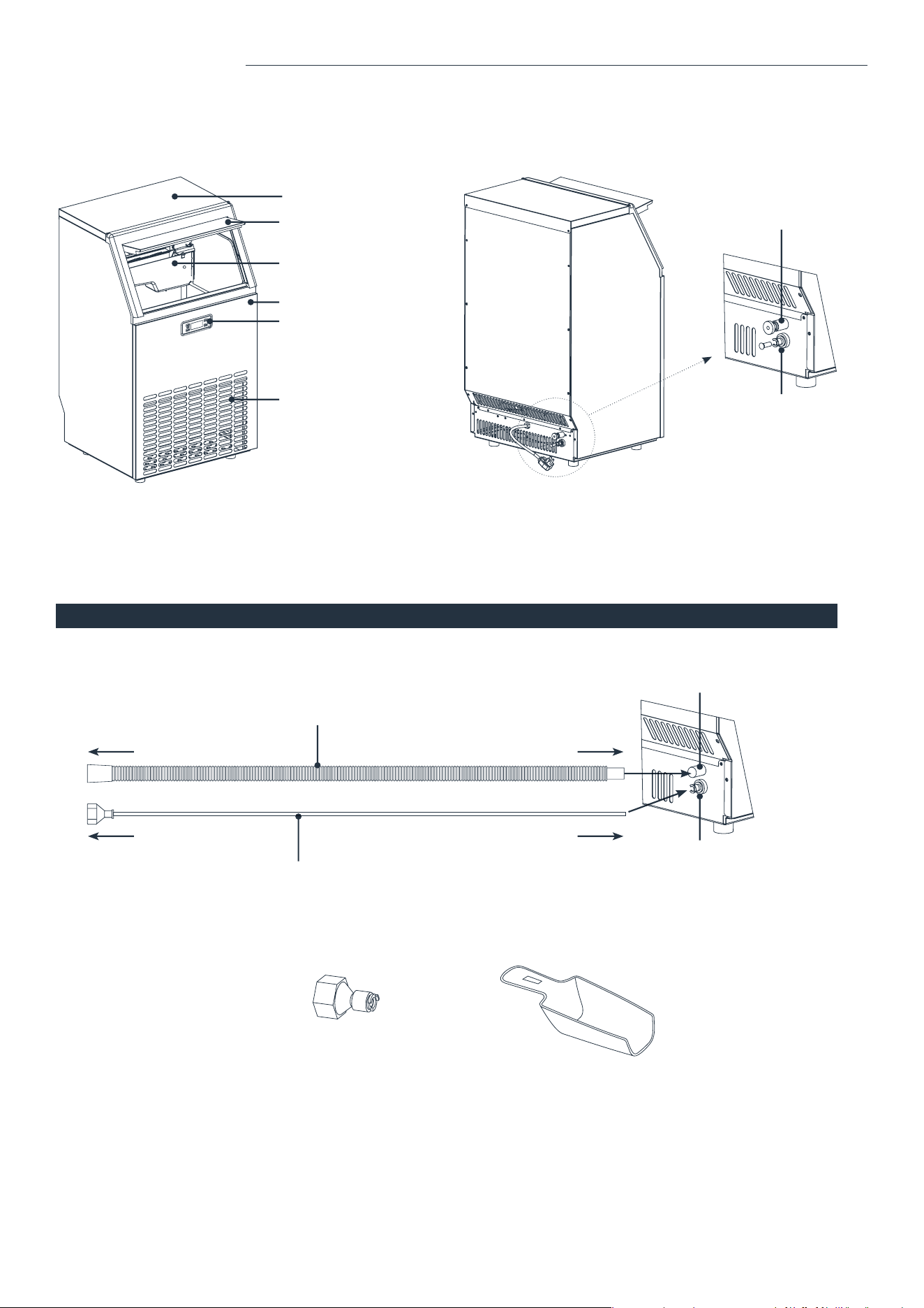
ACCESSORIES
Water draining hose (length: 6.5 feet)
Water supply hose (Length: 9 feet, Diameter: 0.25 inches)
Top cover
Ice bin door
Ice making & water tank assembly
Front panel
Control panel
Air outlet
Water supply hose port
(to be connected to the water supply)
Water draining hose port
PARTS DESCRIPTION PARTS DESCRIPTION
Water supply hose port
(to be connected to the water
supply hose and water supply)
Drain hose port
To water supply To water supply hose port
To drain To drain hose port
A E
B D
C
1
8
2
7
3
6
4
5
Water supply connector Ice Scoop
NOTE: Keep drain
hose below water
drain hose port.
Loading ...
Loading ...
Loading ...