GE is a trademark of the General Electric Company. Manufactured under trademark license.
OWNER’S MANUAL
AIR CONDITIONER
RV
49-5000406 Rev. 0 07-19 GEA
SAFETY INFORMATION .........3
INSTALLATION INSTRUCTIONS
Before You Begin ......................4
Tools You will Need ....................4
RARMN1A Parts List ....................5
RARAED1A Parts List ...................6
RAREN1A Parts List ....................7
Roof Requirements ....................8
Roof Requirements and Prep ............9
Electrical Requirements ................9
Placing Unit on Roof ...................9
Installing Unit ........................10
Electrical Control Installation ........... 11
USING THE AIR CONDITIONER
Controls .............................12
Air Direction .........................13
Normal Operating Sounds .............13
CARE AND CLEANING
Indoor Panel .........................14
Air Filter .............................14
Annual Maintenance ...................14
TROUBLESHOOTING ............15
LIMITED WARRANTY ...........17
CONSUMER SUPPORT ..........18
ARC13AACWK1
ARC13AACBK1
ARC15AACWK1
ARC15AACBK1
ARH15AACWK1
ARH15AACBK1
ENGLISH
Write the model and serial numbers
here:
Model # _______________
Serial # _______________
You can find them on a label on the
air conditioner.

2 49-5000406 Rev. 0
THANK YOU FOR MAKING GE APPLIANCES A PART OF YOUR RV
Whether you grew up with GE Appliances, or this is your first, we’re happy to have you in the family.
We take pride in the craftsmanship, innovation and design that goes into every GE Appliances
product, and we think you will too. Among other things, registration of your appliance ensures that we
can deliver important product information and warranty details when you need them.
Register your GE appliance now online. Helpful websites and phone numbers are available in the
Consumer Support section of this Owner’s Manual.

49-5000406 Rev. 0 3
SAFETY INFORMATION
IMPORTANT SAFETY INFORMATION
READ ALL INSTRUCTIONS BEFORE USING THE APPLIANCE
For your safety, the information in this manual must be followed to minimize the risk of
fire, electric shock or personal injury.
Ŷ8VHWKLVDSSOLDQFHRQO\IRULWVLQWHQGHGSXUSRVHDV
described in this Owner’s Manual.
ŶThis air conditioner must be properly installed in accordance
with the Installation Instructions before it is used.
ŶReplace immediately all electric service cords that
have become frayed or otherwise damaged. .
ŶTurn the unit OFF and disconnect all power to the
vehicle before cleaning and servicing.
ŶTo avoid risk of injury or property damage, the air
conditioner should only be serviced by a qualified
servicer, who should hold a current valid certificate
from an industry-accedited assessment authority,
which authorizes their competence to handle
refrigerants safely in accordance with an industry
recognized assessment specification.
ŶFor your safety…do not store or use combustible
materials, gasoline or other flammable vapors or
liquids in the vicinity of this or any other appliance.
ŶAll air conditioners contain refrigerants, which under federal
law must be removed prior to product disposal. If you are
getting rid of an old product with refrigerants, check with
the company handling disposal about what to do.
ŶThese R410A air conditioning systems require
contractors and technicians to use tools, equipment
and safety standards approved for use with this
refrigerant. DO NOT use equipment certified for R22
refrigerant only.
WARNING
READ AND SAVE THESE INSTRUCTIONS
4 49-5000406 Rev. 0
Installation Instructions
BEFORE YOU BEGIN
Read these instructions completely and carefully.
•
Save these instructions for local inspector’s use.
•
Observe all governing codes and ordinances.
• Note to Installer – Be sure to leave these
instructions with the Consumer.
• Note to Consumer – Keep these instructions for
future reference.
• Skill level – Installation of this appliance requires a
qualified RV technician.
• Completion time – Approximately 1 hour
• We recommend that two people install this product.
• Proper installation is the responsibility of the
installer.
• Product failure due to improper installation is not
covered under the Warranty.
<RX0867XVHDOOVXSSOLHGSDUWVDQGXVHSURSHU
installation procedures as described in these
instructions when installing this air conditioner.
Questions? Call 1-877-540-7837 or Visit our Website at: GEAppliances.com
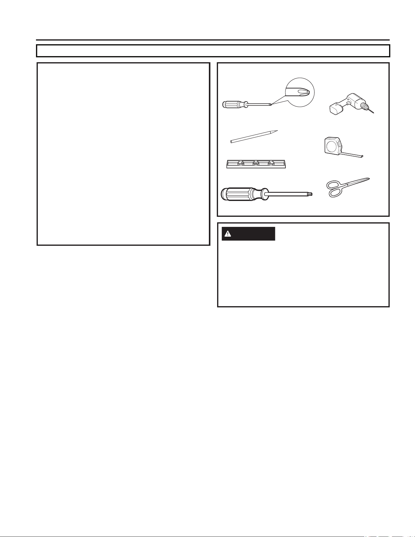
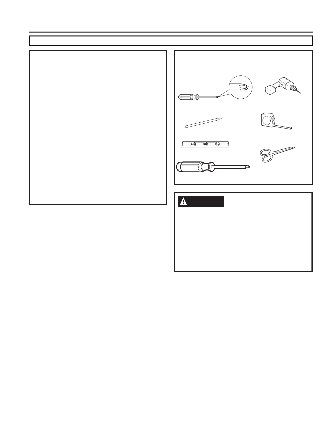
TOOLS YOU WILL NEED
Phillips head screwdriver
Ruler or tape measure
Pencil
Level
Scissors or knife
Torque Wrench (0-60 in-lbs)
Drill and 1/8” drill bit
CAUTION
Be cautious of sharp edges, as they may cause
injury. When lifting the air conditioner, use 2 people
to lift.
Electrical wiring may be present between roof and
ceiling. Be sure that power is disconnected at the
mains and battery. Be sure that gas supply is shut off.
Failure to do so may result in injury or death.
INSTALLATION INSTRUCTIONS
49-5000406 Rev. 0 5
INSTALLATION INSTRUCTIONS
Installation Instructions
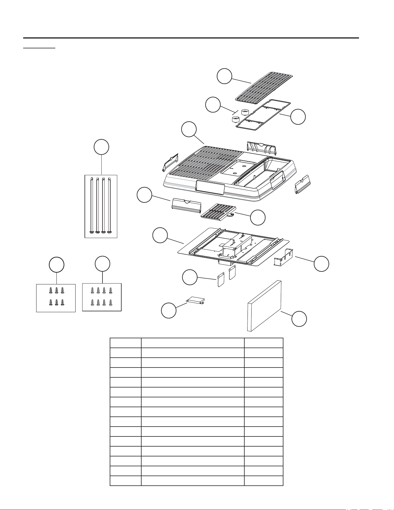
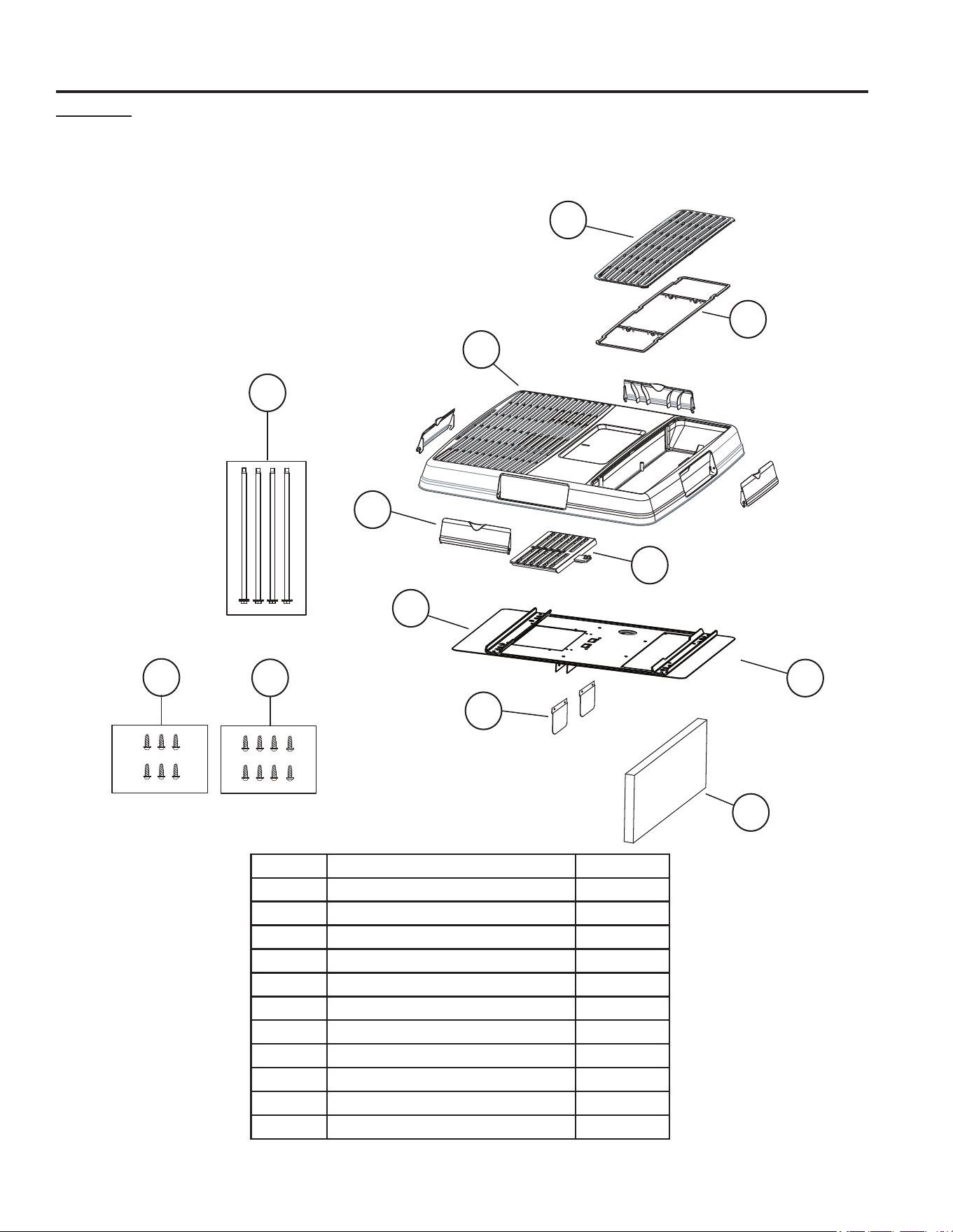
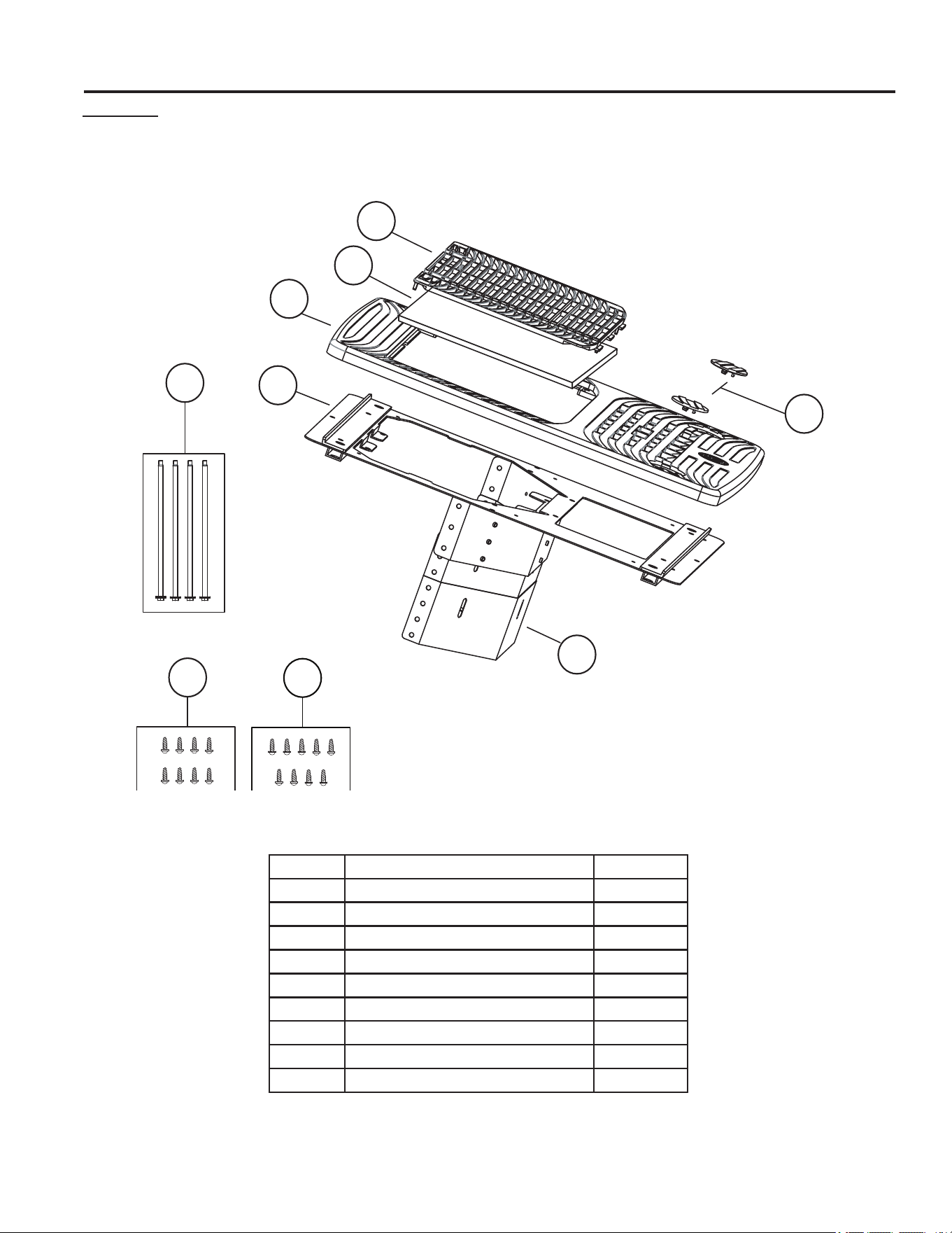
RARMN1A
Check the contents of the accessories supplied with your air conditioner as shown below:
Number Part Name QTY.
1 Filter Retainer 1
2 Filter 1
3 Knobs 2
4 Ceiling Panel 1
5 Side Discharge Ports 4
6 Direct Discharge Guide 1
7 Mounting template 1
8 Junction Box Cover 1
9 Connection Shield 1
10 Air division baffle 1
11 M8 Mounting Bolts 4
12 Wood screws 8
13 Baffle retainer plates 2
14 Sheet metal screws 6
1
2
3
4
5
6
7
8
9
10
11
12
13
14
6 49-5000406 Rev. 0
Installation Instructions
INSTALLATION INSTRUCTIONS
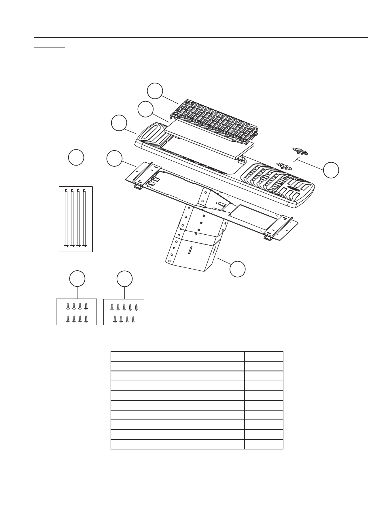
Number Part Name QTY.
1 Filter Retainer 1
2 Filter 1
3 Screw Cover 2
4 Ceiling Panel 1
5 Mounting template 1
6 Air division baffle 1
7 M8 Mounting Bolts 4
8 Mounting screws 8
9 Sheet metal screws 9
1
2
3
4
5
6
7
8
9
RARED1A
Check the contents of the accessories supplied with your air conditioner as shown below:
49-5000406 Rev. 0 7
Installation Instructions
INSTALLATION INSTRUCTIONS
Number Part Name QTY.
1 Filter Retainer 1
2 Filter 1
3 Ceiling Panel 1
4 Side Discharge Ports 4
5 Direct Discharge Guide 1
6 Mounting template 1
7 Air division baffle 1
8 M8 Mounting Bolts 4
9 Wood screws 8
10 Baffle retainer plates 2
11 Sheet metal screws 6
1
2
3
4
5
6
9
7
8
9
10
11
RAREN1A
Check the contents of the accessories supplied with your air conditioner as shown below:
8 49-5000406 Rev. 0
INSTALLATION INSTRUCTIONS
Installation Instructions
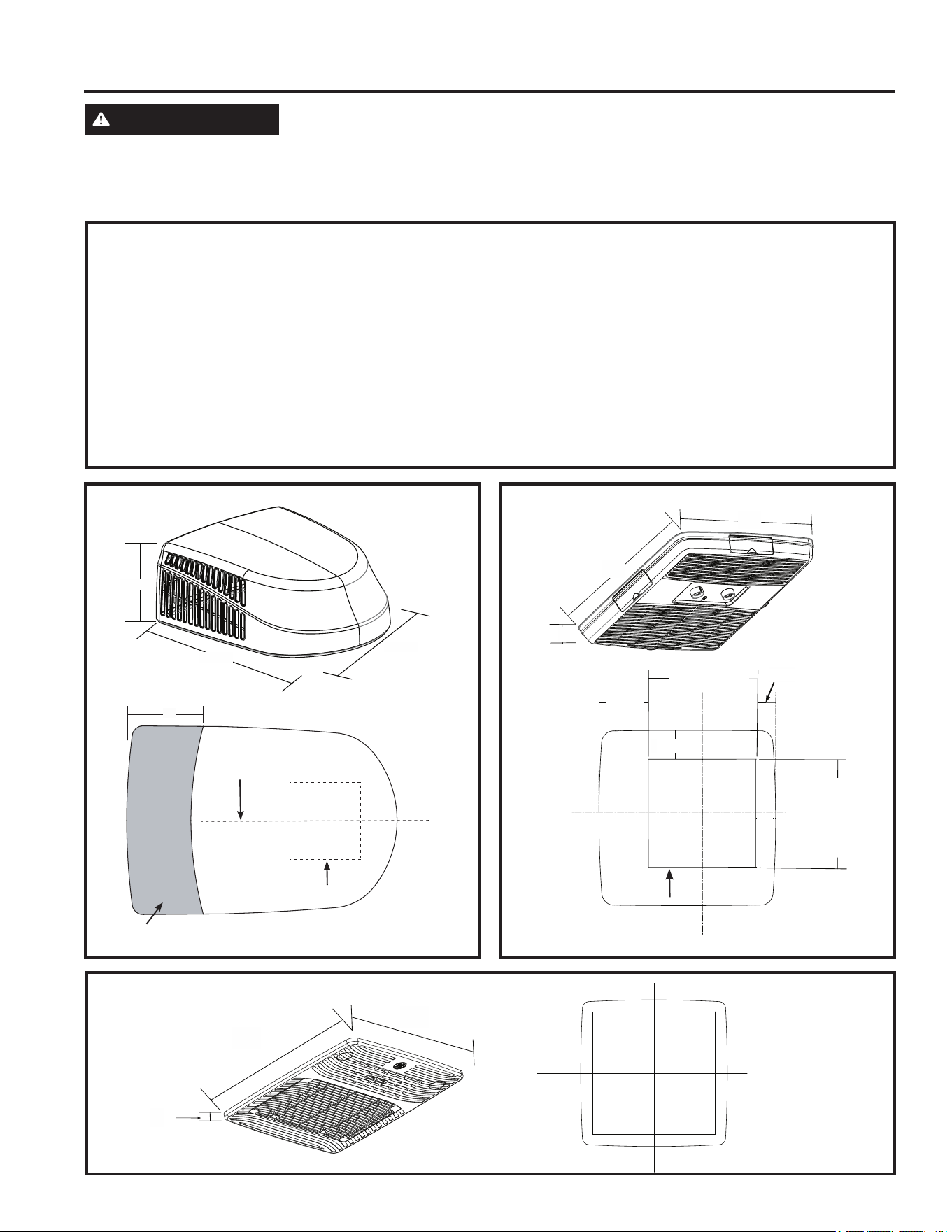
A. ROOF REQUIREMENTS AND DETERMINING LOCATION FOR INSTALLATION
Air conditioners covered in this manual are designed
for installation on an RV’s roof.
Installation of this air conditioner must be in accordance
with NFPA 1192 and NFPA 70.
For proper installation, there must be a 14- 1/4” x
14-1/4” (+-1/8”) square opening in the roof and ceiling
of the RV.
There must be 2 to 6 inches between the RV ceiling
and roof.
Air conditioners covered in this manual are designed fit
over preexisting roof vent openings.
If a roof vent opening isn’t available, use the following
guidelines:
8QLWLVWREHLQVWDOOHGFHQWHUHGVLGHWRVLGHRQWKH59URRI
8QLWLVWREHLQVWDOOHGRQDVHFWLRQRIURRIZKLFKLVOHYHOZLWK
respect to the RV roof if parked on a flat, level surface
.
Roof at the point of installation can have a maximum 15
degree tilt towards the front or rear of the RV.
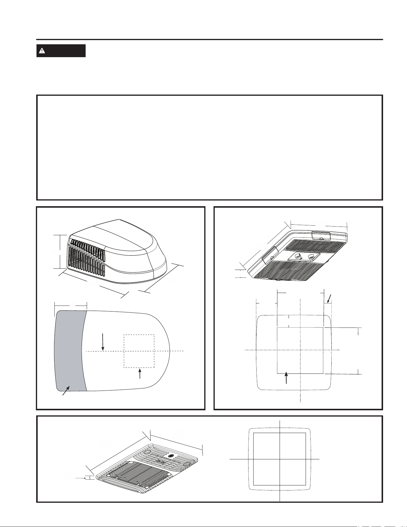
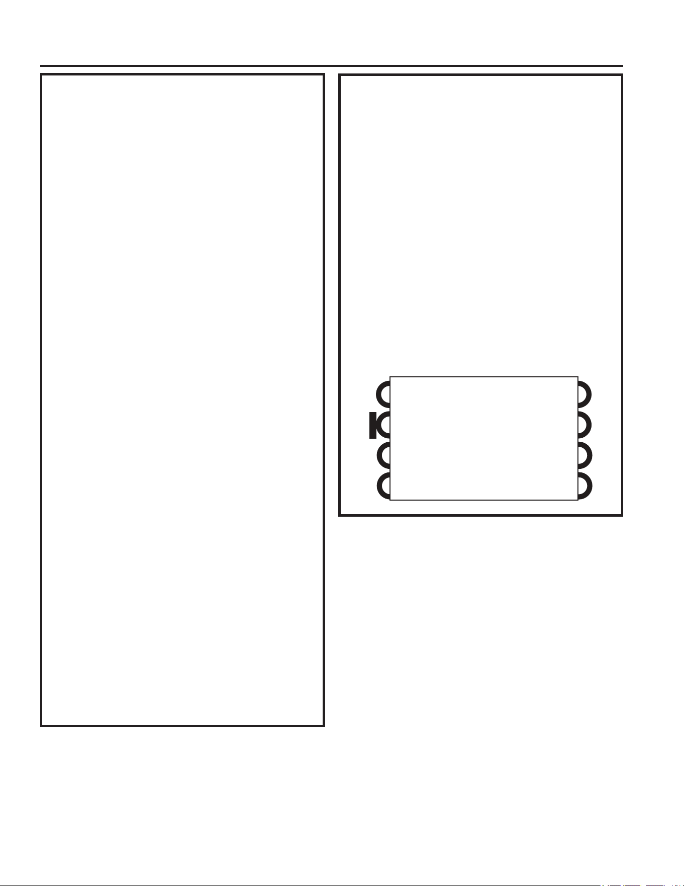
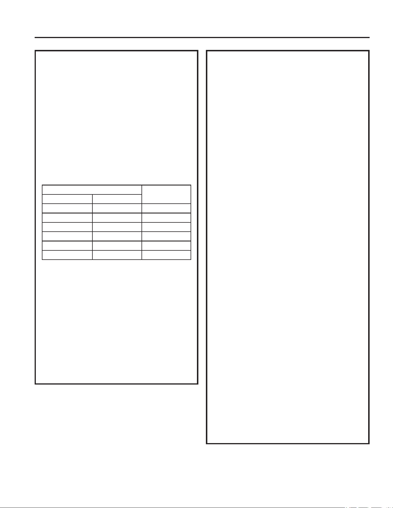
Figure 1: Outdoor unit:
Figure 2: Indoor unit.
Figure 3: Ducted Unit
Figure 1: Outdoor unit:
32 - 7/8”
27 - 7/8”
13 - 7/8”
Figure 2: Indoor unit:
23”
21”
3”
14.2520”
3.5”
14.2520”
6.5”
2.5”
Roof opening
18”
Center Line of unit
Keep at least 18” free of obstructions at rear of unit.
Roof opening
Front
WARNING
ELECTRICAL SHOCK HAZARD
Death or serious injury can result from failure to follow these instructions.
• Disconnect 120 VAC power supply before beginning installation and/or servicing
• Ensure product is properly grounded according to the applicable codes
• Replace all parts and panels before operating
Figure 3: Ducted unit:
16 1/2”
16 1/2”
5/8”
14 63/250
14 63/250
2 1/2
3 1/2
6 1/2
49-5000406 Rev. 0 9
Installation Instructions
C. ELECTRICAL REQUIREMENTS
These models require a 115-volt, 60-Hz protected with
a 20-amp time-delay fuse or circuit breaker.
8VHDPLQLPXPRIVKHDWKHG$:*FRSSHUZLUH
with ground.
Be sure that 16” of supply wire is passed through the
framing. This ensures enough wire is available for an
easy connection in the junction box.
B. ROOF REQUIREMENTS AND
PREPARATION
If a preexisting roof vent opening will be used:
8QVFUHZDQGUHPRYHURRIYHQWIURP59
2. Seal all holes and seams with a weather resistant
sealant.
3. Measure the width and length of the vent opening.
If the opening doesn’t comply with the requirements
above, it must be resized.
If a preexisting opening will not be used, a new opening
will be cut through both the roof and ceiling of the RV.
7KLVRSHQLQJ0867EHEHWZHHQVWUXFWXUDOURRI
members.
2. Do NOT cut structural roof members to create
opening for this air conditioner. Doing so may
cause damage to RV and air conditioner.
3. Do NOT create a low spot on the RV roof. Water
can pool and may leak through the opening.
The square opening must be boxed with framing
at least 3/4” thick to withstand the load from the
compression bolts.
Be sure to provide an access hole for RV wiring
toward the front of the 14 1/4 x 14 1/4” opening.
Roof and RV structure at point of install must be
strong enough to support air conditioner without any
deflection. Deflection will allow water to pool at the air
conditioner’s gasket, which may cause a leak.
D. PLACING UNIT ON ROOF
CAUTION
LIFTING HAZARD. Ensure proper
lifting methods and controls are
used when lifting unit to the RV roof. Failure to do so
can result in injury.
1. Remove unit from packaging and dispose of
packaging.
2. Do not slide the unit on its mounting gasket.
'DPDJHWRJDVNHWFDQFDXVHDOHDN8VLQJWZR
people, lift the unit and place over the prepared
opening. The front of the unit must face the RV’s
direction of travel. Damage to condenser fan and
coil will occur if this instruction is not followed.
WARNING
It is important that these installation
instructions are read and understood before
installation and use.
Failure to securely install the unit to the RV before
moving the RV may result in personal injury or death.
Do not operate the unit or recreational vehicle until the
unit is fully secured on roof.
3. Bring the ceiling assembly with all provided
mounting hardware into the RV. All work on the
exterior of the RV is now complete.
INSTALLATION INSTRUCTIONS
10 49-5000406 Rev. 0
E. MECHANICAL CONTROL
INSTALLATION
1. From inside the RV, double check the gasket’s
position and alignment above the roof opening.
Adjust if necessary. The air conditioner can be
moved and adjusted by pushing upwards from
inside the RV.
2. Reach through the base pan and pull the electrical
power cord from the air conditioner through the
ceiling opening.
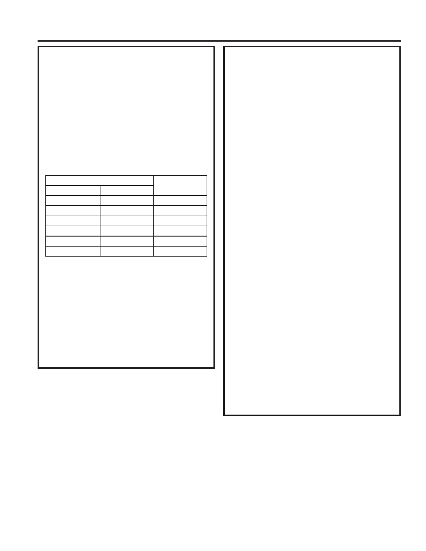
3. Measure ceiling to roof thickness.
4. Cut rows from the bottom of the foam baffle
according the table below:
Ceiling to roof thickness Rows to cut
Minimum Maximum
22.510
2.5 3 8
3.5 4 6
4.5 5 4
55.52
5.5 6 0
Best Practice:
Cut away one row at a time, and check installation
position of baffle. With the top foam compressed onto
the air conditioner’s base pan, the bottom of the baffle
should be flush to the ceiling opening.
5. Install 2 baffle retainer plates onto the ceiling
assembly
8QVFUHZDQGUHPRYHSLQFRQQHFWLRQFRYHUIURP
the ceiling assembly.
7. Plug 6 pin connector from the roof mounted air
conditioner into the electronic control box.
E. MECHANICAL CONTROL
INSTALLATION
(cont.)
8. Reassemble the 6 pin connection cover to the
ceiling assembly.
9. Route the 115 VAC power cord through the strain
relief of the ceiling assembly. Tighten the strain
relief, making sure not to damage the wires.
10. Place foam baffle into position between 2 retainer
plates.
11. Push the ceiling assembly into the roof opening,
and begin hand-threading each of the 4 mounting
bolts through the nuts in the base pan.
12. Tighten the 4 bolts evenly to 45 +- 5 inch pounds
using a torque at least rated for 0-60 in-lbs. Even
compression is required to prevent leaks through
the gasket.
13. Remove junction box cover.
8VLQJSURYLGHGZLUHFRQQHFWRUVFRQQHFWEODFNWR
black, white to white, and ground to green.
8VLQJHOHFWULFDOWDSHVHFXUHWKHFRQQHFWRUVWR
prevent any potential movement due to vehicle
vibration.
16. Push wires and connections into the junction box.
Reinstall junction box cover.
17. Align plastic ceiling panel to the metal assembly.
18. Install the 2 provided sheet metal screws to attach
the plastic panel to the metal assembly. The filter
must be removed to install these screws.
19. Install the 8 provided wood screws to secure the
plastic panel to the RV ceiling. The air discharge
doors should not be installed, or these screws will
be difficult to drive.
20. Assemble the filter and air discharge doors to the
plastic panel.
21. Install the 2 control knobs.
22. Installation is complete. Refer to “Controls” on
page 12 before attempting to operate the air
conditioner.
Installation Instructions
INSTALLATION INSTRUCTIONS
49-5000406 Rev. 0 11
INSTALLATION INSTRUCTIONS
Installation Instructions
F. ELECTRICAL CONTROL INST.
1. From inside the RV, double check the gasket’s
position and alignment above the roof opening.
Adjust if necessary. The air conditioner can be
moved and adjusted by pushing upwards from
inside the RV.
2. Reach through the base pan and pull the electrical
power cord from the air conditioner through the
ceiling opening.
3. Push the ceiling mounting template into the roof
opening and begin hand-threading each of the 4
mounting bolts through the nuts in the base pan.
4. Tighten the 4 bolts evenly to 45±5 inch pounds
using a torque at least rated for 0-60 in-lbs. Even
compression is required to prevent leaks through
the gasket.
5. Place dividing baffle into position on the ceiling
assembly. Ensure baffle is pressed against the
base pan, forming an airtight seal.
6. Mount the dividing baffle to the mounting template
using three screws.
7. Mount the dividing baffle to the framing timber
using two screws, creating an airtight seal.
8. Mount main control box to the mounting template
using four screws.
9. Remove two screws from main control box,
allowing the bottom section to hinge open. Control
board is now visible and accessible.
10. Route the 115 VAC power cord through the strain
relief of the control box. Tighten the strain relief,
making sure not to damage the wires.
8VLQJSURYLGHGZLUHFRQQHFWRUVFRQQHFWEODFN
to black, white to white, and ground to green.
8VLQJHOHFWULFDOWDSHVHFXUHWKHFRQQHFWRUVWR
prevent any potential movement due to vehicle
vibration.
13. Route the 6 pin connector through opening of
the strain relief of the control box. Mate 6 pin
connector to the control box’s wire harness.
8VLQJSURYLGHGZLUHFRQQHFWRUVFRQQHFWIXUQDFH
wires (blue), 3 thermostat wires (red, yellow,
black), and two 12 VDC battery wires (red and
black).
F. ELECTRICAL CONTROL INST.(cont.)
15. Rotate lower section of control box upwards,
making sure not to crush any wires. Drive two
screws, securing the control box closed.
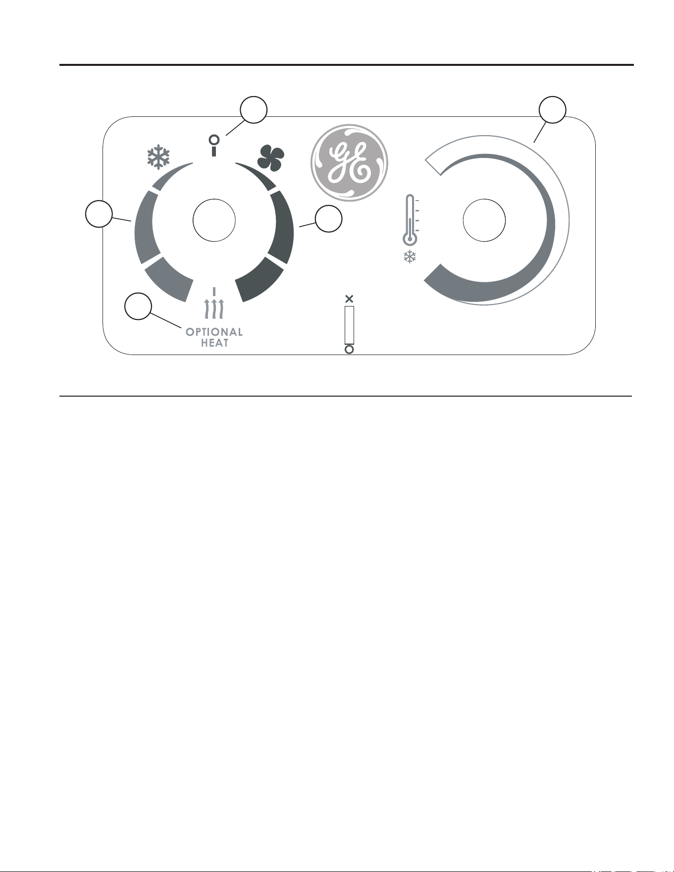
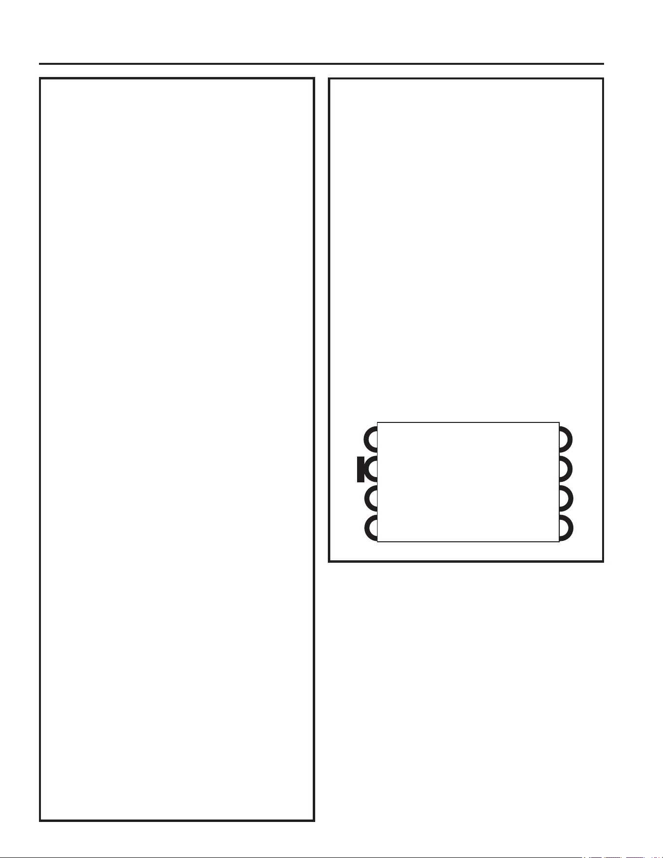
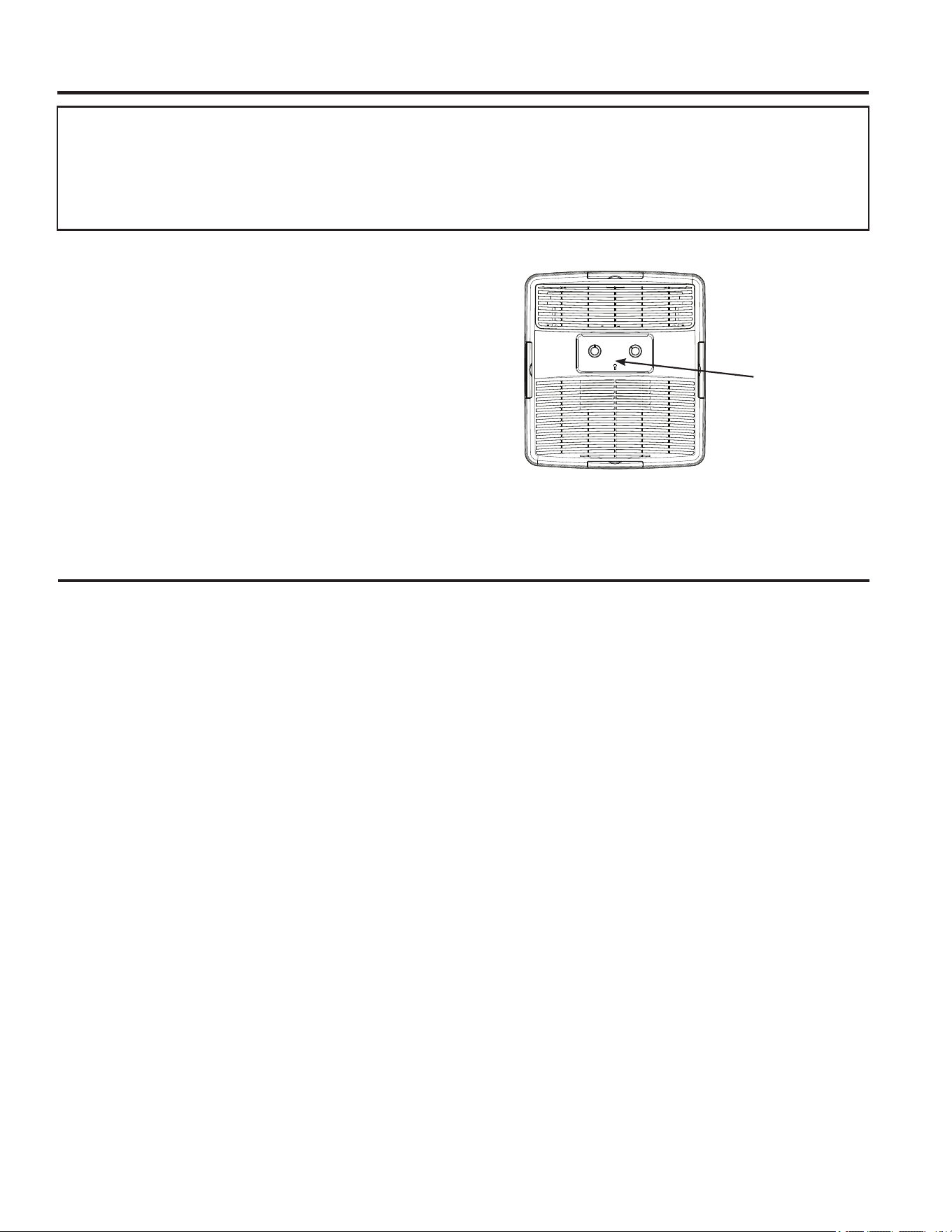
16. Grasp indoor coil temperature sensor, which is
hanging out of the control box. Reach up through
the mounting template and base pan to install the
sensor into the evaporator coil thermistor well (see
figure below).
17. Align plastic ceiling panel to the metal assembly.
18. Install the 6 provided sheet metal screws to attach
the plastic panel to the metal assembly. The
filter and screw covers must be removed to install
these screws.
19. Assemble the filter and screw covers to the plastic
panel.
20. Installation is complete. Refer to thermostat
operating instructions before attempting to
operate.
Thermistor Well
12 49-5000406 Rev. 0
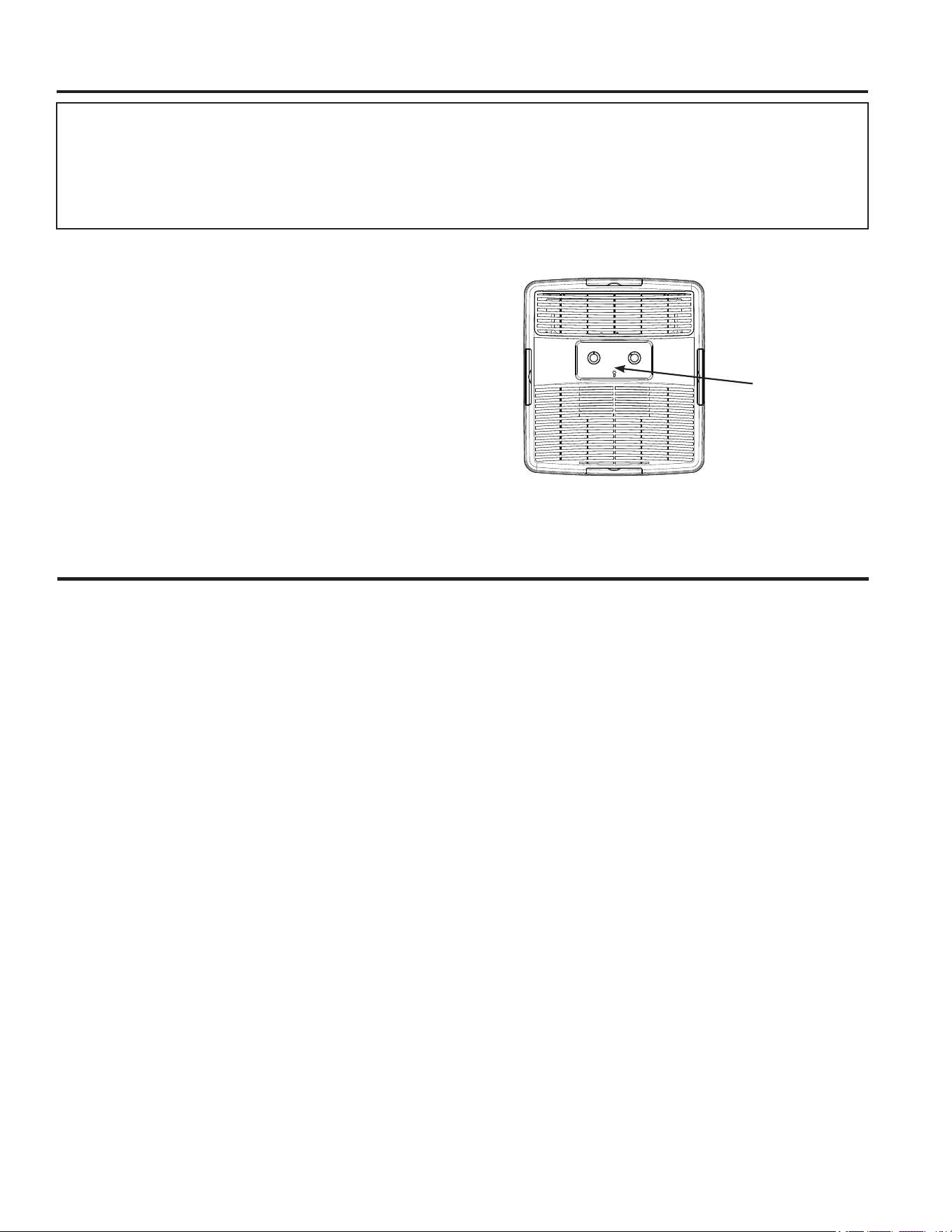
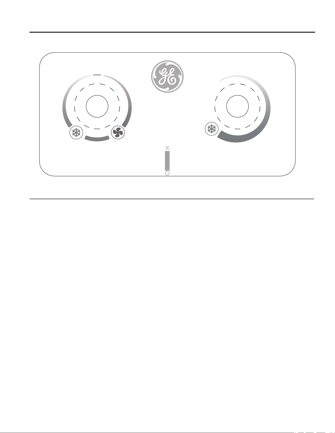
Controls
Controls
1. Power Off
The air conditioner is off in this position.
2. Air Conditioning Modes
In these positions, the compressor and fans will run
to provide cold air. The three modes correspond to
low, medium, and high fan speeds.
3. Fan Only Modes
In these modes, the fans will run to circulate air
in the RV. The three modes correspond to low,
medium, and high fan speeds.
4. Optional Heater
In this position, the optional heater will turn on, and
the fan will operate at low speed.
5. Temperature Selection
This knob determines the room set point
temperature. Turn this knob to increase or decrease
how cold the air conditioner will make the room.
Features and appearance will vary.
Air Conditioner Controls
1
2
3
4
5
USING THE AIR CONDITIONER
49-5000406 Rev. 0 13
USING THE AIR CONDITIONER
Using the Air Conditioner
IMPORTANT:
• When you turn off the air conditioner, wait at least 3
minutes before turning it back on. This prevents the
compressor from overloading. This 3 minute delay
also applies when switching from cool mode to fan
and back.
• Do not operate your air conditioner in the Cool mode
when the outside temperature is below 61°F (16° C).
The inside evaporator coil will freeze up, and the air
conditioner will not operate properly.
Air Direction
8VHWKHOHYHUWRRSHQRUFORVHYHQWRQIDFHRIFRQWURO
panel.
Open or close 4 side ports to adjust airflow from the air
conditioner.
Front View
Lever is located
between the two
knobs
Normal Operating Sounds
When your air conditioner is operating normally, you may hear sounds such as:
Ŷ'URSOHWVRIZDWHUKLWWLQJWKHFRQGHQVHUFDXVLQJDSLQJLQJRUFOLFNLQJVRXQG7KHZDWHUGURSOHWVKHOSFRROWKH
condenser.
Ŷ$LUPRYHPHQWIURPWKHIDQ
Ŷ&OLFNVIURPWKHWKHUPRVWDWF\FOH
Ŷ$KLJKSLWFKHGKXPRUSXOVDWLQJQRLVHFDXVHGE\WKHFRPSUHVVRUF\FOLQJRQDQGRII
14 49-5000406 Rev. 0
CARE AND CLEANING
Care and Cleaning
Indoor Panel
Turn the air conditioner off and disconnect power from the
air conditioner before cleaning.
To clean, use water and a mild detergent. Do not use
bleach or abrasives.
Annual Maintenance
Your air conditioner needs annual maintenance to help
ensure steady, top performance throughout the year.
Call your local authorized dealer to schedule an annual
checkup. The expense of an annual inspection is your
responsibility.
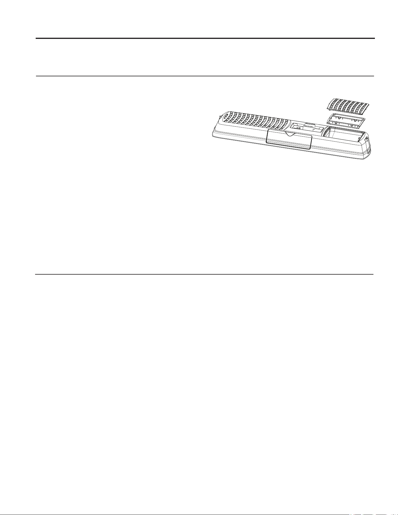
Air Filter
The air filter behind the front grille should be checked
and cleaned at least every 2 weeks and cleaned if
necessary.
DO NOT operate the air conditioner without a filter
because dirt and lint will clog it and reduce performance.
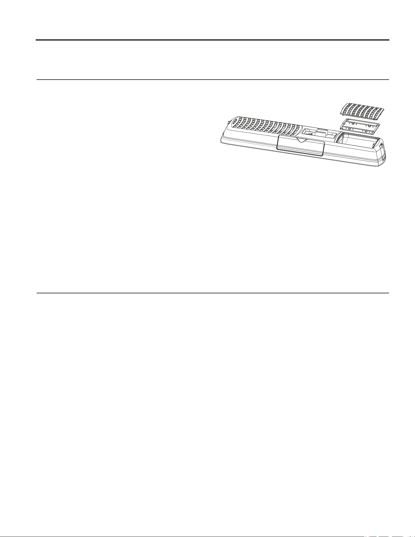
Cleaning the Air Filter
1. Turn off the air conditioner.
2. Remove the air filter and grill assembly by carefully
unsnapping the 6 tabs from the main panel. Then
separate the filter from the grill.
8VHDYDFXXPFOHDQHUWRFOHDQDLUILOWHU,IWKHDLU
filter is very dirty, wash it in warm water with a mild
detergent. Do not wash the air filter in the dishwasher
or use any chemical cleaners. Air dry the air filter
completely before replacing to ensure maximum
efficiency.
4. Reassemble the air filter to the grill.
5. Carefully reassemble the grill and filter assembly to
the main panel.
6. Turn on the air conditioner.
Cleaning the Front Panel
1. Turn off the air conditioner.
2. Clean the front panel with a soft, damp cloth.
3. Air dry the front panel completely.
4. Turn on the air conditioner.

49-5000406 Rev. 0 15
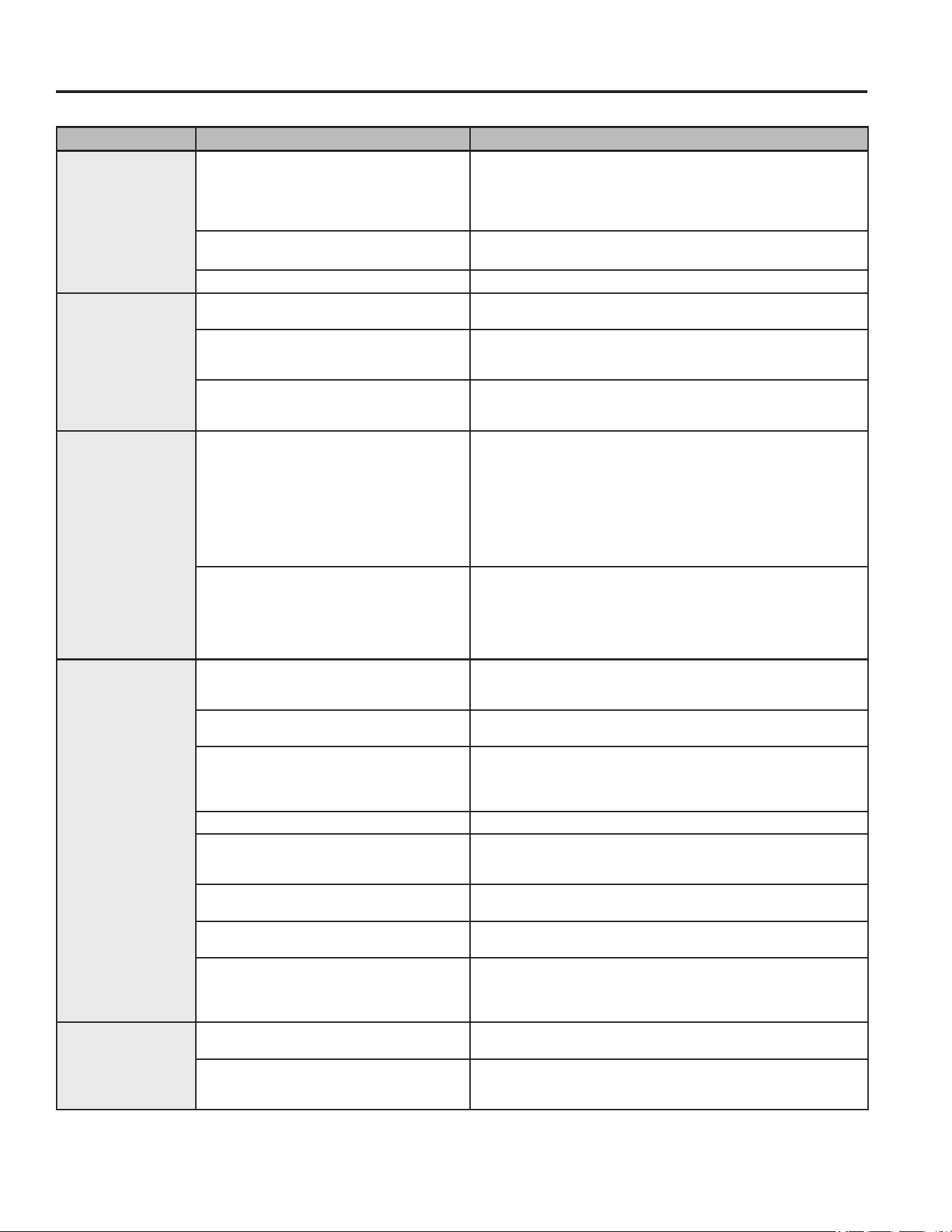
Troubleshooting Tips... Before you call for service
Save time and money! Review the charts on the following pages first and you may not need to call for service.
Problem Possible Cause What To Do
Air Conditioner
does not operate
A household fuse has blown, or
circuit breaker has tripped.
Replace the fuse or reset the circuit breaker. If the problem
continues, call an electrician. See “Electrical Requirements.”
The mode setting is in the OFF
position.
Press POWER or turn the Mode control to an active setting.
The local power has failed. Wait for power to be restored.
Air conditioner
blows fuses
or trips circuit
breakers
Too many appliances are being used
on the same circuit.
8QSOXJRUUHORFDWHDSSOLDQFHVWKDWVKDUHWKHVDPHFLUFXLW
Time-delay fuse or circuit breaker of
the wrong capacity is being used.
Replace with a time-delay fuse or circuit breaker of the
correct capacity. See “Electrical Requirements.”
You are trying to restart the air
conditioner too soon after turning off
the air conditioner.
Wait at least 3 minutes after turning off the air conditioner
before trying to restart the air conditioner.
Air conditioner
seems to run too
much
The current air conditioner replaced
an older model.
The use of more efficient components may cause the air
conditioner to run longer than an older model, but the total
energy consumption will be less. Newer air conditioners do
not emit the “blast” of cold air you may be accustomed to
from older air conditioners, but this is not an indication of
lesser cooling capacity or efficiency.
The air conditioner is in a heavily
occupied room, or heat-producing
appliances are in use in the room.
8VHH[KDXVWYHQWIDQVZKLOHFRRNLQJRUEDWKLQJDQGWU\QRW
to use heatproducing appliances during the hottest part of
the day. A higher capacity air conditioner may be required,
depending on the size of the room being cooled.
Air conditioner
cycles on and off
too much or does
not cool room in
cooling mode
The air conditioner is not properly
sized for your RV.
Check the cooling capabilities of your RV air conditioner.
The filter is dirty or obstructed by
debris.
Clean the filter.
There is excessive heat or moisture
(open container cooking, showers,
etc.) in the room.
8VHDIDQWRH[KDXVWKHDWRUPRLVWXUHIURPWKHURRP7U\QRW
to use heat-producing appliances during the hottest part of
the day.
The louvers or ducts are closed. Make sure louvers are open.
The outside temperature is below
60°F (15°C).
Do not try to operate your air conditioner in the cooling mode
when the outside temperature is below 65°F (18°C).
The temperature of the room you are
trying to cool is extremely hot.
Allow extra time for the air conditioner to cool off a very hot
room.
Windows or doors to the outside are
open.
Close all windows and doors.
The Temperature control is not at a
cool enough setting.
Adjust the TEMP control to a cooler setting by pressing the
minus button to reduce the temperature. Set the Fan Speed
control to the highest setting.
Water drips from
cabinet into your
house
The indoor coil may be frozen. De-ice by running the fan only until clear.
The air conditioner’s mounting gasket
may not be sealed against the roof.
Check mounting bolts and tighten to 45 ± 5 in-lbs if
necessary.
TROUBLESHOOTING

16 49-5000406 Rev. 0
NOTES
Notes
49-5000406 Rev. 0 17
LIMITED WARRANTY
GE Appliances Air Conditioner Limited Warranty
ŶImproper installation, delivery or maintenance. If you
have an installation problem, or if the air conditioner
is of improper cooling capacity for the intended use,
contact your dealer or installer. You are responsible
for providing adequate electrical connecting facilities.
ŶFailure of the product resulting from modifications
to the product or due to unreasonable use including
failure to provide reasonable and necessary
maintenance.
Ŷ/DERUQHFHVVDU\WRPRYHWKHXQLWWRDORFDWLRQZKHUH
it is accessible for service by an individual technician.
ŶReplacement of house fuses or resetting of circuit
breakers.
ŶDamage to the product caused by improper power
supply voltage, accident, fire, floods or acts of God.
ŶIncidental or consequential damage caused by
possible defects with this air conditioner.
ŶDamage caused after delivery.
What GE Appliances Will Not Cover:
This limited warranty is extended to the original purchaser and any succeeding owner for products purchased
IRU59XVHZLWKLQWKH86$DQG&DQDGD,IWKHSURGXFWLVORFDWHGLQDQDUHDZKHUHVHUYLFHE\DQDXWKRUL]HG59
servicer is not available, you may be required to bring the product to an authorized service location for service.
Authorized GE Service location for service.
Some states do not allow the exclusion or limitation of incidental or consequential damages. This limited warranty
gives you specific legal rights, and you may also have other rights which vary from state to state. To know what your
legal rights are, consult your local or state consumer affairs office or your state’s Attorney General.
Warrantor: GE Appliances, a Haier company
Louisville, KY 40225
All warranty service must be provided by certified RV Service Centers.
To schedule service call 1-877-540-7837
Have serial number and model number available when calling for service.
EXCLUSION OF IMPLIED WARRANTIES—Your sole and exclusive remedy is product repair as provided in this
Limited Warranty. Any implied warranties, including the implied warranties of merchantability or fitness for a
particular purpose, are limited to two years or the shortest period allowed by law.
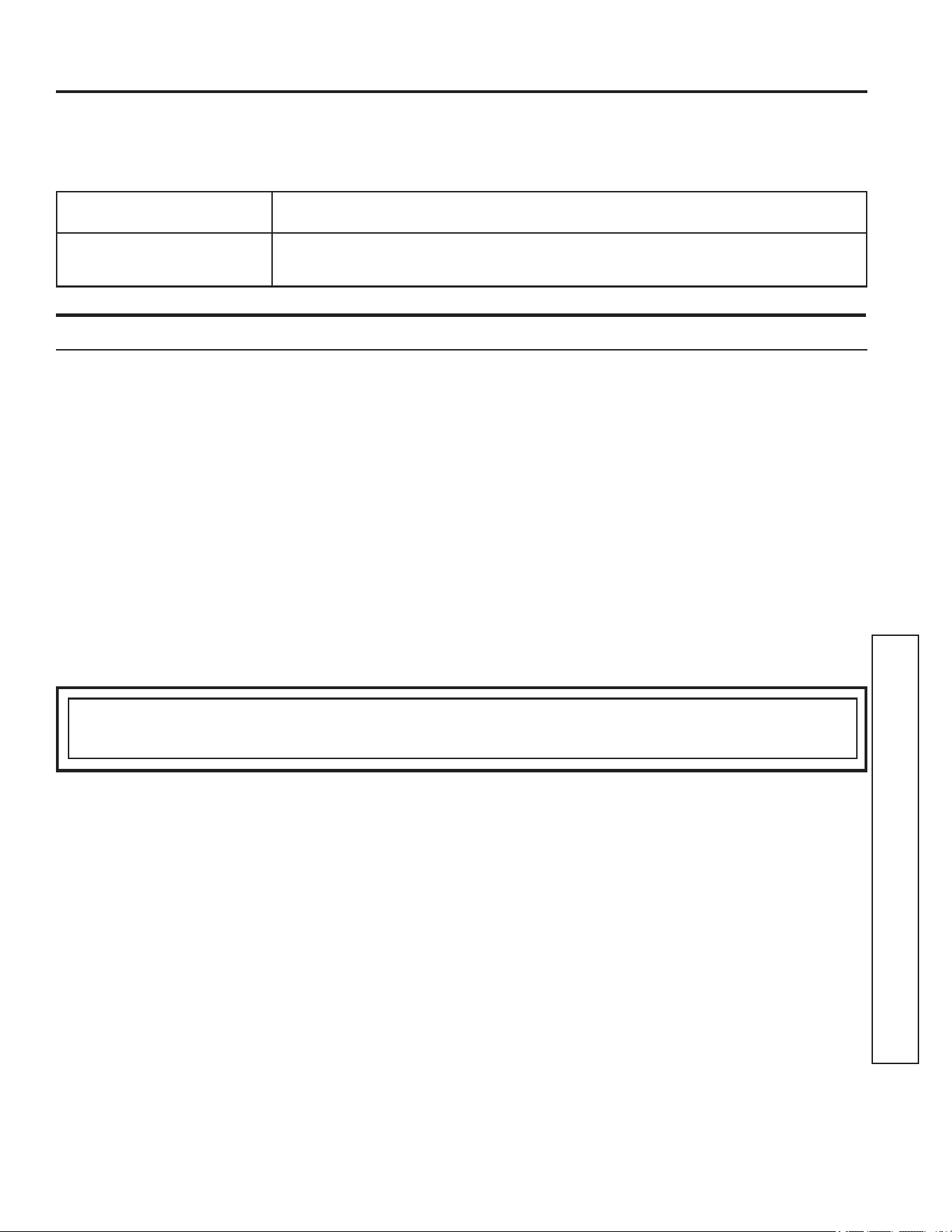
For The Period Of: GE Appliances Will Replace:
Two Years
From the date of the
original purchase
Any part of the air conditioner which fails due to a defect in materials or workmanship.
During this limited two-year warranty, GE Appliances will also cover all labor and
related service to replace the defective part.
Staple your receipt here. Proof of the original purchase
date is needed to obtain service under the warranty.

18 49-5000406 Rev. 0
Printed in China
Consumer Support
CONSUMER SUPPORT
GE Appliances Website
Have a question or need assistance with your appliance? Try the GE Appliances Website 24 hours a day, any day
of the year! You can also shop for more great GE Appliances products and take advantage of all our on-line support
VHUYLFHVGHVLJQHGIRU\RXUFRQYHQLHQFH,QWKH86GEAppliances.com
Register Your Appliance
Register your new appliance on-line at your convenience! Timely product registration will allow for enhanced
communication and prompt service under the terms of your warranty, should the need arise. You may also mail in
WKHSUHSULQWHGUHJLVWUDWLRQFDUGLQFOXGHGLQWKHSDFNLQJPDWHULDO,QWKH86GEAppliances.com/register
Schedule Service
Call 1-877-540-7837 during normal business hours.
Extended Warranties
Purchase a GE Appliances extended warranty and learn about special discounts that are available while your
warranty is still in effect. You can purchase it on-line anytime. GE Appliances Services will still be there after your
ZDUUDQW\H[SLUHV,QWKH86GEAppliances.com/extended-warranty or call 800.626.2224 during normal
business hours.
Remote Connectivity
For assistance with wireless network connectivity (for models with remote enable),
visit our website at GEAppliances.com/connected-home-smart-appliancesRUFDOOLQWKH86
Parts and Accessories
Individuals qualified to service their own appliances can have parts or accessories sent directly to their homes
(VISA, MasterCard and Discover cards are accepted). Order on-line today 24 hours every day.
,QWKH86GEApplianceparts.com or by phone at 877.959.8688 during normal business hours.
Instructions contained in this manual cover procedures to be performed by any user. Other servicing
generally should be referred to qualified service personnel. Caution must be exercised, since improper
servicing may cause unsafe operation.
Contact Us
If you are not satisfied with the service you receive from GE Appliances, contact us on our Website with all the
details including your phone number, or write to:
General Manager, Customer Relations | GE Appliances, Appliance Park | Louisville, KY 40225
GEAppliances.com/contact

GE est une marque déposée de General Electric Company. Fabriqué sous licence de marque.
MANUEL
D’UTILISATION
CLIMATISEUR
individuel
49-5000406 Rev. 0 07-19 GEA
INFORMATION DE SÉCURITÉ ...3
INSTRUCTIONS D’INSTALLATION
Avant de commencer ..................4
Outils dont vous pouvez avoir besoin ......4
RARMN1A: Pièces incluses ..............5
RARAED1A: Pièces incluses .............6
RAREN1A: Pièces incluses ...............7
Exigences et détermination de
l’emplacement d’installation sur le toit . . .8
Exigences et préparation du toit .........9
Exigences électriques ..................9
Mise en place de l’appareil sur le toit .....9
Nstallation de l’appareil ...............10
Instr. Pour électricité .................. 11
UTILISANT LE CONDITIONNEUR
D’AIR
Commandes .........................12
Orientation de l’air ...................13
Ces phénomènes sont normaux ........13
ENTRETIEN ET NETTOYAGE
Panneau intérieur .....................14
Filtre à air .............................. 14
Maintenance annuelle ................... 14
CONSEILS DE DÉPANNAGE ....15
GARANTIE LIMITÉE .............17
SOUTIEN
AU CONSOMMATEUR ...........18
ARC13AACWK1
ARC13AACBK1
ARC15AACWK1
ARC15AACBK1
ARH15AACWK1
ARH15AACBK1
FRANÇAIS
Write the model and serial numbers
here:
Model # _______________
Serial # _______________
You can find them on a label on the
air conditioner.

2 49-5000406 Rev. 0
NOUS VOUS REMERCIONS D’ACCUEILLIR GE APPLIANCES CHEZ VOUS RV
Que vous ayez grandi avec GE Appliances ou qu’il s’agisse de votre première acquisition, nous
sommes heureux de vous accueillir dans notre famille.
Nous sommes fiers du savoir-faire, de l’innovation et de l’esthétique qui composent chaque appareil
GE Appliances, et nous pensons que vous le serez aussi. Dans cette optique, nous vous rappelons
que l’enregistrement de votre électroménager vous assure la communication de renseignements
importants sur le produit et la garantie lorsque vous en avez besoin.
Enregistrez votre électroménager GE en ligne dès maintenant. Des sites Web et des numéros de
téléphone utiles figurent dans la section Soutien au consommateur de ce manuel d’utilisation.

49-5000406 Rev. 0 3
AVERTISSEMENT
Pour votre sécurité, vous devez suivre les instructions de ce manuel pour réduire les
risques d’incendie, d’explosion, de choc électrique, de dommage à la propriété, de blessure ou de décès.
Ŷ1¶XWLOLVH]FHWDSSDUHLOTXHSRXUVRQXVDJHSUpYXWHOTXH
décrit dans le Manuel de l’utilisateur.
Ŷ9RXVGHYH]ELHQPRQWHUFHFRQGLWLRQQHXUFRQIRUPpPHQW
aux Instructions de montage, avant de l’utiliser.
Ŷ5HPSODFH]LPPpGLDWHPHQWWRXWFRUGRQG¶DOLPHQWDWLRQ
abîmé ou endommagé. Un cordon d’alimentation électrique
endommagé ne doit pas être réparé mais plutôt remplacé
par un autre cordon d’alimentation obtenu du fabricant.
N’utilisez pas un cordon d’alimentation qui montre des
fissures ou des signes d’abrasion sur sa longueur ou encore
près de la prise ou du connecteur.
ŶeWHLJQH]O¶DSSDUHLOHWGpEUDQFKH]WRXWHVOHVVRXUFHV
d’alimentation du véhicule avant d’effectuer le nettoyage ou
les réparations.
Ŷ$ILQGHSUpYHQLUOHULVTXHGHEOHVVXUHRXGHGRPPDJHjOD
propriété, le climatiseur doit être réparé par un technicien
TXDOLILpVHXOHPHQW&HOXLFLGRLWGpWHQLUXQFHUWLILFDWjMRXU
valide attribué par un organisme d’évaluation de l’industrie
TXLVDQFWLRQQHVDFRPSpWHQFHjPDQLSXOHUGHVIULJRULJqQHV
d’une manière sûre, en conformité avec une norme
d’évaluation reconnue par l’industrie.
Ŷ3RXUYRWUHVpFXULWp«QHUDQJH]MDPDLVRXQ¶XWLOLVH]MDPDLV
des matériaux combustibles, de l’essence ou d’autres
YDSHXUVRXOLTXLGHVLQIODPPDEOHVjSUR[LPLWpGHFHW
appareil ou de tout autre appareil électroménager.
Ŷ7RXVOHVFRQGLWLRQQHXUVFRQWLHQQHQWGHVIOXLGHVIULJRULJqQHV
qui, en vertu de la loi fédérale, doivent être retirés avant la
mise au rebut de l’appareil. Si vous vous débarrassez d’un
vieil appareil contenant des fluides frigorigènes, renseignez-
vous sur la façon de faire auprès de l’entreprise qui
s’occupe de la mise au rebut.
Ŷ&HVV\VWqPHVGHFOLPDWLVDWLRQ5$H[LJHQWTXHOHV
entrepreneurs et les techniciens utilisent des outils, des
équipements et des normes de sécurité approuvés pour ce
W\SHGHIULJRULJqQH1¶XWLOLVH]3$6XQpTXLSHPHQWFHUWLILp
SRXUOHIULJRULJqQH5VHXOHPHQW
LIRE ET CONSERVER CES INSTRUCTIONS
INFORMATION DE SÉCURITÉ
INFORMATION DE SÉCURITÉ IMPORTANTES
LISEZ TOUTES LES DIRECTIVES AVANT D'UTILISER L'APPAREIL
49-5000406 Rev. 0
Instructions d’installation
AVANT DE COMMENCER
Lisez ces instructions attentivement et en totalité.
•
IMPORTANT – Conservez ces
instructions pour l’inspecteur local.
•
IMPORTANT – Observez tous les codes
et règlements en vigueur.
• Note au monteur – Conservez le Manuel du
propriétaire.
• Note au consommateur – Conservez ces instructions
pour consultation ultérieure.
• Niveau de compétence – L’installation de cet appareil
requiert un technicien de véhicule récréatif qualifié.
• Temps d’exécution – (QYLURQKHXUH
• Nous recommandons que l’installation de ce produit soit
effectuée par deux personnes.
• La responsabilité de l’exactitude de l’installation incombe
jO¶LQVWDOODWHXU
• La garantie ne couvre pas les défectuosités du produit
causées par une installation inadéquate.
9RXVGHYH]XWLOLVHUWRXWHVOHVSLqFHVIRXUQLHVHWVXLYUHOHV
procédures appropriées qui figurent dans ces instructions
lors de l’installation de ce climatiseur.
Questions? Composez le 1.800.361.3400 ou visitez notre site web à : electromenagersge.ca
OUTILS DONT VOUS POUVEZ
AVOIR BESOIN
7RXUQHYLVjWrWH3KLOOLSV
0qWUHjUXEDQRXULGJH
Crayon
Niveau
Scissors ou couteau
3HUFHXVHHWIRUHWSR
ATTENTION
3UHQH]JDUGHDX[ERUGVDFpUpVSRXUpYLWHUOHV
blessures. Deux personnes sont nécessaires pour
soulever ce climatiseur.
Du câblage électrique peut se trouver entre le toit et
le plafond. Assurez-vous que l’alimentation est hors
tension depuis les sources principales et la batterie.
Assurez-vous que l’arrivée de gaz est fermée.
/DGpVREpLVVDQFHjFHVFRQVLJQHVUHSUpVHQWHXQ
risque de blessure ou la mort.
INSTRUCTIONS D’INSTALLATION
&OpG\QDPRPpWULTXHLQOEV

49-5000406 Rev. 0 5
INSTRUCTIONS D’INSTALLATION
Instructions d’installation
RARMN1A
Assurez-vous que tous les accessoires suivants ont été livrés avec votre climatiseur :
Numéro Nom de la pièce QTÉ
3RUWHILOWUH
2 Filtre
3 Boutons 2
3DQQHDXGHSODIRQG
5 Orifices de sortie latéraux
Guide de sortie directe
7 Gabarit de montage
&RXYHUFOHGHERLWHGHMRQFWLRQ
9 3URWHFWHXUGHUDFFRUGV
Chicane pour division de l’air
%RXORQVGHPRQWDJH0
9LVjERLV
3ODTXHVGHUHWHQXHGHFKLFDQH 2
9LVjW{OH
1
2
3
4
5
6
7
8
9
10
11
12
13
14
49-5000406 Rev. 0
Instructions d’installation
INSTRUCTIONS D’INSTALLATION
Numéro Nom de la pièce QTÉ
3RUWH)LOWUH
2 Filtre
3 Cache-vis 2
3DQQHDXGHSODIRQG
5 Gabarit de montage
Chicane pour division d’air
7 %RXORQVGHPRQWDJH0
9LVGHPRQWDJH
9 9LVjW{OH 9
1
2
3
4
5
6
7
8
9
RARED1A
Assurez-vous que tous les accessoires suivants ont été livrés avec votre climatiseur :

49-5000406 Rev. 0 7
INSTRUCTIONS D’INSTALLATION
Instructions d’installation
Numéro Nom de la pièce QTÉ
3RUWHILOWUH
2 Filtre
3 3DQQHDXGHSODIRQG
Orifices de sortie latéraux
5 Guide de sortie directe
Gabarit de montage
7 Chicane pour division d’air
%RXORQVGHPRQWDJH0
9 9LVjERLV
3ODTXHVGHUHWHQXHGHFKLFDQH 2
9LVjW{OH
1
2
3
4
5
6
9
7
8
9
10
11
RAREN1A
Assurez-vous que tous les accessoires suivants ont été livrés avec votre climatiseur :
49-5000406 Rev. 0
Instructions d’installation
INSTRUCTIONS D’INSTALLATION
A.
EXIGENCES ET DÉTERMINATION DE L’EMPLACEMENT D’INSTALLATION SUR LE TOIT
Les climatiseurs couverts par ce manuel sont conçus pour
être installés sur le toit d’un véhicule
L’installation de ce climatiseur doit être conforme aux normes
HWGHOD1)3$
3RXUTXHO¶LQVWDOODWLRQVRLWDGpTXDWHXQHRXYHUWXUHFDUUpHGH
[FPó[óSRFP>SR@GDQVOHWRLW
et le plafond du véhicule récréatif.
,OGRLW\DYRLUGHjFPjSRHQWUHOHSODIRQGHWOH
toit du véhicule récréatif.
Les climatiseurs couverts par ce manuel sont conçus pour être
installés sur des ouvertures d’aération existantes sur un toit.
5HVSHFWH]OHVGLUHFWLYHVVXLYDQWHVVLDXFXQHRXYHUWXUH
d’aération n’est disponible sur le toit :
L’appareil doit être installé au centre de part et d’autre sur le
toit du véhicule récréatif.
/¶DSSDUHLOGRLWrWUHLQVWDOOpVXUXQHSDUWLHGXWRLWpWDQWj
niveau avec le toit du véhicule récréatif si ce dernier est
VWDWLRQQpVXUXQHVXUIDFHSODQHHWjQLYHDX
Le point d’installation sur le toit ne doit pas avoir une pente
G¶LQFOLQDLVRQGHSOXVGHGHJUpVYHUVO¶DYDQWRXO¶DUULqUHGX
véhicule récréatif.
Illustration 1 : Bloc extérieur
Illustration 2 : Bloc intérieur
Illustration 3 : Groupe de conduits
Illustration 1 : Bloc extérieur
32 - 7/8”
27 - 7/8”
13 - 7/8”
Illustration 2 : Bloc intérieur
23”
21”
3”
14.2520”
3.5”
14.2520”
6.5”
2.5”
5RRIRSHQLQJ
18”
Center Line of unit
Keep at least 18” free of obstructions at rear of unit.
Roof opening
Front
AVERTISSEMENT
RISQUE D’ÉLECTROCUTION
Des blessures graves ou mortelles peuvent survenir si ces instructions ne sont pas respectées.
'pEUDQFKH]ODVRXUFHG¶DOLPHQWDWLRQGH9&$DYDQWGHFRPPHQFHUO¶LQVWDOODWLRQRXOHVUpSDUDWLRQV
$VVXUH]YRXVTXHFHSURGXLWHVWPLVjODWHUUHFRQIRUPpPHQWDX[FRGHVHQYLJXHXU
• Installez toutes les pièces et les panneaux avant de mettre l’appareil en marche.
Illustration 3 : Groupe de conduits
16 1/2”
16 1/2”
5/8”
49-5000406 Rev. 0 9
INSTRUCTIONS D’INSTALLATION
Instructions d’installation
C. EXIGENCES ÉLECTRIQUES
&HVPRGqOHVUHTXLqUHQWXQHDOLPHQWDWLRQGH
9+]SURWpJpHSDUXQIXVLEOHWHPSRULVpRXXQ
GLVMRQFWHXUGH$
8WLOLVH]XQFkEOHDYHFILOGHFXLYUHHWPLVHjODWHUUH
JDLQpG¶XQFDOLEUHDPpULFDLQGHILO$:*G¶DXPRLQV
$VVXUH]YRXVTX¶DXPRLQVXQHORQJXHXUGHFP
SRGHFkEOHHVWLQVpUpHGDQVODVWUXFWXUH&HFL
permettra d’assurer une longueur suffisante pour
HIIHFWXHUOHUDFFRUGYHUVODERLWHGHMRQFWLRQ
B. EXIGENCES ET PRÉPARATION
DU TOIT
Si une ouverture d’aération de toit est utilisée :
'pYLVVH]HWUHWLUH]O¶pYHQWGHWRLWGXYpKLFXOH
récréatif.
2. Scellez tous les trous et toutes les rainures avec un
calfeutrant résistant aux intempéries.
3. Mesurez la largeur et la longueur de l’ouverture
GHO¶pYHQW9RXVGHYUH]DMXVWHUO¶RXYHUWXUHVL
cette dernière ne correspond pas aux exigences
mentionnées ci-dessus.
Si vous n’utilisez pas l’ouverture existante, une nouvelle
ouverture devra être découpée sur le toit et le plafond
du véhicule récréatif..
&HWWHRXYHUWXUH'2,7VHVLWXHUHQWUHOHVPRQWDQWV
de la structure du toit.
1(FRXSH]3$6OHVPRQWDQWVGHODVWUXFWXUHGXWRLW
pour créer l’ouverture du climatiseur. Des montants
découpés pourraient endommager le véhicule
récréatif et le climatiseur.
e9,7(=GHFUpHUXQHGpQLYHOODWLRQVXUOHWRLWGX
véhicule récréatif. L’eau pourrait s’y accumuler et
fuir par l’ouverture.
/¶RXYHUWXUHFDUUpHGRLWrWUHHPERLWpHjODFKDUSHQWH
VXUPRLQVPPSRG¶pSDLVVHXUSRXUUpVLVWHUj
la charge des boulons de compression.
Assurez-vous de ménager un trou d’accès pour le
câblage du véhicule de plaisance vers l’avant de
O¶RXYHUWXUHGH[
Le toit et la structure du véhicule récréatif au point
d’installation doivent être suffisamment résistants
pour supporter le climatiseur et ne pas s’enfoncer.
L’enfoncement permettra l’accumulation d’eau par
OHMRLQWG¶pWDQFKpLWpGXFOLPDWLVHXUHWSURYRTXHUD
éventuellement une fuite.
D. MISE EN PLACE DE L’APPAREIL
SUR LE TOIT
AVERTISSEMENT
RISQUE LORS DU
SOULÈVEMENT.
Assurez-vous de prendre des méthodes et de
contrôles de soulèvement lors du soulèvement de
l’appareil sur le toit du véhicule récréatif. Des
méthodes et contrôles inadéquats représentent un
risque de blessures.
'pEDOOH]O¶DSSDUHLOHWMHWH]OHVPDWpULDX[
d’emballage.
1HJOLVVH]SDVO¶DSSDUHLOVXUVRQMRLQWG¶LQVWDOODWLRQ
8QMRLQWHQGRPPDJpSHXWSURYRTXHUXQHIXLWH¬
deux personnes, soulevez l’appareil et déposez-le
sur l’ouverture préparée. La face de l’appareil
doit faire face au sens de la direction du véhicule
UpFUpDWLI9RXVULVTXH]G¶HQGRPPDJHUOHYHQWLODWHXU
du condensateur et l’échangeur ventilé si ces
instructions ne sont pas respectées.
ATTENTION
IIl est important de lire et de
comprendre les instructions d’installation avant de
SURFpGHUjO¶LQVWDOODWLRQHWjO¶XWLOLVDWLRQ
Une installation non sécuritaire de l’appareil sur le
véhicule récréatif avant son déplacement représente
un risque de blessure, voire la mort.
Ne faites pas fonctionner l’appareil ni le véhicule
récréatif tant que l’appareil n’est pas installé en toute
sécurité sur le toit.
3. Apportez tout l’ensemble de plafond et toute la
quincaillerie de montage dans le véhicule récréatif.
7RXWOHWUDYDLOjO¶H[WpULHXUGXYpKLFXOHUpFUpDWLIHVW
maintenant terminé.
49-5000406 Rev. 0
E. INSTALLATION DE COMMANDE
MÉCANIQUE
'HSXLVO¶LQWpULHXUGXYpKLFXOHUpFUpDWLIYpULILH]
jQRXYHDXODSRVLWLRQHWO¶DOLJQHPHQWGXMRLQW
d’étanchéité au-dessus de l’ouverture du toit.
(IIHFWXH]GHVDMXVWHPHQWVVLQpFHVVDLUH/H
FOLPDWLVHXUSHXWrWUHGpSODFpHWDMXVWpHQOH
poussant vers le haut depuis l’intérieur du véhicule
récréatif.
2. Introduisez votre main dans le fond et tirez le
cordon d’alimentation du climatiseur par l’ouverture
du plafond.
3. Mesurez l’épaisseur entre le plafond et le toit.
'pFRXSH]GHVUDQJpHVDXEDVGXGpIOHFWHXUHQ
mousse selon le tableau ci-dessous:
Espesor del techo al techo Filas para
cortar
Min. Max.
22.5
2.5 3
3.5
5
55.52
5.5
Meilleure pratique :
'pFRXSH]XQHUDQJpHjODIRLVHWYpULILH]ODSRVLWLRQ
d’installation du déflecteur. Lorsque la mousse
supérieure est comprimée au fond du climatiseur, le
bas du déflecteur doit être encastré dans l’ouverture
du plafond.
,QVWDOOH]OHVGHX[SODTXHVGHUHWHQXHGX
déflecteur dans l’assemblage du plafond.
'pYLVVH]HWUHWLUH]OHFRXYHUFOHGHVVL[
DVVHPEODJHVjFKHYLOOHGHO¶DVVHPEODJHGH
plafond.
5DFFRUGH]OHVVL[FRQQHFWHXUVjEURFKH
du climatiseur monté au toit dans la boite de
commandes électroniques.
E. INSTALLATION DE COMMANDE
MÉCANIQUE
(suite)
5HPRQWH]OHFRXYHUFOHGHVVL[DVVHPEODJHVj
FKHYLOOHjO¶DVVHPEODJHGHSODIRQG
$FKHPLQH]OHFRUGRQG¶DOLPHQWDWLRQGH9&&
dans le protecteur de cordon de l’assemblage de
plafond. Serrez le protecteur de cordon en vous
assurant de ne pas endommager les câbles.
3ODFH]OHGpIOHFWHXUHQPRXVVHHQSODFHHQWUHOHV
GHX[SODTXHVGHUHWHQXH
3RXVVH]O¶DVVHPEODJHGHSODIRQGGDQVO¶RXYHUWXUH
GXWRLWHWFRPPHQFH]jVHUUHUPDQXHOOHPHQWOHV
TXDWUHERXORQVGHPRQWDJHDX[pFURXVGX
fond.
6HUUH]OHVERXORQVXQLIRUPpPHQWj
pouces en utilisant un couple nominal minimum de
jOESR0rPHODFRPSUHVVLRQHVWQpFHVVDLUH
SRXUpYLWHUOHVIXLWHVjWUDYHUVOHMRLQW
5HWLUH]OHFRXYHUFOHGHODERLWHGHMRQFWLRQ
5DFFRUGH]OHILOQRLUDXILOQRLUOHILOEODQFDXILO
EODQFHWODPLVHjODWHUUHjODYLVYHUWHHQXWLOLVDQW
les capuchons de connexion fournis
6pFXULVH]OHVFDSXFKRQVDYHFGXUXEDQLVRODQW
pour éviter tout déplacement éventuel causé par
la vibration du véhicule récréatif.
3RXVVH]OHVFkEOHVHWOHVFDSXFKRQVGH
FRQQH[LRQGDQVODERLWHGHMRQFWLRQ5pLQVWDOOH]OH
FRXYHUFOHGHODERLWHGHMRQFWLRQ
$OLJQH]OHSDQQHDXGHSODIRQGHQSODVWLTXHDYHF
l’assemblage métallique.
,QVWDOOH]OHVGHX[YLVjW{OHIRXUQLHVSRXU
IL[HUOHSDQQHDXGHSODVWLTXHjO¶DVVHPEODJH
PpWDOOLTXH9RXVGHYUH]UHWLUHUOHILOWUHSRXU
pouvoir installer ces vis.
,QVWDOOH]OHVKXLWYLVjERLVIRXUQLHVSRXUIL[HU
le panneau de plastique au plafond du véhicule
récréatif. Les portes d’évacuation d’air ne doivent
SDVrWUHLQVWDOOpHVFDUFHVYLVVHURQWGLIILFLOHVj
insérer.
$VVHPEOH]OHILOWUHHWOHVSRUWHVG¶pYDFXDWLRQG¶DLU
au panneau en plastique.
,QVWDOOH]OHVGHX[ERXWRQVGHFRPPDQGH
/¶LQVWDOODWLRQHVWWHUPLQpH5HSRUWH]YRXVj
ODVHFWLRQ©&RPPDQGHVªjODSDJHDYDQW
d’essayer de faire fonctionner le climatiseur.
Instructions d’installation
INSTRUCTIONS D’INSTALLATION
49-5000406 Rev. 0
INSTRUCTIONS D’INSTALLATION
Instructions d’installation
F. INSTR. POUR ÉLECTRICITÉ
'HSXLVO¶LQWpULHXUGXYpKLFXOHUpFUpDWLIYpULILH]
jQRXYHDXODSRVLWLRQHWO¶DOLJQHPHQWGXMRLQW
d’étanchéité au-dessus de l’ouverture du toit.
(IIHFWXH]GHVDMXVWHPHQWVVLQpFHVVDLUH/H
FOLPDWLVHXUSHXWrWUHGpSODFpHWDMXVWpHQOH
poussant vers le haut depuis l’intérieur du
véhicule récréatif.
2. Introduisez votre main dans le fond et tirez
le cordon d’alimentation du climatiseur par
l’ouverture du plafond.
3RXVVH]OHJDEDULWGHPRQWDJHGHSODIRQGGDQV
O¶RXYHUWXUHGXSODIRQGHWFRPPHQFH]jVHUUHU
PDQXHOOHPHQWOHVTXDWUHERXORQVGHPRQWDJH
aux écrous de fond.
6HUUH]OHVERXORQVGHPDQLqUHXQLIRUPHj
± 5 pouces livres en utilisant un couple nominal
PLQLPXPGHjOLYUHVSRXFH0rPHOD
compression est nécessaire pour éviter les fuites
jWUDYHUVOHMRLQW
3ODFH]OHGpIOHFWHXUGLYLVHXUjVDSODFHGDQV
l’assemblage de plafond. Assurez-vous que le
déflecteur est appuyé contre le fond et forme un
MRLQWpWDQFKHjO¶DLU
0RQWH]OHGpIOHFWHXUGLYLVHXUDXJDEDULWGH
PRQWDJHHQXWLOLVDQWWURLVYLV
7.
Montez le déflecteur diviseur au bois d’ossature en
XWLOLVDQWGHX[YLVSRXUFUpHUOHMRLQWpWDQFKHjO¶DLU
0RQWH]ODERLWHGHFRPPDQGHVSULQFLSDOHDX
JDEDULWGHPRQWDJHHQXWLOLVDQWTXDWUHYLV
5HWLUH]GHX[YLVGHODERLWHGHFRPPDQGHV
principale pour permettre l’ouverture de la
charnière de la partie inférieure. Le tableau de
commande est maintenant visible et accessible.
$FKHPLQH]OHFRUGRQG¶DOLPHQWDWLRQGH9&&
dans le protecteur de cordon de l’assemblage de
plafond. Serrez le protecteur de cordon en vous
assurant de ne pas endommager les câbles.
5DFFRUGH]OHILOQRLUDXILOQRLUOHILOEODQFDXILO
EODQFHWODPLVHjODWHUUHjODYLVYHUWHHQXWLOLVDQW
les capuchons de connexion fournis.
6pFXULVH]OHVFDSXFKRQVGHFRQQH[LRQDYHF
du ruban isolant pour éviter tout déplacement
éventuel causé par la vibration du véhicule
récréatif.
$FKHPLQH]OHVVL[FRQQHFWHXUVjEURFKHGDQV
l’ouverture du protecteur de cordon de la boite de
FRPPDQGHV5DFFRUGH]OHVVL[FRQQHFWHXUV
jEURFKHDXIDLVFHDXpOHFWULTXHGHODERLWHGH
commandes.
$YHFOHVFDSXFKRQVGHFRQQH[LRQIRXUQLV
UDFFRUGH]OHVGHX[ILOVEOHXVGHODIRXUQDLVH
OHVWURLVILOVGXWKHUPRVWDWURXJHMDXQHQRLU
HWOHVGHX[ILOVGHEDWWHULHGH9&&URXJH
HWQRLU
F. ELECTRICAL CONTROL INST.
(cont.)
7RXUQH]ODSDUWLHLQIpULHXUHGHODERLWHGH
commandes vers le haut en vous assurant de ne
SDVpFUDVHUGHFkEOHV9LVVH]GHX[YLVSRXU
fermer fermement la boite de commandes.
6DLVLUOHFDSWHXUGHWHPSpUDWXUHGXVHUSHQWLQ
LQWpULHXUTXLVRUWGXERvWLHUGHFRPPDQGH3DVVH]
jWUDYHUVOHJDEDULWGHPRQWDJHHWOHSODWHDXGH
base pour installer le capteur dans le puits de la
thermistance du serpentin de l’évaporateur (voir la
ILJXUHFLGHVVRXV
$OLJQH]OHSDQQHDXGHSODIRQGHQSODVWLTXHDYHF
l’assemblage métallique.
,QVWDOOH]OHVVL[YLVjW{OHIRXUQLHVSRXUIL[HUOH
SDQQHDXGHSODVWLTXHjO¶DVVHPEODJHPpWDOOLTXH
Le filtre et les cache-vis doivent être retirés pour
pouvoir installer ces vis.
$VVHPEOH]OHILOWUHHWOHVFDFKHYLVDXSDQQHDXHQ
plastique.
/¶LQVWDOODWLRQHVWWHUPLQpH5HSRUWH]YRXVDX[
instructions d’utilisation du thermostat avant
d’essayer de l’utiliser.
7KHUPLVWRU:HOO
49-5000406 Rev. 0
UTILISATION DU CLIMATISEUR
Commandes
Les fonctions et l’aspect peut varier.
Commandes du conditionneur
Commandes
1. Hors tension
Le climatiseur est éteint dans cette position.
2. Modes de climatisation
Avec ces positions, le compresseur et les
ventilateurs fonctionnent pour fournir de l’air
froid. Ces trois modes sont pour les vitesses du
ventilateur : faible, moyenne et élevée.
3. Modes de ventilation seulement
Avec ces modes, les ventilateurs fonctionneront
pour faire circuler l’air dans le véhicule récréatif.
Ces trois modes sont pour les vitesses du
ventilateur : faible, moyenne et élevée.
4. Chauffage facultatif
Avec cette position, le chauffage facultatif
GpPDUUHUDHWOHYHQWLODWHXUIRQFWLRQQHUDjEDVVH
vitesse.
5. Sélection de température
Ce bouton détermine le point de consigne de la
WHPSpUDWXUHGHODSLqFH7RXUQH]FHERXWRQSRXU
augmenter ou diminuer la température de l’air que
le climatiseur devra fournir pour la pièce.
OFF
HEAT
49-5000406 Rev. 0
Utilisant le conditionneur d’air
UTILISANT LE CONDITIONNEUR D’AIR
IMPORTANTE:
/RUVTXHOHFOLPDWLVHXUHVWPLVjO¶DUUrWDWWHQGUHDXPRLQV
3 minutes avant de le remettre en marche. Ceci prévient la
surcharge du compresseur. Ce délai de 3 minutes s’applique
DXVVLSRXUOHSDVVDJHDX[PRGHVIUDvFKHXU&RROHW
YHQWLODWHXU)DQ
• Ne pas essayer de faire fonctionner le climatiseur en mode
IUDvFKHXU&RROORUVTXHODWHPSpUDWXUHH[WpULHXUHHVW
LQIpULHXUHj&)/HVHUSHQWLQG¶pYDSRUDWHXULQWHUQH
gèlera et le climatiseur ne fontionnera adéquatement.
Orientation de l’air
Utilisez le levier ou ouvrir l’évent sur la face du panneau de
commandes.
2XYUH]RXIHUPH]OHVTXDWUHVRUWLHVODWpUDOHVSRXU
régler la circulation d’air provenant du climatiseur.
9XHGHIDFH
Le levier est
situé entre les
deux boutons.
Ces phénomènes sont normaux
Lorsque votre climatiseur fonctionne normalement, vous pouvez entendre des sons comme :
Ŷ/HVRQGHJRXWWHOHWWHVG¶HDXSHUFXWDQWOHFRQGHQVDWHXUFDXVDQWXQEUXLWG¶HDXSHUFXWDQWOHPpWDORXXQFOLTXHWLV/HV
JRXWWHOHWWHVG¶HDXDLGHQWjUHIURLGLUOHFRQGHQVDWHXU
Ŷ/HGpSODFHPHQWG¶DLUGXYHQWLODWHXU
Ŷ/HVFOLFVGHVF\FOHVGXWKHUPRVWDW
Ŷ
Un ronflement aigu ou un bruit de pulsation produit par les cycles d’arrêt et de démarrage du compresseur.
49-5000406 Rev. 0
UTILISANT LE CONDITIONNEUR D’AIR / ENTRETIEN ET NETTOYAGE
Utilisant le conditionneur d’air
Panneau intérieur
Eteignez le climatiseur et débranchez le climatiseur avant
le nettoyage.
3RXUQHWWR\HUXWLOLVH]GHO¶HDXHWXQGpWHUJHQWGRX[
N’utilisez pas d’eau de Javel ou d’abrasifs.
Maintenance annuelle
9RWUHFOLPDWLVHXUDEHVRLQG¶XQHQWUHWLHQDQQXHOSRXU
assurer des performances optimales et constantes tout
au long de l’année.
Appelez votre revendeur agréé local pour planifier
un bilan de santé annuel. Les frais d’une inspection
DQQXHOOHVRQWjYRWUHFKDUJH
Filtre à air
/HILOWUHjDLUVLWXpGHUULqUHODJULOOHDYDQWGRLWrWUHYpULILp
et nettoyé au moins toutes les deux semaines et nettoyé
si nécessaire.
NE PAS faire fonctionner le climatiseur sans filtre, car
la saleté et les peluches l’encrassent et réduisent les
performances.
Nettoyage du filtre à air
eWHLJQH]OHFOLPDWLVHXU
5HWLUH]OHILOWUHjDLUHWOHJULOHQUHWLUDQW
VRLJQHXVHPHQWOHVRQJOHWVGXSDQQHDXSULQFLSDO
3XLVVpSDUH]OHILOWUHGXJULO
8WLOLVH]XQDVSLUDWHXUSRXUQHWWR\HUOHILOWUHjDLU6L
OHILOWUHjDLUHVWWUqVVDOHQHWWR\H]OHjO¶HDXWLqGH
DYHFXQGpWHUJHQWGRX[1HODYH]SDVOHILOWUHjDLUDX
lave-vaisselle et n’utilisez aucun produit de nettoyage
FKLPLTXH6pFKH]FRPSOqWHPHQWOHILOWUHjDLUDYDQWGH
le remplacer pour assurer une efficacité maximale.
5HPRQWH]OHILOWUHjDLUVXUOHJULO
5pDVVHPEOH]VRLJQHXVHPHQWOHJULOHWOHILOWUHVXUOH
panneau principal.
$OOXPHUOHFOLPDWLVHXU
Nettoyage du panneau avant
eWHLJQH]OHFOLPDWLVHXU
2. Nettoyez le panneau avant avec un chiffon doux et
humide.
3. Séchez complètement le panneau avant.
$OOXPH]OHFOLPDWLVHXU
49-5000406 Rev. 0
Conseils de dépannage«DYDQWG¶DSSHOHUOHVHUYLFH
eFRQRPLVH]WHPSVHWDUJHQW([DPLQH]G¶DERUGOHVWDEOHDX[VXLYDQWVXQDSSHOGHVHUYLFHVHUDSHXWrWUHLQXWLOH
CONSEILS DE DÉPANNAGE
Problème Cause possible Solution
Le climatiseur ne
fonctionne pas.
Un fusible est grille ou le disjoncteur
est déclenché.
5HPSODFH]OHIXVLEOHRXHQFOHQFKH]jQRXYHDXOH
GLVMRQFWHXU6LOHSUREOqPHSHUVLVWHDSSHOH]XQpOHFWULFLHQ
Consultez le chapitre “Exigences électriques.”
Le réglage du mode est en position
OFF.
$SSX\H]VXU32:(5RXUpJOH]OHPRGHVXUXQSDUDPqWUH
actif.
Panne de courant locale. Attendez que la panne soit rétablie.
Le climatiseur
brûle les fusibles
ou déclenche les
disjoncteurs.
Trop d’appareils sont utilisés sur le
même circuit.
Débranchez ou déplacez les appareils partageant le même
circuit.
Le fusible temporisé ou le disjoncteur
n’est pas adapté à l’utilisation.
5HPSODFH]SDUXQIXVLEOHWHPSRULVpRXXQGLVMRQFWHXU
DGDSWpjO¶XWLOLVDWLRQ&RQVXOWH]OHFKDSLWUH³([LJHQFHV
électriques.”
Vous avez éteint le climatiseur et
n’avez pas attendu assez longtemps
avant de le redémarrer.
$WWHQGH]DXPRLQVWURLVPLQXWHVDSUqVDYRLUpWHLQWOH
climatiseur avant de le remettre en marche.
Le climatiseur
semble trop
fonctionner.
Le climatiseur actuel remplace un
vieux modèle.
L’utilisation de composants plus efficaces peut causer un
IRQFWLRQQHPHQWSOXVORQJGXFOLPDWLVHXUFRPSDUDWLYHPHQWj
un vieux modèle, mais la consommation énergétique sera
moindre.
Les nouveaux climatiseurs ne produisent plus de “coup de
YHQW´G¶DLUIURLGHWYRXVrWHVSHXWrWUHKDELWXpjGHO¶DLUSOXV
froid des vieux modèles, mais ceci n’est pas un indice de
capacité ou d’efficacité de refroidissement moindre.
Le climatiseur fonctionne dans
une pièce occupée par plusieurs
personnes ou des appareils de
chauffage fonctionnent dans la pièce.
Utilisez une hotte pendant la cuisson ou un ventilateur de
salle de bain pendant les douches et essayez de ne pas
utiliser d’appareils produisant de la chaleur pendant les
SpULRGHVOHVSOXVFKDXGHVGHODMRXUQpH8QFOLPDWLVHXUSOXV
puissant peut être nécessaire, en fonction de la dimension
GHODSLqFHjUHIURLGLU
Les cycles de
mise en marche
et d’arrêt du
climatiseur sont
trop fréquents
et ne climatise
pas la pièce
en mode de
refroidissement.
La capacité du climatiseur est
insuffisante pour votre véhicule
récréatif.
9pULILH]OHVFDSDFLWpVGHUHIURLGLVVHPHQWGXFOLPDWLVHXUGH
votre véhicule récréatif.
Le filtre est sale ou obstrué par des
débris.
Nettoyez le filtre.
Une chaleur ou de la moisissure
excessives (ouverture de contenants
de cuisson, douches, etc.) dans la
pièce.
Utilisez un ventilateur pour évacuer la chaleur et l’humidité
de la pièce. Essayez de ne pas utiliser d’appareils
produisant de la chaleur pendant les périodes les plus
FKDXGHVGHODMRXUQpH
Les évents sont fermés. Assurez-vous que les évents sont ouverts.
Les persiennes ou les conduits sont
fermés.
Ne tentez pas de faire fonctionner votre climatiseur en mode
de refroidissement lorsque la température extérieure est
LQIpULHXUHj&)
La température extérieure est
inférieure à 15 ° C (60 ° F).
Allouez une période plus longue de refroidissement au
climatiseur lorsque la pièce est très chaude.
Des fenêtres ou des portes menant à
l’extérieur sont ouvertes.
Fermez toutes les portes et toutes les fenêtres.
La commande de température n’est
pas assez basse.
$MXVWH]ODFRPPDQGHGHWHPSpUDWXUHHWGHWHPSV7(03
7,0(jXQUpJODJHSOXVIURLGHQDSSX\DQWVXUOHERXWRQ
PRLQVSRXUGLPLQXHUODWHPSpUDWXUH5pJOH]ODFRPPDQGH
GHYLWHVVHGXYHQWLODWHXUjO¶LQWHQVLWpODSOXVpOHYpH
De l’eau s’égoutte
de l’appareil à
l’intérieur de la
pièce
Le serpentin intérieur est peut-être
gelé.
Faites dégeler le serpentin en faisant fonctionner seulement
le ventilateur.
Le joint d’étanchéité de montage du
climatiseur ne permet pas l’étanchéité
avec le toit.
9pULILH]OHVERXORQVGHIL[DWLRQHWVHUUH]OHVjLQOEVL
nécessaire.

49-5000406 Rev. 0
NOTES
Notes
49-5000406 Rev. 0
GARANTIE LIMITÉE
Garantie limitée du conditionneur d’air
Ŷ7RXWHYLVLWHjYRWUHGRPLFLOHSRXUYRXVH[SOLTXHUOH
fonctionnement de l’appareil.
Ŷ8QHLQVWDOODWLRQXQHOLYUDLVRQRXXQHQWUHWLHQ
inadéquats. Pour tout problème d’installation, ou
si le climatisateur n’assure pas une climatisation
adéquate, communiquez avec votre détaillant ou
votre installateur. Vous avez la responsabilité
de fournir les installations appropriées pour les
raccordements électriques.
Ŷ8QHGpIHFWXRVLWpDWWULEXDEOHjXQHPRGLILFDWLRQGX
produit, une utilisation déraisonnable ou un entretien
inadéquat ou négligent.
Ŷ'DQVOHVpWDEOLVVHPHQWVFRPPHUFLDX[ODPDLQ
d’œuvre nécessaire pour amener l’appareil à un
endroit où il pourra être accessible aux fins de
réparation par un technicien.
Ŷ/HUHPSODFHPHQWGHVIXVLEOHVRXOHUpHQFOHQFKHPHQW
des disjoncteurs.
Ŷ8QHGpIHFWXRVLWpDWWULEXDEOHjODFRUURVLRQVXU
les modèles qui ne sont pas protégés contre la
corrosion.
Ŷ/HVGRPPDJHVDXSURGXLWDWWULEXDEOHVjXQH
alimentation électrique inadéquate, un accident, un
incendie, une inondation ou un cas de force majeure.
Ŷ7RXWGRPPDJHGLUHFWRXLQGLUHFWjODSURSULpWpFDXVp
par une éventuelle défectuosité de ce climatiseur.
Ŷ/HVGRPPDJHVVXUYHQXVDSUqVODOLYUDLVRQ
Ce qui n’est pas couvert par GE Appliances :
&HWWHJDUDQWLHOLPLWpHHVWRIIHUWHjO¶DFKHWHXULQLWLDOHWjWRXWSURSULpWDLUHVXEVpTXHQWG¶XQSURGXLWDFKHWpHQYXHG¶XQH
XWLOLVDWLRQDX[eWDWV8QLVHWDX&DQDGD6LOHSURGXLWHVWLQVWDOOpGDQVXQHUpJLRQQRQGHVVHUYLHSDUXQUpSDUDWHXU
DXWRULVp*($SSOLDQFHVYRXVSRXUULH]rWUHWHQXG¶DVVXPHUGHVIUDLVGHGpSODFHPHQWRXG¶DSSRUWHUOHSURGXLWjXQ
centre de réparation autorisé GE Appliances. En Alaska, la garantie limitée ne couvre pas les frais d’expédition et les
DSSHOVGHVHUYLFHjYRWUHGRPLFLOH
'DQVFHUWDLQVeWDWVRXSURYLQFHVLOHVWLQWHUGLWG¶H[FOXUHRXGHOLPLWHUOHVGRPPDJHVGLUHFWVRXLQGLUHFWV/DSUpVHQWH
JDUDQWLHOLPLWpHYRXVFRQIqUHGHVGURLWVMXULGLTXHVVSpFLILTXHV9RXVSRXYH]EpQpILFLHUG¶DXWUHVGURLWVTXLYDULHQW
G¶XQHSURYLQFHRXG¶XQeWDWjO¶DXWUH3RXUFRQQDvWUHOHVGURLWVGRQWYRXVEpQpILFLH]GDQVYRWUHUpJLRQFRPPXQLTXH]
DYHFGHVUHODWLRQVDYHFOHVFRQVRPPDWHXUVGHYRWUHUpJLRQRXHQFRUHOH3URFXUHXUJpQpUDOGHYRWUHeWDW
Garant : GE Appliances, a Haier company
Louisville, KY 40225
7RXWHUpSDUDWLRQVRXVJDUDQWLHGRLWrWUHUpDOLVpHSDUQRV&HQWUHVGHVHUYLFHHQXVLQHRXXQWHFKQLFLHQ&XVWRPHU
Care
®
DXWRULVp3RXUSUpYRLUXQHUpSDUDWLRQFRQVXOWH]QRWUHVLWHelectromenagersge.car/soutien/demande-de-
serviceRXDSSHOH]OH9HXLOOH]DYRLUYRWUHQXPpURGHVpULHHWYRWUHQXPpURGHPRGqOHjSRUWpHGH
main lorsque vous appelez pour obtenir un service.
EXCLUSION DE GARANTIES IMPLICITES - Votre seul et unique recours consiste dans la réparation du produit
selon les dispositions de cette Garantie limitée. Toutes les garanties implicites, incluant les garanties de qualité
marchande et de convenance, sont limitées à deux ans ou à la période la plus courte autorisée par la loi.
Pendant la période de
garantie de :
GE Appliances remplacera :
Deux ans
A compter de la date d’achat initial
Toute pièce du climatiseur qui se révèle défectueuse en raison d’un vice de matières ou de
fabrication. Au cours de cette garantie limitée de deux ans, GE Appliances couvrira gratuitement
les frais de main-d’œuvre et les frais de service associés pour remplacer la pièce défectueuse.
$JUDIH]YRWUHIDFWXUHLFL3RXUEpQp¿FLHUGXVHUYLFHGHUpSDUDWLRQ
sous garantie, une preuve de la date d’achat initial est nécessaire.

49-5000406 Rev. 0
Imprimé en Chine
Soutien au consommateur
SOUTIEN AU CONSOMMATEUR
Site Web de GE Appliances
9RXVDYH]XQHTXHVWLRQRXYRXVDYH]EHVRLQG¶DLGHSRXUYRWUHDSSDUHLOpOHFWURPpQDJHU"9LVLWH]OHVLWH:HEGH*(
$SSOLDQFHVKHXUHVSDUMRXUWRXVOHVMRXUVGHO¶DQQpH9RXVSRXYH]DXVVL\WURXYHUG¶DXWUHVIRUPLGDEOHVSURGXLWV
*($SSOLDQFHVHWWLUHUDYDQWDJHGHWRXVQRVVHUYLFHVG¶DVVLVWDQFHHQOLJQH$X[eWDWV8QLVGEAppliances.com
Enregistrez votre électroménager
(QUHJLVWUH]YRWUHQRXYHODSSDUHLOHQOLJQHDXPRPHQWTXLYRXVFRQYLHQWOHPLHX[/¶HQUHJLVWUHPHQWGHYRWUHSURGXLW
dans les délais prescrits permet une meilleure communication et un service rapide, selon les modalités de votre
JDUDQWLHVLEHVRLQHVW9RXVSRXYH]pJDOHPHQWHQYR\HUSDUFRXUULHUODFDUWHG¶HQUHJLVWUHPHQWSUpLPSULPpHTXLVH
trouve dans l’emballage de votre appareil.
$X[eWDWV8QLVGEAppliances.com/register
Service de réparation
8QVHUYLFHGHUpSDUDWLRQH[SHUW*($SSOLDQFHVVHWURXYHjTXHOTXHVSDVGHFKH]YRXV5HQGH]YRXVVXUQRWUHVLWH
HWSURJUDPPH]jYRWUHFRQYHQDQFHXQHYLVLWHGHUpSDUDWLRQjQ¶LPSRUWHTXHOMRXUGHO¶DQQpH
$X[eWDWV8QLVGEAppliances.com/service RXFRPSRVH]OHGXUDQWOHVKHXUHVQRUPDOHVGHEXUHDX
Prolongation de garantie
3URFXUH]YRXVXQHSURORQJDWLRQGHJDUDQWLH*($SSOLDQFHVHWLQIRUPH]YRXVGHVUDEDLVVSpFLDX[HQYLJXHXU
SHQGDQWODGXUpHGHYRWUHJDUDQWLH9RXVSRXYH]YRXVODSURFXUHUHQOLJQHHQWRXWWHPSV/HVVHUYLFHV*(
$SSOLDQFHVVHURQWWRXMRXUVGLVSRQLEOHVDSUqVO¶H[SLUDWLRQGHODJDUDQWLH$X[eWDWV8QLV
GEAppliances.com/extended-warrantyRXFRPSRVH]OHGXUDQWOHVKHXUHVQRUPDOHVGHEXUHDX
Connectivité à distance
3RXUGHO¶DVVLVWDQFHFRQFHUQDQWODFRQQHFWLYLWpDXUpVHDXVDQVILOSRXUOHVPRGqOHVpTXLSpVGHFHWWHIRQFWLRQ
visitez notre site Web au GEAppliances.com/connected-home-smart-appliancesRXFRPSRVH]OH
DX[eWDWV8QLVVHXOHPHQW
Pièces et accessoires
Les personnes ayant les compétences requises pour réparer elles-mêmes leurs appareils peuvent recevoir
GLUHFWHPHQWjODPDLVRQGHVSLqFHVRXDFFHVVRLUHVOHVFDUWHV9,6$0DVWHU&DUGHW'LVFRYHUVRQWDFFHSWpHV
&RPPDQGH]HQOLJQHKHXUHVSDUMRXU
$X[eWDWV8QLVGEApplianceparts.comRXSDUWpOpSKRQHDXGXUDQWOHVKHXUHVQRUPDOHVGHEXUHDX
Les instructions contenues dans le présent manuel comportent des procédures que tout utilisateur peut
effectuer. Les autres types de réparation doivent généralement être confiés à un technicien qualifié. Usez de
prudence : une réparation ou un entretien mal effectués peuvent rendre l’utilisation de l’appareil dangereuse.
Communiquez avec nous
Si vous n’êtes pas satisfait du service après-vente de GE Appliances, communiquez avec nous depuis notre site Web
HQIRXUQLVVDQWWRXVOHVGpWDLOVGRQWYRWUHQXPpURGHWpOpSKRQHRXpFULYH]j
$X[eWDWV8QLV*HQHUDO0DQDJHU&XVWRPHU5HODWLRQV_*($SSOLDQFHV$SSOLDQFH3DUN_/RXLVYLOOH.<
GEAppliances.com/contact