Loading ...
Loading ...
Loading ...
6
Right handed door view
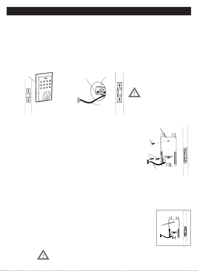
Figure 9a-f
Gasket
Control
Wire
Latch Hole
Figure 8a Figure 8c
C
3/4”(19mm) screw
(Optional Instalation)
Mounting Plate
Control Wire
B
9. SECURING THE EXTERIOR ASSEMBLY TO THE DOOR
door”, route the Control Wire through the
rectangular slot in the Mounting Plate
(Figure 9a).
b. Place Mounting Plate against door with tailpiece passing
through the center hole in the three hole set (Figure 9b).
c. Secure the Mounting Plate to the Exterior Assembly using
(Figure 9c).
d. Hand tighten with a Phillips Screwdriver leaving loosely connected (Figure 9d).
f. Check vertical alignment of the lock (Figure 9f).
DO NOT OVER TIGHTEN
10. OPTIONAL INSTALLATION
a. Using a 1/16” (2mm) drill bit, drill a pilot hole in your door using the
b. Insert one 3/4” (19mm) screw and tighten.
8. INSTALLING THE EXTERIOR ASSEMBLY
Work with the Door Open for easy access.
a. Unpack the Exterior Assembly. Use care to not scratch the green circuit board during handling and installation.
c. Insert the Exterior Assembly onto the door with the tailpiece going through the Deadbolt Latch Set cross
shaped spindle connector in the VERTICAL POSITION
Deadbolt Latch Set (Figure 8c).
NOTE: Tailpiece must be
positioned vertically
NOTE: Lock and unlock using the key to see if
the Deadbolt Latch is opening and closing easily.
INSTALLING EXTERIOR ASSEMBLY
Loading ...
Loading ...
Loading ...