Loading ...
Loading ...
Loading ...
electrical connection
D
A
NG
E
R
2
2
0
-2
40
v
o
lts
A
C
Dis
c
onn
e
ct
fr
o
m
s
u
pp
ly
be
fo
re
re
m
o
v
ing
p
anel
W
A
R
N
I
N
G
Do
n
ot
co
n
nect
b
att
e
r
y
ign
itio
n
m
o
de
ls
to
m
a
ins
s
u
p
p
ly
knob ignition switches
220-240V
ignition
box
1.50V
ignition
box
to burner spark plugs
to burner spark plugs
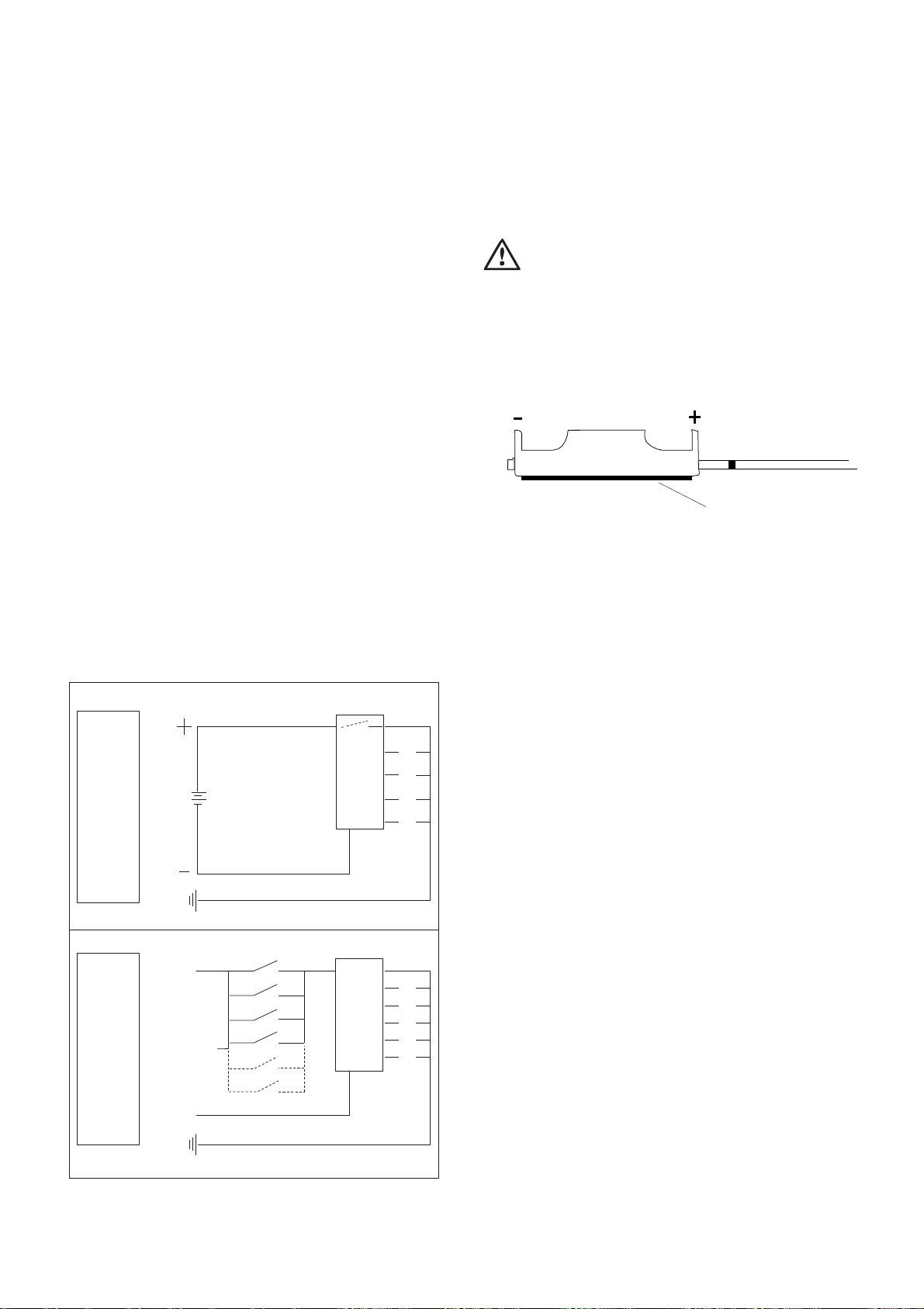
Battery connection
The battery used is a 1.5 Volt ‘AA’ Battery. This supplies the
power for the ignition system of the cooktop. To install, follow
the safety instructions as shown on Figure 8 below.
NOTE: Pay special attention to the orientation of the battery
when installing.
The battery supplied is a perishable item and not covered by
the warranty.
Electrical connection (220-240 Volts)
Where applicable, the appliance is supplied with a standard
7.5 Amp service cord terminated by a 3-pin plug for
connection to a standard household socket. The electrical
supply is required to power the electronic ignition system.
NOTE: It will be necessary for servicing purposes to
disconnect the electrical power supply. The power point
should therefore be accessible after the appliance is installed,
as specified in the local wiring regulations.
Diagram 1 is a schematic of the wiring in the appliance.
The weight of the unit is printed on the appliance packaging
label.
Diagram 1
Battery holder installation instructions
1.
Locate a convenient position to mount battery holder,
keeping it away from hot surfaces.
warning
DO NOT attach it to the base of the cooktop.
2.
Ensure mounting surface is clean.
3.
Remove protective tape from rear of holder and stick
in place.
Figure 8
double-sided tape
Use of hose assembles
Ensure that the hose assembly is restrained from accidental
contact with the flue outlet of an underbench oven or any
other hot surface of an adjacent appliance.
1.5V battery models
button
switch
1.5V
DC
E
220-240V models
A
220-240V
N
E
Gas Cooktops ELECTRICAL CONNECTION 15
Loading ...
Loading ...
Loading ...