Loading ...
Loading ...
Loading ...
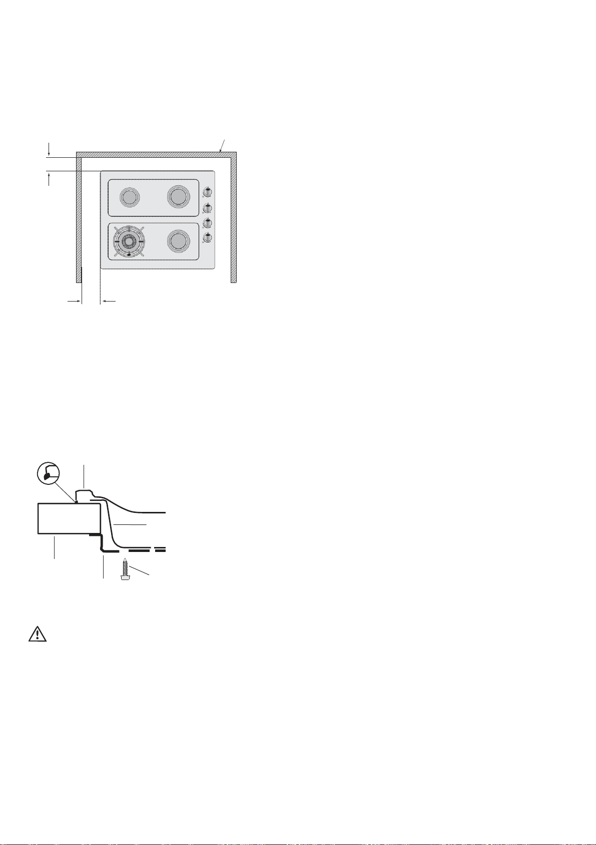
installation
Figure 5
110mm
115mm
wall
Operation on NG/SNG
Regulator
An appliance regulator is provided. The regulator must be
positioned so that the pressure test nipple is accessible when
the appliance is installed. Connect the gas supply to the ½ ”
B.S.P. internal thread inlet of the regulator. Refer to ‘bench
cutout’ (Figure 4) for connection point position.
Regulators are supplied pre-adjusted and configured by the
component maker for use with Natural Gas. The appliance
installer is not required to make an adjustment to obtain the
correct outlet pressure setting.
An arrow on the base of the regulator indicates the direction
of gas flow when the inlet and outlet of the regulator is
oriented correctly. When the regulator has been fitted check
for leaks from the connections with soapy water.
4.
Fitting the cooktop into the bench.
Carry out as
follows.
•
Place the rubber seal provided around the edge of the hob.
NOTE: The rubber seal has talc powder applied to it’s
surface which should be wiped off with a damp cloth
after the unit has been installed.
Figure 6
Gas connection
This appliance is supplied for use with Natural Gas.
However, it can be converted for use with LPG. Refer to LP
conversion on pages 13-15.
Supply pipe sizing
The total hourly gas consumption for the appliance is shown
on the data label. The required supply pressure (i.e. at inlet
to appliance regulator) for each gas type is shown on the
data label, and given in Table 3. Use this information in
rubber seal
benchtop
hob
clamp
burner box
screw
conjunction with the length of run, number of elbows, tees
and bends, the available service pressure and the supply
requirements of other installed appliances to determine
a suitable pipe size. For assistance in this matter refer to
the appropriate section of AS/NZS 5601.1 or
AS/NZS 5601.2.
An AGA certified class B or D flexible connection may be
used to connect the cooktop in accordance with AS/NZS
5601.1, in particular section 5.9 and clause 6.10.1.8, or
AS/NZS 5601.2, in particular section 2.11. Where a hose
assembly is used and the cooktop is in the installed position,
the hose assembly shall be suitable for connection to a fixed
•
Fit the pull-down clamps supplied to ensure that the
cooktop cannot move after installation.
warning
Failure to fix the cooktop to the bench could result in loosening of
the gas connection through movement of the cooktop and a gas
leak may result.
•
Use the 4 clamps and 4 screws supplied in the parts bag.
•
To assemble, attach the 4 clamps to each corner of the
burner box via the screw provided.
•
When placing the cooktop in the cut-out, swing the
clamps parallel with the box to avoid interference with the
cut-out.
•
Position the cooktop so it is centred, then swing the
clamps under the benchtop and tighten.
12 USING YOUR COOKTOP Gas Cooktops
consumer piping outlet located at a point 800 – 850mm
above the floor and in the region outside the width of the
appliance to a distance of 250mm. The point of connection
to consumer piping must be accessible with appliance
installed.
Elbow positioning
It is possible to reposition the elbow if required by loosening
the locking nut and elbow by using two spanners. Re-tighten
the entire assembly after the elbow has been repositioned.
When fitting elbow to appliance, ensure that the sealing
washer is fitted.
Loading ...
Loading ...
Loading ...