Installation Instructions and Use & Care Guide Residential Gas Water Heater
GETTING STARTED
1 Review all of the instructions before you begin work. If you aren’t sure that you can safely and properly do this work yourself, call your Lowe’s® store to arrange for Professional Installation (you may also call a qualified person of your choice, such as a licensed plumber, to have the work done). Improper installation can damage the water heater, your home, and other property, and can present risks of serious injury or death.
2 This water heater is design-certified by CSA International as a Category I, non-direct vented water heater which takes its combustion air either from the installation area or from air ducted to the unit from the outside. This water heater must be installed according to all local and state codes or, in the absence of local and state codes, the “National Fuel Gas Code”, ANSI Z223.1(NFPA 54)-current edition. This is available from the following:
CSA America, Inc. 8501 East Pleasant Valley Road Cleveland, OH 44131
National Fire Protection Association 1 Batterymarch Park Quincy, MA 02269
Check with local code officials about codes governing this installation. Have your installation inspected by a code official to ensure the installation meets all local codes
NOTICE: If you lack the necessary skills required to properly install this water heater, or you have difficulty following the instructions, you should not proceed but have a qualified person perform the on of this water heater.
Massachusetts code requires this water heater to be installed in accordance with Massachusetts 248-CMR 2.00 and 248-CMR 5.00: State Plumbing Code. Other local and state authorities may have similar requirements or other codes applicable to the installation of this water heater.
3 Before you start, be sure you have the following tools and supplies:
- Common plumbing tools (depending on what type of water pipes you have).
- Tefl on® tape or pipe joint compound approved for potable water.
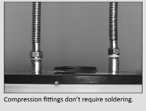
- For homes with copper pipes, you may purchase a Gas Water Heater Hook-Up Kit ( available from Lowes®) with compression fittings that don’t require soldering. This kit includes two 12” flex water lines, two compressions fittings, an 18” flexible gas line, two nipples, and Tefl on® tape.
- For homes with plastic pipe, use threaded connectors suitable for the specific type of plastic pipe used: CPVC or PEX (cross-linked polyethylene). Do not use PVC pipe.
- Non-corrosive gas leak detection solution made from hand dishwashing soap mixed with water (1 part soap to 15 parts water) or children’s soap bubbles and a small, soft -bristled brush.
- An appliance dolly or hand truck to move the water heater.
Recommended Accessories:
- A metal drain pan.
- Automatic water leak detection and shut-off device.
- Pressure Reducing Valve.
- Thermal Expansion Tank.
- Thermostatic Mixing Valves at each point-of-use.
- Fuel gas and carbon monoxide detector.
Combustion and Ventilation Air Supply
Before installing the water heater, you must determine the amount of air needed to supply this water heater and any other gas appliances in the same area and provide adequate air for combustion and ventilation. Consult a qualified person if you’re unsure of the proper way to supply air to your water heater.
WARNING! This gas water heater requires an adequate source of clean air for combustion and ventilation. Without sufficient air, your water heater will have frequent pilot outages and may emit excessive and abnormal amounts of carbon monoxide.
Before beginning:
Calculate total BTU/HR rating of all appliances.
To calculate the combusƟ on air and ventilation required, add up the total BTU/HR ratings of all gas burning appliances (e.g., water heaters, furnaces, clothes dryers) in the same area. Your water heater’s BTU/HR rating is on the data plate, located next to the gas control valve/thermostat. The BTU/HR ratings should be on the other appliances’ data plates. If you have trouble determining the BTU/HR ratings, contact the manufacturer or have a qualified person determine the ventilation requirements. NOTICE: If you are replacing your old water heater with one that has a higher BTU/HR rating, the amount of ventilation required may be greater.
Example:
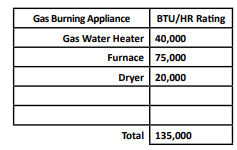
Your Appliances:
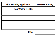
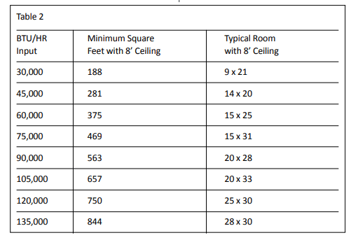
Table 2 provides examples of minimum square footage (area) required for various BTU/HR totals. Areas used for storage or which contain large objects containing less air than is assumed for the room sizes in Table 2 – see Option A for more specific calculations.
Option A: Installation without outside ventilation (not recommended)
Ventilation with outside air is recommended for all installations. Even if the water heater is installed in a large. open room inside the house. outdoor air is usually needed because modern homes are very tightly sealed and often do not supply enough air to the water heater. However. when installed in a large indoor space. it may be possible to provide enough air without outside ventilation. if you are unsure if your installation location has enough ventilation. contact your local gas utility company or code officials for a safety inspection.
The following instructions will help determine if it may be possible to install. without outside ventilation. Even if this may be possible. you will need to conduct the vent draft test on pages 23-24 when installation is finished. if there is not enough ventilation. you will need to ventilate with outside air.
Check for Chemicals:
Installations where corrosive chemicals may be present require outside ait. Air for combustion and ventilation must be clean and free of corrosive or acid-forming chemicals such as sulfur. fluorine. and chlorine. Ventilation with outside air will reduce these chemicals. but it may not completely eliminate them. Failure due to corrosive chemical als is not covered by the warranty.
Examples of locations that require outside air due to chemicals include:
- Beauty salons
- Photo processing labs
- Indoor pools
- Laundry, hobby,or craft rooms
- Chemical storage areas
Products such as aerosol sprays. de tergents. bleaches. cleaning solvents. gasoline. air fresheners. paint and varnish removers. and refrigerants should not be stored or used near the water heater.
A1: Calculate the air volume of the room
Air requirements depend on the size of the room.
Floor Area (Square feet) X CeilingnHeight (feet) = Room Volume (cubic feet)
If there are large objects in the room (eg. refrigerator, furnace, car). subtract their volume from the volume of the room to get a better estimate of the air available.
Room Volume - Object Volume = Air Volume
A2: Calculate required air volume
A water heater installed in an unconfined attic or garage requires that the space be at least 50 cubic feet per 1. 00 BTU/HR of the total input for all gas burning appliances in the same area. [Total BTU/HR/1000] x 50 = Cubic feet of air required.
Example: (135. 00 / 1000) x 50= 6. 50
If the air volume of the room is less than the required air volume. you must provide two permanent outside air openings that draw in sufficient air. Use Option 8.
If the air volume of the room is greater than the required air volume, it may be possible to install the water heater without outside ventilation.
A3: Check that combustion ventilation is adequate
Because modern homes are often well-sealed to prevent drafts. even a large room may not provide enough combustion air without ventilation. To confirm that your installation has enough combustion air, conduct the vent draft test on pages 23-24 when installation is finished.
Option B: Install with outside ventilation.
Ventilation with outside air is recommended. and. for most installations. is needed. There may be existing ventilation that is adequate, or you may need to add more ventilation.
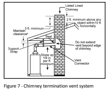
Supplying outside air to typically requires two openings. One opening must be within 12 inches from the floor and the second opening must be within 12 inches from the ceiling. Although a single opening is not preferred. you may use a single opening to outside air if the minimum free area is sized according to Table 3. Two openings must be used when ventilating with air from another room.
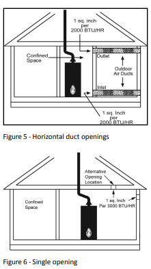
The outside air can be taken from a crawl space or attic open to the outdoors and adequately ventilated. You may use vertical or horizontal ducts.
B2: Determine type of ventilation
There are several types of ventilation that can be used :
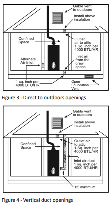
1. Direct to outdoors
2. Vertical ducts
3. Horizontal ducts
4. Single opening (not recommended, must be at least 100 square inches. Not appropriate for confined spaces smaller than 50 cubic feet per 1. 00 BTU/HR as calculated in section A or when getting air from another room.)
5. From a larger room inside the house (not recommended ~ refer to section A above to determine if the combined volume of the rooms may be adequate).
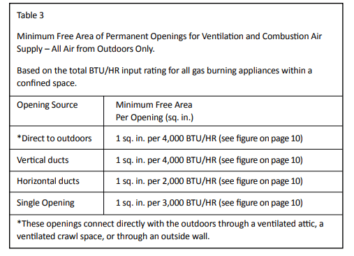
B3: Determine 1m free area required for each vent opening
The size of the vent openings depends on the total BTU/HR rating of all appliances in the space (use your calculation from “Before beginning”) and the type of vent used. Table 3 provides the mint mum free area for each vent opening depending on the type of ventilation.
B4: Calculate minimum size of vent openings and ducts
The vent cross-sectional area needed to provide the free area depends on the covering on the vent openings. Typical vents use louvers or grilles to protect the opening. The louver or grill itself blocks some of the free areas. so the opening may need to be larger to meet the minimum free area requirements.
Use the following formula to calculate the required cross-sectional area:
Cross-sectional area = minimum free area required + percent free area of
covering (in decimals — e.g. 60% = .6)
For example, an installation area that requires openings with 100 square inches of free area would need 134 square inch openings if using metal louvers rated at 75% free area (100 sq. in. + 75 = 134 sq.in.).
If you do not know the % free area for your louver or grill, use the following values:
- For wood louvers or grilles: 20%
- For metal louvers or grilles: 60%
Follow these rules to ensure that vents and ducts provide adequate air flow:
- Each vent opening must be no smaller than 100 square inches.
- Ducts must have the same cross-sectional area as free area of the opening.
- Rectangular ducts must have a minimum dimension of no less than three inches.
- All screens must have mesh ” or larger.
- Moveable louvers must be locked open or interconnected with the equipment so that they open automatically during operation.
- Keep louvers and grills clean and free of debris or other obstructions.
B5: Check that air source is clean and free of chemicals
Air for combustion and ventilation must be clean and free of corrosive or flammable chemicals. failure due to corrosive chemicals in the air is not covered by the warranty. Combustion air must be free of acid-forming chemicals such as sulfur, fluorine, and chlorine. Be sure that air at the vent inlets is free of such chemicals.
B6: Check that combustion ventilation is adequate
To confirm that your installation has enough combustion air, conduct the vent draft test on pages 23-24 when installation is finished.
Combustion Air Supply Options
Venting
WARNING! Carbon Monoxide Hazard. This water heater must be supplied with adequate air and vented to outdoors. The vent system must be installed by a qualified person. Examples of a qualified person include gas technicians, authorized gas company personnel, and authorized service technicians. Failure to properly vent the water heater can result in severe injury or death from carbon monoxide poisoning.
The vent system must be installed according to local and state codes. or in the absence of local or state codes. the current edition of the National Fuel Gas Code. ANSI 2223.1 (NFPA 54). Do not common vent this water heater with any power-vented appliance. Do not use a vent damper anywhere in the vent system of this water heater.
To reduce the risk of carbon monoxide poisoning, install a fuel gas and carbon monoxide detector. Install and maintain the detector in accordance with the manufacturer's instructions and local codes.
Replacing a Water Heater Using the Existing Vent System
Read the “Installing a New Vent System’' section of this manual and make sure your vent system is properly installed. Inspect the existing vent system for obstructions. corrosion. and proper installation. Repair or replace if necessary. The existing vent system must be UL listed Type B double wall or single wall metal vent pipe of either 3 inch or 4 inch diameter and installed according to the vent manufacturer's instructions and the terms of its listing. Do not use other materials such as dryer vent hose.
Installing a New Vent System
The vent pipe must meet the following specifications:
Type of Material
UL listed Type 8 double wall or single wall metal vent pipe must be used. Local codes may be more restrictive and may not allow single wall vent pipe. Single-wall vent pipe cannot be used for water heaters located in attics and may not pass through attic spaces, crawl spaces, or any confined or inaccessible location. Single-wall vent pipe cannot pass through any interior wall.
Clearance to Combustible Materials
The vent pipe cannot pass through any ceiling. floor. firewall. or fire partition. Any part of the vent system must maintain the following clearances from any combustible materials:
- Single-wall vent pipe must maintain a six-inch clearance from combustible materials.
- The clearance from combustible materials of UL listed Type B double-wall vent pipe is specified by the manufacturer of the vent pipe. UL listed Type 8 double-wall vent pipe may pass through walls or partitions constructed of combustible material if the minimum clearance specified by the manufacturer of the vent pipe is maintained.
Vent installation
To improve the flow of exhaust gases. we recommend that a minimum of 12 inches of vertical vent pipe be installed on the draft hood prior to any elbow. A portion of the vent pipe (up to 75% of the total vertical height) can be horizontal. but the termination must. be vertical. For the horizontal section. install without dips or sags with an upward slope of at least % inch per foot. install pipe avoiding unnecessary bends. Pipe joints must be fastened by sheet metal screws or other approved means. Support the pipe to maintain clearances and to avoid separation of joints or other damage. Vent pipe must be accessible for cleaning. inspection. and replacement.
Terminations
If local codes allow. this water heater may be terminated into an existing chimney using the instructions below.
Otherwise. this water heater’s vent must terminate vertically (sidewall or other horizontal terminations are not allowed).
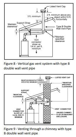
Chimney Termination
NOTICE: Before connecting a vent to a chimney. make sure the chimney passageway is clear and free of obstructions. The chimney must be cleaned if previously used for venting solid fuel appliances or fireplaces. Also, consult local and state codes for proper chimney sizing and application or. in the absence of local and state codes. the “National Fuel Gas Code”. ANSI 2223.1(NFPA 54)-current edition.
- The vent pipe must be installed above the extreme bottom of the chimney to prevent potentially blocking the flue gases.
- The vent pipe must be firmly attached and sealed to prevent it from falling out.
- To aid in removing the vent pipe. a thimble or slip joint may be used.
- The vent pipe must not extend beyond the inner edge of the chimney as it may restrict the space between it and the opposite wall of the chimney.
Do not terminate the vent pipe in a chimney that has not been certified for this purpose. Some local codes may prohibit the termination of vent connectors in a masonry chimney.
Common (combined) venting is allowable with vertical Type B vent systems and lined masonry chimneys as long as proper draft for the water heater is established under all conditions of operation. Do not common vent this water heater with any power vented appliance.
Vertical Termination
NOTICE: The gas vent must be terminated in a vertical position to facilitate the removal of exhaust gases.
Vertical exhaust vents must terminate with a listed cap or other roof assembly and be installed according to the manufacturer's instructions. An unused chimney flue or masonry enclosure may be used as a passageway for the installation of vent pipe. Do not commonly vent this water heater with any power vented appliance. The following figures are examples of vent pipe system installations and may or may not be suitable for your specific application. Consult the “National Fuel Gas Code”. NFPA 54. ANS! 2223.1-current. edition and local codes.
Gas Piping
Gas piping must be installed according to local and state codes or. in the absence of local and state codes. the “National Fuel Gas Code”. ANSI 2223.1 (NFPA 54)-current edition.
NOTICE: When installing gas piping. apply pipe joint compound or Teflon® tape approved for fuel gases.
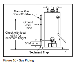
- Install a readily accessible manual shut-off valve in the gas supply as recommended by the local utility. Know the location of this valve and how to turn off the gas to this unit.
- Install a Sediment Trap as shown in the Gas Piping figure below. The Sediment Trap must be no less than three inches long for the accumulation of dirt. foreign material. and water droplets.
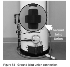
- Install a ground joint union between the gas control valve and the manual gas shut-off valve. This is to allow easy removal of the gas control valve.
- Turn the gas supply on and check for leaks. Use a small. soft-bristled brush to apply a hand dishwashing soap and water mixture (1 part soap to 15 parts water) or children’s soap bubbles to all connection points of the gas piping. Saturate all the connections and check for gas leaks (which will appear as small bubbles). If any leaks are detected. tighten the appropriate connection(s) and re-check.
Gas Pressure
NOTICE: When testing gas pipes with a test pressure of more than % psi (3.5 kPa). disconnect the gas line at the manual shut-off valve and cap the gas line. Do not subject the water heater’s gas control valve or manual shut-off valve to more than % psi (3.5 kPa) pressure for any reason. If you are pressure testing the gas line with test pressure of % psi (3.5 kPa) or less. you may isolate the water heater from the gas line by closing the manual shut-off valve.
Space Heating
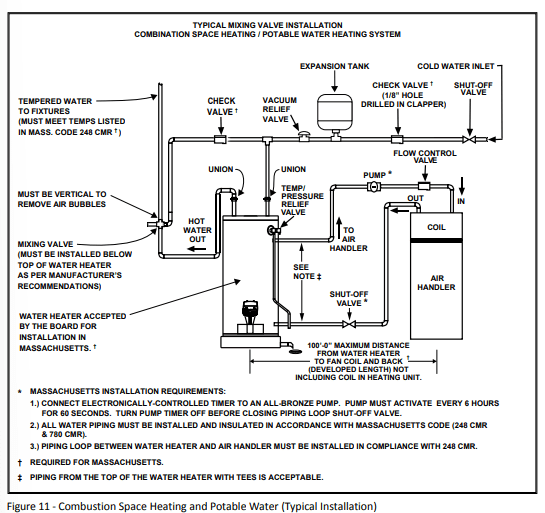
Some water heater models are equipped with inlet/outlet connections for use with space heating applications. if this water heater is to be used to supply both space heating and domestic potable (drinking) water, the instructions listed below must be followed.
- This water heater is suitable for combination water (potable) heating and space heating and not suitable for space heating applications only.
- Be sure to follow the manual(s) shipped with the air handler system.
- This water heater is not to be used as a replacement for an existing boiler installation.
- Do not use with piping that has been treated with chromates. boiler seal or other chemicals and do not add any chemicals to the water heater piping.
- If the space heating system requires water temperatures in excess of 120°F. install a Thermostatic Mixing Valve in the domestic (potable) hot water supply at each point-of-use to limit the risk of scald injury. Install the mixing valve per its manufacturer’s instructions.
-
Pumps. valves. piping. and fittings must be compatible with potable water.
-
A properly installed flow control valve is required to prevent thermosiphon ing. Thermosiphon is the result of a continuous flow of water through the air handler circuit during the off cycle.
-
The domestic hot water line from the water heater should be vertical past any mixing valve or supply line to the air handler to remove air bubbles from the system. Otherwise, these bubbles will be trapped in the air handler heat exchanger coil, reducing efficiency.
-
Do not connect the water heater to any system or components previously used with non-potable water heating appliances when used to supply potable water.
Solar Installation
If this water heater is used as a solar storage heater or as a backup for the solar system. the water supply temperatures to the water heater tank may be in excess of 120°F. A Thermostatic Mixing Valve or other temperature limiting valve must be installed in the water supply line to limit the supply temperature to 120°F. The unit must be set to Standard Mode (See Operating Modes in Operation section on page 24).
NOTICE: Solar water heating systems can often supply water with temperatures exceeding 180°F and may result in water heater malfunction.
INSTALLATION
Step 1:
Verify that your home is equipped and up-to-date for proper operation
Installing a new water heater is the perfect time to examine your home’s plumbing system and make sure the system is up to current code standards. There have likely been plumbing code changes since the old water heater was installed. We recommend installing the following accessories and any other needed changes to bring your home up to the latest code requirements. Updating your plumbing system can help extend the life of your water heater. avoid damage to your home and property. and reduce the risk of serious injuries or death. Inspect your home and install any devices you need to comply with current codes and assure that your new water heater performs at its best. Check with your local plumbing official for more information.
Water pressure
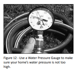
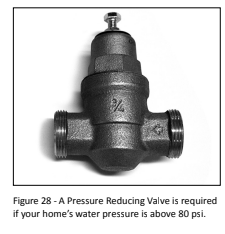
Most codes allow a maximum incoming water pressure of 80 psi (we recommend a working pressure no higher than 50-60 psi). Check your home’s water pressure with a pressure gauge and adjust if necessary. High water pressure can damage the water heater, piping, and other appliances.
HOW: Purchase an inexpensive water pressure gauge from Lowe’s®. Connect the water pressure gauge to an outside faucet and measure the maximum water pressure experienced throughout a 24-hour period (highest water pressures oŌ en occur at night).
To adjust your home’s water pressure: Locate your home’s Pressure Reducing Valve (PRV) on the main incoming (cold) water supply line and adjust the water pressure control to between 50 and 60 psi. If your home does not have a Pressure Reducing Valve, install a PRV on the home’s main water supply line and set it to between 50 and 60 psi. Pressure Reducing Valves are available at Lowe’s®.
BACKGROUND: Over the years, many utilities have increased water supply pressures so they can serve more homes. In some homes today, pressures can exceed 100 psi. High water pressures can damage water heaters, causing premature leaks. If you have replaced toilet valves, had a water heater leak, or had to repair appliances connected to the plumbing system, pay particular attention to your home’s water pressure. When purchasing a PRV, make sure the PRV has a built-in bypass.
Water pressure increase caused by thermal expansion
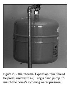
Verify that you have a properly sized Thermal Expansion Tank. We recommend installing an expansion tank if your home does not have one. Plumbing codes require a properly pressurized, properly sized Thermal Expansion Tank in almost all homes.
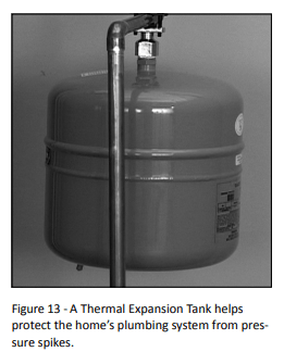
HOW: Connect the Thermal Expansion Tank (available from Lowe's®) to the cold water supply line near the water heater. The expansion tank contains a bladder and an air charge. To work properly, the Thermal Expansion Tank must be sized according to the water heater’s tank capacity and pressurized to match the home’s incoming water pressure. Refer to the instructions provided with the Thermal Expansion Tank for installation details.
BACKGROUND: Water expands when heated. and the increased volume of water must have a place to go. or thermal expansion will cause large water pressure (despite the use of a Pressure Reducing Valve in the home’s main water supply line). The Safe Drinking Water Act of 1974 requires the use of backflow preventers and check valves to restrict water from your home reentering the public water system. Backflow preventers are often installed in water meters and may not be readily visible. As a result, most all plumbing systems today are now “closed,” and almost all homes now need a Thermal Expansion Tank
A Thermal Expansion Tank is a practical and inexpensive way to help avoid damage to the water heater, washing machine, dishwasher, ice maker. and even toilet valves. If your toilet occasionally runs for no apparent reason (usually briefly at night). that may be due to thermal expansion increasing the water pressure temporarily.
Water Pipe and Tank Leaks
Leaks from plumbing pipes or from the water heater itself can damage property and could cause a fire risk.
Install an automatic leak detection and shutoff device (available from Lowe's). These devices can detect water leaks and can shut off the water heater’s water supply if a leak occurs.
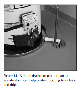
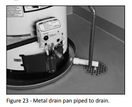
Install a metal drain pan (available from Lowe's® ) under the water heater to catch condensation or leaks from the piping connections or tank. Most codes require. and we recommend, installing the water heater in pan that is piped to an |The drain pan must be at least two inches wider than the diameter of the water heater. Install the drain pan so the water level would be limited to a maximum. depth of 1-3/4”. The pan must not restrict airflow to the burner.
Water Temperature Regulation
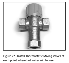
Install Thermostatic Mixing Valves to regulate the temperature of the water supplied to each point-of-use (for example. kitchen sink. bathroom sink. bath. shower). Install and adjust the mixing valve according to its manufacturer’s instructions.
A WARNING! Even if the water heater’s thermostat is set to a relatively low temperature. hot water can scald. Install Thermostatic Mixing Valves at each point-of-use to reduce the risk of scalding.
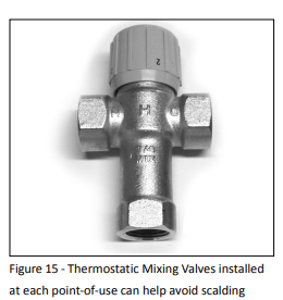
BACKGROUND: A Thermostatic Mixing Valve, installed at each point-of-use, mixes hot water from the water heater with cold water to more precisely regulate the temperature of hot water supplied to fixtures. If you aren’t sure if your plumbing system is equipped with properly installed and adjusted Thermostatic Mixing Valves at each point where hot water is used, contact a qualified person.
Step 2:
Verify that the location is appropriate
WARNING! Do not store or use flammable materials, vapors, or liquids in the same location where this water heater is installed.
- Before installing your water heater. ensure that it will be located:
- Indoors in an area with adequate air supply.
- In an area that will not freeze.
- As close as possible to a chimney or vent.
- In a metal drain pan piped to an adequate drain
- In an area suitable for vertical installation.
- In an area with adequate space (clearances) for periodic servicing (there must be a minimum of 24 inches of front clearance).
- In an area that allows a mi clearance from combustible surfaces as stated on the data plate.
- On a floor that can support the weight of a water heater full of water.
You will also want to follow these guidelines while considering an appropriate location:
- Do not install near air-moving devices such as exhaust fans. ventilation systems. or clothes dryers.
- Do not obtain ventilating air for the furnace/air handler from the same space as the water heater. Ensure that any return air ducts near the water heater are sealed.
- If the water heater is located in an area subject to lint, dust, or oily vapors. at least annually check and clean the air filter. See Maintenance section for steps on cleaning the air filter.
- Do not install in a bathroom. bedroom. or any occupied room normally kept closed.
- If the water heater is installed directly on carpeting. it shall be installed on a metal or wood panel extending beyond the full width and depth of the water heater by at least 3 in (76.2mm) in any direction. if the water heater is installed in an alcove or closet. the entire floor shall be covered by the aforestated panel.
- If your area is prone to earthquakes. use special straps as required by local building codes.
NOTICE: The state of California requires bracing. anchoring. or strap ping the water heater to avoid its moving during an earthquake. Contact local utilities for code requirements in your area, visit http://www.dsa.dgs. ca.gov. or call 1-916-445-8100 and request instructions. Other locations may have similar requirements. Check with your local and state authorities.
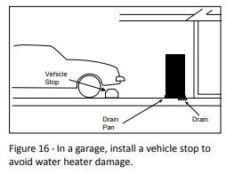
- Do not install in a location prone to physical damage by vehicles. flooding. or other risks.
- Avoid locations such as attics. upper floors. or where a leak might damage the structure or fur ings. Due to the normal corrosive action of water. the tank will eventually leak. To my property damage from leaks. inspect and maintain your water heater in accordance with this manual’s instructions. Install a metal drain pan under the water heater piped to an adequate drain. Inspect the drain pan, pipes, and surrounding area regularly and fix any leaks found.
Step 3:
Removing the old water heater
1. Read each installation step and decide if you have the necessary skills to install the water heater. Only proceed if you are comfortable you can safely perform the work. If you are not sure, have a qualified person perform the installation.
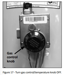
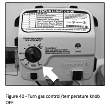
2. On the old water heater, turn the control knob on the gas control valve to the OFF position
3 Turn the manual gas valve for the water heater’s supply line OFF.
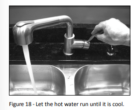
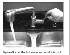
4 Open a hot water faucet and let the hot water run until it is cool (This may take 10 minutes or longer).
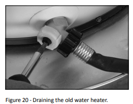
5. Connect a garden hose to the drain valve and place the other end of the hose in a drain, outside, or in buckets. (Sediment in the bottom of the tank may clog the valve and prevent it from draining. If you can’t get the tank to drain, contact a qualified person.)
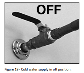
6 Turn the cold water supply valve OFF.
7. Using a standard fl at-blade screwdriver, open the drain valve. Sediment build-up in the bottom of the water heater may hinder or prevent draining.
8 Also open a hot water faucet to help the water in the tank drain faster.
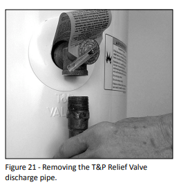
9 When the tank is empty, disconnect the Temperature & Pressure (T&P) Relief Valve discharge pipe. You may be able to reuse the discharge pipe, but do not reuse the old T&P Relief Valve. A new T&P Relief Valve comes with your new water heater.
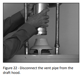
10 Allow the vent pipe and draft hood to cool. Once cooled, disconnect the vent pipe from the draft hood. You may need to support the vent pipe until the new water heater is in place.
11. Disconnect the water pipes. Many water pipes are connected by a threaded union which can be disconnected with wrenches. If you must cut the water pipes, cut the pipes close to the water heater’s inlet and outlet connections, leaving the water pipes as long as possible. If necessary, you can make them shorter later when you install the new water heater.
12 Confirm the manual gas valve for the water heater’s supply line is turned off. Disconnect the gas line from the water heater’s gas control valve and cap it.
13 Remove the old water heater. Use an appliance dolly or hand truck to move the water heater
WARNING! Use two or more people to remove or install a water heater. Failure to do so can result in back or other injuries
Step 4:
Installing the New Water Heater
1. Completely read all instructions before beginning. If you are not sure you can safely complete the installation. seek assistance from any of the following sources:
- Lowe's® Professional Installation is available for this product and the work is guaranteed. Call your Lowe's® store to have this water heater installed.
- Schedule an appointment with a qualified person to install your water heater.
- Call our Technical Assistance Hotline at.
2. Install a metal drain pan that is piped to an adequate drain.
3. Set the water heater in place taking care not to damage the drain pan. When installing directly on carpet. the water heater must be installed on a wood or metal base that extends beyond the dimensions of the water heater (width and depth) by at least 3 inches (76.2 mm) in any direction. If the water heater is installed on carpet in an alcove or closet. the entire floor must be covered by a wood or metal panel.
NOTICE: Most codes require setting the water heater in a metal drain pan piped to an adequate drain. The drain pan helps avoid property damage which may occur from condensation or leaks in the piping connections or tank. The drain pan must be at least two inches wider than the diameter of the water heater. Install the drain pan so the water level is limited to a maximum depth of 1-3/4”.
4. Verify that the water heater is set in place properly. Check that:
- There is adequate space to install the T&P Relief Valve discharge pipe and that it can be piped to a separate drain (and not into the drain pan).
- There is adequate access and space around the water heater for future maintenance.
The water heater is installed vertically.
Step 5:
Air Filter Installation
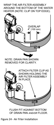
Once you've positioned the water heater in the installation area. install the wrap-around air filter (supplied with the water heater). The wrap-around air filter fits around the base of the unit. Do not operate the water heater without a clean air filter in place.
1. Before installing the Air Filter Assembly. remove any dust. lint or debris (including any packaging materials or tape) from under the water heater.
2. Installation: Wrap the filter around the base of the water heater. Cut to fit around a sensor if present. Trim excess filter material with scissors but allow filter material to overlap a few inches (see Figure 2).
3. The filter should fit snugly against base of the water heater with no gaps. The filter must fit flush against the bottom of the drain pan and/or floor. Hold the filter in place. then stretch the filter clip over the overlapped joint and hook in place (see Figure 24).
4 Check the filter at least every three months and clean as necessary. After installation, the filter may be cleaned by using a vacuum cleaner with a brush attachment to remove lint and dust.
NOTE: because the amount of dust and lint in the air can vary, your filter may need to be inspected/ cleaned more often. In some instances, the filter may need to be removed and washed using mild hand soap and water to remove any oily residue. After washing, allow to dry and properly reinstall.
Step 6:
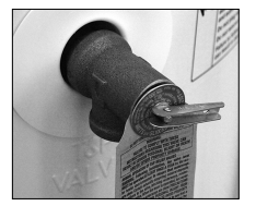
Connect the Temperature and Pressure (T&P) Relief Valve/Pipe
Most T&P Relief Valves are pre-installed at the factory. In some cases, they are shipped in the carton and must be installed in the opening marked “T&P Relief Valve” and according to local codes.
WARNING! To avoid serious injury or death from explosion, install a T&P Relief Valve according to the following instructions:
1 If the T&P Relief Valve was not factory installed, install the new T&P Relief Valve that came with your water heater. Do not reuse an old T&P Relief Valve.
- The discharge pipe should be at least 3/4” inside diameter and sloped for proper drainage. Install it to allow complete drainage of both the T&P Relief Valve and the discharge pipe.
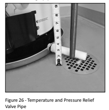
- The discharge pipe must not be smaller than the pipe size of the T&P Relief Valve. The pipe must also be able to withstand 250°F (121°C) without distortion. Use only copper or CPVC pipe. Do not use any other type of pipe. such as PVC. iron. flexible plastic pipe. or any type of hose.
- Terminate the discharge pipe a maximum of six inches above a floor drain or outside the building. Do not drain the discharge pipe into the drain pan; instead, pipe it separately to an adequate drain. In cold climates, terminate the discharge pipe inside the building to an adequate drain. Outside drains could freeze and obstruct the drain line—protect the discharge pipe from freezing.
- Do not place any valve or other restriction between the tank and T&P Relief Valve. Do not cap. block. plug. or insert any valve between the T&P Relief Valve and the end of the discharge pipe. Do not insert or install any reducer in the discharge pipe.
Step 7:
Install Shutoff and Thermostatic Mixing Valves
1. If one is not already installed, install a manual shutoff valve in the cold waterline that supplies the water heater. Install the shutoff valve near the water heater so that it is readily accessible. Only use a full low ball or gate valve compatible with potable water.
2. Install a Thermostatic Mixing Vale at each point-of-use (for example, kitchen sink, bathroom sink, bath, shower) per the valve manufacturer's instructions
WARNING! Even if the water heater’s thermostat is set to a rela tively low temperature. hot water can scald. Install Thermostatic Mixing Valves at each point-of-use to reduce the risk of scalding.
3. For water heaters that are fed by a solar water heating system (or any other preheating system). always install Thermostatic Mixing Valve or other temperature-limiting devices in the inlet water supply line to limit water supply inlet temperature to 120°F. Solar water heating systems can supply water with temperatures exceeding 180°F and may result in water heater malfunction.
WARNING! Hot water provided by solar heating systems can cause severe burns instantly. resulting in severe injury or death.
IF YOU HAVE COPPER PIPES:
If your home has copper water pipes. you can solder the water pipe connections or use compression fittings which don't require soldering. Compression fittings are easier to install than soldering pipe. Check with local plumbing officials to determine what types of pipe materials are suitable for your location. Do not use lead-based solder.
NOTICE: Do not solder pipes while they are attached to the water heater. The water heater’s inlet and outlet
connections contain non-metallic parts which could be damaged. The proper way to connect the water heater to copper water pipes is as follows:
* Solder a short length of pipe (about 2 foot or so) to a threaded adapter. Using only 95/5 tin-antimony or equivalent solder. Attach the threaded adapters to the water heater’s connections (using Teflon tape or pipe joint compound). Connect the home's water pipes by soldering. keeping the connections at the water heater cool with wet rags.
Step 8:
Connect the Water Supply
Note that all piping and components connected to the water heater must be suitable for use with potable water.
1. Determine the type of water pipes in your home. Most homes use copper water pipes. but some use CPVC or cross-linked polyethylene (PEX). Use fittings appropriate for the type of pipe in your home. Do not use iron or PVC pipe.
2. Connect the cold water supply using 3/4 inch National Pipe Thread “NPT” to the fitting marked “C” (COLD).
For ease of removing the water heater for service or replacement. connect. the water pipes with a coupling called a union. We recommend using a dielectric-type union (available from Lowe's). Dielectric unions can help prevent corrosion caused by tiny electric currents common in copper water pipes and can help extend the life of the water heater.
NOTICE: Most water heater models contain energy-saving heat traps in the inlet and outlet connections. Do not remove the heat traps.
3 Connect the hot water supply using 3/4 inch NPT to the fittng marked “H” (HOT).
4. Install insulation (or heat tape) on the water pipes especially if the door installation area is subject to freezing temperatures. Insulating the hot water pipes can increase energy efficiency.
5. Adjust (or install) the home's Pressure Reducing Valve to 50-60 psi and install a Thermal Expansion Tank.
Step 9:
Verify Connections and Completely Fill Tank
To remove air from the tank and allow the tank to fill completely with water. follow these steps:
1. Remove the aerator at the nearest hot water faucet. This allows debris in plumbing system to be washed out of the pipes.
2 Turn the cold water supply back on and fill the tank.
3. Open a hot water faucet and allow the water to run until it flows with a full stream.
4. Let the water run full stream for three minutes.
5. Close the hot water faucet and replace the aerator.
6. Check inlet and outlet connections and water pipes for leaks. Dry pipes connection so that any drips or leaks will apparent. Repair any leaks. Almost all leaks occur at connection and are not a tank leak.
Step 10:
Install Draft Hood
1. Install the new draft hood by aligning the legs and inserting them into the slots provided on top of the water heater. Do not reuse the draft hood from the old water heater. but rather use the new one that came with your new water heater.
2. Secure the draft hood using the four screws provided. Attach the home's existing vent pipe to the draft hood outlet using an approved vent adapter (not supplied).
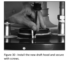
3 Secure the vent adapter to the draft hood with sheet metal screws. Read the Vent ng section on page 11. Make sure your home’s venƟ ng system complies with the instructions in this manual and is in good condition.
Step 11:
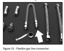
Make Gas Connections
The Gas Water Heater Hook-Up Kit (available at Lowe’s®) includes a flexible gas connector with compression fittings to connect the home’s gas line to the water heater’s gas control valve. Follow the kit’s installation instructions to attach the flexible gas connector.
Once you've made the gas connections. use a small. soft-bristled brush to apply a hand dishwashing soap and water mixture or children’s soap bubbles (1 part soap to 15 parts water) to all connection points of the gas line and flexible gas connector (if used). Make sure to generously coat all the connections and check for gas leaks (which will appear as small bubbles). If any leaks are detected. turn the gas supply off, tighten the leaking connection and re-check.
BEFORE LIGHTING THE WATER HEATER...
Make sure all checklist items have been completed.
- Water Heater Location
- Installation area free of corrosive or flammable materials. liquids or vapors
- Proper clearances from combustible surfaces maintained and sufficient room to service the water heater.
- Not installed directly on a carpeted floor.
- Metal drain pan installed and piped to an adequate drain
- Water heater is not located near an air-moving device (fan. clothes dryer)
- Not in a location with large amounts of lint. dust. etc. (If so, the air filter or flame arrestor located on the bottom of the water heater will need to be cleaned more often.)
Combustion Air Supply and Ventilation
- Adequate air supply for water heater and any other nearby gas appliances.
If the water heater is installed in a closet or other small, enclosed space or within the living space of the house, air supply openings needed.
- Are the openings of sufficient size?
- Ductwork is the same cross-sectional area as the openings?
- Outside air openings are preferred and may be required in tightly built homes
Vent Pipe System
- New draft hood. properly installed
- Vent pipe securely fastened to draft hood with screws and sup ported property
- Vent pipe made of approved material and either 2” or 3” in diameter.
- Vent system installed according to local and state codes or. in the absence of local and state codes. the "National Fuel Gas Code". ANSI 2223.1(NFPA 54)-current edition.
- Check existing vent system for rust. restrictions/obstructions.
Water System Piping
Temperature and pressure relief valve properly installed with a discharge line run to an adequate drain and protected from freezing.
- Water pipes free of leaks.
- Water heater completely filled with water.
- Thermal Expansion Tank installed
- Water Pressure Reducing Valve installed and adjusted to 50-60 ps.
- Thermostatic Mixing Valves installed at each point-of use.
Gas Supply and Piping
- Gas type is the same as that listed on the water heaters data plate
- Gas line equipped with shutoff valve
- Adequate gas pipe size and ap proven gas pipe material.
- All gas connections and fittings leak checked and any leaks corrected
OPERATION
Lighting Instructions
A WARNING! Explosion Hazard ~Replace viewport if glass is missing or damaged. Failure to do so can result in death. explosion or fire.
Read and understand these directions thoroughly before attempting to light or relight the pilot. Make sure the viewport is not missing or damaged. Make sure the tank is completely filled with water before lighting the plot. Check the data plate near the gas control valve to ensure the correct gas type. Do not use this water heater with any gas other than the one listed on the data plate. if you have any questions or doubts. consult your gas supplier or gas utility company.
NOTICE! A newly installed water heater will have air in the gas line. It may take several lighting attempts to clear all the air from the gas line and light the pilot.
Follow these steps to light the pilot:
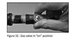
1. Make sure the manual gas valve for the water heater’s supply line is ON.
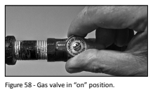
2 Turn the gas control knob to the PILOT on.
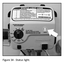
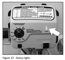
3. Press the gas control knob in fully and hold it in. While holding in the gas control knob. repeatedly click the igniter button (approximately once per second) for up to 90 seconds or until the Status Light starts to flash. You can tell the pilot is lit when the Status Light flashes once every three seconds.
4. Once the Status Light starts flashing. release the gas control knob. Adjust the gas control knob to the desired temperature setting.
5. If the Status Light doesn’t start flashing after 90 seconds. release the gas control! knob: and wait 10 minutes.
6. Repeat lighting steps 2 through 5 at least two additional times or until the Status Light starts flashing once every three seconds. Wait 10 minutes between lighting attempts.
7. A solid Status Light means the pilot was lit but is now off. Release the gas control knob and wait 10 minutes. Once the Status light goes out. repeat lighting steps 2 through 5.
8. If the Status Light doesn’t start flashing after three lighting attempts. turn the gas control knob to the OFF position and refer to the “Troubleshooting-No Hot Water” section (see page 25).
9. When a gas water heater is first lit and the tank is cold, condensation often forms inside the water heater. You may hear drips or a sizzling sound when the water heater is first lit or, you may see a small puddle on the floor. Condensation is not a leak and will go away once the tank reaches normal operating temperature.
10. The air filter at the bottom of the water heater must be cleaned from time to time. See the Maintenance section for steps on cleaning the air filter. If the air filter is not cleaned as needed. the water heater’ pilot may go out.
Shut down Instructions
Turn the gas control/temperature knob counterclockwise to the "OFF" setting. The status light will stop blinking and stay (on for a short time after the water heater is turned off.
Emergency Shut down
Should overheating occur or the gas supply fail to shut off. tur ofthe water heater’s manual gas control valve and call a qualified person.
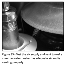
Checking the Vent System and Air Supply
Once the water heaters lit and the gas control knob is set to the desired temperature. the burner will light (if the tank is cold) Perform an air supply and vent test to make sure the unit is venting properly and the air supply is adequate:
1 The main burner must be on for this test. with a newly installed water heater full of cold water. turning the temperature control knob to HOT should cause the main burner to come on. You can view the burner through the sight glass at the base ofthe water heater.
2 Close all windows and doors and turn on all gas appliances and air-moving devices (range hoods. bathroom exhaust fans. ceiling fans. etc.) in your home. Also. close any fireplace dampers.
3 Allow the water heater’s main burner to operate for five minutes. Pass anew extin guished match approximately one inch from the draft hood's relief opening. Smoke from the match should be steadily drawn into the opening indicating the water heater is getting adequate air and the vent system is working.
4 If the main burner has been operating for five minutes but the match smoke drifts around or is blown away from the opening. turn the gas control knob OFF. Inspect the vent system and repair if necessary. In many cases, failure to pass the air supply and vent test indicate the water heater is not getting enough air or there is a problem with the vent system. It may be necessary to increase the air supply by getting air from outside (see page 7).
WARNING! Burn Hazard. Do not touch the vent. doing so can cause burns. If the draft hood does not draw in smoke from a match after five minutes of main burner operation. shut the gas supply off. and do not operate the water heater until the vent system and air supply have been checked by a qualified person and repaired if necessary. Continuing to operate the water heater it condition could lead to serious injury or death from carbon monoxide poisoning.
Temperature Control System
Adjusting the Temperature
With the installation steps completed. you may adjust the water heater’s temperature setting if desired
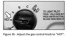
1 Set the gas valve to the desired temperature. the "HOT" setting sets the water temperature to approximately 120°F. reducing the risk of scald injury. You may wish to set a higher temperature to provide hot water for automatic dishwashers or laundry machines, to provide more hot water capacity, and to reduce bacterial growth. Higher tank temperatures (140° F) kill bacteria that cause a condition known as “smelly water” and can reduce the levels of bacteria that cause water-borne diseases.
Water usage patterns. as well as heat from sources such as solar collectors. ambient air. and the pilot light can result in temperatures higher than the thermostat set point.
WARNING! Higher temperatures increase the risk of scalding. but even at 1120°F. hot water can scald (see Table 1). Install Thermostatic Mixing Valve(s) at each point-of-use to reduce the risk of scalding.
2 To adjust the water heaters thermostat
- “A” 128°F
- “B” 138°F
- “C” 147°F
- “VERY HOT” 160°F
NOTICE: The temperatures above are approximate. The actual temperature of the heated water may vary.
3 Wait for the water to heat up. If you have no hot water after two hours. refer to the Troubleshooting Section (see page 25).
NOTICE: If the tank is full of cold water. condensation may form inside the water heater. This condensation may {drop on the burner causing a sizzling sound. In some cases. you may see a small puddle on the floor. Condensation is normal and should go away once the tank reaches its normal operating procedure.
WARNING! If you have increased the temperature setting and the Thermostatic Mixing Valves are not set properly (or not installed) you could scald yourself while checking the temperature.
4 Check water temperature at several points of use in your home (for example. bathtub faucet, shower, or lavatory sink) and adjust the Thermostatic Mixing Valves as needed. If you aren't sure how to adjust the Thermostatic Mixing Valve settings or aren't sure if you have Thermostatic Mixing Valves. contact a qualified person.
Operating Modes
The gas control valve has two differ cent operating modes: Standard and Vacation. The Standard mode allows you to adjust the water temperature to your desired setting. The Vacation (VAC) mode sets the thermostat at approximately 55°F and is recommended when not using hot water for an extended period of time. The VAC setting also reduces energy losses and keeps the tank from freezing during cold weather but can cause a Hydrogen gas build up. See caution on page 6.
TROUBLESHOOTING
No Hot Water
Use the following step-by-step plan as a guide to help determine why you have no hot water:
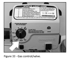
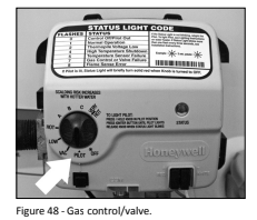
1 Check the Status Light
The Status Light on the gas control valve flashes once every three seconds if the pilot is lit and the gas control valve has not detected any problems.
If the Status Light is flashing once every three seconds and you have no hot water, make sure the gas control knob is set to HOT.
If the Status Light flashes more than once every three seconds, refer to the Status Light Code Troubleshooting Chart on page 27.
If the Status Light is not flashing, go to step 2.
2 Status Light is Not Flashing
If the Status Light isn’t flashing, try lighting the pilot using the ng instructions on page 23.
If you have tried lighting the pilot and the Status Light does not flash, go to step 3.
If the Status Light flashes, go to Step 1.
3 Checking the Pilot Light
Check the spark igniter. Dim the room lights and look through the viewport while clicking the igniter button.
If you don’t see a spark through the viewport, check to make sure the igniter wire is firmly inserted into the white connector.
If you see a spark, make sure the gas supply valve is turned on, and try lighting the pilot using the lighting instructions on page 23.
If the pilot still does not light, call a qualified person.
Insufficient Hot Water or Slow Hot Water Recovery
WARNING! Because of the increased risk from scalding, if you set the water heater’s gas control knob higher than 120°F, install Thermostatic Mixing Valves at each point-of-use. Due to the increased risk of scalding, do not set the temperature of the Thermostatic Mixing Valves above 120°F.
If the hot water is simply not warm enough, there are several possible causes:
- Faulty Thermostatic Mixing Valve in a faucet or shower control (check other faucets in the house for hot water)
- Water heater’s capacity is too small (or usage too high).
- Reversed plumbing connections cr melted dip tube (usually found soon after new installation).
- Plumbing leak.
- Sediment or lime build up in the bottom of the tank.
Thermostatic Mixing Valves. If the hot water is simply not warm enough, make sure the faucet you are checking doesn't have a defective Thermostatic Mixing Valve. Many shower controls now have built-in mixing valves. If these devices fail, they can reduce the amount of hot water the shower or faucet delivers even though there is plenty of hot water in the tank. Always check the water temperature at several faucets to make sure the problem is not in a faucet or shower control
Undersized Water Heater. If your water heater runs out of hot water quickly, it may be too small for your needs. If the water heater is old. consider replacing it with a larger model. If the water heater is in good condition, you may be able to meet your family’s hot water needs with the existing water heater by installing Thermostatic Mixing Valves at each point-of-use and then turning the gas control knob to a higher setting.
You can also reduce your home's hot water needs by washing clothes in cold water. installing flow restrictors on shower heads. repairing leaky faucets, and taking other conservation steps.
Reversed Connections or Melted Dip Tube. Check the hot and cold water connections and make sure your home's hot water pipe is connected to the hot water outlet on the water heater. Usually, reversed connections are found soon after the installation of a new unit. If copper pipes were soldered while they were attached to the water heater, the dip tube may have melted. The dip tube is a long, plastic tube inside the tank attached to the cold water inlet. If the dip tube has melted, it can be replaced by removing the cold water inlet connection, removing the old dip tube and installing
Plumbing Leak. Even a small leak in the hot water side of the home's plumbing system can make it appear that the water heater is producing little to no hot water. In this case. the burner will be on all or almost all the time. yet you will have very little hot water. Locate and repair the leak.
Sediment or Lime in Tank. With an existing water heater. if you have some hot water but not as much as you're used to. there may be a build up of sediment or ime on the bottom of the tank. Sediment or lime build up can reduce the efficiency of your water heater. Heavy deposits can damage the water heater. See the Maintenance section for steps on draining and flushing the water heater.
Temperature Too High
Adjust the thermostat on the water heater to a lower setting. Install or adjust Thermostatic Mixing Valves for each point-of-use (see the valve manufacturer's instructions).
Low Water Pressure
Check both the cold and hot water at a sink to determine if the lower pressure is only on the hot water side.
If both hot and cold faucets have low pressure. call your local water utility. If the low pressure is only on the hot water side. the primary causes are:
- Melted heat traps or dip tube. Soldering copper pipes while they are connected to the water heater can melt the heat traps inside the hot and cold water connections or the dip tube (cold waterside). Melted heat traps or a melted dip tube an restrict the flow of hot water. If that’s the case. replace the heat traps or dip tube.
- Partially closed supply valve. Open the water heater's supply valve fully.
Drips from T&P Relief Valve Discharge Pipe
A small amount of water dripping from the Temperature and Pressure (TP) Relief Valve usually means the home's water pressure is too high and/or you need a Thermal Expansion Tank. See Step 1 in the Installation section of this manual for more information
A large amount of hot water coming from the T&P discharge pipe may be due to the tank overheating. If the
T&P relief valve is discharging large amounts of very hot water. turn the gas supply valve off and call a qualified person.
WARNING! DO NOK Cap or plug the T&P Relief Valve or discharge pipe. and do not operate the water heater without a functioning T&P Relief Valve—this could cause an explosion.
Water Pressure too High. High water pressure can cause the T&P Relief Valve to drip. Install a Pressure Reducing Valve (PRV) on the main cold water supply line. Adjust the PRV to between 50 and 60 psi
Thermal Expansion Tank. Install a Thermal Expansion Tank. If a Thermal Expansion Tank is already installed and the T&P Relief Valve discharge pipe drips. the home's water pressure may be too high or the Thermal Expansion Tank may be defective. Refer to the instructions that came with the Thermal Expansion Tank for more information.
Debris. In rare cases. debris can stick inside the T&P Relief Valve preventing the valve from sealing fully In that case. the T&P Relief Valve discharge pipe will drip. You may be able to clear debris from the T&P Relief Valve by manually operating the valve. allowing small quantities of water to flush out the debris. See the label on the T&P Relief Valve for instructions.
WARNING! When manually operating the temperature-pressure relief valve, make sure that no one is. front of or around the discharge outlet. The water may be extremely hot and could cause severe burns. Also, ensure that the water discharge will not cause property damage.
If the water pressure is between 50 and 60 psi. a Thermal Expansion Tank s installed and properly pressurized. and the valve has been cleared of any debris. and it still drips. the valve may be broken—have a qualified person replace the T&P Relief Valve.
Water Odor
Harmless bacteria normally present in tap water can multiply in water heaters and give off a “rotten egg” smell
Although eliminating the bacteria that causes “smelly water” is the only sure treatment. in some cases. the standard anode rod that came with your water heater can be replaced with a special zinc anode rod which may help reduce or eliminate the odor. Contact. a qualified person.
NOTICE: To protect the tank. an anode rod must be installed in the water heater at all times or the warranty is void.
In cases where the “rotten egg” smell is very strong. you could increase the tank temperature to 140°F in order to reduce bacterial growth in the tank.
WARNING! Because temperatures increase the risk of scalding if you set the thermostat(s) higher than 120°. Thermostatic ing Valves at each point-of-use are particularly important.
STATUS LIGHT CODE TROUBLESHOOTING
0 FLASHES (LED NOT LIT)
- Pilot light is not lit. Not enough power (millivolts) to keep it
- Follow the lighting instructions on the front of the water heater and record any diagnostic codes
1 FLASH (EVERY 3 SECONDS)
- Normal operation
- No corrective action necessary.
2 FLASHES
- Insufficient power (millivolts) to the {928 control valve thermostat.
- 1. Check all wiring connections. If problem persists proceed to step 2.
- 2. Replace the thermopile.
4 FLASHES.
- High water temperature has activated the overheat sensor.
- Replace the gas control valve/thermostat
5 FLASHES
- Sensor failure
- Replace the gas control valve/thermostat
7 FLASHES
- Gas Control Valve/Thermostat failure.
- Replace the gas control valve/thermostat
8 FLASHES
- This condition only appears if the gas control temperature knob has been turned off and the thermopile continued to produce electric power. This condition can occur if the thermopile does not cool down as quickly as expected when the unit is shut off. This condition can also occur if the gas control is! temperature knob has been turned off and the pilot continues to operate because the pilot valve is stuck in the open position
- Make sure that the gas control valve/thermostat knob is set to OFF. Wait one minute. Remove the outer door. Look through the sight glass for a pilot fame. If a pilot flame is observed with the gas control valve/thermostat knob set to the OFF position, the pilot valve is suck open. Turn the main gas supply OFF. Replace the gas control valve! thermostat.
- If the pilot flame is not observed when the gas control valve/thermostat knob is set to the OFF position, wait 10 minutes for the thermopile to cool, then attempt to relight the pilot by following the lighting instructions on the water heater’ label. If this condition returns, replace the gas control valve! thermostat.
MAINTENANCE
Routine Maintenance
Routine maintenance will help your water heater last longer and work better. If you can’t perform these routine maintenance tasks yourself, contact a qualified person.
Draining and Flushing the Water Heater
Tap water contains minerals that can form sediment in the bottom of the tank. The amount of sediment formed depends on the hardness of your tap water. the temperature settings, and other variables. We recommend draining and flushing the water heater after the first six months of operation to de termine the amount of sediment build up. If there is little sediment. drain and flush the tank annually. If there is a lot of sediment. drain and flush the tank more often. Draining sediment extends the life of the water heater.
To Drain and Flush the Tank:
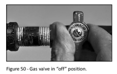
1 Turn the gas control knob on the gas control valve to the OFF position.
2 Turn the manual gas valve for the water heater’s supply line OFF.
3 Open a hot water faucet and let the hot water run until it is cool (This may take 10 minutes or longer).
WARNING! Be sure the water runs out before draining the tank to reduce the risk of scalding.
4 Connect a garden hose to the drain valve and place the other end ofthe hose in a drain outside, or buckets. Note that sediment in the bottom of the tank may clog the vavle and prevent from draining, you cart get the tank to drain, contact a qualified person
5 Turn the cold water supply valve OFF
6 Open the drain valve on the water heater.
7 Also open a hot water faucet to help the water in the tank drain faster.
8 Remove and inspect the anode rod and replace if depleted. The anode rod requires a 1-1/16” socket.
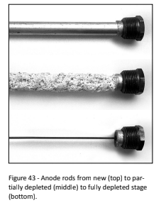
Anode Rod. The anode rod is a sacrificial metal rod that helps avoid corrosion and premature failure (leaks) in the tank. The anode rod is a consumable item. Inspect the anode rod after the first six months of operation when you drain and flush the tank. Replace the anode rod its substantially worn out or depleted. Thereafter. inspect the anode rod annually or more frequently if needed. If you use a water softener, your anode rod will deplete faster than normal. Inspect the anode rod more frequently. replacing the anode rod fit is depleted. Obtain a new anode rod from Lowe's or have a qualified person replace it. (Anode rods are a consumable item and are not covered under warranty).
9 If a large amount of sediment was present when the tank was drained. fish the tank by opening the cold water supply valve and letting the water run until no more sediment drains from the tank. Close the drain valve when you are done.
10 Refill the tank by opening the cold water supply valve. Make sure a hot water faucet is open and the drain valve is closed. Allow a hot water faucet to run full for at least three minutes to make sure the tank has all the air removed and is completely full of water. Once you are certain the tanks completely full of water. close the hot water faucet.
11 Relight the pilot using the instructions on page 23 and adjust the gas control knob to the desired temperature. It may take an hour or more for the tank of cold water to heat up.
Visual Inspection
On an annual basis. visually inspect the venting and air supply system. piping systems. main burner. pilot burner. and the air filter.
Check the water heater for the following:
- Obstructions. damage. or deterioration in the venting system. Make sure the ventilation and combustion air supplies are not obstructed. Check the air filter for dust or other debris and clean if needed.
- Build up of soot and carbon on the main burner and pilot burner. The burner may be cleaned with soap and hot water.
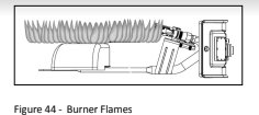
- Inspect the burner flames through the viewport and compare them to the drawing below. A properly operating burner should produce a soft blue flame. Blue tips with yellow inner cones are satisfactory. The tips of the flame may have a light yellow tint. The flame should not be all yellow or have a sharp blue-orange color. Contaminated air may cause an orange-colored flame. Contact a qualified technician if the lame is not satisfactory.
- Leaking or damaged water and gas piping
- Remove any flammable. corrosive cr combustible materials near the water heater.
T&P Relief Valve Maintenance
If you lack the necessary skills required to properly perform this visual inspection or if the burner needs to be cleaned, get help from a qualified person. Read and follow the operating and annual maintenance instructions provided by the manufacturer of the T&P Relief Valve (yellow label attached to T&P Relief Valve). Minerals in the water can form deposits that cause the valve to stick or create blocked passages, making the T&P Relief Valve inoperative.
Follow these guidelines:
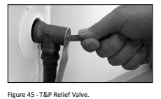
- At least annually. operate the T&P Relief Valve manually to ensure the waterways are clear and the valve mechanism moves freely (above). Before operating the valve manually, check that it will discharge in a place for secure disposal.
WARNING! Hot water will be released. Before operating the T&P relief valve manually. check that it wl discharge in a safe place. If water does not flow freely from the end of the
discharge pipe. turn the gas control knob to the OFF position and call a qualified person to determine the
- At least every five years. have a {qualified person inspect the T&P Relief Valve and discharge pipe. Damage caused by corrosive water conditions. mineral deposits. or other problems can only be determined when a qualified person removes and inspects the valve and its components.
A dripping T&P Relief Valve is usually caused by the home's water pressure being too high or the lack of a Thermal Expansion Tank. If your T&P Relief Valve drips. see page 26.
AT&P relief valve that has been allowed to drip for an appreciable period of time should be inspected for mineral buildup. See T&P relief valve tag for more information.
Inspect and Clean the Air Filter
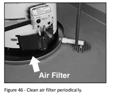
An air filter should be installed around the base of the water heater. At least annually inspect the ar filter and check for a build-up of dust or debris.
Vacuum the filter to remove any dust or debris. fan oily residue is present on the filter, wash it in soap and water. then dry the filter.
Removing and Replacing the Gas Control Valve/Thermostat
IMPORTANT: The gas control valve/thermostat is a standard valve with wire leads that connect to a thermal switch.
Removing the Gas Control Valve/Thermostat:
1 Turn the gas control/temperature knob to the “OFF” on.
2 Turn off the gas at the manual shut-off valve on the gas supply pipe.
3 Drain the water heater. Refer to the “Draining and Flushing the Water Heater” section (see page 28) and follow the procedure.
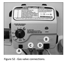
4 Disconnect the A igniter wire from the igniter lead wire. Use needle nose pliers to disconnect the B red (+) and white (-) thermopile wires. Disconnect C pilot tube (7/16" wrench) and D manifold tube (3/4” wrench) at the gas control valve/thermostat. NOTE: L.P. Gas systems use reverse ( -hand) threads on the manifold tube.
5 Disconnect the ground joint union in the gas piping. Disconnect the remaining pipe from the gas control valve/thermostat.
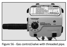
6 To remove the gas control valve/thermostat. thread a 4” section of gas pipe into the inlet and use it to turn the Flame Lock® Safety System Operational Checklist TROUBLESHOOTING CHART gas control valve/thermostat (counterclockwise.)
Do not use pipe wrench or equivalent to grip body. Damage may result. causing leaks. Do not insert any sharp objects into the inlet or outlet connections. Damage to the gas control valve/ thermostat may result.
Replacing Gas Control Valve/Thermostat:
To replace the gas control valve/thermostat. reassemble in reverse order. When. replacing the gas control valve/ thermostat. thread 2.4” section of gas pipe into the inlet and use it to turn the gas control valve/thermostat (clockwise.)
DO NOT OVER-TIGHTEN. damage may result.
- Be sure to use approved Teflon tape or pipe joint compound on the gas piping connections and fitting on the back ofthe gas control valve that screws into tank.
- Be sure to remove the pilot ferrule nut from the new gas control valve/thermostat.
- Tum the gas supply on and check for leaks. Test the water heater by brushing on an approved noncorrosive leak detection solution. Bubbles forming indicate a leak. Correct any leak found.
- Be sure tanks completely filled with water before lighting and activating the water heater. Follow the “Lighting instructions” on page 23.
- If additional information is required. contact the Service Department at: 1-877-817-6750.
REPAIR PARTS
Replacement parts may be ordered through your plumber or the local distributor. Parts will be shipped at prevailing prices and billed accordingly
NOTICE: When ordering replacement parts, have the following informaƟ on ready
- Model and serial number
- Type of gas used
- Item number
- Parts on
Legend
 Special anode rod (see page 26)
 Temperature and Pressure Relief Valve is required but may be factory installed
 Unique: Flame Lock® Safety System parts
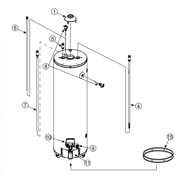
REPAIR PARTS LIST
1 DRAFT HOOD
2 REDUCER RING - SOME MODELS (NOT SHOWN)
3 FLUE BAFFLE (NOT SHOWN)
4 COMBINATION DIP TUBE/HEAT TRAP NIPPLE
5 HEAT TRAP/NIPPLE
6 ANODE ROD - SOME MODELS
7 COMBINATION HEAT TRAP NIPPLE/ANODE - SOME MODELS
8 TEMPERATURE & PRESSURE RELIEF VALVE (LOCATED TOP OR SIDE)
9 DRAIN VALVE
10 GAS CONTROL VALVE/THERMOSTAT (with thermal switch wire lead)
11 OUTER DOOR
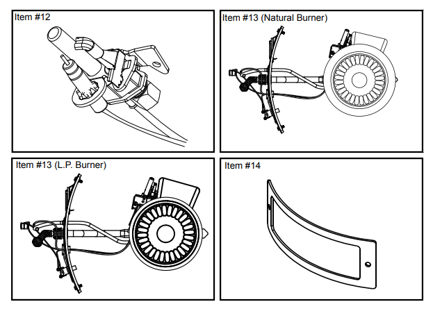
12 PILOT/THERMOPILE ASSEMBLY KIT
13 FINAL BURNER ASSEMBLY
14 MANIFOLD DOOR GASKET
15 WRAP AROUND AIR FILTER
Listed Parts Kits and Illustrations
Item 12: Pilot assembly kit, which contains the pilot assembly, thermopile, and retainer clip (Natural Gas or L.P.)
Item 13: Final burner assembly which contains the burner, orifice, manifold tube, gasket, door, pilot tube, thermopile, manifold component block with retainer clip, thermal switch, and pilot assembly. (Natural Gas/Low Nox or L.P.)
Item 14: Contains manifold door gasket