Before driving
Introduction 2
Instrumentation 5
Controls and features 18
Seating and safety restraints 53
Starting and driving
Starting 83
Driving 91
Roadside emergencies 135
Servicing
Maintenance and care 154
Capacities and specifications 213
Reporting safety defects 220
Index 221
Contents
1
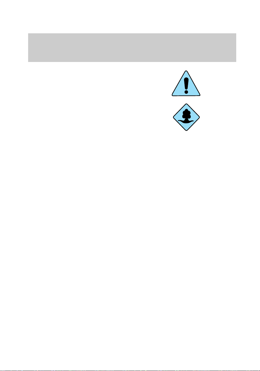
ICONS
Indicates a warning. Read the
following section on Warnings for
a full explanation of them.
Indicates that vehicle information
related to recycling and other
environmental concerns will follow.
We must all play our part in
protecting the environment.
Correct vehicle usage and the
authorized disposal of waste
cleaning and lubrication materials
are significant steps towards this
aim.
WARNINGS
How can you reduce the risk of
personal injury and prevent
possible damage to others, your
vehicle and its equipment?
In this owner’s guide, answers to
such questions are contained in
comments highlighted by the
warning triangle symbol.
BREAKING-IN YOUR VEHICLE
There are no particular breaking-in
rules for your vehicle. Simply avoid
driving too briskly during the first
1,600 km (1,000 miles) of driving.
Vary speeds frequently. This is
necessary to give the moving parts
a chance to break in.
If possible, you should avoid full
use of the brakes for the first
1,600 km (1,000 miles).
From 1,600 km (1,000 miles)
onwards you can gradually
com_icons.01
com_warn.01
com_breaking_vehicle.01
Introduction
2

increase the performance of your
vehicle up to the permitted
maximum speeds.
INFORMATION ABOUT THIS
GUIDE
The information found in this
guide was in effect at the time of
printing. Ford may change the
contents without notice and
without incurring obligation.
Notice to owners of utility type
vehicles
Before you drive your vehicle,
please read this Owner’s Guide
carefully. Your vehicle is not a
passenger car. As with other
vehicles of this type, failure to
operate this vehicle correctly may
result in loss of control or an
accident.
Be sure to read Driving off road
in the Driving chapter as well as
the “Four Wheeling” supplement
included with 4WD and utility type
vehicles.
Using your vehicle with a
snowplow
For more information and
guidelines for using your vehicle
with a snowplow, refer to the
Driving chapter.
Using your light truck as an
ambulance
Do not use this vehicle as
an ambulance.
com_info_guide.01
f12_utility_notice
f12_snowplowing
f12_no_ambulance
Introduction
3

Your vehicle is not equipped with
the Ford Ambulance Preparation
package.
Introduction
4
3
50
30
70
40
80
120
140
40
20
90
60
80
60
100
20 km/h
000005
2
4
5
6
1
L
H
E
F
3
50
30
70
40
80
120
140
40
20
90
60
80
60
100
20 km/h
000005
2
4
5
6
1
L
H
E
F
P
ON
OFF
RES
SET
ACCEL
COAST
INT 2
INT 1
OFF
OVERDRIVE OFF
PANEL
DIM
AUTO
LAMP
C
H
8
18
C
H
8
18
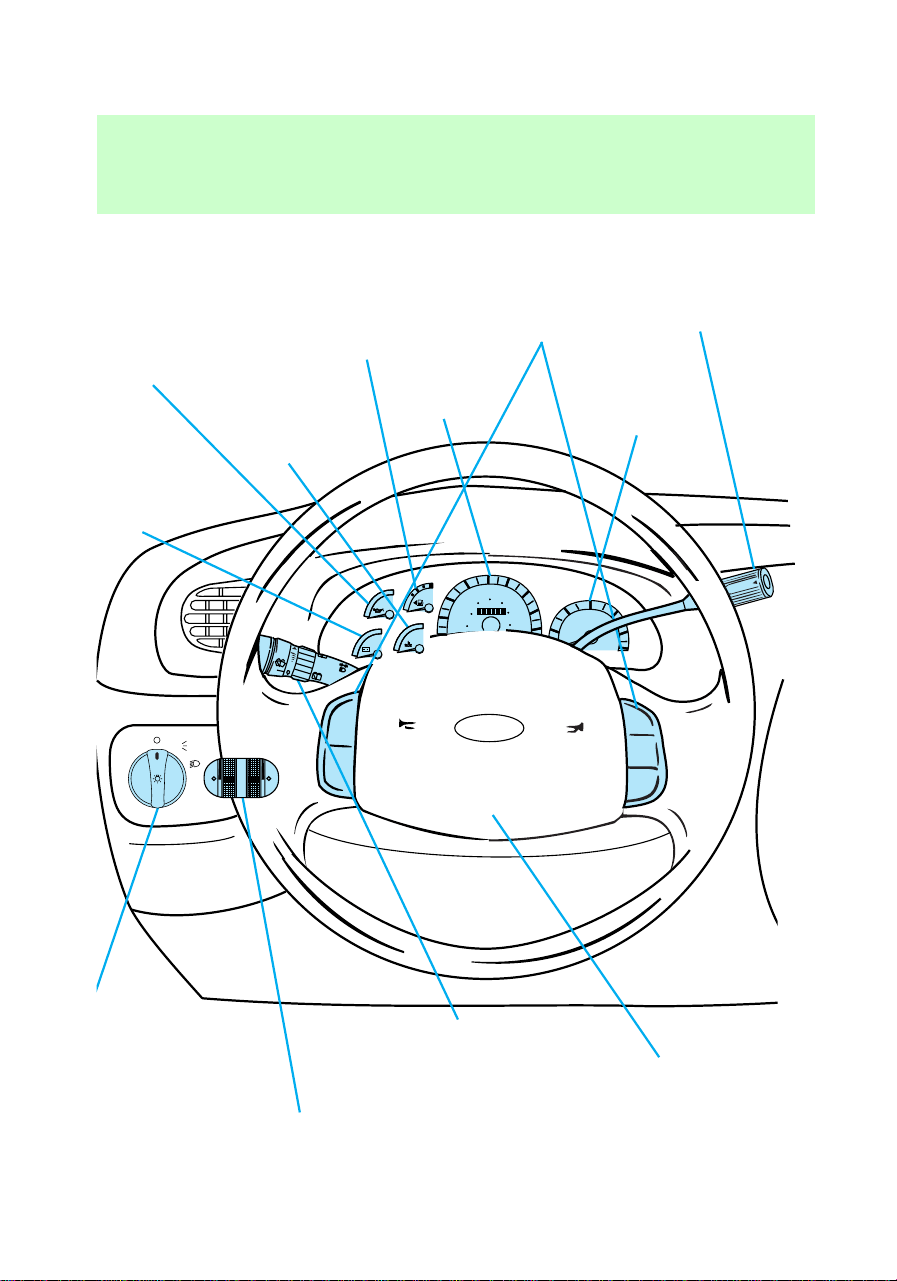
SRS
Charging
system
gauge
(pg. 16)
Engine oil
pressure gauge
(pg. 16)
Engine
coolant
temperature
gauge
(pg. 15)
Fuel gauge
(pg. 15)
Speedometer
(pg. 14)
Speed control*
(pg. 33)
Tachometer*
(pg. 15)
Transmission
control switch
(pg. 38)
Driver air bag
(pg. 66)
Turn signal and
wiper/washer control
(pg. 36)
Instrument panel
dimmer switch
(pg. 20)
Headlamp
control
(pg. 18)
Instrumentation
6
REW
1
FF
2
SIDE 1-2
3
FM 1
ST
VOL – PUSH ON
AM
FM
BASSTREB
BAL FADE
AUTO
SET
CLK
SEEK
TUNE
DISCS
SCAN
4
DOLBY SYSTEM
EJ
TAPE CD
COMP
5
SHUFFLE
6
WARMCOOL
FLR
& DEF
*MAX
A/C
FLOOR
PANEL &
FLOOR
DEF
OFF
PANEL
*A/C
LO
HI
PASSENGER AIRBAG
ON
OFF
OFF
2H
4H
4L
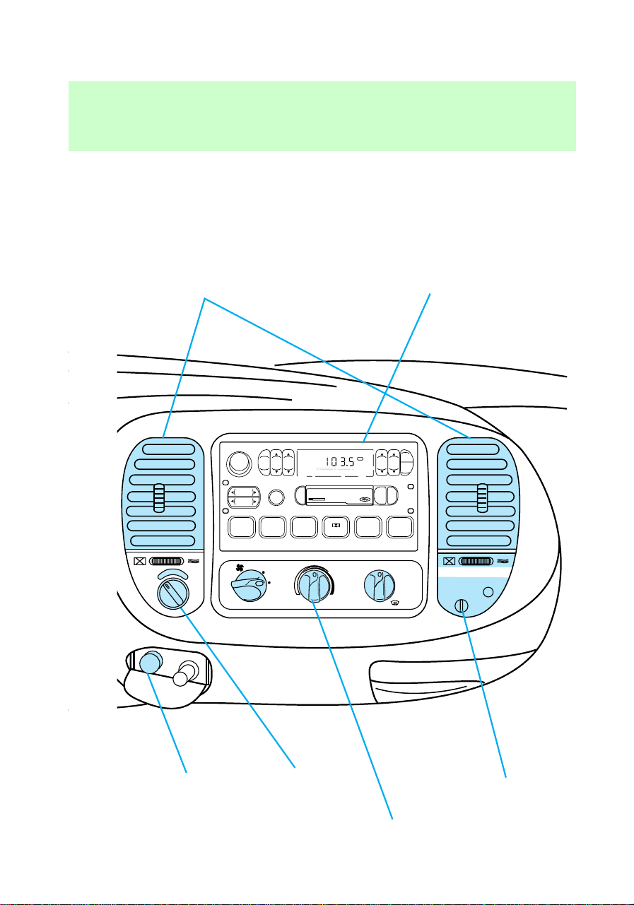
Vents
(pg. 25)
Electronic sound system
(pg. 22)
Passenger air
bag deactivate
switch
(pg. 71)
Climate
controls
(pg. 25)
4WD Control*
(pg. 110)
Auxiliary
power point
(pg. 22)
* if equipped
f12_inst_warn_lights
Instrumentation
7
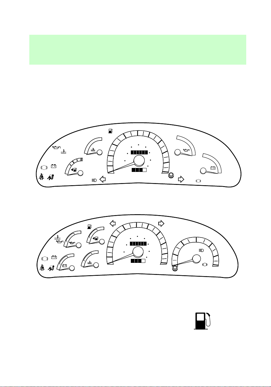
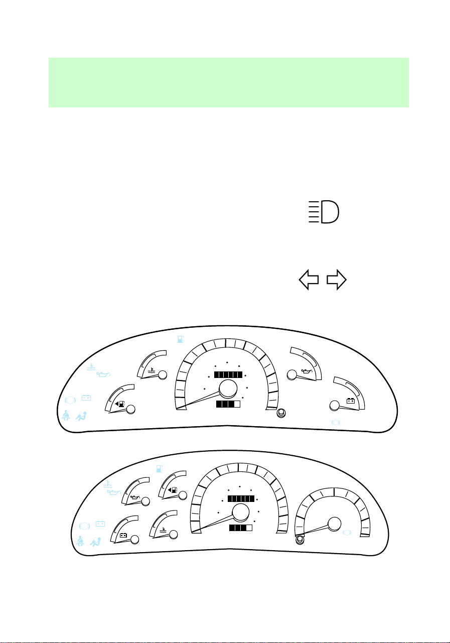
INSTRUMENT CLUSTER
WARNING LIGHTS AND
CHIMES
Your vehicle is equipped with one
of the following instrument
clusters:
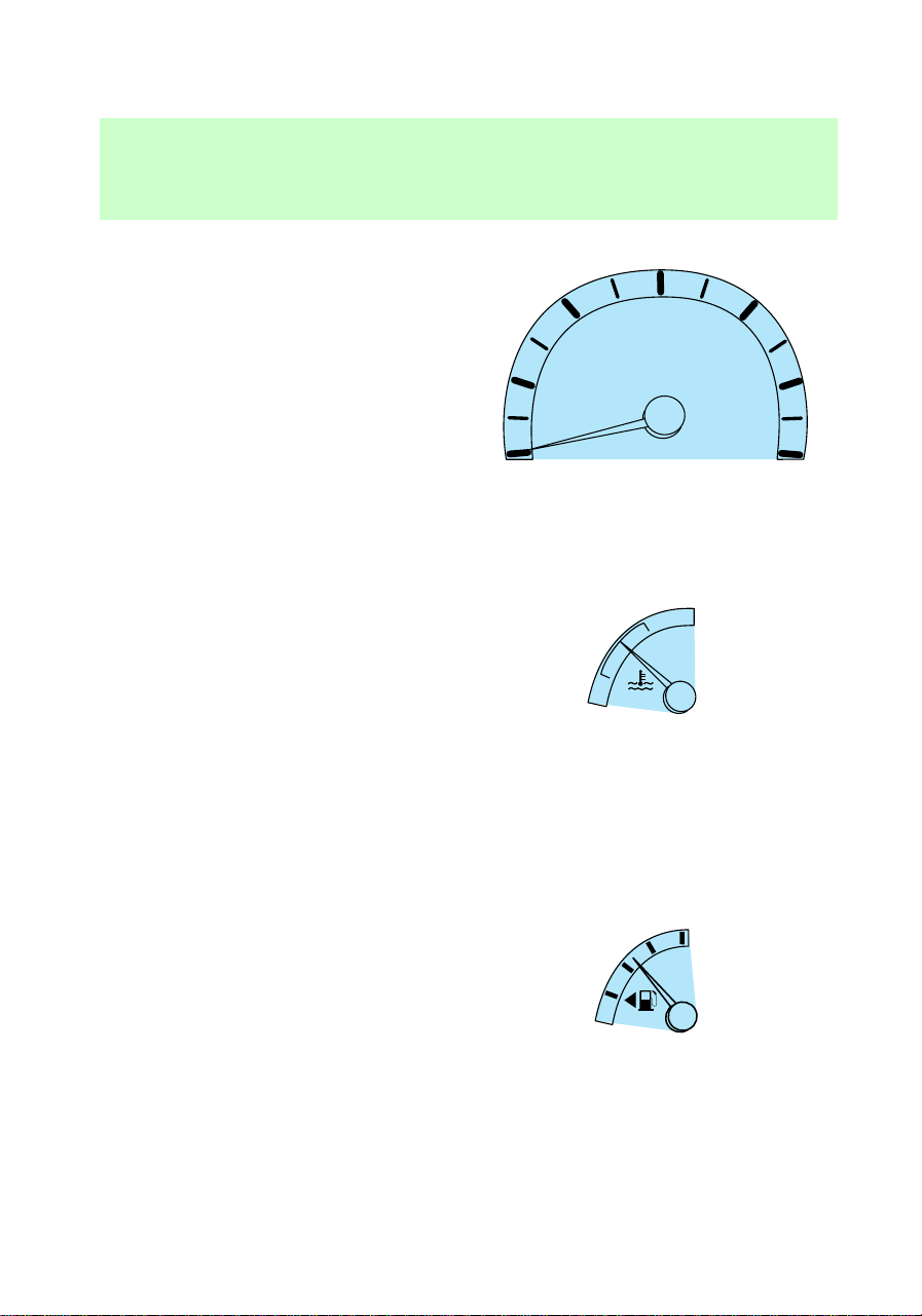
Low fuel
Illuminates when the fuel level is
low.
MPH
10
50
30
70
40
80
120
140
180
40
20
0
100
90
60
80
60
100
20 km/h
0010
000005
C
H
E
F
LOW
RANGE
DOOR
AJAR
LOW
FUEL
MPH
10
50
30
70
40
80
120
140
180
40
20
0
100
90
60
80
60
100
20 km/h
0010
000005
C
H
E
F
LOW
RANGE
4x4
FUEL
RESET
CHECK
ENGINE
ABS
DOOR
AJAR
LOW
FUEL
L
H
18
8
!
BRAKE
3
10
50
30
70
40
80
120
140
40
20
0
100
90
60
80
60
100
20 km/h
0010
000005
2
4
5
6
0
1
L
H
C
H
E
F
8
18
THEFT
RPMx1000
LOW
RANGE
4x4
FUEL
RESET
CHECK
ENGINE
ABS
DOOR
AJAR
LOW
FUEL
3
10
50
30
70
40
80
120
140
40
20
0
100
90
60
80
60
100
20 km/h
0010
000005
2
4
5
6
0
1
L
H
C
H
E
F
8
18
THEFT
RPMx1000
ABS
BRAKE
LOW
FUEL
!
LOW
FUEL
f12_low_fuel
f12_eng_cool_temp
Instrumentation
8

Engine coolant temperature
Illuminates briefly when the
ignition key is turned to On (light
from optional cluster shown).
Illuminates when the engine
coolant temperature is high. Stop
the engine and check the engine
coolant temperature level as soon
as possible. Refer to Checking
and adding engine coolant and
What you should know about
fail-safe cooling in the
Maintenance and care section.
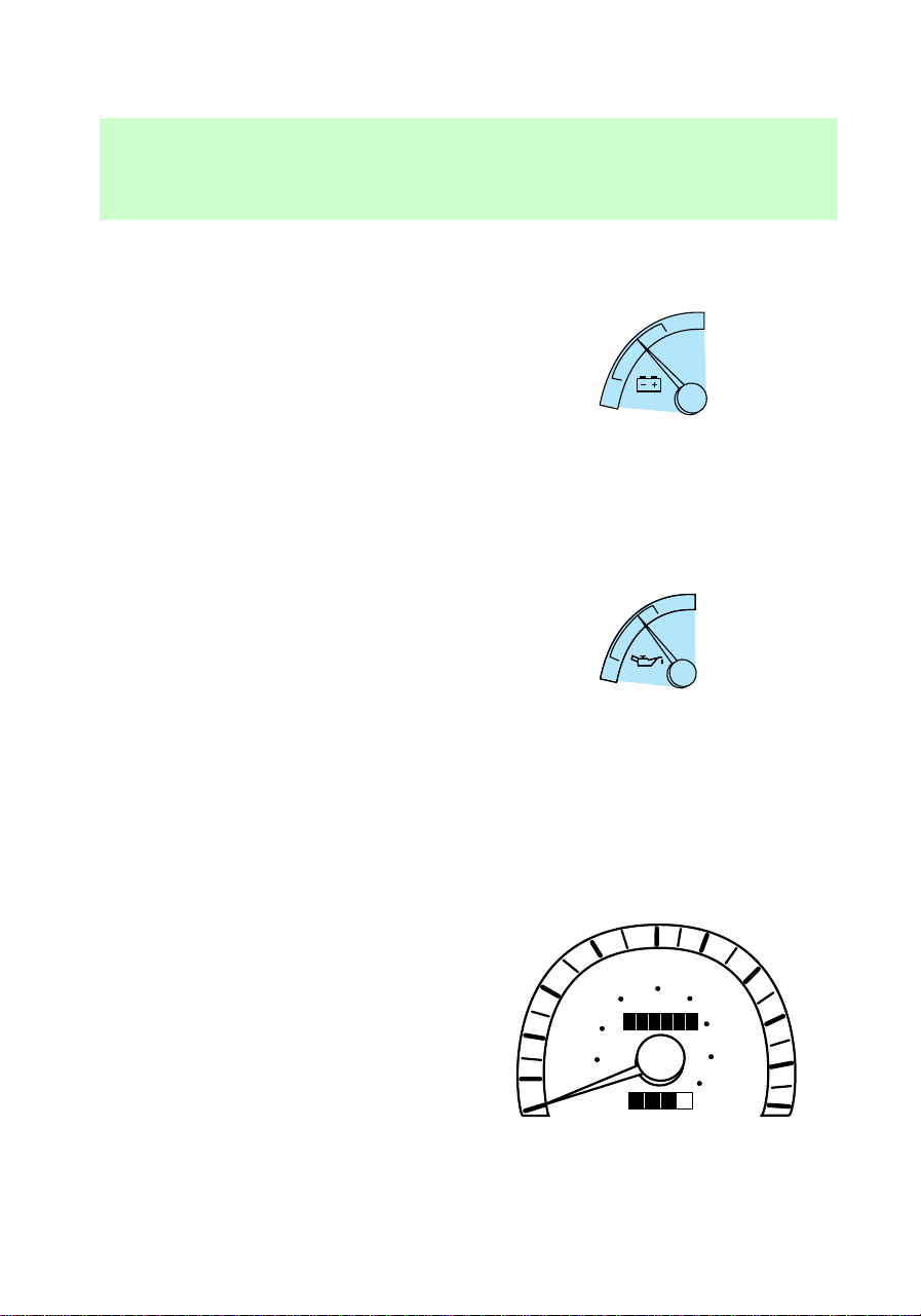
Oil pressure
Illuminates briefly when the
ignition key is turned to On (light
from base cluster shown).
Illuminates when the oil pressure
is low. Stop the engine and check
the engine oil level as soon as
possible. Refer to Checking and
adding engine oil in the
Maintenance and care section.
Door ajar
Illuminates when the ignition
switch is in the ON or START
position and any door is open.
Charging system
Briefly illuminates when the
ignition is turned on and the
engine is off. The light also
illuminates when the battery is not
charging properly, requiring
electrical system service.
DOOR
AJAR
f12_oil_pressure
com_door-ajar.02
com_charging_system.01
com_brake_system.01
Instrumentation
9
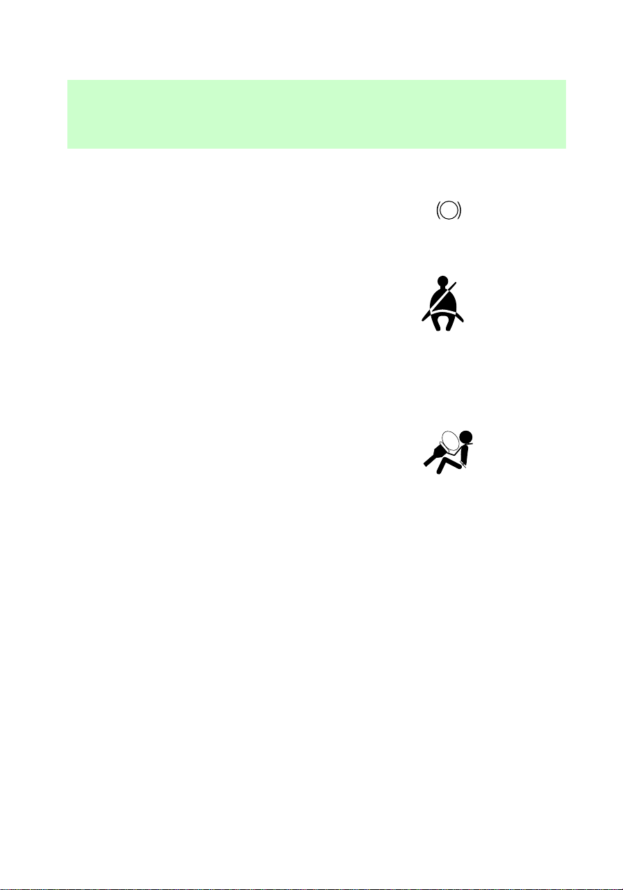
Brake system warning
Extinguishes when the parking
brake is released. Illumination after
releasing the parking brake
indicates low brake fluid level.
Safety belt
Illuminates when the ignition is
switched on to remind you to
fasten your safety belts. For more
information, refer to Using the
safety restraints properly in the
Seating and safety restraints
chapter.
Air bag readiness
Briefly illuminates when the
ignition is turned to On. If the light
fails to illuminate, continues to
flash or remains on, have the
system serviced. For more
information, refer to
Supplemental restraints system
(SRS) in the Seating and safety
restraints chapter.
Check engine warning light
This light illuminates when the
engine’s Emission Control System
requires service. It will also
illuminate when the ignition key is
in the On position and the engine
is off. Refer to What you should
know about the on-board
diagnostic (OBD II) system in the
Maintenance and care chapter.
!
BRAKE
CHECK
ENGINE
com_safety_belt.01
f12_air_bag_readiness
f12_check_engine
f12_tcil_light
Instrumentation
10
Transmission control indicator
light (TCIL)
The TCIL (OFF), located on the
end of the gearshift lever, may
flash steadily if a malfunction has
been detected. If the TCIL is
flashing, contact your Ford dealer
as soon as possible. If this
condition persists, damage to the
transmission could occur.
For more information, refer to the
Driving chapter.
4x4 light (if equipped)
Illuminates when 4H (Four-Wheel
Drive) or 4L (Four-Wheel Drive
Low) is engaged.
4x4 low range (if equipped)
Illuminates when 4L (Four-Wheel
Drive Low) is engaged.
Anti-lock brake system (ABS)
Momentarily illuminates when the
ignition is turned on and the
engine is off. If the light stays on
or continues to flash, the ABS
needs to be serviced.
Fuel reset
Illuminates when the ignition key
is turned to the ON position and
the fuel pump shut-off switch has
been triggered. For more
information, refer to Fuel pump
shut-off switch in the Roadside
emergencies chapter.
OVERDRIVE OFF
4x4
LOW
RANGE
ABS
FUEL
RESET
f12_4x4_light
f12_4x4_low
com_anti-lock_brake.01
com_fuel_reset.01
com_anti-theft_alarm.01
Instrumentation
11
Anti-theft system (if equipped)
Illuminates when the anti-theft
system is arming and flashes when
the anti-theft system is armed.
High beams
Illuminates when the headlamp
high beams are on.
Turn signal
Illuminates when the left or right
turn signal or the hazard lights are
turned on.
Testing warning lights
Turn the ignition key to On
without starting the vehicle. The
THEFT
!
MPH
10
50
30
70
40
80
120
140
180
40
20
0
100
90
60
80
60
100
20 km/h
0010
000005
C
H
E
F
DOOR
AJAR
LOW
FUEL
MPH
CHECK
ENGINE
ABS
L
H
18
8
BRAKE
!
LOW
FUEL
ABS
BRAKE
3
MPH
10
50
30
70
40
80
120
140
180
40
20
0
100
90
60
80
60
100
20 km/h
0010
000005
2
4
5
6
0
1
L
H
C
H
E
F
8
18
RPMx1000
CHECK
ENGINE
com_high_beams.01
com_turn_signal.01
f12_testing_lights
Instrumentation
12

warning and indicator lights shown
above will illiminate for a brief
time. If any of these lights do not
illuminate, contact your dealer for
service.
Headlamps on warning chime
Sounds when the headlamps are
on, the key is out of the ignition
and any door is opened.
Key-in-ignition warning chime
Sounds when the key is left in the
ignition and any door is opened.
The chime is not active when the
ignition key is in the On position.
Safety belt warning chime
For information on the safety belt
warning chime, refer to the
Seating and safety restraints
chapter.
Supplemental restraint system
(SRS) warning chime
For information on the SRS
warning chime, refer to the
Seating and safety restraints
chapter.
f12_headlamps_on
f12_key_in_ignition
com_safety_chime.01
com_srs_chime.01
f12_gauges
Instrumentation
13
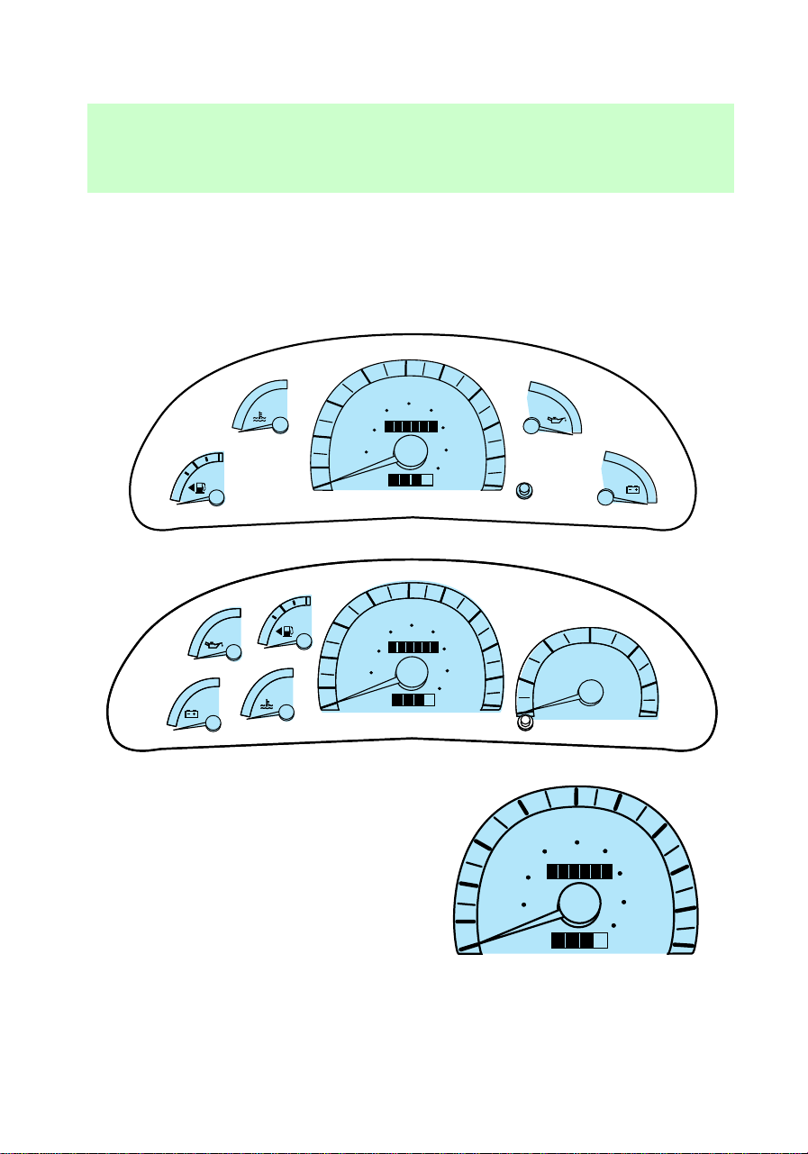
INSTRUMENT CLUSTER
GAUGES
Your vehicle has one of the
following instrument clusters:
Speedometer
Indicates the current vehicle road
speed.
10
50
30
70
40
80
120
140
180
40
20
0
100
90
60
80
60
100
20 km/h
0010
000005
L
H
C
H
18
8
E
F
E
F
3
10
50
30
70
40
80
120
140
180
40
20
0
100
90
60
80
60
100
20 km/h
0010
2
4
5
6
0
1
L
H
C
H
E
F
8
18
THEFT
RPMx1000
3
MPH
10
50
30
70
40
80
120
140
180
40
20
0
100
90
60
80
60
100
20 km/h
0010
000005
2
4
5
6
0
1
L
H
C
H
E
F
8
18
THEFT
RPMx1000
MPH
50
40
80
120
140
180
40
60
100
20 km/h
0010
000005
MPH
10
50
30
70
40
80
120
140
180
40
20
0
100
90
60
80
60
100
20 km/h
0010
000005
f12_speedometer
com_tachometer.02
Instrumentation
14
Tachometer (if equipped)
Indicates the engine speed in
revolutions per minute.
Engine coolant temperature
gauge
Indicates the temperature of the
engine coolant. At normal
operating temperature, the needle
remains within the normal area. If
it enters the red section, the
engine is overheating. Switch off
the ignition and let it cool. Refer to
Checking and adding engine
coolant or What you should know
about fail safe cooling in the
Maintenance and care chapter.
Fuel gauge
Indicates the fuel level.
0
RPMx1000
3
2
4
5
6
1
C
H
C
H
E
F
f12_engine_coolant
f12_fuel_gauge
f12_voltage_gauge
Instrumentation
15
Voltage gauge
If the pointer moves and stays
outside of the normal range, it
indicates that the battery is not
being charged. Have the vehicle’s
electrical system checked by your
dealer as soon as possible.
Engine oil pressure gauge
This shows the engine oil pressure
in the system. Sufficient pressure
exists as long as the needle
remains in the normal range. If the
gauge indicates constantly low
pressure at normal engine speed,
refer to Checking and adding
engine oil in the Maintenance
and care chapter. If the gauge
indicates a low pressure and the
engine oil level is correct, switch
off the engine immediately and
have your vehicle checked at your
dealer.
Odometer
Registers the total kilometers
(mileage) of the vehicle.
8
18
8
18
L
H
L
H
MPH
50
40
80
120
140
180
40
60
100
20 km/h
0010
000005
MPH
10
50
30
70
40
80
120
140
180
40
20
0
100
90
60
80
60
100
20 km/h
0010
0
0
0
0
0
0
0
0
0
0
5
5
f12_oil_pressure
f12_odometer
f12_trip_odometer
Instrumentation
16
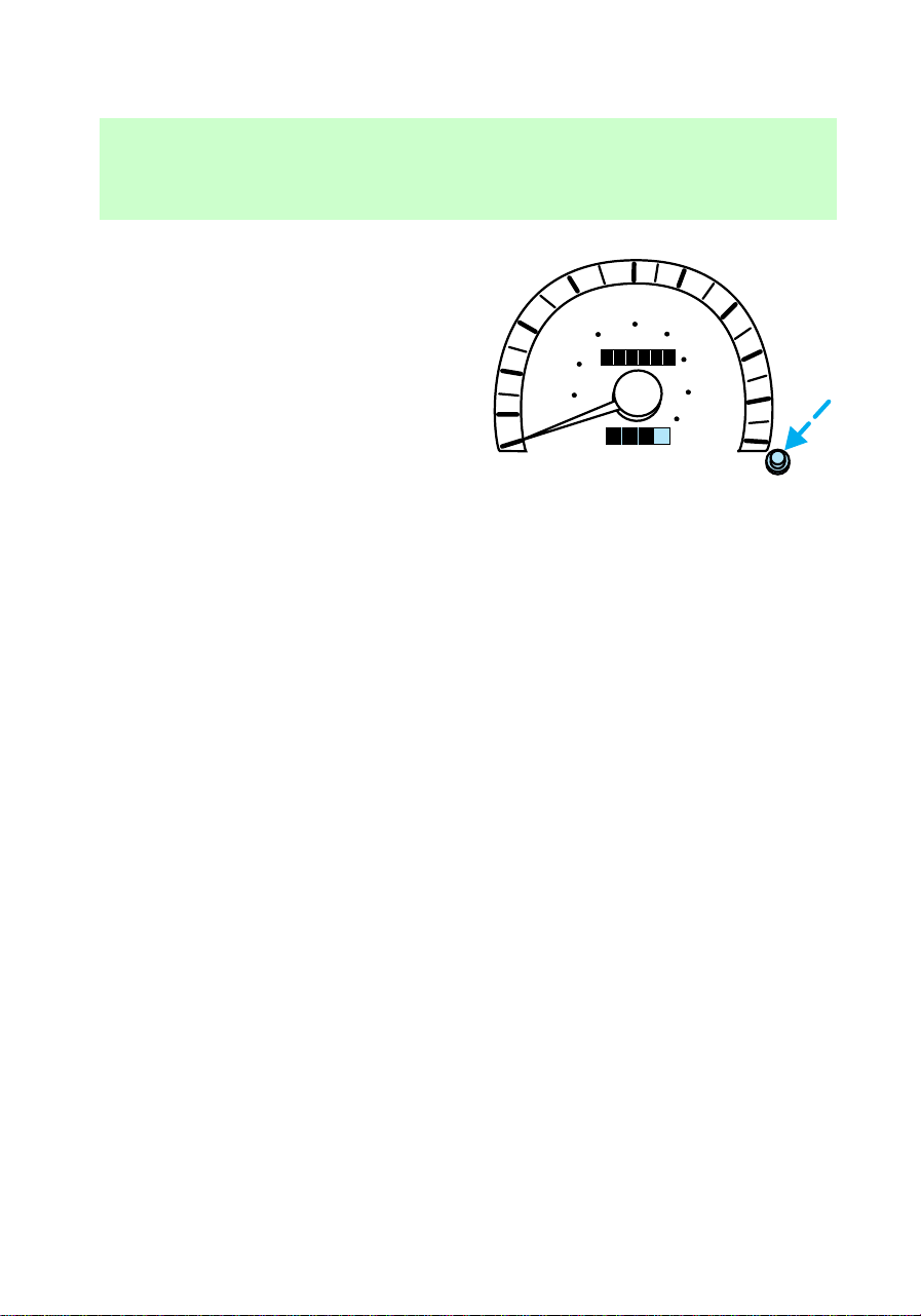
Trip odometer
Registers the kilometers (miles) of
individual journeys. To reset,
depress the control.
MPH
50
40
80
120
140
180
40
60
100
20 km/h
0010
000005
MPH
10
50
30
70
40
80
120
140
180
40
20
0
100
90
60
80
60
100
20 km/h
0
000005
001
Instrumentation
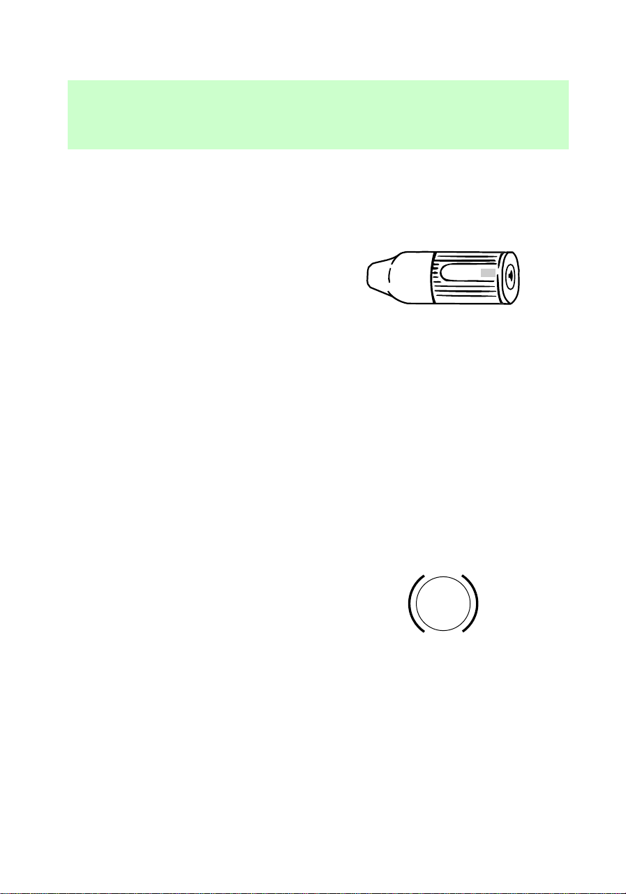
17
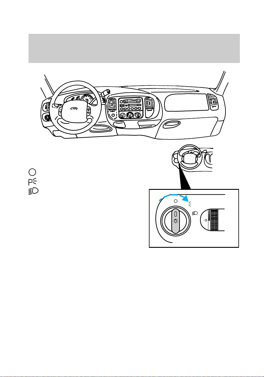
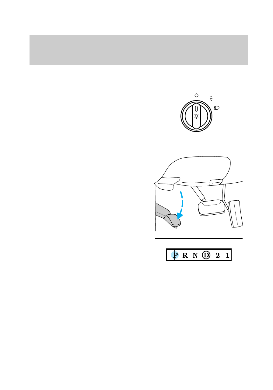
Headlamp/foglamp control
This control operates the
headlamps and foglamps.
— Off
— Parking lamps on.
— Headlamps on.
P
PANEL
DIM
f12_headlamp_switch
f12_foglamp_switch
Controls and features
18
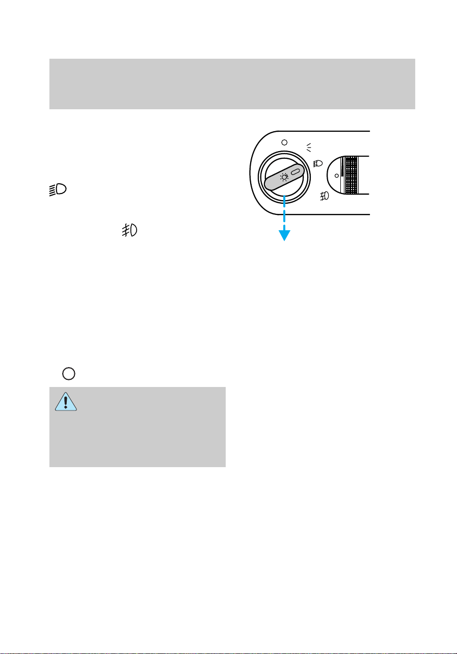
Foglamp control
The headlamp control also
operates the foglamps. The
foglamps can be turned on only
when the headlamps are in the
position.
Pull headlamp control towards you
to turn foglamps on. The foglamp
indicator light
(located to the
right of the control) will illuminate.
Daytime running lights
(Canadian vehicles only)
The daytime running light system
turns the headlamps on, with a
reduced light output, when:
• the vehicle is running
• the parking brake is released
• the headlamp system is in the
position.
The Daytime Running
Light (DRL) system will
not illuminate the tail lamps and
parking lamps. Turn on your
headlamps at dusk. Failure to do
so may result in a collision.
P
PANEL
DIM
f12_drl_lights
f12_dimmer_dial
Controls and features
19
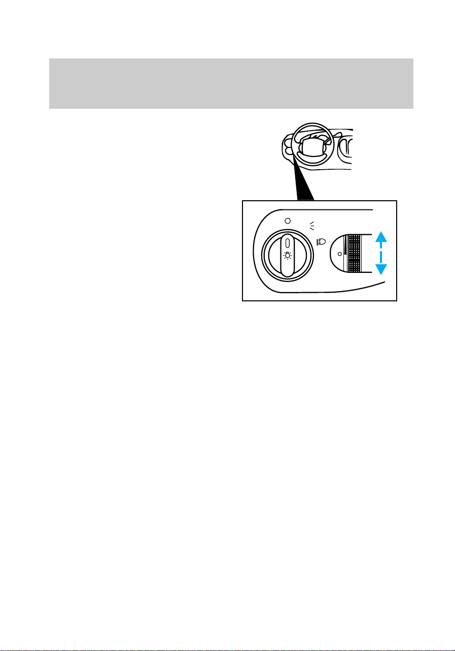
Panel dimmer control
Turn control up to brighten panel.
Turn control down to dim panel.
Autolamp delay system (if
equipped)
The autolamp delay system sets
the headlamp to turn on and off
automatically. You can set the
autolamp to:
• turn on the exterior lamps
automatically at night.
• turn off the lamps automatically
during daylight.
• keep the lamps on for up to
P
PANEL
DIM
f12_autolamp
Controls and features
20
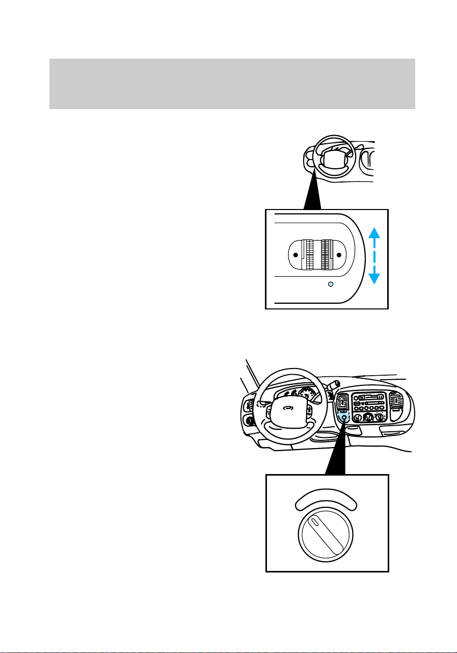
three minutes after you turn the
key to OFF.
1. Turn control up to increase
delay. The indicator light under the
autolamp control illuminates when
the autolamps are activated.
2. Turn control down to decrease
delay.
To turn autolamp system off, turn
control down all the way until a
click is felt.
Electronic shift 4WD system (if
equipped)
This controls the Electronic Shift
4WD operation. Refer to
Electronic Shift 4WD system in
the Driving chapter for more
information.
PANEL
DIM
AUTO
LAMP
2H
4H
4L
f12_4wd_switch
f12_power_point
Controls and features
21
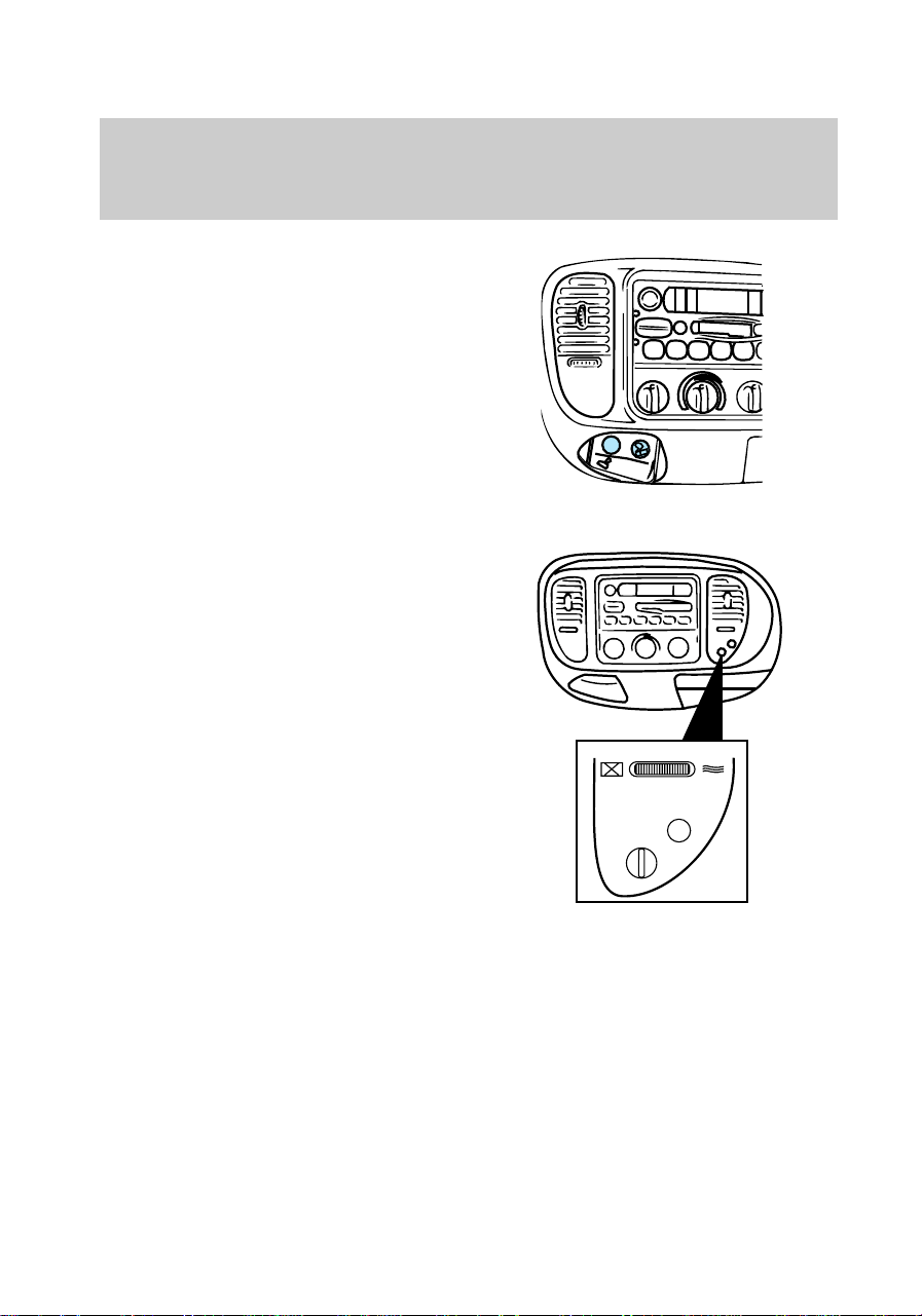
Auxiliary power point
This 12V power point is an
additional power source for
electrical accessories.
Do not plug optional electrical
accessories into the cigarette
lighter. Use the power point.
Passenger air bag deactivate
switch
This switch must be used to
deactivate the passenger air bag
whenever a child seat is used in
the right front or center front
passenger seat position. Refer to
Passenger air bag deactivate
switch in the Seating and safety
restraints chapter.
Audio system
Refer to the “Audio Guide” in your
Owner’s Portfolio.
PASSENGER AIRBAG
ON
OFF
OFF
f12_pass_srs_deact
f12_audio
f12_fuel_shutoff
Controls and features
22
Fuel pump shut-off switch
Refer to the Roadside
emergencies chapter for
information on operating the fuel
pump shut-off switch.
f12_air_suspension
Controls and features
23
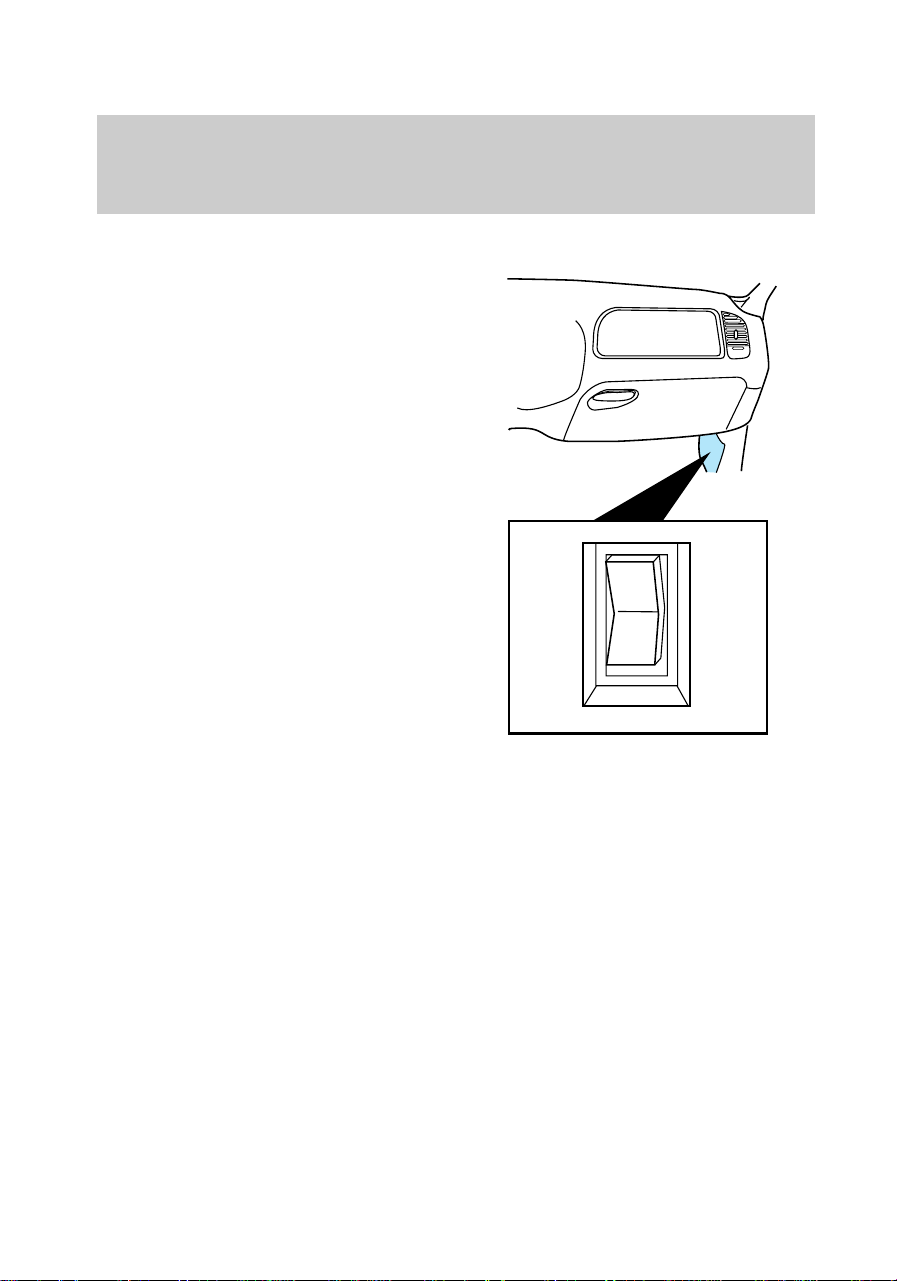
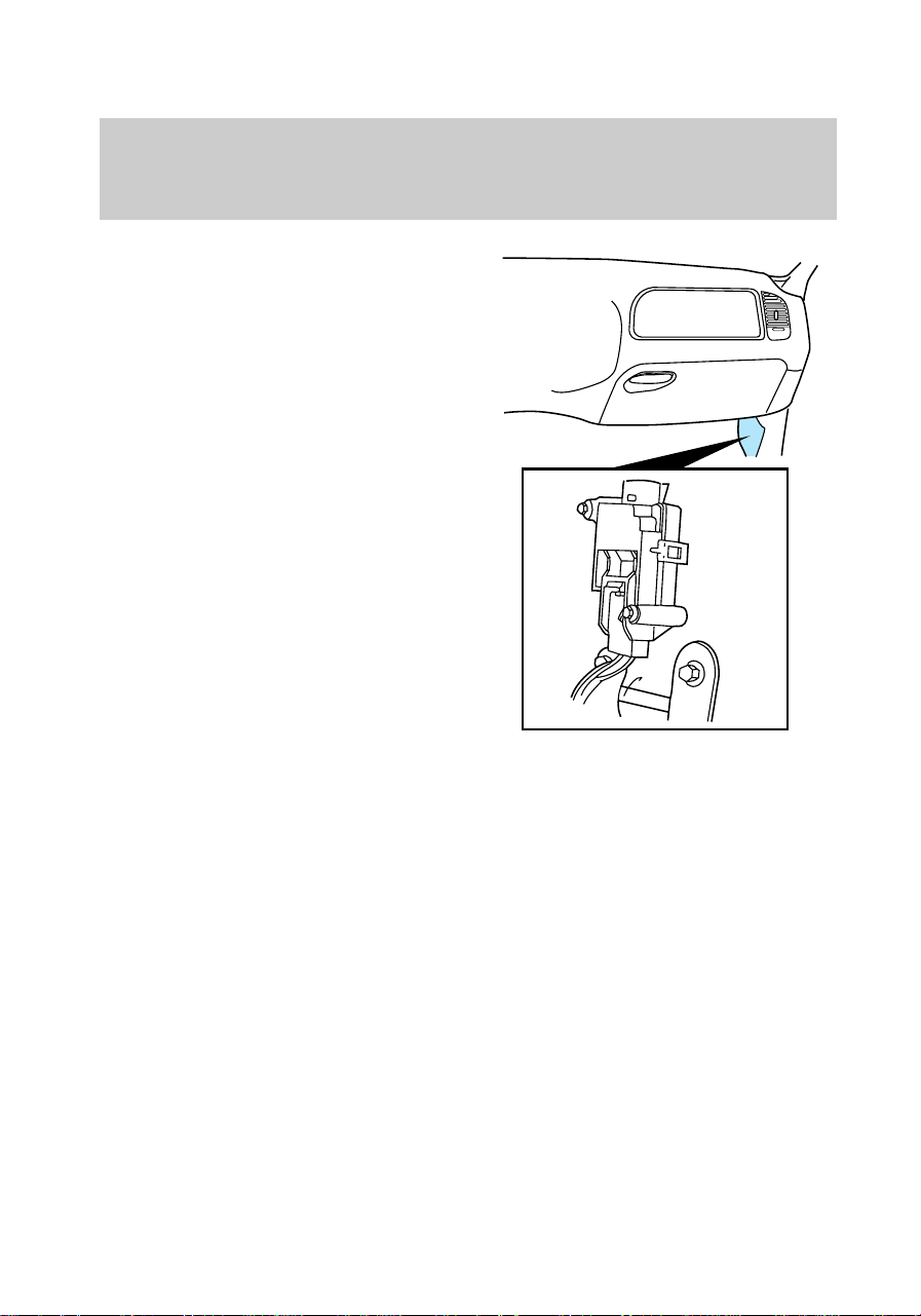
Air suspension load leveling (if
equipped)
Your vehicle is equipped with an
air suspension system for the rear
suspension that levels your vehicle
when carrying heavy loads. Refer
to Air suspension load leveling
in the Driving chapter for more
information.
OFF
f12_climate_controls
Controls and features
24
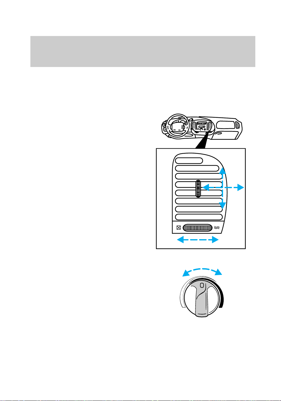
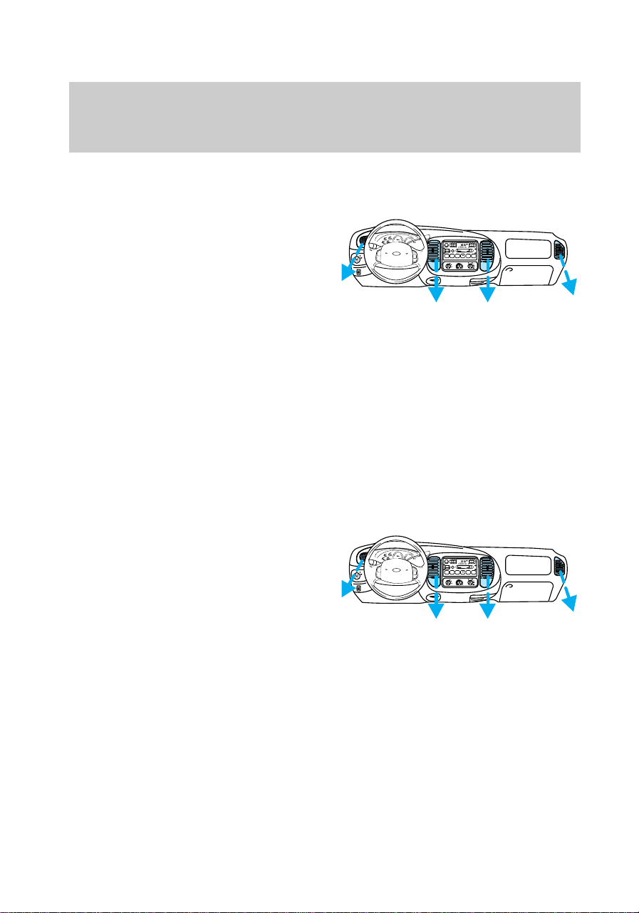
CLIMATE CONTROLS
Operating climate controls
Instrument panel vents
There are four vents on the
instrument panel. These vents are
equipped with controls to adjust
the amount and direction of air
passing through them.
Temperature
Turn temperature control to the
desired temperature.
WARMCOOL
f12_climate_controls
f12_ip_vents
f12_temperature
f12_fan_speed
Controls and features
25
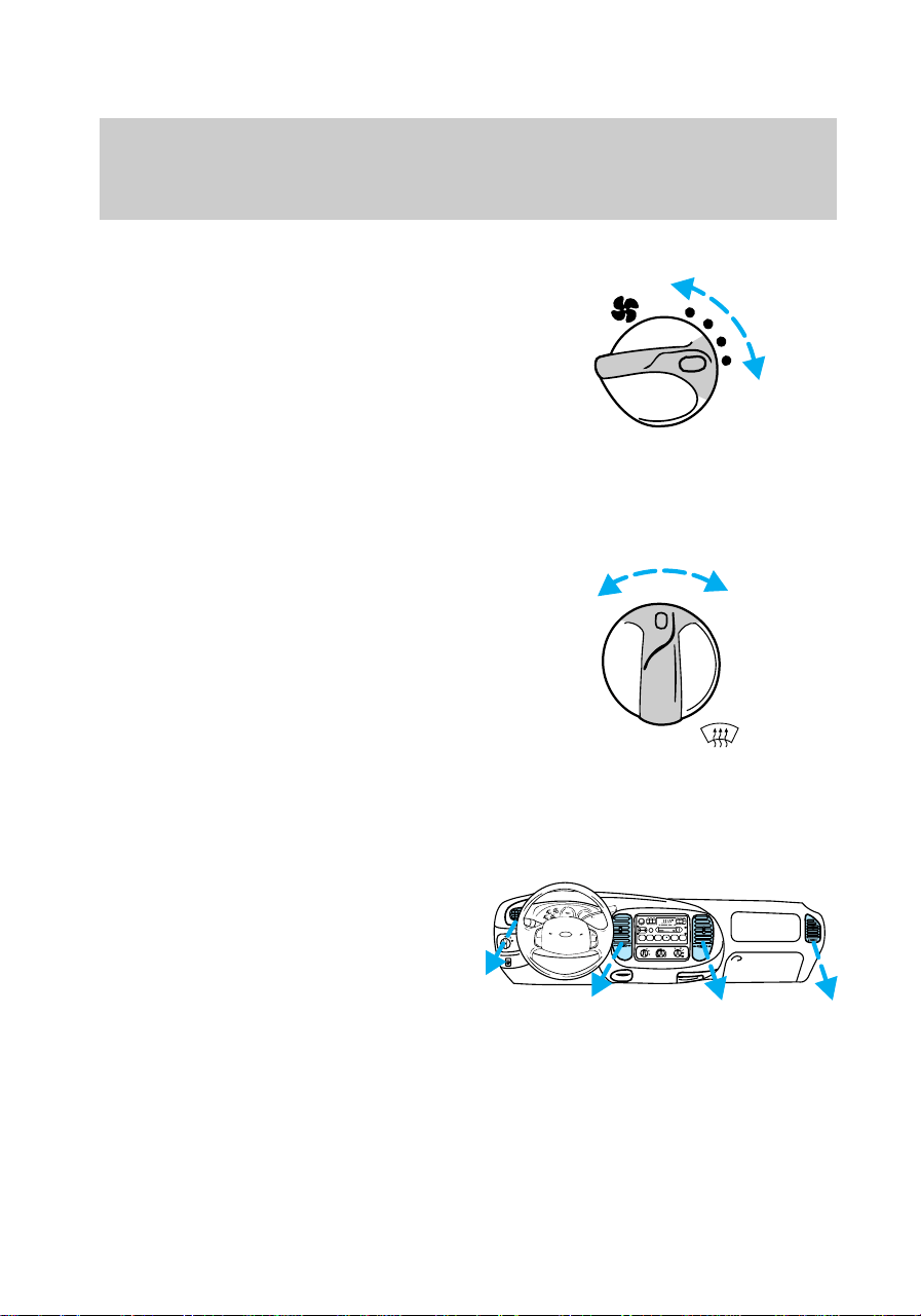
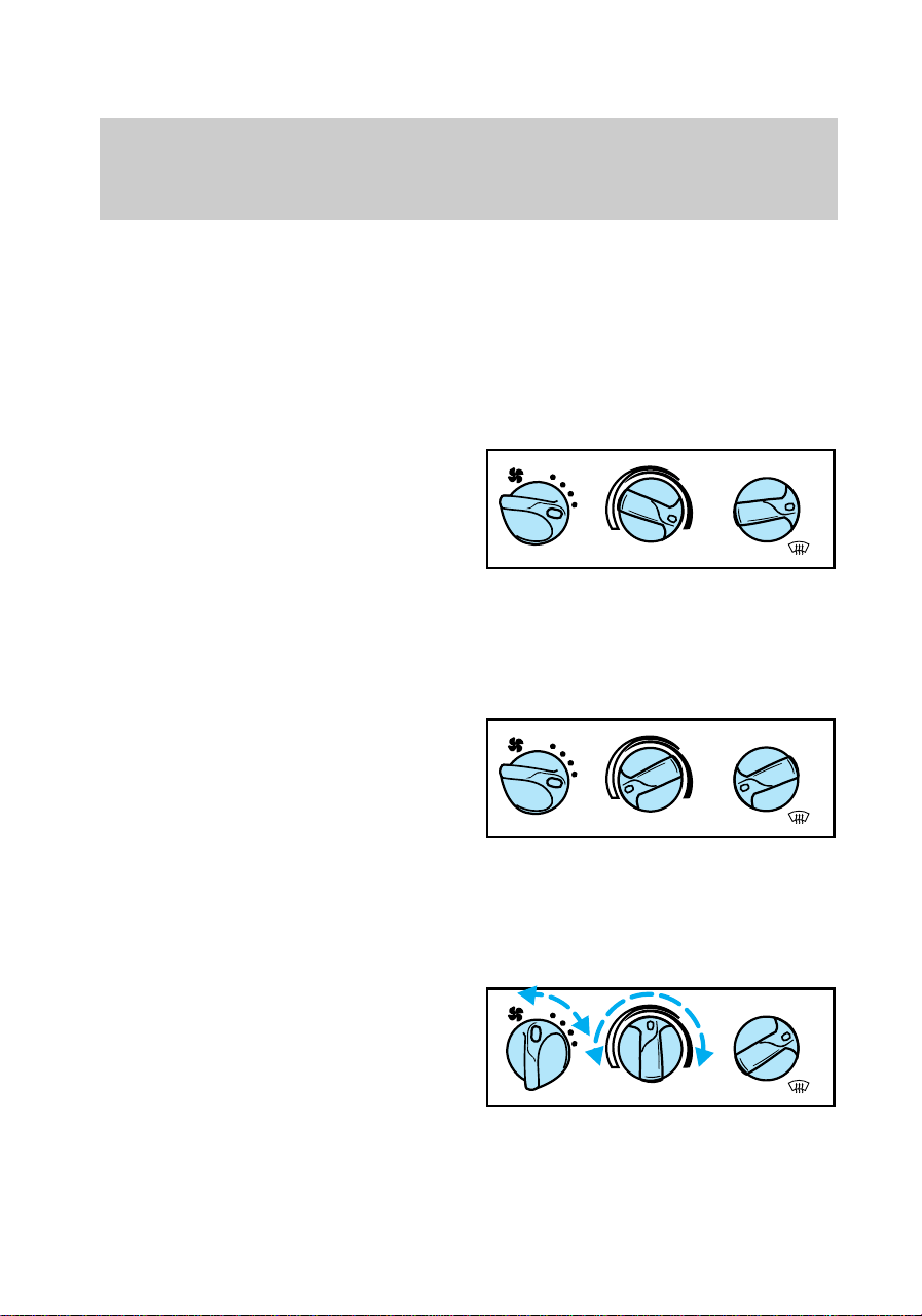
Fan speed
Turn the fan speed control to the
desired speed.
Airflow and air conditioning (if
equipped)
Turn the mode control to the
desired airflow position.
Controlling airflow
Select PANEL for air to flow
through these vents:
LO
HI
FLR
& DEF
MAX
A/C
FLOOR
PANEL &
FLOOR
DEF
OFF
PANEL
A/C
P
HI
LO
OFF
*
A/C
*
MAX
A/C
REW
1
FF
2
SIDE 1-2
3
FM 1
ST
VOL – PUSH ON
AM
FM
BASSTREB
BAL FADE
AUTO
SET
CLK
SEEK
TUNE
DISCS
SCAN
4
DOLBY SYSTEM
EJ
TAPE CD
COMP
5
SHUFFLE
6
f12_mode_control
f12_airflow
Controls and features
26
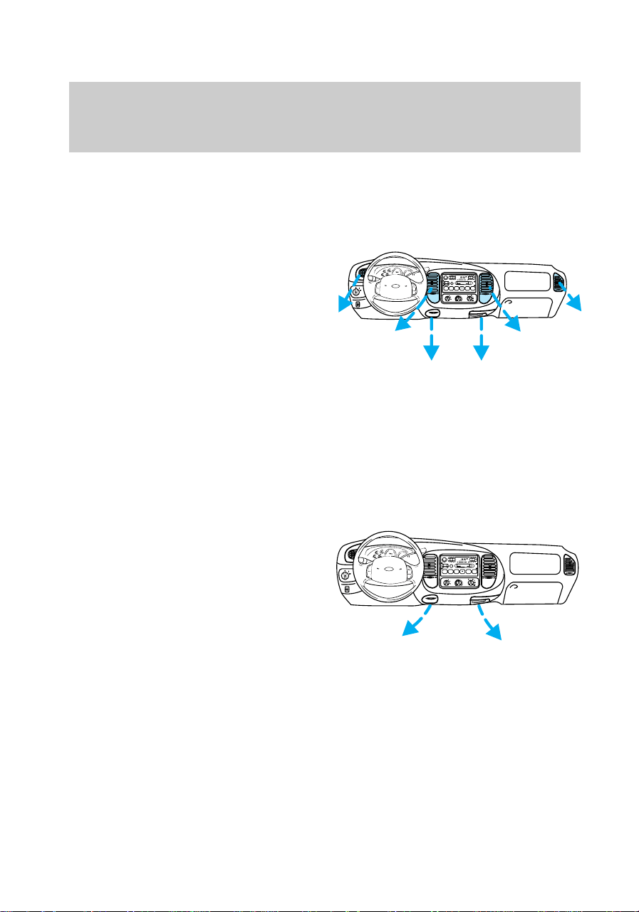
The PANEL position allows outside
air to flow through the instrument
panel vents.
Select PANEL & FLOOR for air to
flow through these vents:
The PANEL & FLOOR position
directs outside air to flow between
the panel and floor vents. The air
conditioning will function to
provide cooling and
dehumidification when the outside
temperature is above 10°C (50°F).
Select FLOOR for air to flow
through these vents:
P
HI
LO
OFF
*
A/C
*
MAX
A/C
REW
1
FF
2
SIDE 1-2
3
FM 1
ST
VOL – PUSH ON
AM
FM
BASSTREB
BAL FADE
AUTO
SET
CLK
SEEK
TUNE
DISCS
SCAN
4
DOLBY SYSTEM
EJ
TAPE CD
COMP
5
SHUFFLE
6
P
HI
LO
OFF
*
A/C
*
MAX
A/C
REW
1
FF
2
SIDE 1-2
3
FM 1
ST
VOL – PUSH ON
AM
FM
BASSTREB
BAL FADE
AUTO
SET
CLK
SEEK
TUNE
DISCS
SCAN
4
DOLBY SYSTEM
EJ
TAPE CD
COMP
5
SHUFFLE
6
Controls and features
27
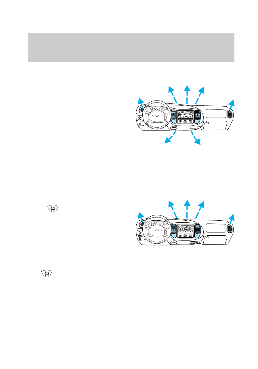
The FLOOR position directs
outside air to flow through the
floor vents.
Select FLR & DEF for air to flow
through these vents:
The FLR & DEF position directs
outside air to flow through the
floor vents and the windshield
defroster vents. The air
conditioning will function to defog
the windows provided the outside
temperature is above 10°C (50°F).
Select
for air to flow through
these vents:
The
position directs outside
air to flow through the windshield
defroster vents. The air
conditioning will function to defog
the windows provided the outside
temperature is above 10°C (50°F).
P
HI
LO
OFF
*
A/C
*
MAX
A/C
REW
1
FF
2
SIDE 1-2
3
FM 1
ST
VOL – PUSH ON
AM
FM
BASSTREB
BAL FADE
AUTO
SET
CLK
SEEK
TUNE
DISCS
SCAN
4
DOLBY SYSTEM
EJ
TAPE CD
COMP
5
SHUFFLE
6
P
HI
LO
OFF
*
A/C
*
MAX
A/C
REW
1
FF
2
SIDE 1-2
3
FM 1
ST
VOL – PUSH ON
AM
FM
BASSTREB
BAL FADE
AUTO
SET
CLK
SEEK
TUNE
DISCS
SCAN
4
DOLBY SYSTEM
EJ
TAPE CD
COMP
5
SHUFFLE
6
f12_air_conditioning
Controls and features
28
Air conditioning
Select A/C for air conditioned air
to flow through these vents:
The A/C mode directs outside air
conditioned air to flow through the
instrument panel vents. The A/C
mode can be used for heating,
ventilating and defogging the
windows or air conditioning. The
A/C mode only functions if the
outside temperature is above 10°C
(50°F).
Select MAX A/C for air to flow
through these vents:
The MAX A/C mode recirculates
the cabin air and directs it to flow
through the instrument panel
vents. The MAX A/C mode can be
used for air conditioning or
heating. This mode is noisier but
more economical than the A/C
mode. The MAX A/C mode only
functions if the outside
temperature is above 10°C (50°F).
P
HI
LO
OFF
*
A/C
*
MAX
A/C
REW
1
FF
2
SIDE 1-2
3
FM 1
ST
VOL – PUSH ON
AM
FM
BASSTREB
BAL FADE
AUTO
SET
CLK
SEEK
TUNE
DISCS
SCAN
4
DOLBY SYSTEM
EJ
TAPE CD
COMP
5
SHUFFLE
6
❄
P
HI
LO
OFF
*
A/C
*
MAX
A/C
REW
1
FF
2
SIDE 1-2
3
FM 1
ST
VOL – PUSH ON
AM
FM
BASSTREB
BAL FADE
AUTO
SET
CLK
SEEK
TUNE
DISCS
SCAN
4
DOLBY SYSTEM
EJ
TAPE CD
COMP
5
SHUFFLE
6
❄
Controls and features
29
OFF position
Select the OFF position for all
climate control functions to cease.
The outside inlet door will close
and the fan is shut off.
Maximum heating
Set mode control to FLOOR, turn
temperature control to maximum
heat (red) and set fan speed
control to HI.
Maximum cooling
Set mode control to MAX A/C, turn
the temperature control to
maximum cool (blue) and set fan
speed control to HI.
Ventilating with outside air
Set mode control to PANEL &
FLOOR or FLOOR, turn the
temperature control to the desired
temperature and turn fan speed
control to the desired speed.
FLR
& DEF
MAX
A/C
FLOOR
PANEL &
FLOOR
DEF
OFF
PANEL
A/C
WARMCOOL
LO
HI
FLR
& DEF
MAX
A/C
FLOOR
PANEL &
FLOOR
DEF
OFF
PANEL
A/C
WARMCOOL
LO
HI
FLR
& DEF
MAX
A/C
FLOOR
PANEL &
FLOOR
DEF
OFF
PANEL
A/C
WARMCOOL
LO
HI
f12_max_heat
f12_max_cool
f12_ventilating
f12_defrosting
Controls and features
30
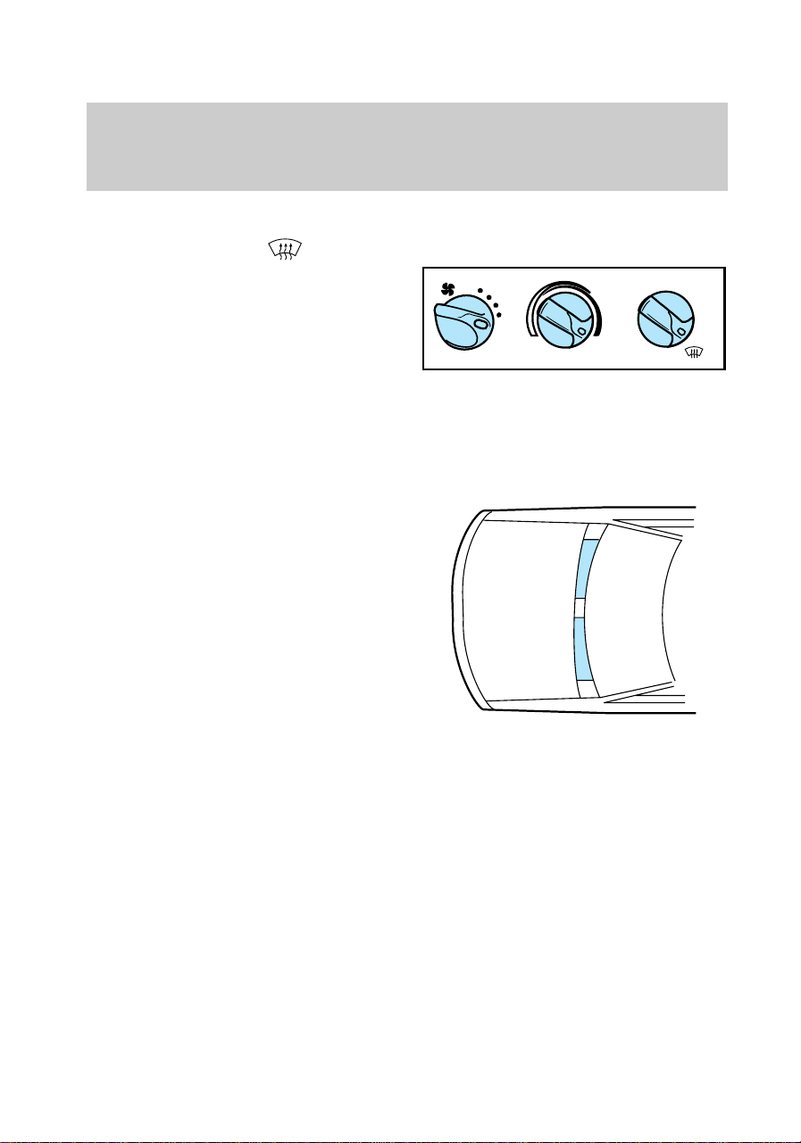
Defrosting windshield
Set mode control to or FLR &
DEF, turn temperature control to
maximum heat (red) and set fan
speed control to HI.
Drive with the climate control
system on (in either the heating or
air conditioning mode) to reduce
humidity in your vehicle.
To prevent air intake restriction,
remove any snow, ice or leaves
from the air intake area located
directly under the windshield.
FLR
& DEF
MAX
A/C
FLOOR
PANEL &
FLOOR
DEF
OFF
PANEL
A/C
WARMCOOL
LO
HI
f12_column_overall
Controls and features
31
Positions of the ignition
1 (Accessory) - allows electrical
accessories such as the audio
system and wiper/washer to
operate when the engine is not
running.
2 (Lock) - locks the steering
wheel and automatic gearshift
lever (if equipped).
3
5
2
4
1
f12_ignition_positions
Controls and features
32

3 (Off) - shuts off the engine and
all accessories without locking the
steering wheel.
4 (On) - tests the warning lights.
Key remains here when engine is
running.
5 (Start) - cranks the engine. Key
returns to 4(On) when released.
Speed control (if equipped)
To turn speed control on
• Press ON
To turn speed control off
• Press OFF or
• Turn off the vehicle ignition.
Once speed control is switched off,
the previously programmed set
speed will be erased.
To set a speed
Press SET ACCEL. For speed
control to operate, the speed
control must be ON and the
vehicle speed must be greater than
48 km/h (30 mph).
ON
OFF
RES
SET
ACCEL
COAST
f12_speed_cont
com_speed_on.01
com_speed_off.01
com_set_speed.01
Controls and features
33
If you drive up or down a steep
hill, your vehicle speed may vary
momentarily slower or faster than
the set speed. This is normal.
Speed control cannot reduce the
vehicle speed if it increases above
the set speed on a downhill. If
your vehicle speed is faster than
the set speed while driving on a
downhill in Overdrive, you may
want to shift to the next lower
gear to reduce your vehicle speed.
If your vehicle slows downs more
than 16 km/h (10 mph) below your
set speed on an uphill, your speed
control will disengage. This is
normal. Pressing RES will
re-engage it.
Do not use the speed
control in heavy traffic or
on roads that are winding,
slippery, or unpaved.
To set a higher speed
• Press and hold SET ACCEL.
Release the switch when the
desired vehicle speed is
reached, or
• Press and release SET ACCEL.
Each press will increase the set
speed by 1.6 km/h (1 mph) or
• Accelerate with your accelerator
pedal, then press SET ACCEL.
You may accelerate with the
accelerator pedal at any time
during speed control usage.
Releasing the accelerator pedal will
return your vehicle speed to the
RES
SET
ACCEL
COAST
com_speed_up.01
Controls and features
34
previously programmed set speed.
To set a lower set speed
• Press and hold COAST. Release
the switch when the desired
vehicle speed is reached, or
• Press and release COAST. Each
press will decrease the set
speed by 1.6 km/h (1 mph) or
• Depress the brake pedal. When
the desired vehicle speed is
reached press SET ACCEL.
To return to a set speed
• Press RES. For RES to operate,
the vehicle speed must be faster
than 48 km/h (30 mph).
To disengage speed control
• Depress the brake pedal.
Disengaging the speed control will
not erase the previously
programmed set speed.
RES
SET
ACCEL
COAST
RES
SET
ACCEL
COAST
com_slow_down.01
com_resume_feature.01
com_disengage_speed_control.01
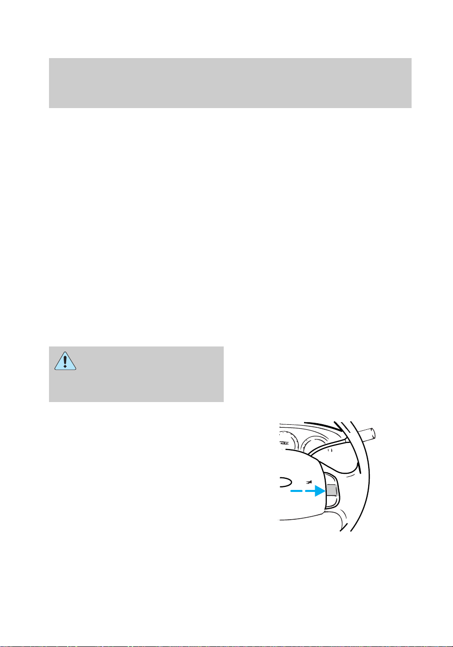
f12_wiper_washer
Controls and features
35
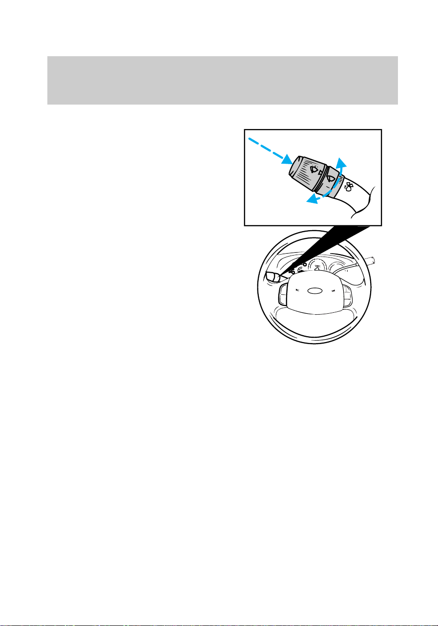
Wiper/washer controls
• Push and hold the end to
activate the washer.
• Push end briefly for a single
wipe.
• Push and hold for a constant
cycle.
• Turn the control to adjust
intermittent wiper speed.
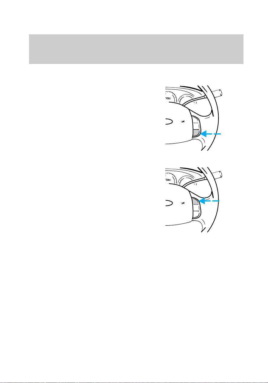
f12_high_beams
Controls and features
36
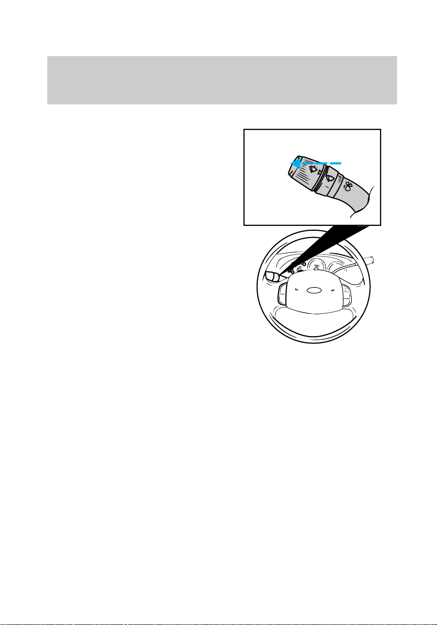
High beam control
• Push the stalk forward to
activate the high beam lamps.
• Pull the stalk towards you to
activate the “flash to pass”
function.
Turn signals
Push the stalk down to activate
the left turn signal; push the stalk
up to activate the right turn signal.
f12_overdrive
Controls and features
37
Overdrive control
Activating overdrive
D
(Overdrive) is the normal
drive position for the best fuel
economy.
The overdrive function allows
automatic upshifts to second, third
and fourth gear.
Deactivating overdrive
Press the transmission control
switch on the end of the gearshift
lever. The transmission control
indicator light (TCIL) (OFF) will
illuminate on the end of the
gearshift lever.
Transmission will operate in gears
one through three. To return to
normal overdrive mode, press the
transmission control switch again.
The TCIL (OFF) will no longer be
illuminated.
When you shut off and re-start
your vehicle, the transmission will
automatically return to normal
D
(Overdrive) mode.
OVERDRIVE OFF
f12_activate_od
f12_deactivate_od
Controls and features
38
Deactivate overdrive whenever
driving conditions (i.e., city traffic,
hilly terrain, etc.) cause the
transmission to shift excessively
between
D
(Overdrive) and
D(Drive) ranges. Also deactivate
D
(Overdrive) when:
• driving with a heavy load
• towing a trailer up or down
steep hills
• additional engine braking is
desired.
Transmission control indicator
light (TCIL)
The TCIL (OFF), located on the
end of the gearshift lever, may
flash steadily if a malfunction has
been detected. If the TCIL is
flashing, contact your Ford dealer
as soon as possible. If this
condition persists, damage to the
transmission could occur.
Hazard flasher control
Use only in an emergency to warn
traffic of vehicle breakdown,
approaching danger, etc. Depress
control to activate all indicators
simultaneously. Depress control
again to turn off. The hazard lights
can be operated when the ignition
is off.
OVERDRIVE OFF
f12_tcil_light
f12_hazard
f12_tilt_steer
Controls and features
39
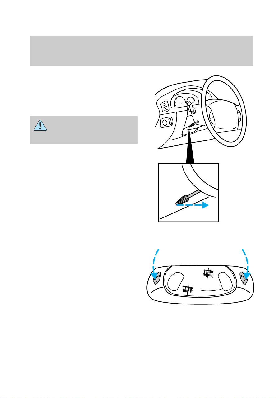
Tilt steering (if equipped)
Pull the lever to adjust the
steering column angle. Push the
lever back up to lock the steering
wheel into position.
Never adjust the steering
wheel when the vehicle is
moving.
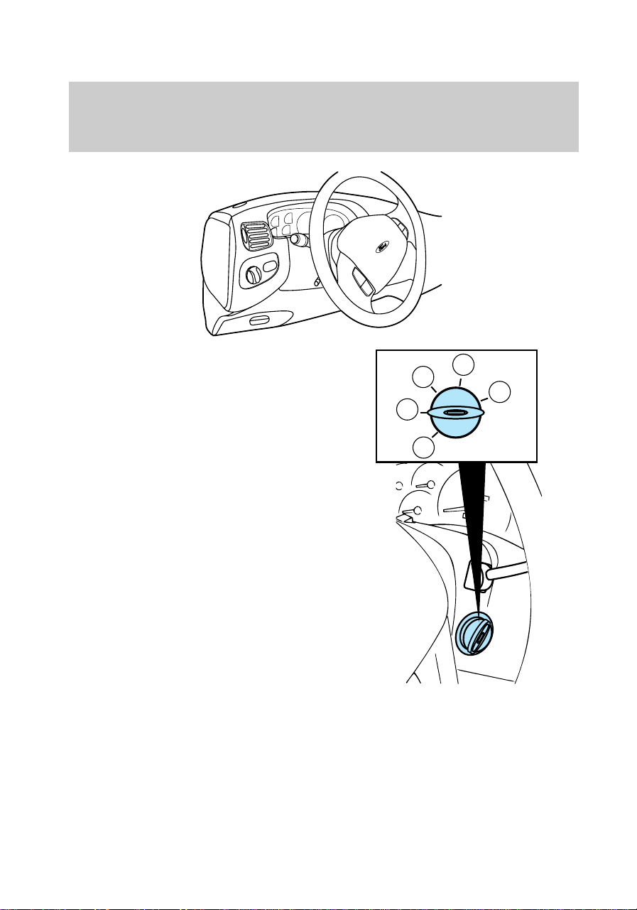
OVERHEAD CONTROLS
Dome/map lamp (if equipped)
Press either the left or right switch
to activate the left or right map
lamps.
f12_overhead_overall
f12_domemap_lamp
f12_illuminated_entry
Controls and features
40
Illuminated entry
The interior lamps illuminate
when:
• either front door handle is lifted
or
• the remote entry system is used
to unlock the door or sound the
personal alarm. See Remote
entry system for more
information.
The system automatically turns off
after 25 seconds or when the
ignition is turned to the Start or
Accessory positions.
The inside lights will not turn off
if:
• they have been turned on with
the dimmer control or
• any door is open.
Battery saver
Battery saver is a feature that
automatically shuts off power to
these lights after 40 minutes:
• glove box lamp
• engine compartment lamp
• overhead lamps.
Battery saver prevents the battery
from being drained if these lights
are left on or if a door is not
completely closed. Battery power
is restored if the remote entry
transmitter is used, any door is
opened or the ignition key is
turned to On.
LOCK
UN
LOCK
PANIC
f12_battery_saver
Controls and features
41
Power windows (if equipped)
Driver-side window control
• Press rear of switch to open
window.
• Press front of switch to close
window.
The driver-side power window has
a one-touch down feature. When
AUTO is fully pressed (two clicks
will be heard), the driver-side
window will move completely
down. This feature can be
cancelled by pressing the
driver-side power window switch
again.
LU
AUTO
LR
f12_driver_control
f12_pass_control
Controls and features
42
Passenger-side window
controls
• Press rear of switches to open
passenger window.
• Press front of switches to close
passenger window.
Accessory delay (if equipped)
With accessory delay, the window
switches may be used for up to ten
minutes after the ignition switch is
turned to the Off position or until
either door is opened.
LU
AUTO
LR
L
U
f12_acc_delay
f12_power_locks
Controls and features
43
Power locks (if equipped)
Driver and passenger controls
• Press L to lock both doors.
• Press U to unlock both doors.
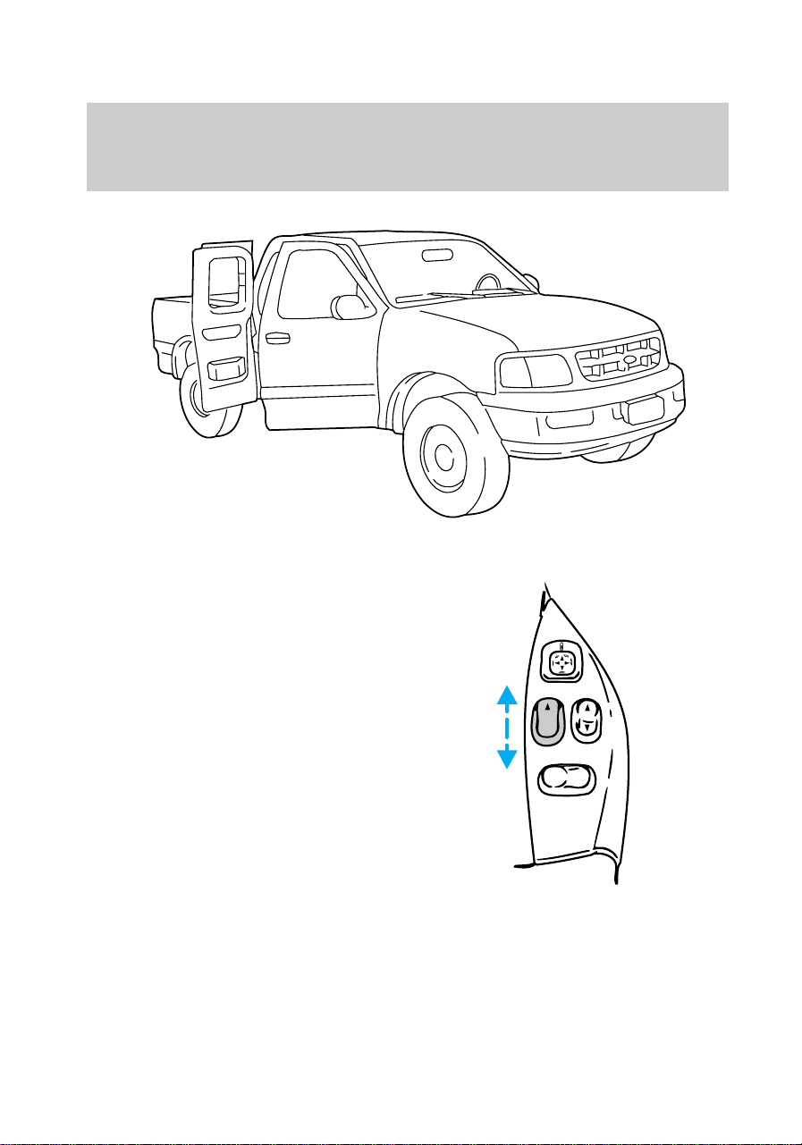
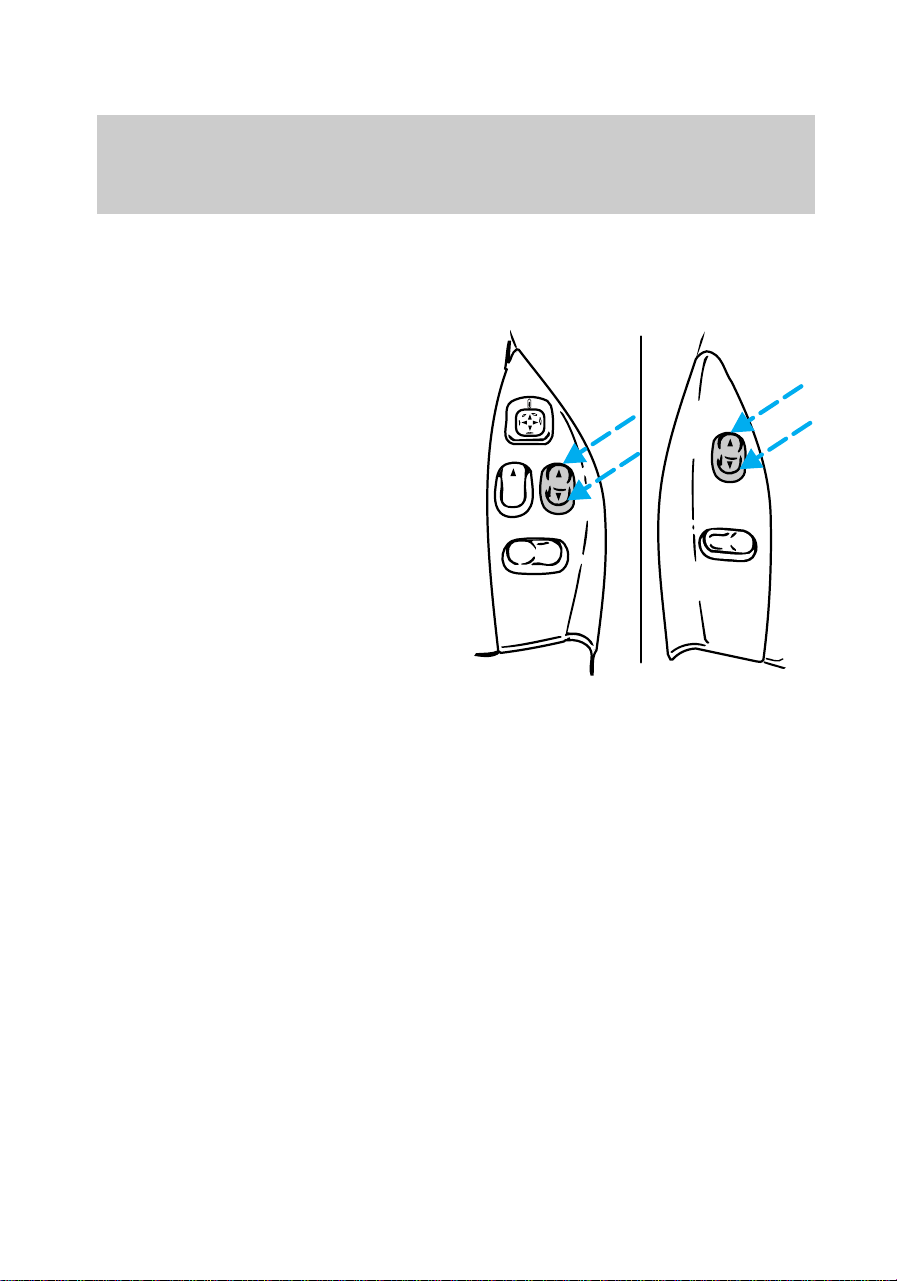
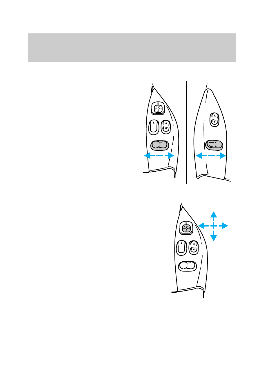
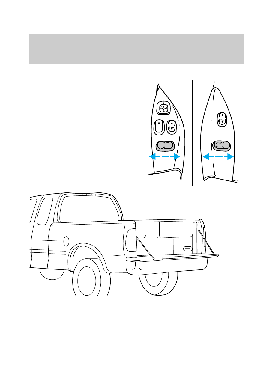
Dual electric remote control
mirrors (if equipped)
1. Select driver or passenger
mirror by moving selector lever left
(L) for driver or right (R) for
passenger.
2. Move the mirror control until
mirror reaches desired position.
3. Move selector lever to center to
“lock” position.
LU
AUTO
LR
L
U
LU
AUTO
LR
f12_driver_control
f12_remote_mirrors
Controls and features
44
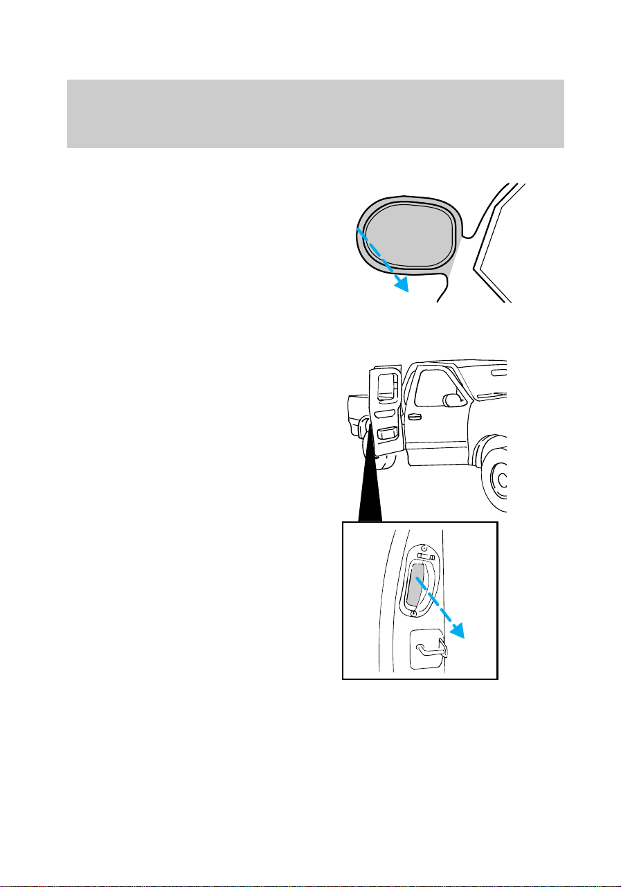
Fold-away mirrors
Pull the side mirrors in carefully
when driving through a narrow
space, like an automatic car wash.
Third door (if equipped)
On SuperCab models a third door
is located behind the passenger
door. This door allows for
improved access to the rear
passenger compartment.
To open the third door (the
passenger door must be open) pull
either the handle located in the
f12_third_door
Controls and features
45
door jamb or the handle on the
interior of the third door.
• To lock the third door, lock the
passenger door or press the
power lock switch (if equipped).
• When the passenger door is
unlocked, the third door cannot
be opened until the passenger
door is opened. The third door
can then be opened.
LU
AUTO
LR
L
U
f12_trunk_overall
Controls and features
46
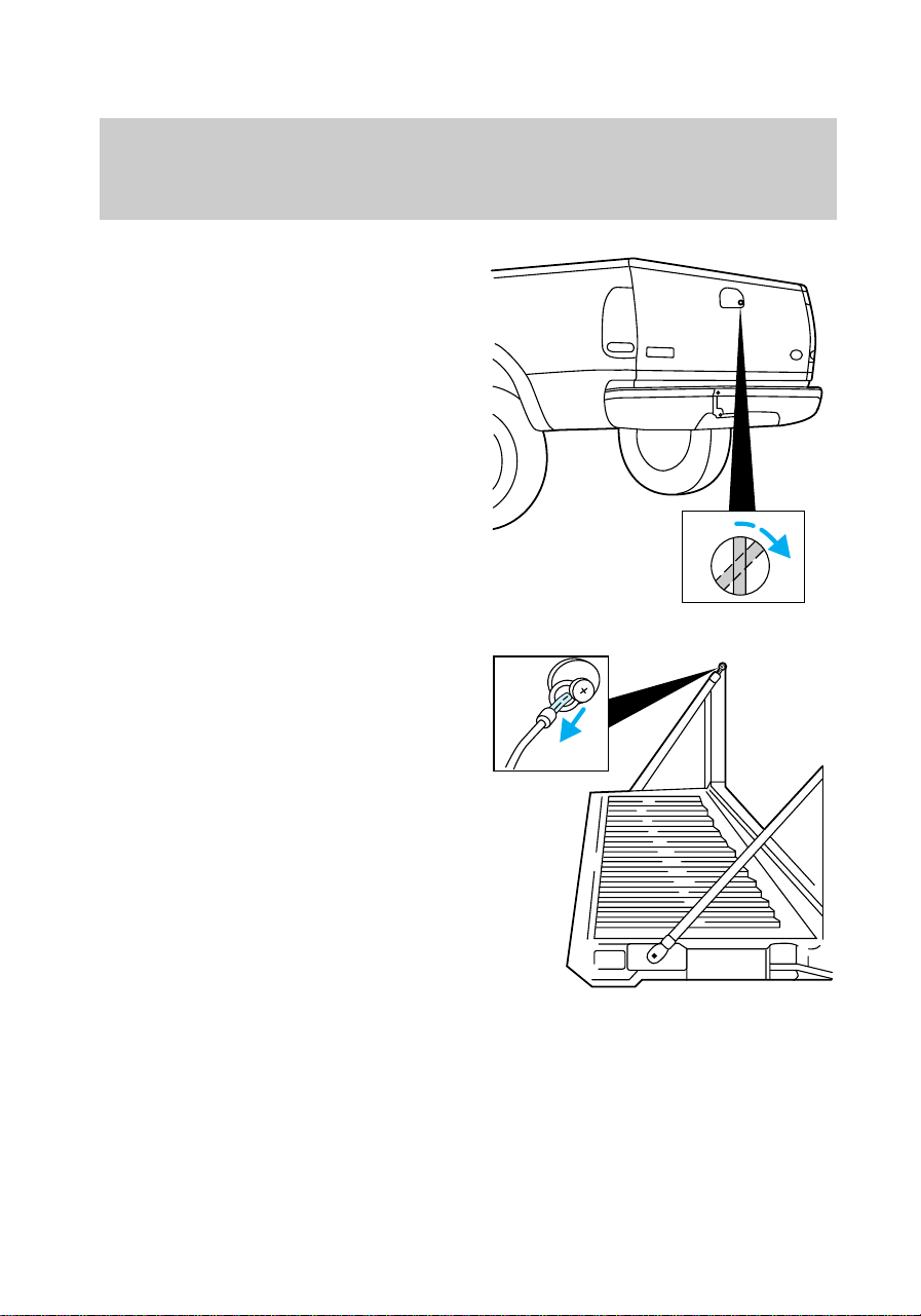
Tailgate lock (if equipped)
Your vehicle is equipped with a
tailgate lock designed to prevent
theft of the tailgate.
• Insert ignition key and turn to
the right to engage lock.
• Turn ignition key to the left to
unlock.
Tailgate removal
Your tailgate is removable to allow
more room for loading.
1. Lower the tailgate.
2. Use a screwdriver to pry the
spring clip (on each connector)
past the head of the support
screw. Disconnect cable.
3. Disconnect the other cable.
4. Lift tailgate to a 45 degree
angle.
5. Lift right side off of its hinge.
6. Lift left side off of its hinge.
f12_tailgate_lock
f12_tailgate_removal
f12_antitheft
Controls and features
47
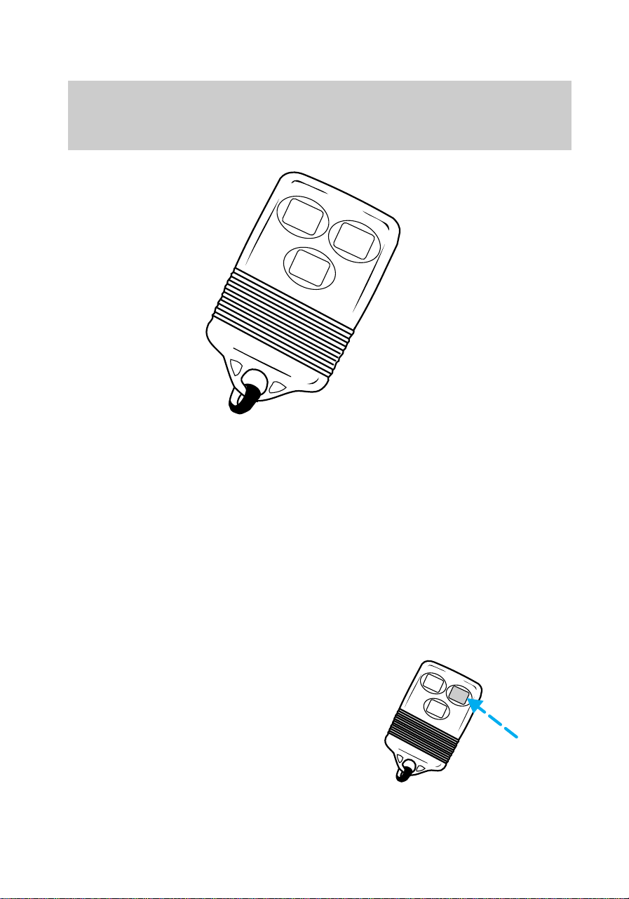
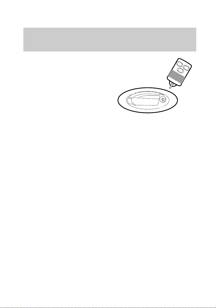
Remote entry system (if
equipped)
The remote entry system allows
you to lock or unlock all vehicle
doors without a key. The remote
entry features only operate with
the ignition key in the Off position.
It also arms and disarms the
anti-theft system (for more
information on the anti-theft
system, refer to Anti-theft system
in this chapter.)
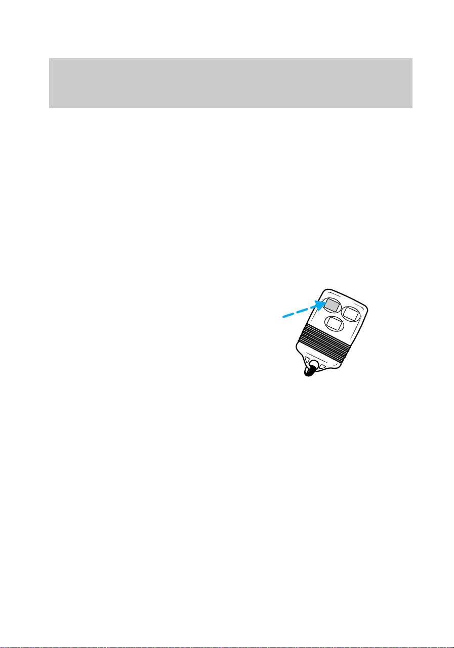
Unlocking the doors
Press UNLOCK to unlock the
driver door. The interior lamps will
illuminate.
Press UNLOCK a second time
within five seconds to unlock all
doors.
LOCK
PANIC
UN
LOCK
LOCK
PANIC
UN
LOCK
f12_remote_entry
f12_unlocking_doors
f12_locking_doors
Controls and features
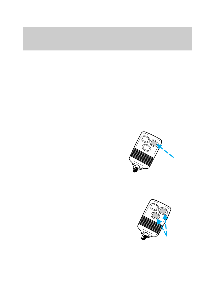
48
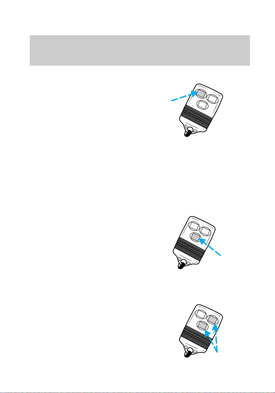
Locking the doors
Press LOCK to lock all doors. To
confirm that all doors are closed
and locked, press the LOCK
control a second time. The doors
will lock again, the horn will chirp
and the lamps will flash.
This process will also arm your
anti-theft system. If the horn
chirps twice, a door is still ajar and
the anti-theft system will not arm.
For more information on arming
the anti-theft system, refer to
Anti-theft system in this chapter.
Sounding a panic alarm
Press PANIC to activate the alarm.
To deactivate the alarm, press the
PANIC control again or turn the
ignition to the Accessory or On
position.
Arming and disarming the alarm
system
Your remote entry system will:
• automatically arm the factory
installed anti-theft system when
the doors are closed and locked.
• reset the triggered anti-theft
alarm (when either the
UNLOCK or PANIC controls are
pressed).
PANIC
UN
LOCK
LOCK
LOCK
PANIC
UN
LOCK
PANIC
UN
LOCK
LOCK
f12_sounding_panic
f12_arm_disarm_system
Controls and features
49

The remote entry system may not
arm and disarm non-factory
installed anti-theft systems.
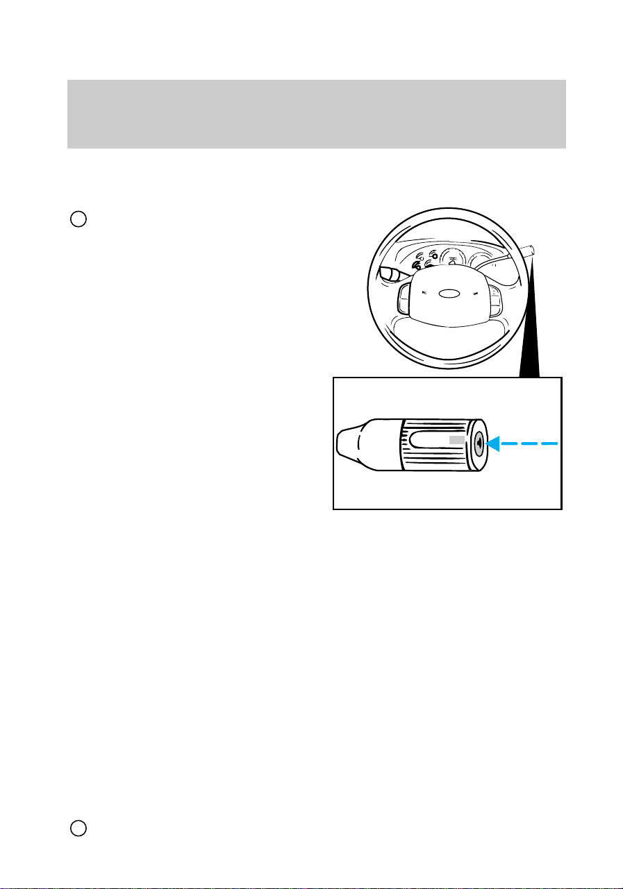
Replacing the batteries
The transmitter is powered by two
coin type three-volt lithium
batteries. A decrease in operating
range can be caused by:
• battery failure
• weather conditions
• structures around the vehicle.
Replacement batteries for the
remote entry transmitters may be
purchased at pharmacies, watch
stores or at authorized dealers.
To replace the batteries:
1. Twist a thin coin between the
two halves of the transmitter. DO
NOT TAKE THE FRONT PART OF
THE TRANSMITTER APART.
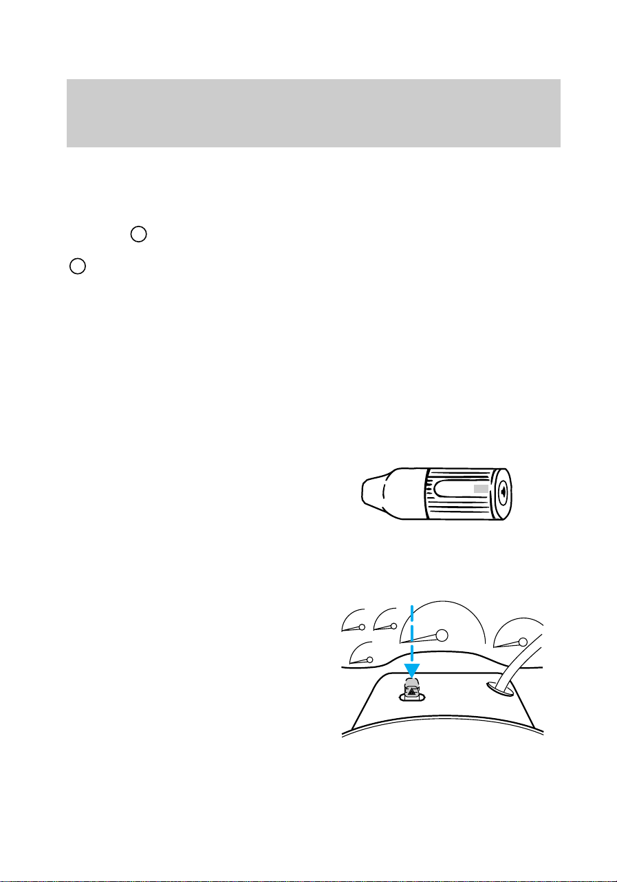
2. Place the positive (+) side of
the new batteries down.
3. Snap the two halves back
together.
Replacing lost transmitters
Take all your vehicle’s transmitters
to your dealer for reprogramming
if:
• a transmitter is lost or
• you want to purchase additional
transmitters (up to four total)
Additional information about
remote entry
This device complies with Part 15
of the FCC rules. Operation is
f12_replacing_batteries
f12_fcc_rule
Controls and features
50
subject to the following two
conditions: (1) This device may
not cause harmful interference,
and (2) This device must accept
any interference received,
including interference that may
cause undesired operation.
Anti-theft system (if equipped)
When armed, the anti-theft system
prevents unauthorized entry into
your vehicle.
Arming the anti-theft system
Turn the ignition to Off and use
one of the following methods to
arm the system:
• Press the LOCK control on the
remote entry transmitter or
• Open either door and press the
power door lock switch.
Identifying an armed system
While the system is arming, the
THEFT light in the instrument
cluster will illuminate for 30
seconds. After 30 seconds, THEFT
will flash, indicating the system is
armed.
If the system is armed with the
doors open, the THEFT light will
stay illuminated until all the doors
are closed and then illuminate for
30 seconds and begin flashing.
When an unauthorized entry
occurs, the activated system will:
• flash the headlamps, parking
lamps and the THEFT light
PANIC
UN
LOCK
LOCK
f12_arming_anti_theft
f12_identifying_armed
Controls and features
51
• sound the horn
• prohibit the vehicle from
starting.
The flashing headlamps and the
honking horn automatically shut
off after about three minutes and
will remain off unless another
unauthorized entry is attempted.
However, the vehicle will not start
until the system is disarmed.
Disarming an untriggered
anti-theft system
Press the UNLOCK control or
unlock either door with the key to
disarm the untriggered system. If
the driver armed the system but
did not exit the vehicle, disarm the
system by inserting the key and
turning the ignition to On.
Disarming a triggered anti-theft
system
Press either the UNLOCK or
PANIC control or unlock either
door with the key to disarm the
system.
A triggered system may also be
disarmed by inserting the key and
turning the ignition to Accessory
or On.
LOCK
PANIC
UN
LOCK
PANIC
UN
LOCK
LOCK
f12_disarming_untriggered
Controls and features
52
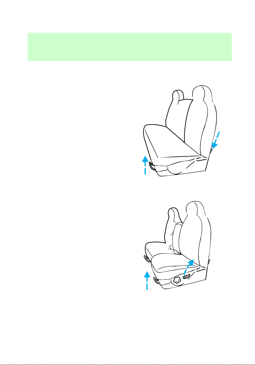
SEATING
Full bench seat (if equipped)
• Lift the release bar to move the
seat forward or backward.
Ensure that the seat is relatched
into place.
• Push down the release lever to
quickly fold the seatback
forward.
60/40 split bench seat (if
equipped)
• Lift the release bar to move the
seat forward or backward.
Ensure the seat is relatched into
place.
f12_adjusting_bench
f12_split_bench
Seating and safety restraints
53
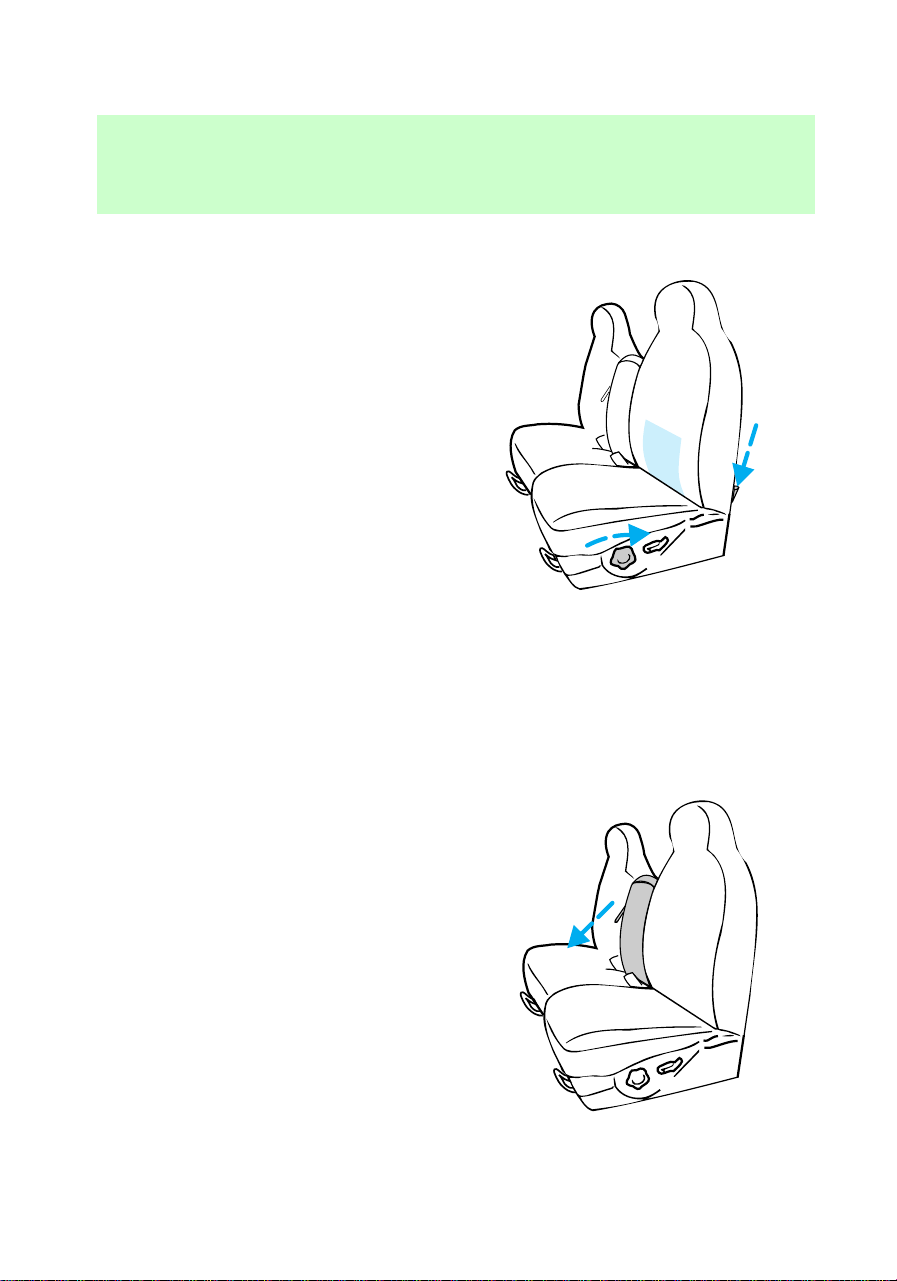
• Pull the seatback handle up to
recline the seat.
• Turn the lumbar support dial to
adjust firmness.
• Push down the release lever to
quickly fold the seatback
forward.
Center armrest (if equipped)
Pull the strap down to move the
armrest down.
f12_adjust_man_bucket
Seating and safety restraints
54
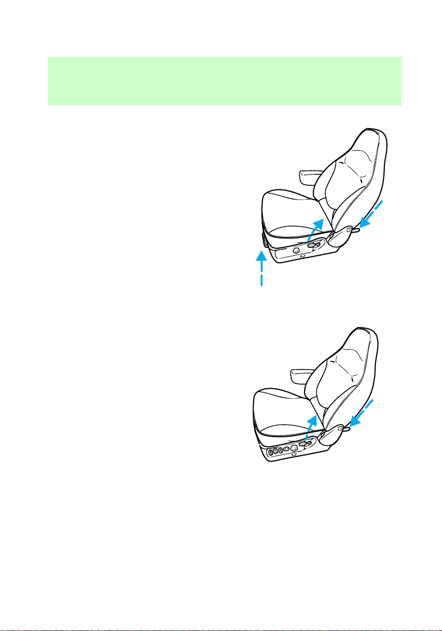
Captain’s chair (if equipped)
• Lift the release bar to move the
seat forward or rearward.
Ensure that the seat is relatched
into place.
• Pull the seatback handle up to
recline the seat.
• Push the release lever down to
quickly fold the seatback
forward.
Power seats (if equipped)
• Pull up the seatback handle to
recline the seat.
• Push down the release lever to
quickly fold the seatback
forward.
f12_adjust_power_seat
Seating and safety restraints
55
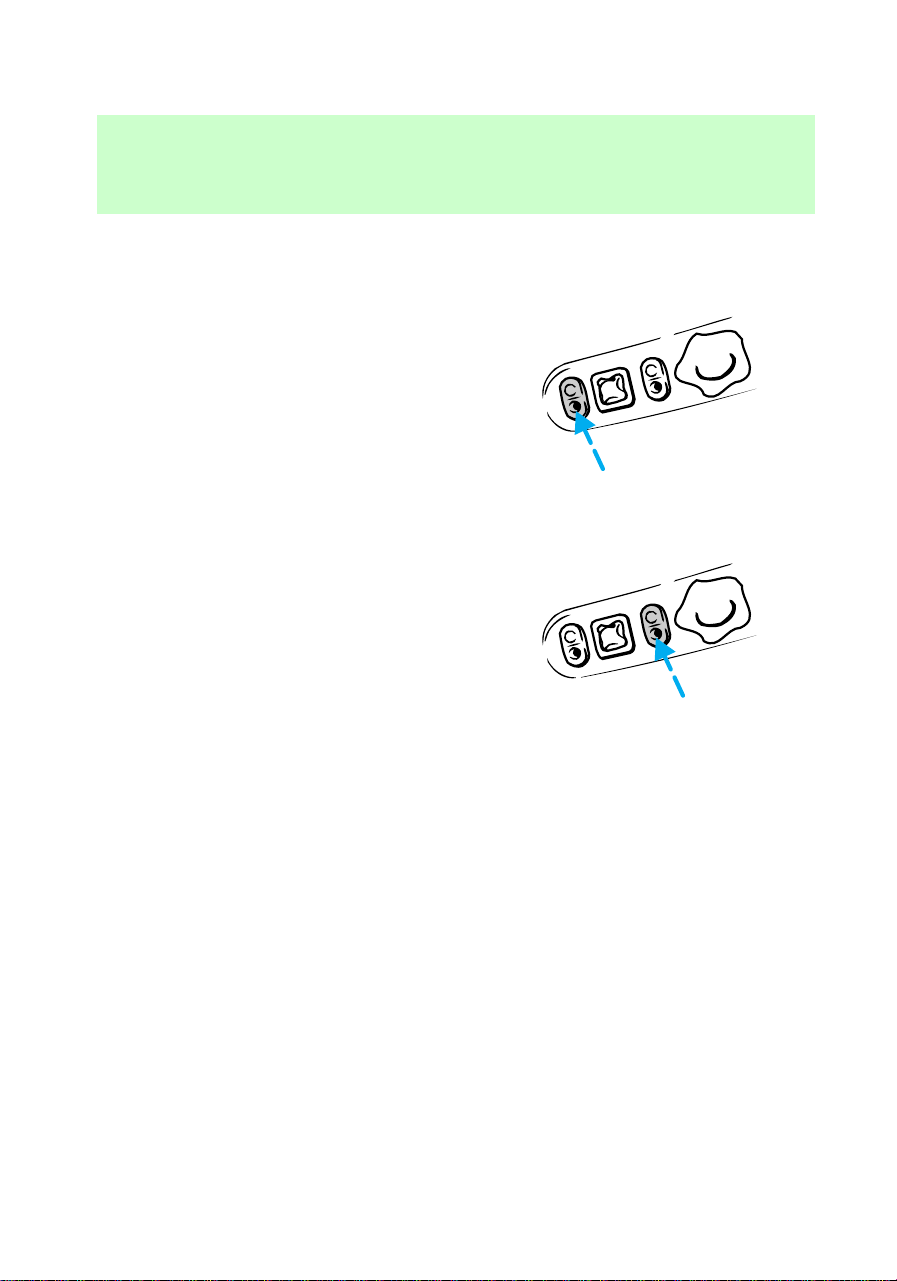
Press switch to tilt the front of the
seat up or down.
Press switch to tilt the rear of the
seat up or down.
Seating and safety restraints
56
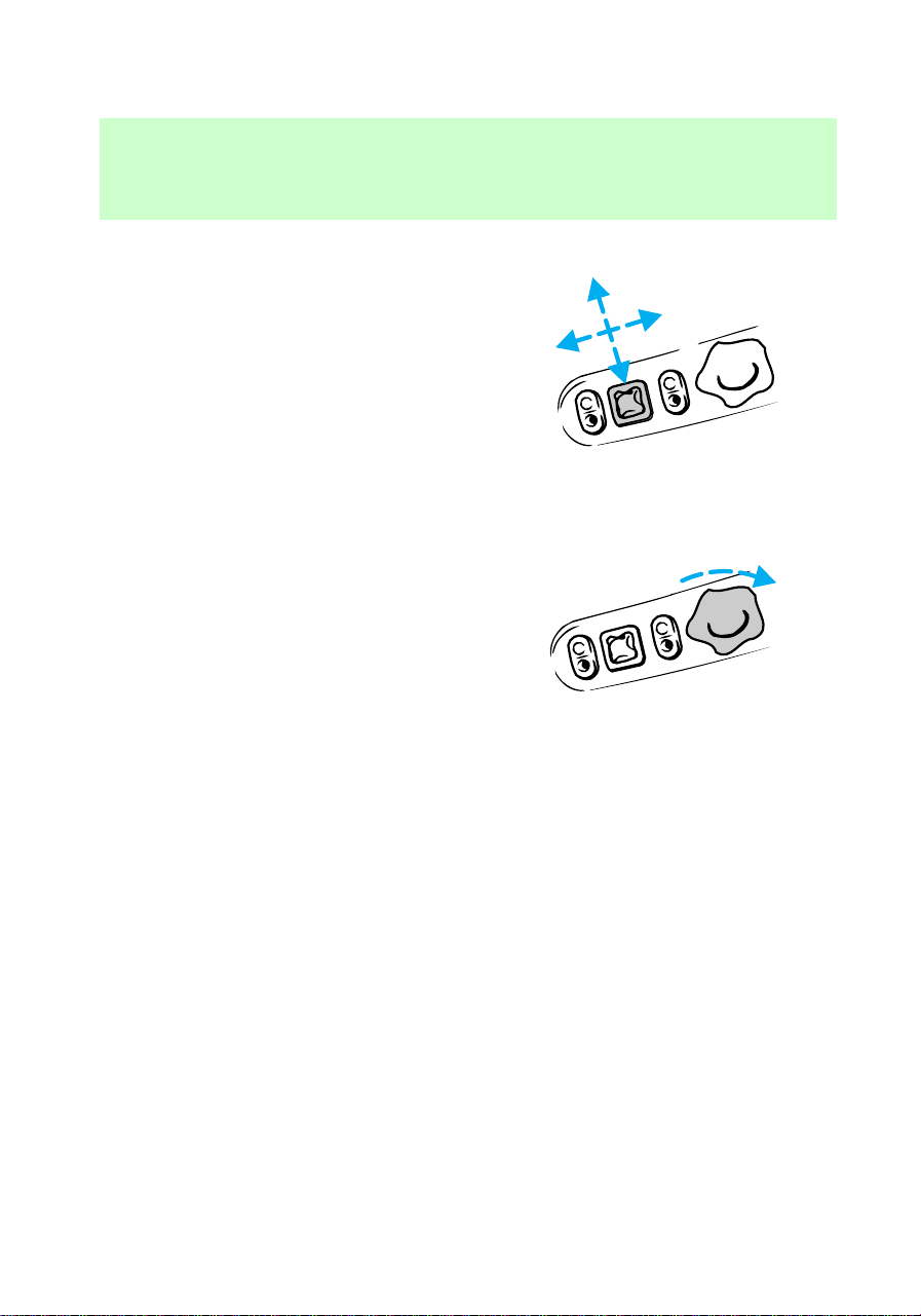
Press control to move the seat
forward, backward, up or down.
Adjustable lumbar support
Turn the lumbar support dial
clockwise to adjust firmness.
f12_adjust_lumbar
f12_rear_bench
Seating and safety restraints
57
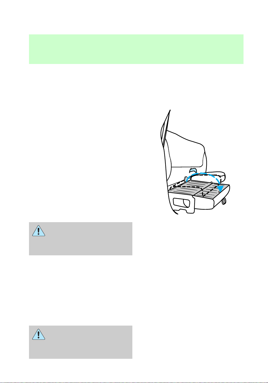
60/40 split rear seat (if
equipped)
When folded down, the rear seats
provide a “load floor” of additional
storage space. To fold down the
rear seats:
1. Pull the straps to lower the seat
cushions.
2. Store the center safety belt in
the opening on the seat back.
When returning the seats to their
normal position:
1. Clear the load floor before
folding seat up.
2. Ensure the seat cushion is
latched into place.
3. Remove center safety belt from
its stowed position.
Check to assure that 60/40
Split rear seat cushion is
latched by pulling up and
forward on lap belt buckles.
SAFETY RESTRAINTS
Safety restraints precautions
The use of safety belts helps to
restrain you and your passengers
in case of a collision. In most
states and Canada, the law
requires the use of safety belts.
Always drive and ride with
your seatback upright and
the lap belt snug and low across
the hips.
f12_seat_belts
f12_safety_res_prec
Seating and safety restraints
58

All occupants of the
vehicle, including the
driver, should always wear their
safety belts.
To prevent the risk of
injury, make sure children
sit where they can be properly
restrained.
It is extremely dangerous
to ride in a cargo area,
inside or outside of a vehicle. In
a collision, people riding in these
areas are more likely to be
seriously injured or killed. Do not
allow people to ride in any area
of your vehicle that is not
equipped with seats and safety
belts. Be sure everyone in your
vehicle is in a seat and using a
safety belt properly.
f12_using_sr_properly
Seating and safety restraints
59
Using safety restraints properly
Combination lap and shoulder
belts
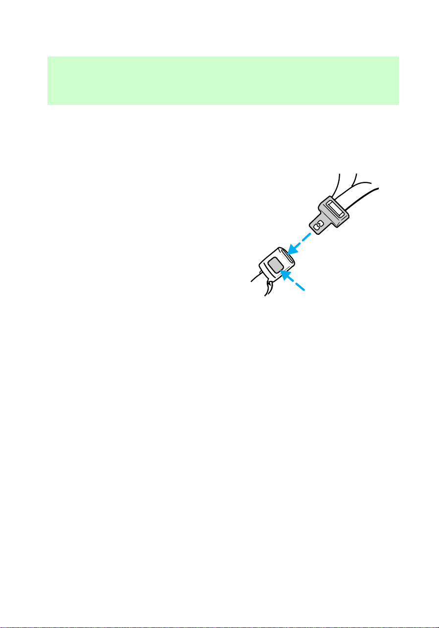
1. To connect the safety belt,
insert the tongue into the buckle.
2. To disconnect the safety belt,
push the red release button and
remove the tongue from the
buckle.
The front and rear (if equipped)
outboard safety restraints in your
vehicle are combination lap and
shoulder safety belts. The outboard
passenger safety belts have the
two types of locking modes
described below:
Vehicle sensitive (emergency)
locking mode
The vehicle sensitive mode is the
normal retractor mode, allowing
free shoulder belt length
adjustment to your movements and
locking in response to vehicle
movement. For example, if the
driver brakes suddenly or turns a
corner sharply, or the vehicle
receives an impact of
approximately 8 km/h (5 mph) or
more the combination safety belts
will lock to help reduce forward
PRESS
f12_comb_lap_sh_belts
Seating and safety restraints
60
movement of the driver and
passengers.
The front seat belt system can also
be made to lock manually by
quickly pulling on the shoulder
belt. Rear seat belts (if equipped)
cannot be made to lock up by
pulling quickly on the belt.
Automatic locking mode
In this mode, the shoulder belt is
automatically pre-locked. The belt
will still retract to remove any
slack in the shoulder belt.
The automatic locking mode is not
available on the driver safety belt.
When to use the automatic
locking mode
• When a tight lap/shoulder belt
fit is desired.
• Any time a child safety seat is
installed in the vehicle. Refer to
Children and infant or child
safety seats later in this chapter.
f12_auto_lock_mode
f12_when_to_use_alr
f12_how_use_alr
Seating and safety restraints
61
Using the automatic locking
mode
The automatic locking mode must
be used when installing a child
safety seat in any outboard
passenger seat.
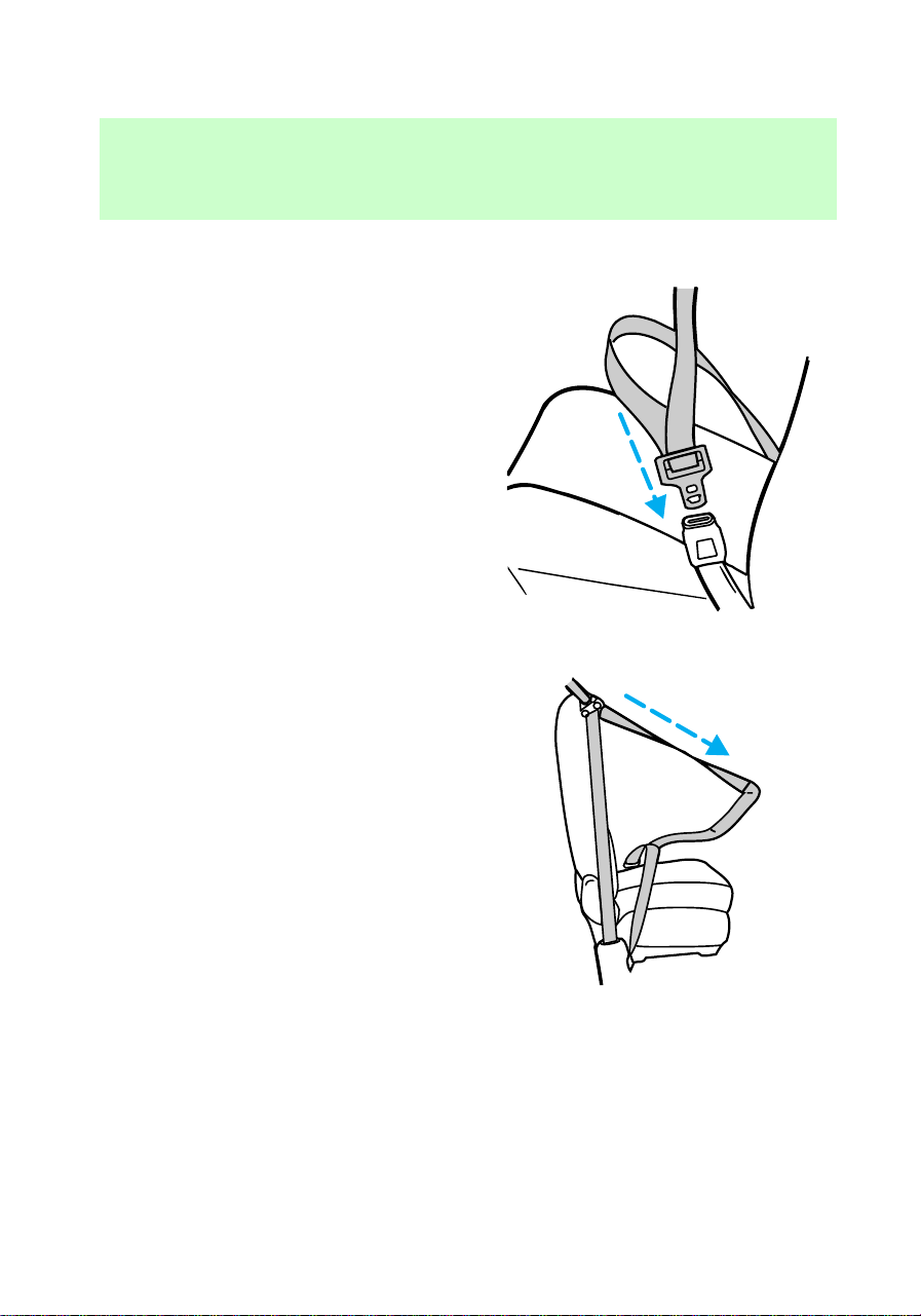
1. Buckle the combination lap and
shoulder belt.
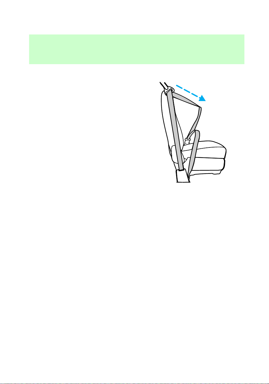
2. Grasp the shoulder belt portion
and pull downward until the entire
belt is extracted.
3. Allow the belt to retract. As the
belt retracts, you will hear a
clicking sound. This indicates that
the safety belt is now in the
automatic locking mode.
Cancelling the automatic
locking mode
Disconnect the combination
lap/shoulder belt and allow it to
completely retract to cancel the
automatic locking mode and
activate the vehicle sensitive
(emergency) locking mode.
f12_cancel_alr
f12_front_sbelt_height_adjust
Seating and safety restraints
62
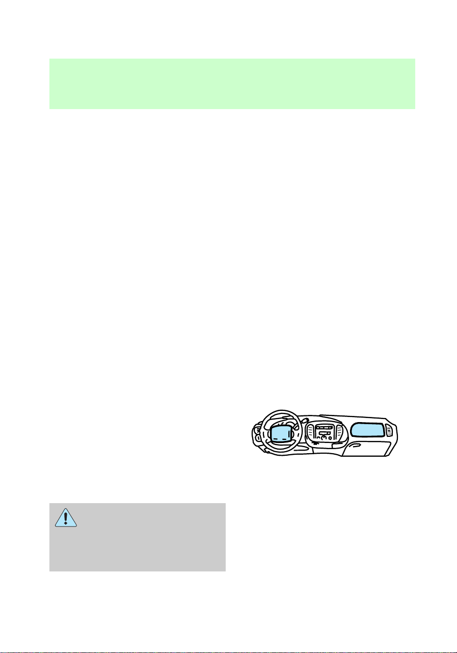
Front seat safety belt height
adjustment
Your vehicle has safety belt height
adjustments for the driver and
passenger seating positions.
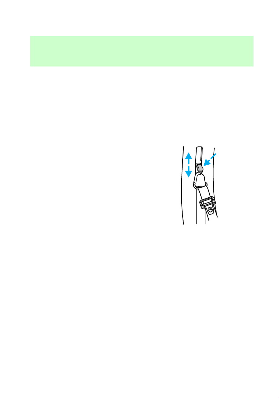
Adjust the height of the shoulder
belt so the belt rests across the
middle of your shoulder.
1. Push the button and slide down
to lower the shoulder belt height.
2. Push the button and slide up to
raise the shoulder belt height.
3. Pull down on the height
adjustment assembly to make sure
it is locked in place.
If you have a SuperCab vehicle,
the front passenger seat
combination lap and shoulder belt
height cannot be adjusted.
Lap belts
Lap belts are located in the center
of the front bench or split bench
seat (if equipped) and rear bench
seat (SuperCab only).
Adjusting lap belts
The lap belt does not have a
retractor to automatically adjust
itself during vehicle movement.
f12_lap_belts
f12_adjusting_lap_belts
Seating and safety restraints
63
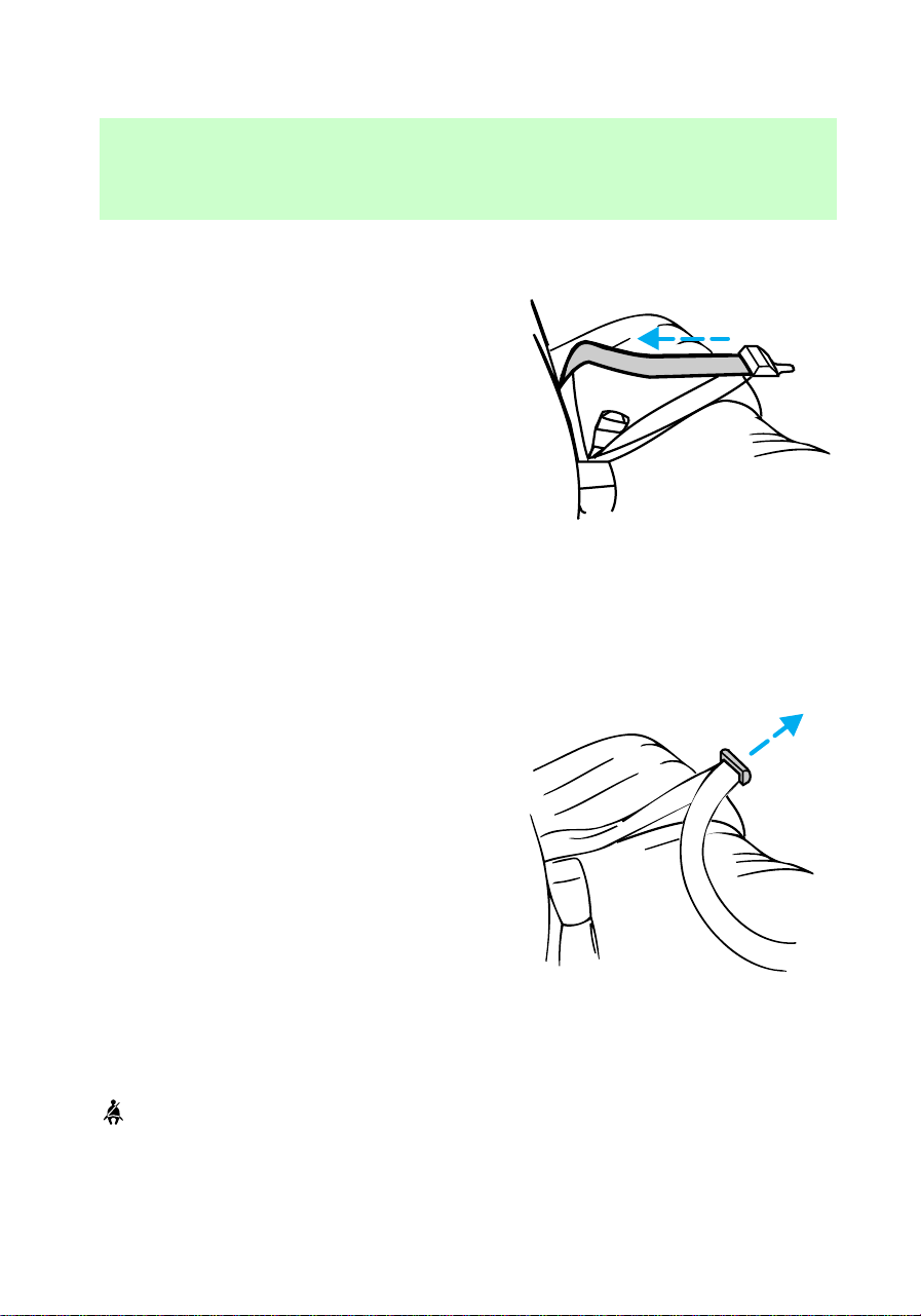
The lap belt must be adjusted
before use.
To shorten the belt:
• Buckle the belt.
• Pull the loose end of the belt
until snug.
To lengthen the belt:
• Tip and pull the tongue. Do not
wear the lap belt around your
waist.
Shorten and fasten the belt when
not in use.
Safety belt warning light and
indicator chime
illuminates in the instrument
cluster and a chime sounds to
remind the occupants to fasten
their safety belts.
f12_sbelt_warning_chime
f12_cond_operation
Seating and safety restraints
64

Conditions of operation
If... Then...
The driver safety belt is not
buckled when the ignition key is
turned to On...
The safety belt indicator
illuminates for 1-2 minutes and
the reminder chime sounds for 4-8
seconds.
The driver safety belt is buckled
while the indicator light is
illuminated and the reminder
chime is sounding...
The safety belt indicator light and
the reminder chime turn off.
The driver safety belt is buckled
before the ignition key is turned to
On...
The safety belt indicator light and
the safety belt reminder chime
remain off.
Safety belt maintenance
Check the safety belt systems
periodically to make sure that they
work properly and are not
damaged. Check the safety belts to
make sure that there are no nicks,
wear or cuts. If your vehicle has
been involved in an accident, have
all the safety belts and child seat
anchoring brackets (if equipped)
examined by a qualified technician.
Failure to replace the
safety belt assembly under
the above conditions could result
in severe personal injuries in the
event of a collision.
Safety belt extension assembly
For some people, the safety belt
may be too short even when it is
fully extended. You can add about
20 cm (8 in.) to the belt length
f12_sbelt_maint
f12_sbelt_extension
Seating and safety restraints
65
with a safety belt extension
assembly (part # 611C22). Safety
belt extensions are available at no
cost from your Ford or
Lincoln/Mercury dealer.
Use only extensions manufactured
by the same supplier as the safety
belt. Manufacturer identification is
located at the end of the webbing
on the label. Also, use the safety
belt extension only if the safety
belt is too short for you when fully
extended. Do not use extension to
change the fit of the shoulder belt
across the torso.
SUPPLEMENTAL RESTRAINT
SYSTEM (SRS)
Important supplemental
restraint system (SRS)
precautions
The supplemental restraint system
is designed to:
• work with the safety belt to
protect the driver and right
front passenger
• reduce certain upper body
injuries
Failure to follow these
instructions will affect the
performance of the safety belts
and increase the risk of personal
injury.
f12_air_bags
com_important_precautions.01
Seating and safety restraints
66

The right front passenger
air bag is not designed to
restrain occupants in the front
seating position.
Do not place objects or
mount equipment on or
near the air bag covers that may
come into contact with an
inflating air bag.
Do not attempt to service,
repair, or modify the Air
Bag Supplemental Restraint
System or its fuses. See your
Ford or Lincoln-Mercury dealer.
Children and air bags
For additional important safety
information, read all information
on safety restraints in this guide.
com_children.01
Seating and safety restraints
67
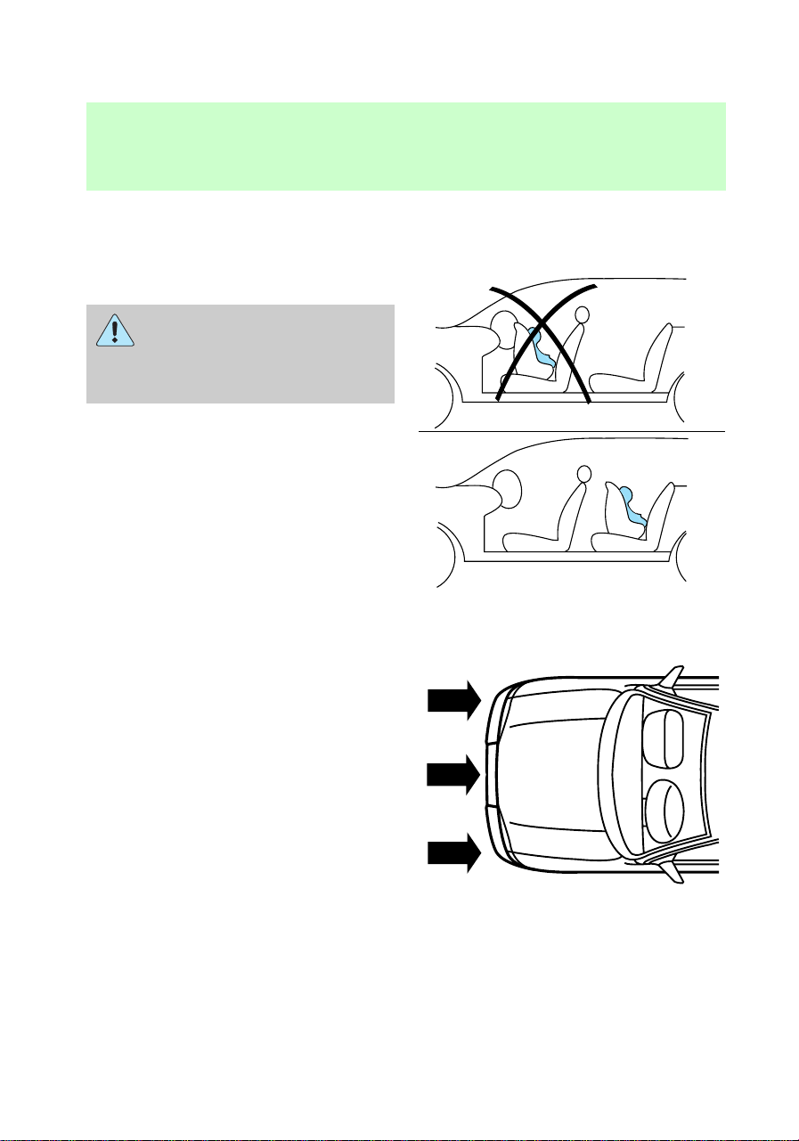
Children should always wear their
safety belts. Failure to follow these
instructions may increase the risk
of injury in a collision.
Rear-facing child seats or
infant carriers should
never be placed in the front
seats.
How does the air bag
supplemental restraint system
work?
The SRS is designed to activate
when the vehicle sustains
sufficient longitudinal deceleration,
similar to hitting a fixed barrier
head on at 12–24 km/h (8–14
mph).
The fact that the air bags did not
inflate in a collision does not mean
that something is wrong with the
system. Rather, it means the forces
com_how_work.01
Seating and safety restraints
68
were not of the type sufficient to
cause activation.
The air bags inflate and deflate
rapidly upon activation.
After air bag deployment, it is
normal to notice a smoke-like,
powdery residue or smell the burnt
propellant. This may consist of
cornstarch, talcum powder (to
lubricate the bag) or sodium
compounds (e.g., baking soda) that
result from the combustion process
that inflates the air bag. Small
amounts of sodium hydroxide may
be present which may irritate the
skin and eyes, but none of the
residue is toxic.
Several air bag system
components get hot after
inflation. Do not touch them
after inflation.
Seating and safety restraints
69

If the air bag is inflated,
the air bag will not
function again and must be
replaced immediately.Ifthe
air bag is not replaced, the
unrepaired area will increase the
risk of injury in a collision.
The SRS consists of:
• driver and passenger air bag
modules (which include the
inflators and air bags),
• one or more impact and safing
sensors,
• a readiness light and tone
• and the electrical wiring which
connects the components.
The diagnostic module monitors its
own internal circuits and the
supplemental air bag electrical
system readiness (including the
impact sensors), the system wiring,
the air bag system readiness light,
the air bag back up power and the
air bag ignitors.
Determining if the system is
operational
The SRS uses a readiness light in
the instrument cluster or a tone to
indicate the condition of the
system. Refer to the Air bag
readiness section in the
Instrumentation chapter. Routine
maintenance of the air bag is not
required.
com_determing_operational.01
Seating and safety restraints
70
A difficulty with the system is
indicated by one or more of the
following:
• The readiness light will either
flash or stay lit.
• The readiness light will not
illuminate immediately after
ignition is turned on.
• A group of five beeps will be
heard. The tone pattern will
repeat periodically until the
problem and light are repaired.
If any of these things happen, even
intermittently, have the SRS
serviced at your dealership or by a
qualified technician immediately.
Unless serviced, the system may
not function properly in the event
of a collision.
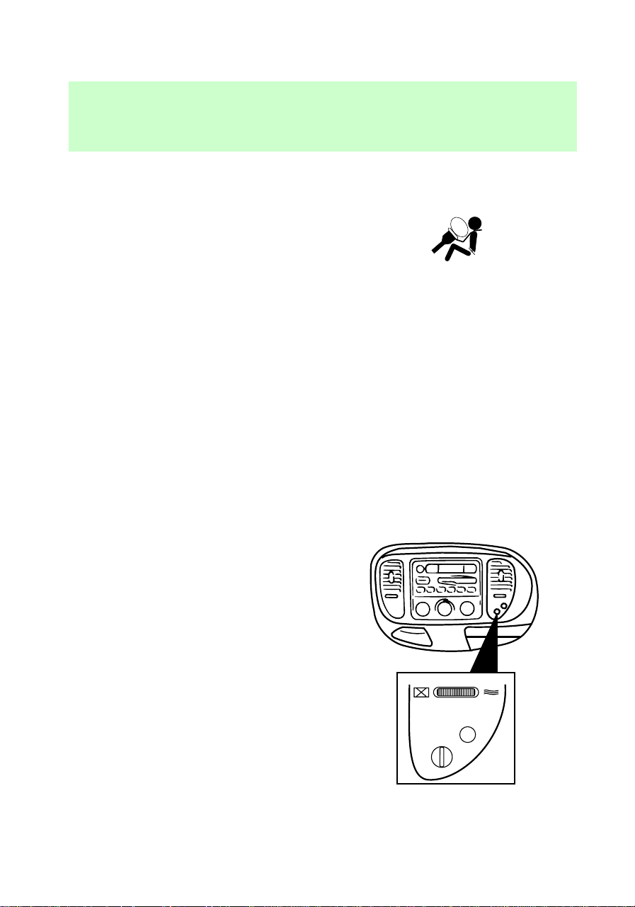
Passenger air bag deactivate
switch
Your vehicle has a passenger air
bag deactivate switch. This switch
MUST be used to activate or
deactivate the passenger air bag
whenever a rear-facing infant seat
is used in the right front or center
front passenger seat position.
PASSENGER AIRBAG
ON
OFF
OFF
f12_srs_deactivate
Seating and safety restraints
71
Keep the passenger air bag
turned on unless there is a
rear-facing infant seat installed in
the front seat. When the
passenger air bag switch is
turned off, the passenger air bag
will not inflate in a collision.
If the passenger air bag switch is
turned off, it increases the
likelihood of injury to forward
facing occupants in the passenger
seat.
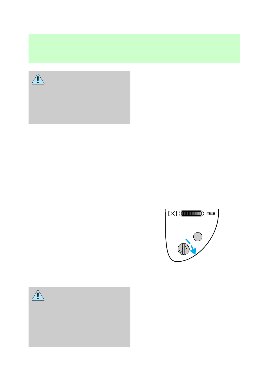
Turning the passenger air bag
off
1. Insert the ignition key, turn the
switch to OFF and remove the key.
2. The OFF light illuminates when
the key is inserted in the ignition
and turned to On. This indicates
that the passenger air bag is
deactivated.
If the light fails to
illuminate when the
passenger air bag switch is in the
OFF position and the ignition
switch is in ON, have the
passenger air bag switch serviced
at your Ford or Lincoln-Mercury
dealer immediately.
PASSENGER AIRBAG
ON
OFF
OFF
Seating and safety restraints
72
In order to avoid
inadvertent deployment of
the passenger air bag, always
remove the ignition key from the
passenger air bag deactivate
switch.
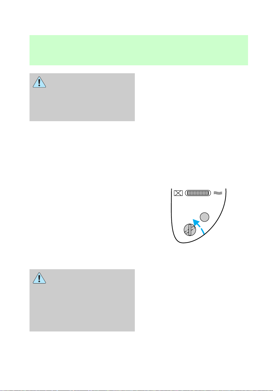
Turning the passenger air bag
back on
The passenger air bag remains off
until you turn it back on.
1. Insert the ignition key and turn
the switch to ON.
2. The OFF light will not illuminate
when the ignition is turned to On.
If the light is illuminated
when the passenger air
bag switch is in the ON position
and the ignition switch is in ON,
have the passenger air bag
switch serviced at your Ford or
Lincoln-Mercury dealer
immediately.
PASSENGER AIRBAG
ON
OFF
OFF
Seating and safety restraints
73

Keep the passenger air bag
turned on unless there is a
rear-facing infant seat installed in
the front seat. When the
passenger air bag switch is
turned off, the passenger air bag
will not inflate in a collision.
Disposal of air bags and air bag
equipped vehicles
For disposal of air bags or air bag
equipped vehicles, see your local
dealership or qualified technician.
Air bags MUST BE disposed of by
qualified personnel.
SAFETY RESTRAINTS FOR
CHILDREN
Important child restraint
precautions
You are required by law to use
safety restraints for children in the
U.S. and Canada. If small children
ride in your vehicle (generally
children who are four years old or
younger and who weigh 18 kg [40
lbs] or less), you must put them in
safety seats made especially for
children. Check your local and
state laws for specific
requirements regarding the safety
of children in your vehicle.
Never let a passenger hold
a child on his or her lap
while the vehicle is moving. The
passenger cannot protect the
child from injury in a collision.
com_disposal.01
f12_child
f12_imp_childres_prec
Seating and safety restraints
74

Always follow the instructions and
warnings that come with any infant
or child restraint you might use.
If possible, place children in the
rear seat of your vehicle. Accident
statistics suggest that children are
safer when properly restrained in
rear seating positions than when
they are restrained in front seating
positions.
Children and safety belts
Children who are too large for
child safety seats (as specified by
your child safety seat
manufacturer) should always wear
safety belts.
Follow all the important safety
restraint and air bag precautions
that apply to adult passengers in
your vehicle.
If the shoulder belt portion of a
combination lap and shoulder belt
can be positioned so it does not
cross or rest in front of the child’s
face or neck, the child should wear
the lap and shoulder belt. Moving
the child closer to the center of
the vehicle may help provide a
good shoulder belt fit.
If the shoulder belt cannot be
properly positioned:
• move the child to one of the
seats with a lap belt only (if
equipped)
OR
• if the child is the proper size,
restrain the child in a safety
seat.
com_safety_belts.01
Seating and safety restraints
75

Do not leave children,
unreliable adults, or pets
unattended in your vehicle.
To improve the fit of lap and
shoulder belts on children who
have outgrown child safety seats,
Ford recommends use of a
belt-positioning booster seat that is
labelled as conforming to all
Federal motor vehicle safety
standards. Belt-positioning booster
seats raise the child and provide a
shorter, firmer seating cushion that
encourages safer seating posture
and better fit of lap and shoulder
belts on the child. A
belt-positioning booster should be
used if the shoulder belt rests in
front of the child’s face or neck, or
if the lap belt does not fit snugly
on both thighs, or if the thighs are
too short to let the child sit all the
way back on the seat cushion
when the lower legs hang over the
edge of the seat cushion. You may
wish to discuss the special needs
of your child with your
pediatrician.
com_safety_seats.01
Seating and safety restraints
76
Child and infant or child safety
seats
Carefully follow all of the
manufacturer’s instructions
included with the safety seat you
put in your vehicle. If you do not
install and use the safety seat
properly, the child may be
injured in a sudden stop or
collision.
Ford recommends the use of a
child safety seat having a top
tether strap. Install the child safety
seat in a seating position which is
capable of providing a tether
anchorage. For more information
on top tether straps see Attaching
safety seats with tether straps in
this chapter.
When installing a child safety seat:
• Use the correct safety belt
buckle for that seating position.
• Make sure the tongue is
securely fastened in the buckle.
• Keep the buckle release button
pointing up and away from the
safety seat, with the tongue
between the child seat and the
release button, to prevent
accidental unbuckling.
• Place seatbacks in the upright
position.
• Put the safety belt in the
automatic locking mode. Refer
to Using the automatic locking
mode in this chapter.
f12_installing_seats
Seating and safety restraints
77
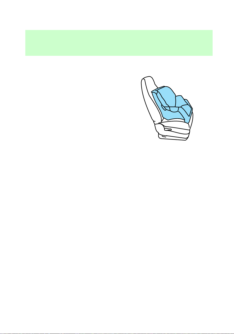
Installing child safety seats in
combination lap and shoulder
belt seating positions
1. Position the child safety seat in
a seat with a combination lap and
shoulder belt.
If you choose to install a child
safety seat in the front passenger
seat, move the seat as far back as
possible.
Seating and safety restraints
78
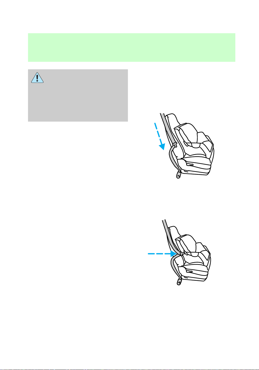
Keep the passenger air bag
turned on unless there is a
rear-facing infant seat installed in
the front seat. When the
passenger air bag switch is
turned off, the passenger air bag
will not inflate in a collision.
2. Pull down on the shoulder belt
and then grasp the shoulder belt
and lap belt together.
3. While holding the shoulder and
lap belt portions together, route
the tongue through the child seat
according to the child seat
manufacturer’s instructions. Be
Seating and safety restraints
79
sure the belt webbing is not
twisted.
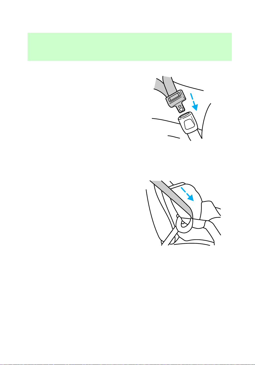
4. Insert the belt tongue into the
proper buckle for that seating
position until you hear and feel the
latch engage. Make sure the
tongue is latched securely by
pulling on it.
5. To put the retractor in the
automatic locking mode, grasp the
shoulder portion of the belt and
PRESS
Seating and safety restraints
80
pull downward until all of the belt
is extracted and a click is heard.
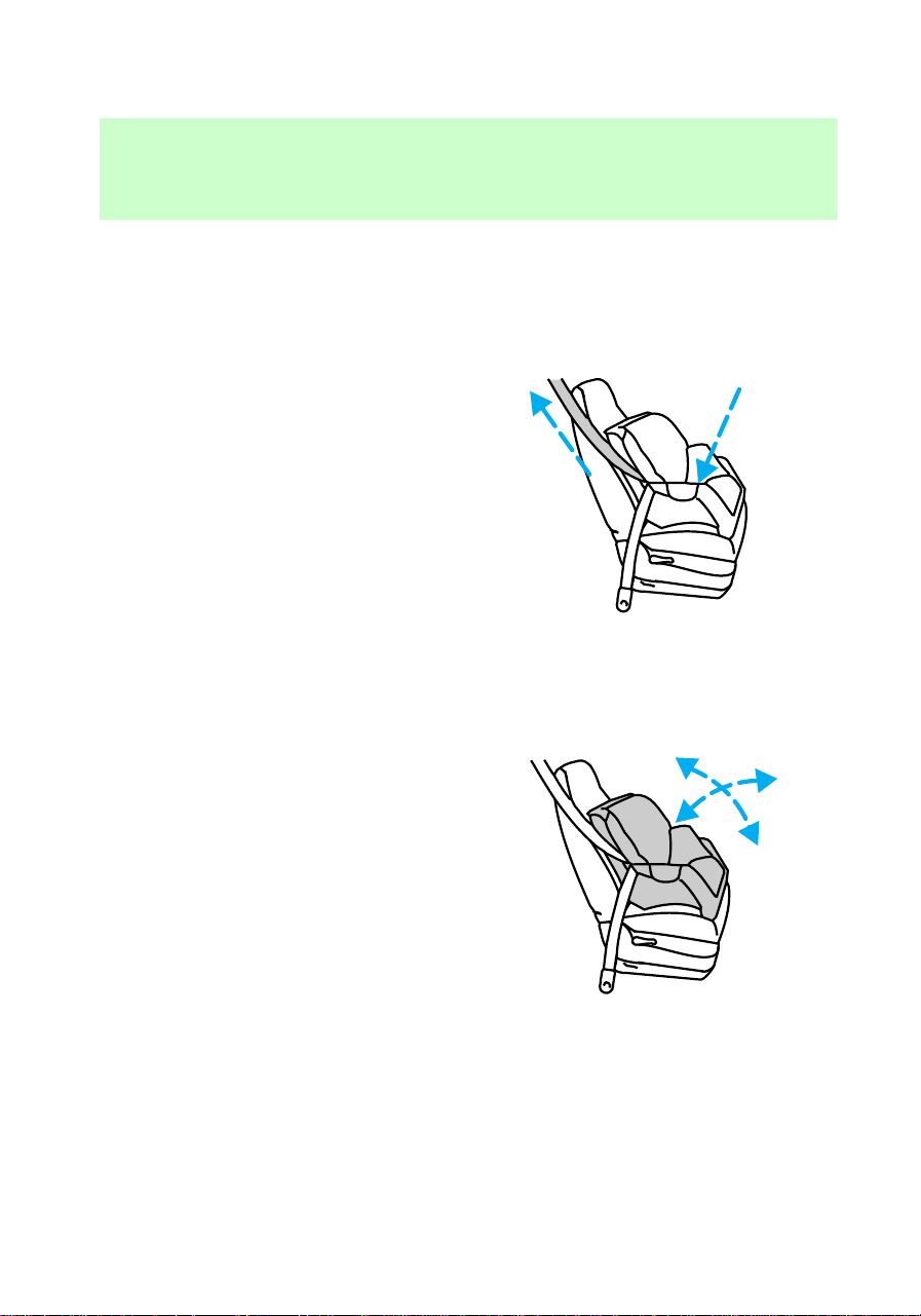
6. Allow the belt to retract. The
belt will click as it retracts to
indicate it is in the automatic
locking mode.
7. Pull the lap belt portion across
the child seat toward the buckle
and pull up on the shoulder belt
while pushing down on the child
seat.
8. Allow the safety belt to retract
to remove any slack in the belt.
9. Before placing the child in the
seat, forcibly tilt the seat forward
and back to make sure the seat is
securely held in place.
10. Try to pull the belt out of the
retractor to make sure the
retractor is in the automatic
locking mode (you should not be
Seating and safety restraints
81

able to pull more belt out). If the
retractor is not locked, unbuckle
the belt and repeat steps two
through nine.
Check to make sure the child seat is
properly secured before each use.
Using a tether strap
Ford recommends using child
safety seats with a top tether
strap. Contact the manufacturer of
your safety seat for information
about ordering a tether strap if one
is not provided to you. Contact
your Ford dealer for a free tether
strap if one is not provided to you.
Contact your Ford dealer for a free
tether anchor kit (613D74) so you
can attach a tether anchor bracket
to the back of the seat cushion. If
you have a SuperCab, attach the
bracket to the inside of the back
panel of your vehicle. Carefully
follow the instructions provided
with the kit.
If you have a SuperCab, Ford
recommends you attach tether
safety seats in a rear seating
position (if possible) with the
tether strap attached to the tether
anchor bracket as shown in the
instructions provided with the
tether anchor kit.
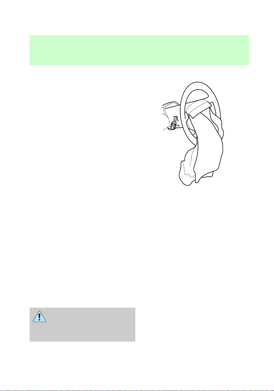
If the tethered seat is installed in
the front seat, put the tether strap
over the seatback and attach it to
the anchor bracket installed on the
rear edge of the seat cushion as
explained in the tether strap
instructions.
f12_tether_straps
Seating and safety restraints
82

STARTING YOUR VEHICLE
Important safety precautions
A computer system controls the
engine’s idle revolutions per
minute (RPM). When the engine
starts, the idle RPM runs faster to
warm the engine. If the engine idle
speed does not slow down
automatically, have the vehicle
checked. Do not allow the vehicle
to idle for more than ten minutes.
Extended idling at high
engine speeds can produce
very high temperatures in the
engine and exhaust system,
creating the risk of fire or other
damage.
Do not park, idle, or drive
your vehicle in dry grass
or other dry ground cover. The
emission system heats up the
engine compartment and exhaust
system, which can start a fire.
Do not start your vehicle
in a closed garage or in
other enclosed areas. Exhaust
fumes can be toxic. Always open
the garage door before you start
the engine. See Guarding
against exhaust fumes in this
chapter for more instructions.
com_important_precautions.05
Starting
83

If you smell exhaust fumes
inside your vehicle, have
your dealer inspect your vehicle
immediately. Do not drive if you
smell exhaust fumes.
Preparing to start the vehicle
Engine starting is controlled by the
spark ignition system. This system
meets all Canadian
Interference-Causing Equipment
standard requirements regulating
the impulse electrical field strength
of radio noise.
When starting a fuel-injected
engine, avoid pressing the
accelerator before or during
starting. Only use the accelerator
when you have difficulty starting
the engine. For more information
on starting the vehicle, refer to
Starting the vehicle in this
chapter.
Before starting the vehicle:
1. Make sure all vehicle occupants
have buckled their safety belts. For
more information on safety belts
and their proper usage, refer to
com_preparing_start.01
Starting
84
the Seating and safety restraints
chapter.
2. Make sure the headlamps and
vehicle accessories are off.
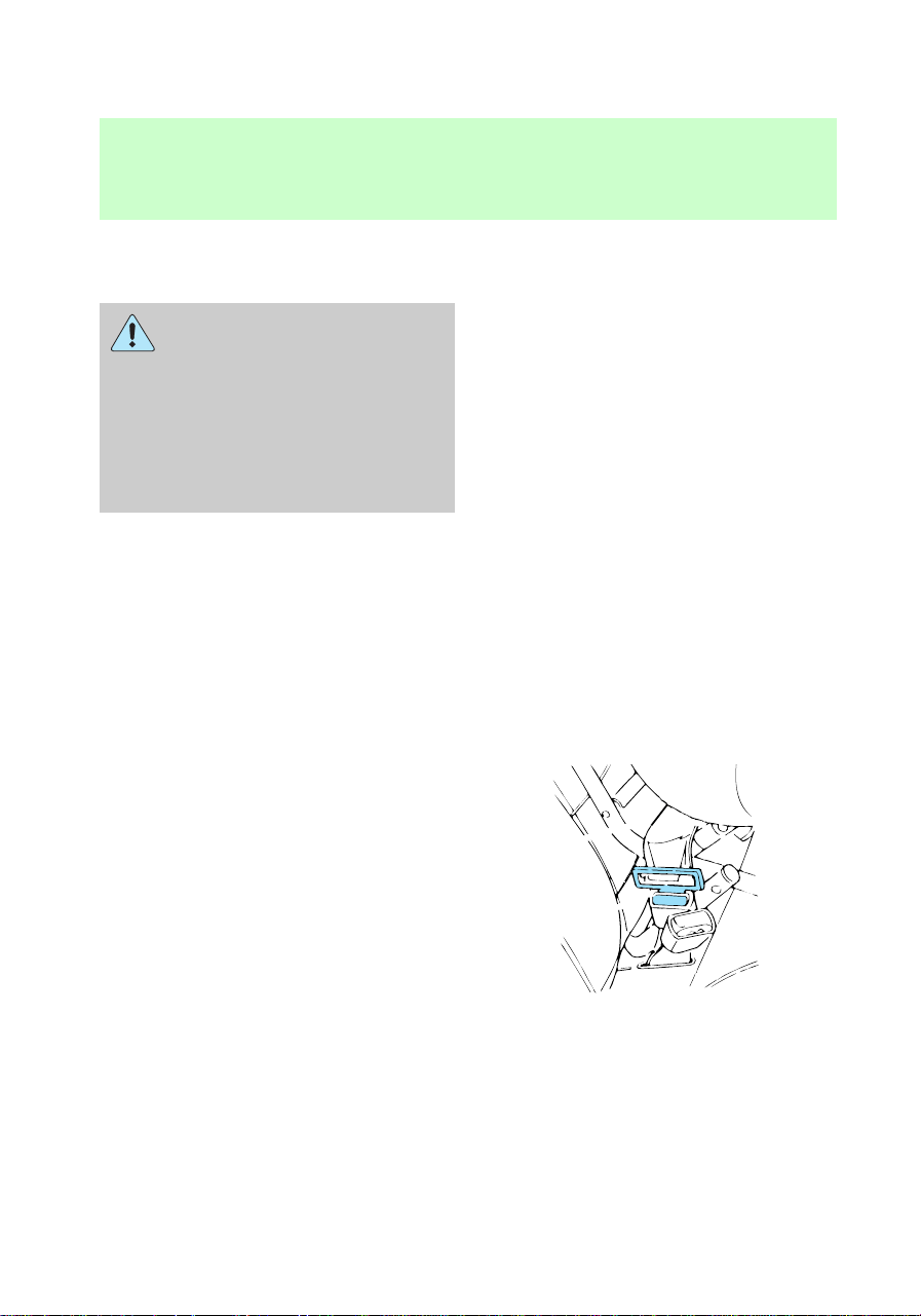
If starting a vehicle with an
automatic transmission:
• Make sure the parking brake is
set.
• Make sure the gearshift is in P
(Park).
P
Starting
85
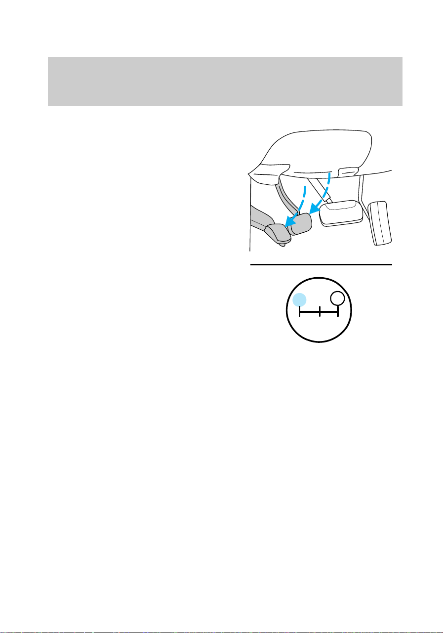
If starting a vehicle with a manual
transmission:
• Make sure the parking brake is
set.
• Push the clutch pedal to the
floor.
1
24R
3
D
Starting
86
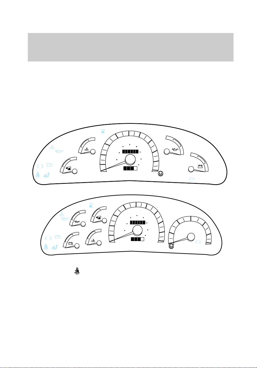
3. Turn the key to the ON position
(without turning the key to
START).
Make sure the following lights
illuminate briefly. If a light fails to
illuminate, have the vehicle
serviced.
• If the driver’s safety belt is
fastened, the
light does not
illuminate.
!
MPH
10
50
30
70
40
80
120
140
180
40
20
0
100
90
60
80
60
100
20 km/h
0010
000005
C
H
E
F
DOOR
AJAR
LOW
FUEL
MPH
CHECK
ENGINE
ABS
L
H
18
8
BRAKE
!
LOW
FUEL
ABS
BRAKE
3
MPH
10
50
30
70
40
80
120
140
180
40
20
0
100
90
60
80
60
100
20 km/h
0010
000005
2
4
5
6
0
1
L
H
C
H
E
F
8
18
RPMx1000
CHECK
ENGINE
Starting
87
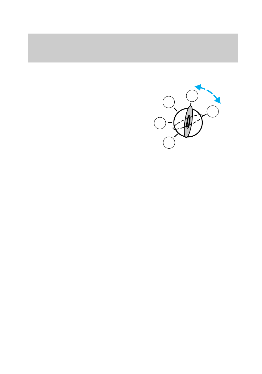
STARTING PROCEDURE
Starting the engine
1. Turn the key to 5 (Start)
without pressing the accelerator.
The key will return to 4 (On).
2. If the engine does not start
within five seconds, wait ten
seconds and try again.
3. If the engine does not start in
two attempts OR the temperature
is below —12°C (10°F), depress
accelerator and start the engine
while holding the accelerator
down. Release accelerator when
engine starts.
4. After idling for a few seconds,
apply the brake and release the
parking brake.
Using the engine block heater
(if equipped)
An engine block heater warms the
engine coolant, which improves
starting, warms up the engine
faster and allows the
heater-defroster system to respond
quickly. They are strongly
recommended if you live in a
region where temperatures reach
—23°C (–10°F) or below.
For best results, plug the heater in
at least three hours before starting
3
2
1
5
4
com_starting_vehicle.01
com_engine_heater.01
Starting
88

the vehicle. Using the heater for
longer than three hours will not
harm the engine, so the heater can
be plugged in the night before
starting the vehicle.
To prevent electrical
shock, do not use your
heater with ungrounded
electrical systems or
two-pronged (cheater) adapters.
Guarding against exhaust
fumes
Although odorless and colorless,
carbon monoxide is present in
exhaust fumes. Take precautions
to avoid its dangerous effects.
If you ever smell exhaust
fumes of any kind inside
your vehicle, have your dealer
inspect and fix your vehicle
immediately. Do not drive if you
smell exhaust fumes. These
fumes are harmful and could kill
you.
Have the exhaust and body
ventilation systems checked
whenever:
• the vehicle is raised for service
• the sound of the exhaust system
changes
• the vehicle has been damaged in
a collision
com_guarding_exhaust.01
com_ventilation_info.01
Starting
89
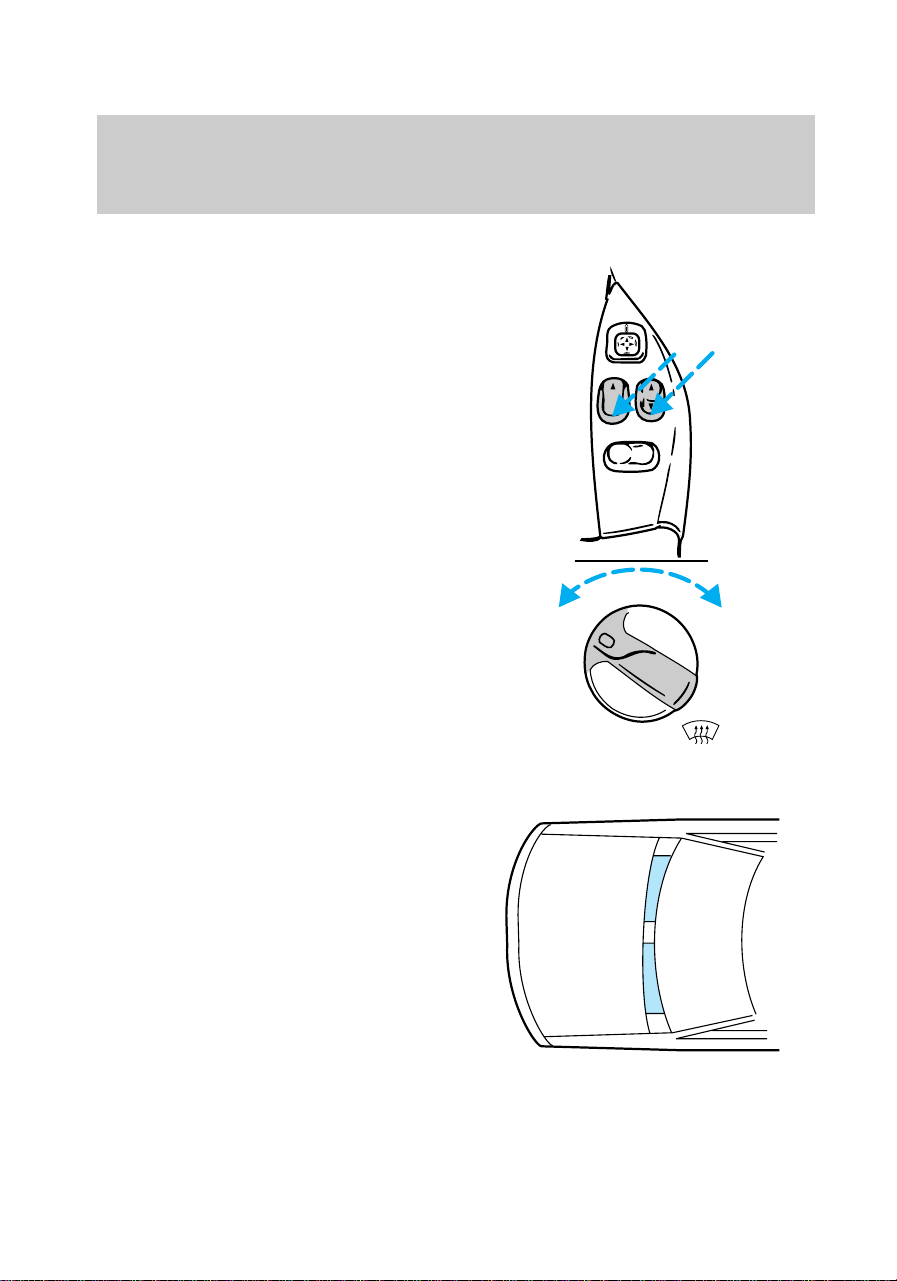
Important ventilating
information
If the engine is idling while the
vehicle is stopped in an open area
for long periods of time, open the
windows at least 2.5 cm (one
inch).
Adjust the heating or air
conditioning (if equipped) to bring
in fresh air.
Improve vehicle ventilation by
keeping all air inlet vents clear of
snow, leaves and other debris.
FLR
& DEF
MAX
A/C
FLOOR
PANEL &
FLOOR
DEF
OFF
PANEL
A/C
LU
AUTO
LR
Starting
90
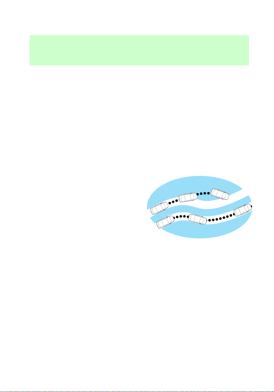
BRAKES
Rear anti-lock brake system
(ABS) (if equipped)
This system prevents one or both
rear wheels from locking up when
the brakes are applied during a
sudden stop.
Even with rear ABS, the front
brakes may lock up on any surface.
Be careful when braking, especially
on loose snow or gravel.
Anti-lock brake system (ABS) (if
equipped)
The ABS operates by detecting the
onset of wheel lock up during
brake applications and
compensating for this tendency.
The front wheels are prevented
from locking even when the brakes
are firmly applied. The
accompanying illustration depicts
the advantage of an ABS equipped
vehicle (on bottom) to a non-ABS
equipped vehicle (on top) during
hard braking.
Using ABS
• In an emergency, apply full force
on the brake. The ABS will be
activated immediately, thus
allowing you to retain full
steering control of your vehicle
and, providing there is sufficient
space, will enable you to avoid
obstacles and bring the vehicle
to a quiet stop.
• We recommend that you
familiarize yourself with this
f12_rear_abs
com_abs.01
com_using_abs.01
Driving
91

braking technique. However,
avoid taking any unnecessary
risks.
Parking brake
The parking brake should be used
whenever you park your vehicle. It
is not designed to stop a moving
vehicle. However, if the normal
brakes fail, the parking brake can
be used to stop your vehicle in an
emergency. Since the parking
brake applies only the rear brakes,
the vehicle’s stopping distance will
increase greatly and the handling
of your vehicle will be adversely
affected.
Setting the parking brake
The
!
BRAKE
light in the instrument
cluster will illuminate and remain
illuminated (when the ignition
f12_parking_brake
f12_setting_pbrake
Driving
92

switch is turned to On) until the
parking brake is released.
• Automatic and manual
transmissions – Fully depress
the parking brake pedal.
When you leave your
vehicle, place the gearshift
lever in P (Park). Set the
parking brake fully, and shut off
the engine. Never park your
vehicle in N (Neutral). If you do
not take these precautions, your
vehicle may move suddenly and
injure someone.
With the transfer case in N
(Neutral) the vehicle is free to
move with either the automatic
transmission in P (Park) or with
the manual transmission in any
driving gear.
Driving
93
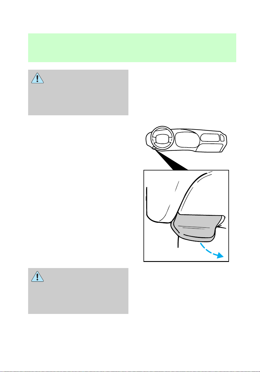
Do not leave the vehicle
unattended with the
transfer case in the N (Neutral)
position. Always set the parking
brake fully and turn off the
ignition when leaving the vehicle.
Releasing parking brake
Pull the BRAKE lever forward.
If the parking brake is fully
released, but the Brake
System light remains on, have
the brakes checked immediately.
They may not be working
properly.
TRACTION LOKT REAR AXLE
(IF EQUIPPED)
This axle provides added drive
away traction on slippery surfaces,
BRAKE
f12_releasing_pbrake
f12_traction_lok
Driving
94
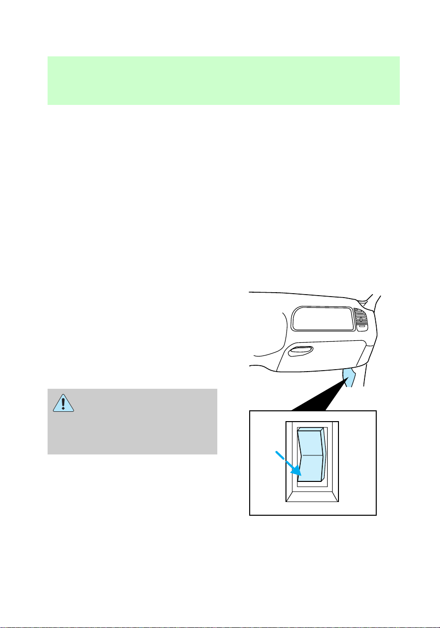
particularly when one or more
wheels are on a surface with poor
traction.
AIR SUSPENSION (IF
EQUIPPED)
The air suspension system for the
rear wheels is designed to keep
your vehicle at a constant level by
adding or releasing air from the
rear springs to compensate for
increases or decreases in vehicle
load.
Normal vehicle operation does not
require any action by the driver.
The air suspension switch is
located behind an access panel
underneath the passenger side
instrument panel.
Press the air suspension switch to
OFF when jacking or hoisting your
vehicle.
On vehicles equipped with
Air Suspension, turn OFF
the Air Suspension switch prior
to jacking, hoisting or towing
your vehicle.
OFF
f12_air_suspension
f12_transmission
Driving
95
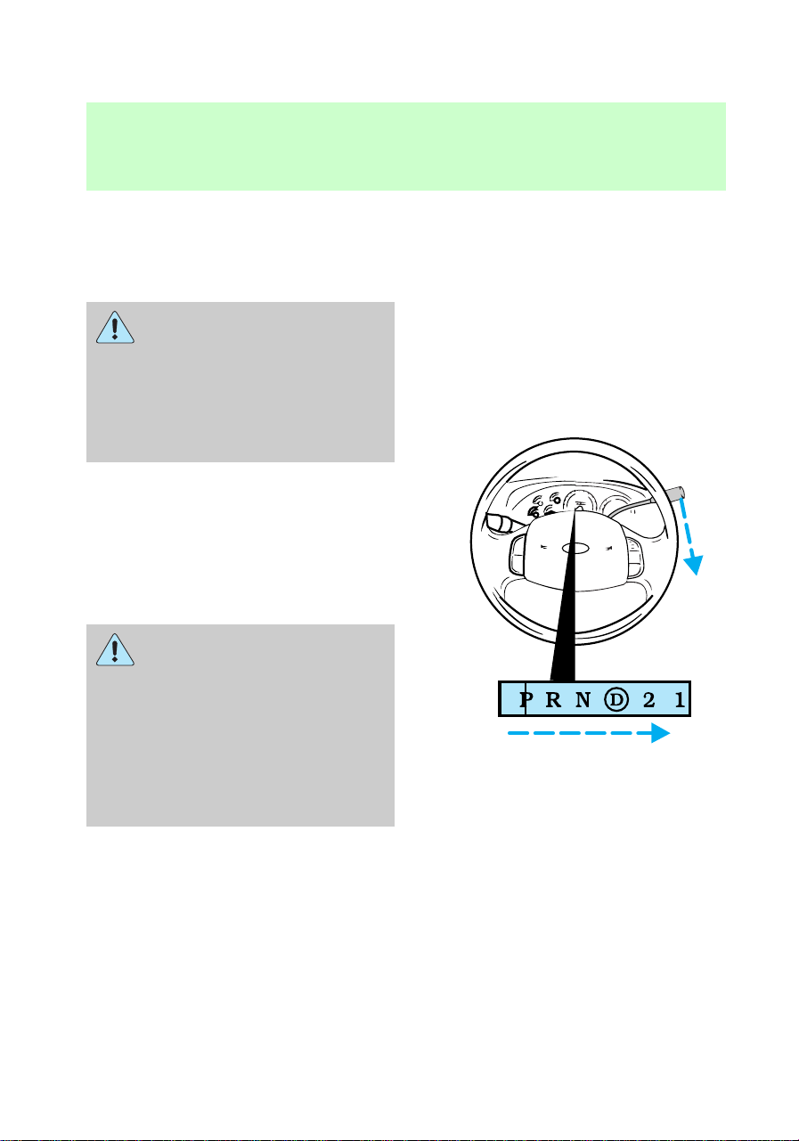
TRANSMISSION OPERATION
Automatic transmission
operation (if equipped)
Hold the brake pedal down
while you move the
gearshift lever from position to
position. If you do not hold the
brake pedal down, your vehicle
may move unexpectedly and
injure someone.
Pull the gearshift lever towards
you and downward to move the
automatic gearshift.
P (Park) – Always come to a
complete stop before shifting into
or out of P (Park).
When you leave your
vehicle, place the gearshift
lever in P (Park). Set the
parking brake fully, and shut off
the engine. Never park your
vehicle in N (Neutral). If you do
not take these precautions, your
vehicle may move suddenly and
injure someone.
R (Reverse) – Always come to a
complete stop before shifting into
or out of R (Reverse).
f12_automatic
Driving
96
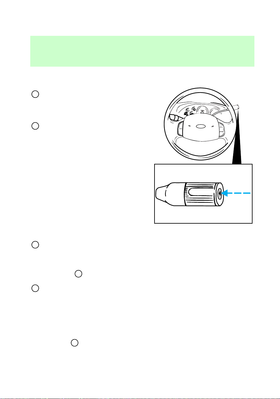
N (Neutral) – Vehicle is free to
roll.
D
(Overdrive) – The normal
driving position for the best fuel
economy. Transmission operates in
gears one through four.
D
(Overdrive) can be deactivated
by pressing the transmission
control switch on the end of the
gearshift lever. The transmission
control indicator light (TCIL)
(OFF) on the end of the gearshift
lever will remain off.
D (Drive) – Not shown on the
display. Activate by pressing the
transmission control switch on the
end of the gearshift lever. The
TCIL (OFF) will illuminate on the
gearshift lever. Transmission
operates in gears one through
three. D (Drive) provides more
engine braking than
D
(Overdrive) and is useful
whenever driving conditions (i.e.,
city traffic, hilly terrain, etc.) cause
the transmission to excessively
shift between
D
(Overdrive) and
D (Drive). Also deactivate
D
(Overdrive) when:
• driving with a heavy load
• towing a trailer up or down
steep hills
• additional engine braking is
desired.
To return to
D
(Overdrive)
mode, press the transmission
control switch. The TCIL (OFF)
will no longer be illuminated.
OVERDRIVE OFF
Driving
97
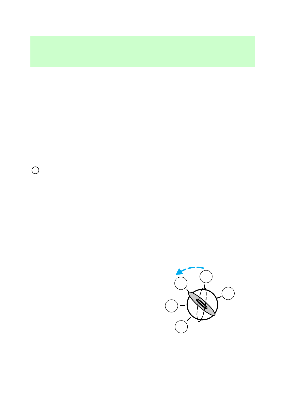
Each time the vehicle is started,
the transmission will automatically
return to normal overdrive mode.
2 (Second) – Use 2 (Second) to
start-up on slippery roads or to
provide additional engine braking
on downgrades. Transmission
operates in first and second gears.
1 (Low) – Use 1 (Low) to provide
maximum engine braking on steep
downgrades. Upshifts can be made
by shifting to 2 (Second) or to
D
(Overdrive). Selecting 1 (Low)
at higher speeds causes a shift to 2
(Second), and will shift to 1 (Low)
after vehicle decelerates to the
proper speed.
Brake-shift interlock
The brake-shift interlock feature
prevents you from shifting from P
(Park) unless the brake pedal is
depressed (with the ignition in the
On position). If you cannot move
the gearshift out of P (Park) with
the brake pedal depressed:
1. Turn ignition key to Off.
3
2
1
5
4
f12_brake_shift_interlock
Driving
98

2. Apply the parking brake.
3. Turn ignition key to Lock and
remove the key.
4. Re-insert the ignition key and
turn it to Off.
5. Shift the transmission to N
(Neutral).
6. Start the vehicle.
If you need to use the above
procedure, it is possible that a fuse
has blown and your brakelamps
may not be functioning. Refer to
the Roadside emergencies
chapter for instructions on
replacing fuses.
Do not drive your vehicle
until you verify that the
brakelamps are working.
Manual transmission operation
(if equipped)
Using the clutch
Vehicles equipped with a manual
transmission have a starter
interlock that prevents cranking
the engine unless the clutch pedal
is fully depressed.
3
2
1
5
4
f12_manual
f12_using_clutch
Driving
99
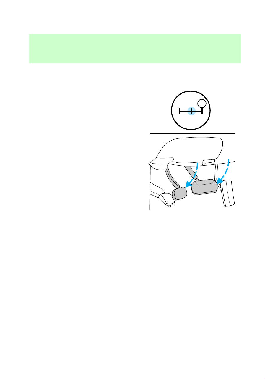
When starting a vehicle with a
manual transmission, you must:
1. Put gearshift in N (Neutral).
2. Hold down brake pedal.
1
24R
3
D
Driving
100
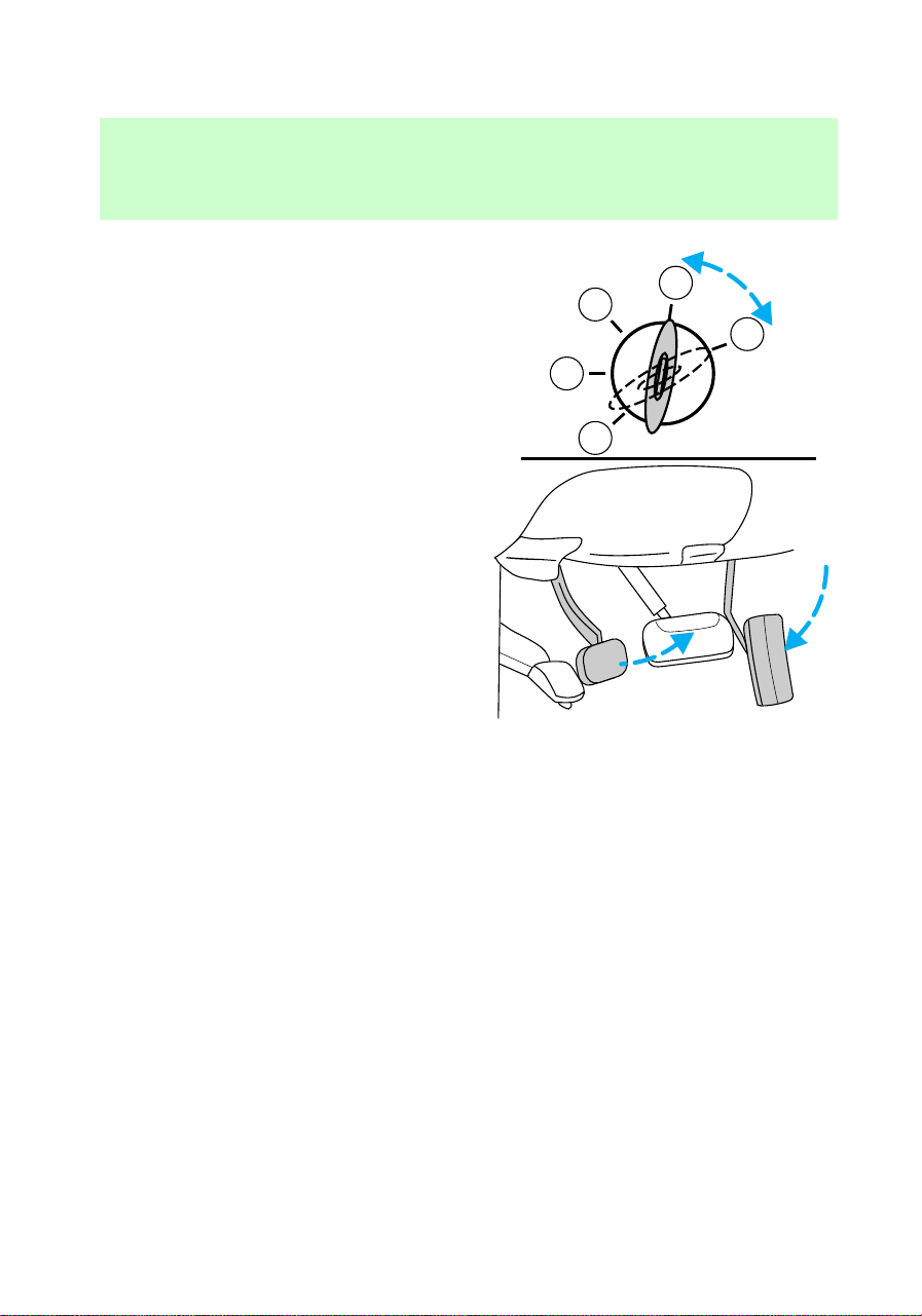
3. Depress clutch pedal.
4. Turn ignition key to Start to
start the engine and let it idle for a
few seconds.
5. Release the brake pedal.
6. Release clutch slowly while
pressing down slowly on the
accelerator pedal.
• Do not drive with your foot
resting on the clutch pedal and
do not use the clutch to hold
your vehicle at a standstill while
waiting on a hill. These actions
will seriously reduce clutch life.
Recommended shift speeds
Upshift and downshift according to
the following charts for your
specific engine/drivetrain
combination:
3
4
5
2
1
f12_shift_speeds
Driving
101
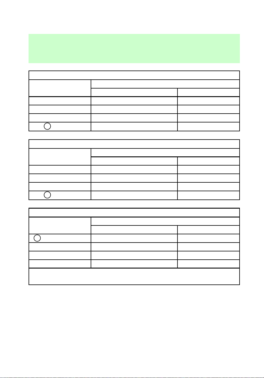
Upshifts when accelerating (recommended for best fuel economy)
Shift from: Transfer case position
1
(if equipped)
2H or 4H 4L
1 - 2 14 km/h (9 mph) 5 km/h (3 mph)
2 - 3 32 km/h (20 mph) 11 km/h (7 mph)
3 - 4 50 km/h (31 mph) 19 km/h (12 mph)
4-
D
(Overdrive) 71 km/h (44 mph) 27 km/h (17 mph)
Upshifts when cruising (recommended for best fuel economy)
Shift from: Transfer case position
1
(if equipped)
2H or 4H 4L
1 - 2 16 km/h (10 mph) 6 km/h (4 mph)
2 - 3 26 km/h (16 mph) 10 km/h (6 mph)
3 - 4 43 km/h (27 mph) 16 km/h (10 mph)
4-
D
(Overdrive) 68 kn/h (42 mph) 26 km/h (16 mph)
Maximum downshift speeds
2
Shift from: Transfer case position (if equipped)
1
2H or 4H 4L
D
(Overdrive) - 4 88 km/h (55 mph) 34 km/h (21 mph)
4 - 3 72 km/h (45 mph) 27 km/h (17 mph)
3 - 2 56 km/h (35 mph) 21 km/h (13 mph)
2 - 1 32 km/h (20 mph) 11 km/h (7 mph)
1
Use 2H or 4H for 4WD equipped vehicles.
2
Downshift at lower speeds when driving on slippery surfaces.
Driving
102
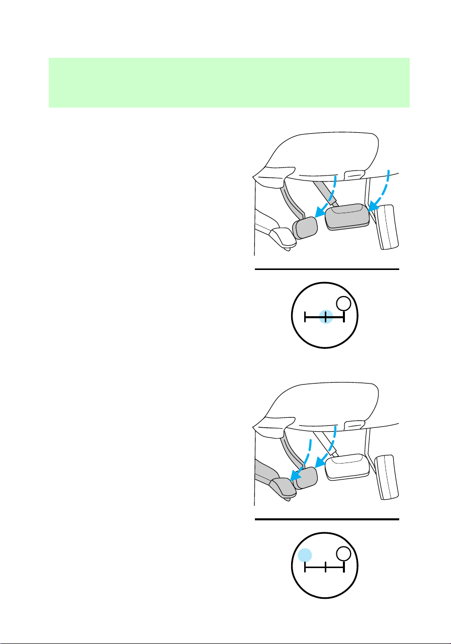
Parking your vehicle
1. Apply brake and shift into N
(Neutral).
2. Set parking brake.
3. Shift into 1 (First).
1
24R
3
D
1
24R
3
D
f12_parking
Driving
103
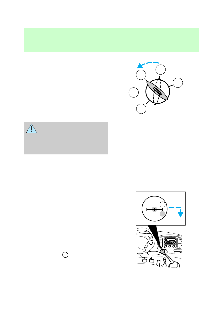
4. Turn ignition to Off.
Do not park your vehicle
in Neutral, it may move
unexpectedly and injure
someone. Use 1 (First) gear and
set the parking brake fully.
Reverse
Make sure that your vehicle is at a
complete stop before you shift into
R (Reverse). Failure to do so may
damage the transmission.
Put the gearshift in N (Neutral)
and wait at least three seconds
before shifting into R (Reverse).
You can shift into R (Reverse) only
by moving the gearshift from left
of 3 (Third) and 4 (Fourth) gears
before you shift into R (Reverse).
This is a special lockout feature
that protects you from accidently
shifting into R (Reverse) when you
downshift from
D
(Overdrive).
3
2
1
5
4
13
24R
D
f12_reverse
Driving
104

Removing key from ignition
Turn the ignition key to Lock.
Push the release lever forward
while removing the key from the
ignition.
FOUR-WHEEL DRIVE
OPERATION (4WD) (IF
EQUIPPED)
When Four–wheel drive (4WD) is
engaged, power is supplied to all
four wheels through a transfer
case. 4WD power can be selected
when additional driving power is
desired.
All utility-type vehicles and 4WD
vehicles have special design and
equipment features to make them
capable of performing in a wide
variety of off-road applications.
Specific design characteristics give
them higher centers of gravity than
ordinary passenger cars.
f12_four_wd
Driving
105

Utility and four-wheel
drive vehicles are not
designed for cornering at speeds
as high as passenger cars any
more than low-slung sports cars
are designed to perform
satisfactorily under off-road
conditions. Avoid sharp turns or
abrupt maneuvers in these
vehicles.
4WD operation is not
recommended on dry pavement.
Doing so could result in difficult
disengagement of the transfer
case, increased tire wear and
decreased fuel economy.
4WD system indicator lights
The 4WD system indicator lights
illuminate only under the following
conditions. If these lights
illuminate during normal driving,
have your vehicle serviced.
4x4
– illuminates when 4H (4WD
High) or 4L (4WD Low) is
selected.
LOW RANGE – illuminates when
4L (4WD Low) is selected.
f12_fourwd_lights
f12_using_4wd_leverop
Driving
106
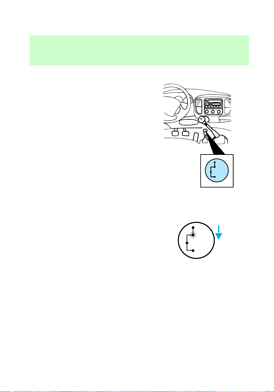
Using lever-operated 4WD
system (if equipped)
2H (2WD High) – Power to rear
axle only.
4H (4WD High) – Power to front
and rear axles.
N (Neutral) – No power to either
axle.
4L (4WD Low)– Power to front
and rear axles at reduced speed.
Shifting from 2H (2WD High) to
4H (4WD High)
Move the transfer case lever to 4H
(4WD High) at a stop or any
forward speed up to 88 km/h (55
mph).
• At temperatures below
0°C(32°F), shifts from 2H (2WD
High) to 4H (4WD High) should
not be performed above 72 km/h
(45 mph).
• Do not shift into 4H (4WD High)
with the rear wheels slipping.
2H
4H
4L
N
2H
4H
4L
N
f12_shifting_2h_4h
f12_shifting_4h_2h
Driving
107
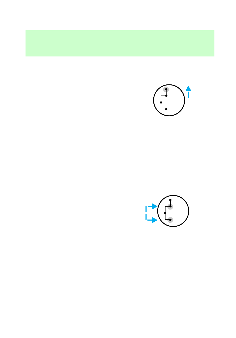
Shifting from 4H (4WD High) to
2H (2WD High)
Move the transfer case lever to 2H
(2WD High) at a stop or any
forward speed up to 88 km/h (55
mph).
Shifting from 4H (4WD High) to
4L (4WD Low)
1. Depress the brake.
2. Place the gearshift lever in N
(Neutral) (automatic transmission)
or depress the clutch (manual
transmission).
3. Pull the transfer case shift lever
through N (Neutral) directly to 4H
(4WD High) or 4L (4WD Low).
Shifting from N (Neutral) to 4H
(4WD High) or 4L (4WD Low)
With the transfer case in N
(Neutral) the vehicle is free to
move with either the automatic
transmission in P (Park) or with
the manual transmission in any
gear.
1. Stop the vehicle.
2. Depress the brake.
2H
4H
4L
N
2H
4H
4L
N
f12_shifting_4h_4l
f12_shift_n_4h4l
Driving
108
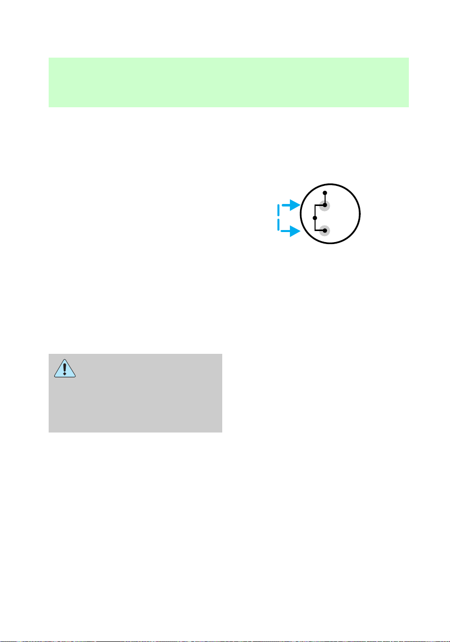
3. Place the gearshift in N
(Neutral) (automatic transmission)
or depress the clutch (manual
transmission).
4. Place the transfer case lever in
the desired gear.
Using the N (Neutral) position
This position should only be used
when towing the vehicle. Refer to
Wrecker towing in the Roadside
emergencies chapter.
Do not leave the vehicle
unattended with the
transfer case in the N (Neutral)
position. Always set the parking
brake fully and turn off the
ignition when leaving the vehicle.
2H
4H
4L
N
f12_neutral_tcase
f12_control_trac
Driving
109

Using the electronic shift 4WD
system (if equipped)
Positions of the electronic shift
system
2H (2WD High) – Power to rear
axle only.
4H (4WD High) – Power
delivered to front and rear axles
for increased traction.
4L (4WD Low) – Power to front
and rear axles at low speeds.
Shifting from 2H (2WD High) to
4H (4WD High)
Move the 4WD control to 4H at a
stop or up to 88 km/h (55 mph).
At temperatures below 0°C (32°F),
shifts from 2H to 4H should not be
performed above 72 km/h (45
mph).
• Do not shift into 4H with the
rear wheels slipping.
2H
4H
4L
2H
4H
4L
f12_ct_2h_4h
f12_ct_4h_2h
Driving
110
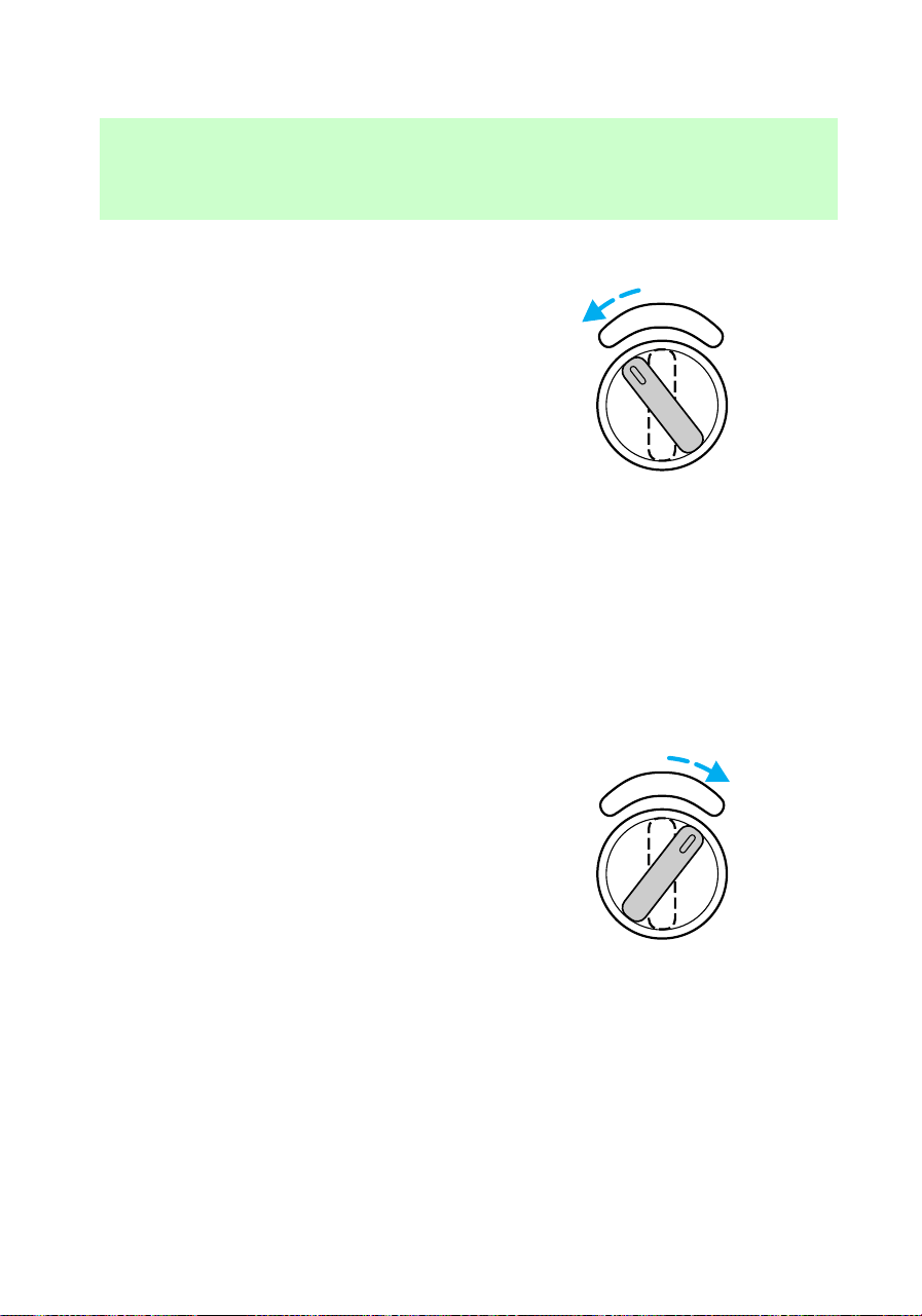
Shifting from 4H (4WD high) to
2H (2WD high)
Move the 4WD control to 2H at
any forward speed.
Shifting between 4H (4WD high)
and 4L (4WD low)
1. Bring the vehicle to a stop.
2. Depress the brake.
3. Place the gearshift in N
(Neutral) (automatic transmission)
or depress the clutch (manual
transmission).
4. Move the 4WD control to the 4H
or 4L position.
Driving off-road with 4WD
Your vehicle is specially equipped
for driving on sand, snow, mud and
rough terrain and has operating
characteristics that are somewhat
different from conventional
vehicles, both on and off the road.
The following information will help
you learn to properly use 4WD.
2H
4H
4L
2H
4H
4L
f12_ct_4h_4l
f12_driving_offroad
Driving
111

When using 4WD, maintain
steering wheel control at all times,
especially in rough terrain. Since
sudden changes in terrain can
result in abrupt steering wheel
motion, make sure you grip the
steering wheel from the outside.
Do not grip the spokes.
Drive cautiously to avoid vehicle
damage from concealed objects
such as rocks and stumps.
You should either know the terrain
or examine maps of the area
before driving. Map out your route
before driving in the area. For
more information on driving
off-road, read the “Four Wheeling”
supplement in your owner’s
portfolio.
If your vehicle gets stuck
If the vehicle is stuck, shift the
transmission in a steady motion
between forward and reverse
gears. Allow the transmission to
engage, then press lightly on the
accelerator. DO NOT rock the
vehicle for more than a few
minutes. The transmission and
tires may be damaged or the
engine can overheat.
Do not spin the wheels at
over 35 mph (55 km/h).
The tires may fail and injure a
passenger or bystander.
Sand
When driving over sand, try to
keep all four wheels on the most
f12_driving_sand
Driving
112
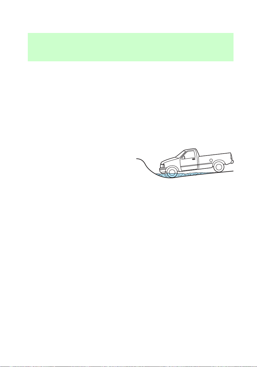
solid area of the trail. Do not
reduce the tire pressures but shift
to a lower gear and drive steadily
through the terrain. Apply the
accelerator slowly and avoid
spinning the wheels.
Mud and water
If you must drive through high
water, drive slowly. Traction or
brake capability may be limited.
When driving through water,
determine the depth; avoid water
higher than the bottom of the hubs
(if possible) and proceed slowly. If
the ignition system gets wet, the
vehicle may stall.
Once through water, always try the
brakes. Wet brakes do not stop the
vehicle as effectively as dry brakes.
Drying can be improved by moving
your vehicle slowly while applying
light pressure on the brake pedal.
After driving through mud, clean
off residue stuck to rotating
driveshafts and tires. Excess mud
stuck on tires and rotating
driveshafts causes an imbalance
f12_driving_mud_water
Driving
113
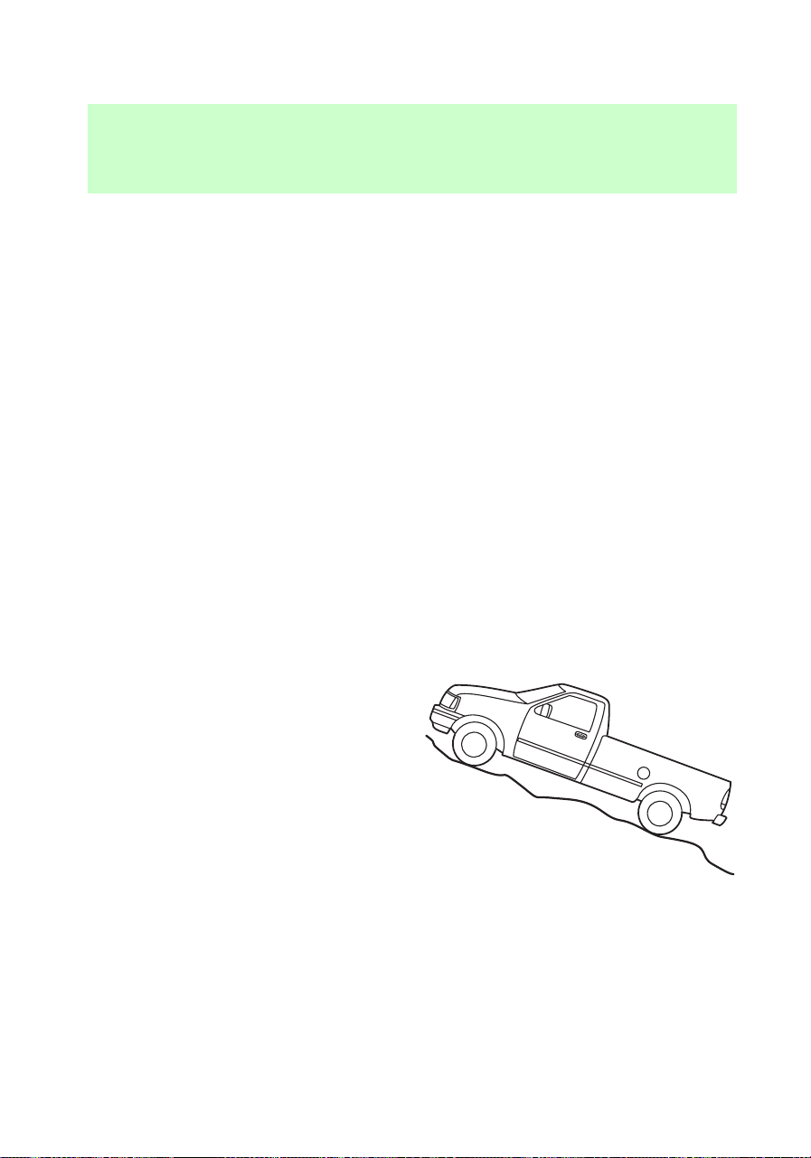
that could damage drive
components.
If the transmission and transfer
case are submerged in water, their
fluids should be checked and
changed, if necessary.
If the rear axle is submerged in
water, the rear axle lubricant
should be checked and changed, if
necessary. The rear axle is filled
with a synthetic lubricant and does
not normally require a lubricant
change for the life of the vehicle.
Rear axle lubricant quantities
should not need to be checked
unless a leak is suspected.
Driving on hill or slope terrain
When driving on a hill, avoid
driving crosswise or turning on
steep slopes. You could lose
traction and slip sideways. Drive
straight up, straight down or avoid
the hill completely. Know the
conditions on the other side of a
hill before driving over the crest.
When climbing a steep hill, start in
a lower gear rather than
downshifting to a lower gear from
a higher gear once the ascent has
started. This reduces strain on the
engine and the possibility of
stalling.
f12_driving_hill
Driving
114

When descending a steep hill,
avoid sudden braking. Rapid
pumping of the brake pedal will
help slow the vehicle and still
maintain steering control.
When speed control is on and you
are driving uphill, your vehicle
speed may drop considerably,
especially if you are carrying a
heavy load.
If vehicle speed drops more than
15–25 km/h (8–14 mph), the speed
control will cancel automatically.
Resume speed with accelerator
pedal.
If speed control cancels after
climbing the hill, reset speed by
pressing and holding the SET
ACCEL button (to resume speeds
over 50 km/h (30 mph).
Automatic transmission may shift
frequently while driving up steep
grades. Eliminate frequent shifting
by shifting out of
D
(Overdrive)
into D (Drive).
Driving on snow and ice
A 4WD vehicle has advantages
over 2WD vehicles in snow and ice
but can skid like any other vehicle.
Avoid sudden applications of
power and quick changes of
direction on snow and ice. Apply
the accelerator slowly and steadily
when starting from a full stop.
When braking, apply the brakes as
you normally would. In order to
allow the anti-lock brake system
(ABS) to operate properly, keep
f12_driving_snow_ice
Driving
115

steady pressure on the brake
pedal.
Allow more stopping distance and
drive slower than usual. Consider
using one of the lower gears.
VEHICLE LOADING
It is extremely dangerous
to ride in a cargo area,
inside or outside of a vehicle. In
a collision, people riding in these
areas are more likely to be
seriously injured or killed. Do not
allow people to ride in any area
of your vehicle that is not
equipped with seats and safety
belts. Be sure everyone in your
vehicle is in a seat and using a
safety belt properly.
Before loading a vehicle, familiarize
yourself with the following terms:
• Base Curb Weight: Weight of
the vehicle including any
standard equipment, fluids,
lubricants, etc. It does not
include passengers or
aftermarket equipment.
• Payload: Combined maximum
allowable weight of cargo,
passengers and optional
equipment. The payload equals
gross vehicle weight rating
(GVWR) minus base curb
weight.
• Gross vehicle weight (GVW):
Base curb weight plus the
payload weight (including
passengers, cargo and optional
f12_heavy_load
Driving
116

equipment. Remember, the GVW
is not a limit or a specification.
• Gross vehicle weight rating
(GVWR): Maximum total weight
of the base vehicle, passengers,
optional equipment and cargo.
The GVWR is specific to each
particular vehicle and is listed
on the Safety Compliance
Certification Label on the driver
door pillar.
• Gross axle weight rating
(GAWR): Carrying capacity for
each axle system (front and
rear). This amount is specific to
each particular vehicle and is
listed on the Safety Compliance
Certification Label on the driver
door pillar.
• Gross combined weight
rating (GCWR): Maximum
combined weight of the towing
vehicle (including passengers
and cargo) and the trailer. The
GCWR indicates the maximum
loaded weight that the vehicle is
allowed to tow.
• Maximum trailer weight:
Maximum weight of a trailer the
loaded vehicle (including
passengers and cargo) is
permitted to tow. It is
determined by subtracting the
weight of the loaded towing
vehicle from the GCWR of the
towing vehicle.
• Trailer weight range:
Specified weight range that the
trailer must fall within that
Driving
117
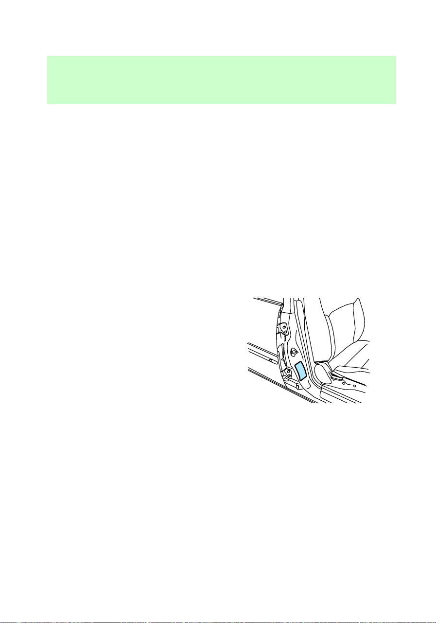
ranges from zero to the
maximum trailer weight rating.
Remember to figure in the tongue
load of your loaded trailer when
figuring the total weight.
Do not use replacement tires with
lower weight capacities than the
original because they may lower
the vehicle’s GVWR and GAWR
limitations. Replacement tires with
a higher weight limit than the
originals do not increase the
GVWR and GAWR limitations.
Calculating the load your
vehicle can carry/tow
1. Use the Safety Compliance
Certification Label to find the axle
code number and engine type for
your vehicle.
2. Use the appropriate maximum
gross combined weight rating
(GCWR) chart to find the
maximum GCWR for your type
engine and rear axle ratio.
3. Weigh your vehicle as you
customarily operate the vehicle
without cargo. To obtain correct
weights, try taking your vehicle to
a shipping company or an
inspection station for trucks.
4. Subtract your loaded vehicle
weight from the maximum GCWR
on the following charts. This is the
f12_calculating_load
Driving
118
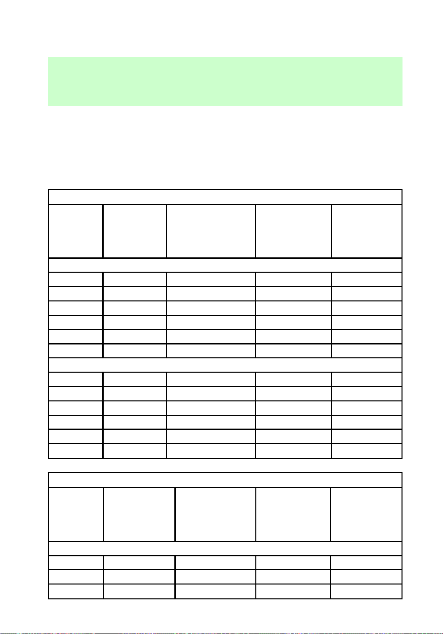
maximum trailer weight your
vehicle can tow and must fall
below the maximum shown under
maximum trailer weight on the
chart.
Trailer towing table (F-150 4x2 automatic transmission)
Engine Rear axle
ratio
Maximum
GCWR kg (lb)
Maximum
trailer weight
kg (lb)
Maximum
frontal area
of trailer
m
2
(ft
2
)
Regular Cab F-150
4.2L 3.08 4,077 (9,000) 2,177 (4,800) 5.52 (60)
4.2L 3.55 4,530 (10,000) 2,582 (5,800) 5.52 (60)
4.6L 3.08 4,530 (10,000) 2,582 (5,700) 5.52 (60)
4.6L 3.55 5,209 (11,500) 3,261 (7,200) 5.52 (60)
5.4L 3.08 4,983 (11,000) 2,948 (6,500) 5.52 (60)
5.4L 3.55 5,753 (12,700) 3,268 (8,000) 5.52 (60)
SuperCab F-150
4.2L 3.08 4,077 (9,000) 2,086 (4,600) 5.52 (60)
4.2L 3.08 4,530 (10,000) 2,540 (5,600) 5.52 (60)
4.6L 3.55 4,530 (10,000) 2,491 (5,500) 5.52 (60)
4.6L 3.55 5,209 (11,500) 3,171 (7,000) 5.52 (60)
5.4L 3.08 4,983 (11,000) 2,857 (6,300) 5.52 (60)
5.4L 3.55 5,753 (12,700) 3,628 (8,000) 5.52 (60)
Trailer towing table (F-150 4x2 manual transmission)
Engine Rear axle
ratio
Maximum
GCWR kg (lb)
Maximum
trailer weight
kg (lb)
Maximum
frontal area
of trailer
m
2
(ft
2
)
Regular Cab F-150
4.2L 3.08 2,944 (6,500) 1,041 (2,300) 5.52 (60)
4.2L 3.55 3,533 (7,800) 1,630 (3,600) 5.52 (60)
4.6L 3.08 2,944 (6,500) 997 (2,200) 5.52 (60)
Driving
119
Trailer towing table (F-150 4x2 manual transmission)
4.6L 3.55 3,533 (7,800) 1,587 (3,500) 5.52 (60)
SuperCab F-150
4.2L 3.08 2,944 (6,500) 951 (2,100) 5.52 (60)
4.2L 3.55 3,533 (7,800) 1,540 (3,400) 5.52 (60)
4.6L 3.08 2,944 (6,500) 907 (2,000) 5.52 (60)
4.6L 3.55 3,533 (7,800) 1496 (3,300) 5.52 (60)
Trailer tow table (F-150 4x4 automatic transmission)
Engine Rear axle
ratio
Maximum
GCWR kg (lb)
Maximum
trailer weight
kg (lb)
Maximum
frontal area
of trailer
m
2
(ft
2
)
Regular Cab F-150
4.2L 3.08 4,077 (9,000) 1,995 (4,400) 5.52 (60)
4.2L 3.55 4,530 (10,000) 2,449 (5,400) 5.52 (60)
4.6L 3.08 4,530 (10,000) 2,404 (5,300) 5.52 (60)
4.6L 3.55 5,209 (11,500) 3,084 (6,800) 5.52 (60)
5.4L 3.08 4,983 (11,000) 2,721 (6,000) 5.52 (60)
5.4L 3.55 5,753 (12,700) 3,492 (7,700) 5.52 (60)
SuperCab F-150
4.6L 3.08 4,530 (10,000) 2,313 (5,100) 5.52 (60)
4.6L 3.55 5,209 (11,500) 2,993 (6,600) 5.52 (60)
5.4L 3.08 4,983 (11,000) 2,721 (6,000) 5.52 (60)
5.4L 3.55 5,753 (12,700) 3,492 (7,700) 5.52 (60)
Trailer towing table (F-150 4x4 manual transmission)
Engine Rear axle
ratio
Maximum
GCWR kg (lb)
Maximum
trailer weight
kg (lb)
Maximum
frontal area
of trailer
m
2
(ft
2
)
Regular Cab F-150
4.2L 3.08 2,944 (6,500) 861 (1,900) 5.52 (60)
Driving
120
Trailer towing table (F-150 4x4 manual transmission)
4.2L 3.55 3,533 (7,800) 1,451 (3,200) 5.52 (60)
4.6L 3.08 2,944 (6,500) 816 (1,800) 5.52 (60)
4.6L 3.55 3,533 (7,800) 1,406 (3,100) 5.52 (60)
SuperCab F-150
4.6L 3.08 2,944 (6,500) 771 (1,700) 5.52 (60)
4.6L 3.55 3,533 (7,800) 1,360 (3,000) 5.52 (60)
Trailer towing table (F-250 4x2 automatic transmission)
Engine Rear axle
ratio
Maximum
GCWR kg (lb)
Maximum
trailer weight
kg (lb)
Maximum
frontal area
of trailer
m
2
(ft
2
)
Regular Cab F-250
4.6L 3.31 4,756 (10,500) 2,630 (5,800) 5.52 (60)
4.6L 3.73 5,436 (12,000) 3,311 (7,300) 5.52 (60)
5.4L 3.31 5,436 (12,000) 3,265 (7,200) 5.52 (60)
5.4L 3.73 6,115 (13,500) 3,946 (8,600) 5.52 (60)
SuperCab F-250
4.6L 3.31 4,756 (10,500) 2,585 (5,700) 5.52 (60)
4.6L 3.73 5,436 (12,000) 3,265 (7,200) 5.52 (60)
5.4L 3.31 5,436 (12,000) 3,220 (7,100) 5.52 (60)
5.4L 3.73 6,115 (13,500) 3,900 (8,600) 5.52 (60)
Trailer towing table (F-250 4x2 manual transmission)
Engine Rear axle
ratio
Maximum
GCWR kg (lb)
Maximum
trailer weight
kg (lb)
Maximum
frontal area
of trailer
m
2
(ft
2
)
Regular Cab F-250
4.6L 3.31 3,261 (7,200) 1,179 (2,600) 5.52 (60)
4.6L 3.73 3,533 (7,800) 1,451 (3,200) 5.52 (60)
SuperCab F-250
Driving
121
Trailer towing table (F-250 4x2 manual transmission)
4.6L 3.31 3,261 (7,200) 1,133 (2,500) 5.52 (60)
4.6L 3.73 3,533 (7,800) 1,406 (3,100) 5.52 (60)
Trailer towing table (F-250 4x4 automatic transmission)
Engine Rear axle
ratio
Maximum
GCWR kg (lb)
Maximum
trailer weight
kg (lb)
Maximum
frontal area of
trailer m
2
(ft
2
)
Regular Cab F-250
4.6L 3.31 4,756 (10,500) 2,449
(5,400)
5.52 (60)
4.6L 3.73 5,436 (12,000) 3,129
(6,900)
5.52 (60)
5.4L 3.31 5,436 (12,000) 3,084
(6,800)
5.52 (60)
5.4L 3.73 6,115 (13,500) 3,764
(8,300)
5.52 (60)
SuperCab F-250
4.6L 3.31 4,756 (10,500) 2,449
(5,400)
5.52 (60)
4.6L 3.73 5,436 (12,000) 3,129
(6,900)
5.52 (60)
5.4L 3.31 5,436 (12,000) 3,084
(6,800)
5.52 (60)
5.4L 3.73 6,115 (13,500) 3,764
(8,300)
5.52 (60)
Trailer towing table (F-250 4x4 manual transmission)
Engine Rear axle
ratio
Maximum
GCWR kg (lb)
Maximum
trailer weight
kg (lb)
Maximum
frontal area of
trailer m
2
(ft
2
)
Regular Cab F-250
4.6L 3.31 3,261 (7,200) 952 (2,100) 5.52 (60)
Driving
122
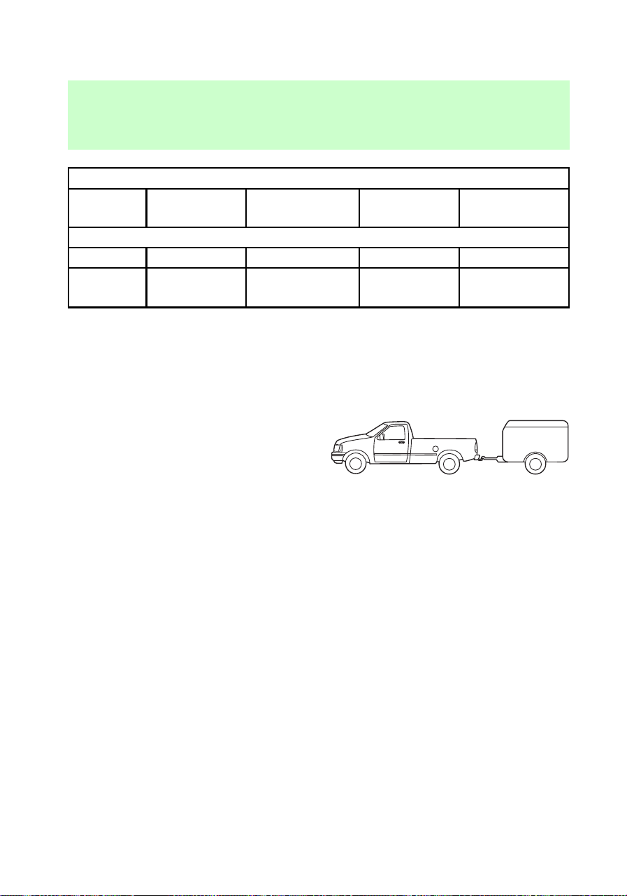
Trailer towing table (F-250 4x4 manual transmission)
4.6L 3.73 3,533 (7,800) 1,224
(2,700)
5.52 (60)
SuperCab F-250
4.6L 3.31 3,261 (7,200) 952 (2,100) 5.52 (60)
4.6L 3.73 3,533 (7,800) 1,224
(2,700)
5.52 (60)
TOWING A TRAILER
Your vehicle may tow a class I, II
or III trailer provided the
maximum trailer weight is less
than or equal to the maximum
trailer weight listed for your engine
and rear axle ratio on the above
charts.
Your vehicle’s load capacity is
designated by weight, not by
volume, so you cannot necessarily
use all available space when
loading a vehicle.
Towing a trailer places an
additional load on your vehicle’s
engine, transmission, axle, brakes,
tires and suspension. Inspect these
components carefully after any
towing operation.
f12_trailer
Driving
123
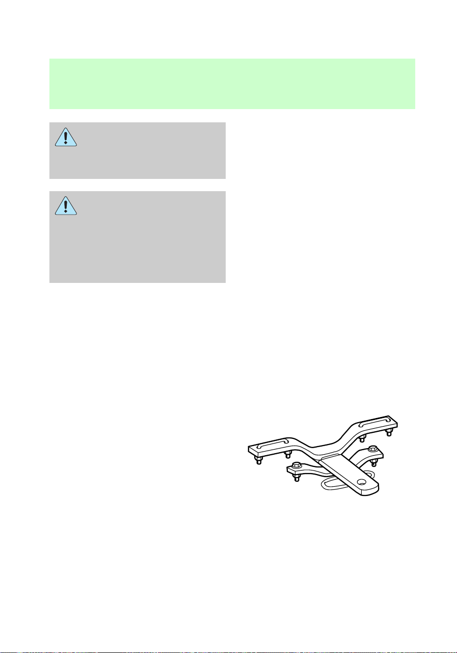
Do not exceed the GVWR
or the GAWR specified on
the Safety Compliance
Certification Label.
Towing trailers beyond the
maximum recommended
gross trailer weight could result
in engine damage,
transmission/axle damage,
structural damage, loss of
control, and personal injury.
Preparing to tow
Use the proper equipment for
towing a trailer, and make sure it
is properly attached to your
vehicle. See your dealer or a
reliable trailer dealer if you require
assistance.
Hitches
Do not use or install hitches that:
• clamp onto the vehicle bumper
• attach to the axle.
Underbody hitches are acceptable
if installed properly.
Distribute the load so that only 10
to 15% of the total is on the
tongue. Tie down the load so that
it does not shift and change the
weight on the hitch.
f12_preparing_tow
f12_hitches
Driving
124

Using a load-equalizing hitch
When hooking up a trailer using a
load-equalizing hitch, always use
the following procedure.
1. Park the unloaded vehicle on a
level surface. With the ignition on
and all doors closed, allow the
vehicle to stand for several
minutes so that it can level.
2. Turn the air suspension switch
to OFF (if equipped).
3. Measure the height of a
reference point on the front and
rear bumpers at the center of the
vehicle.
4. Attach the trailer to the vehicle
and adjust the hitch equalizers so
that the front bumper height is
0–13 mm (0.5 in). After proper
adjustment, the rear bumper
should be no higher than in step 3.
5. Turn on the air suspension
switch.
Adjusting an equalizing
hitch so the rear bumper
of the vehicle is lower or higher
than it was unloaded will defeat
the function of the load
equalizing hitch and may cause
unpredictable handling.
Step bumper (if equipped)
Step bumpers have a built-in hitch
and only require a ball with a 2.5
cm (1 in.) shank diameter. Step
bumpers have a Class III capability
(2,270 kg [5,000 lb] trailer weight
and 91 kg [200 lb] tongue weight.
f12_step_bumper
Driving
125

If it is necessary to relocate the
trailer hitch ball position, a
frame-mounted trailer hitch must
be installed.
Safety chains
Always use safety chains between
your vehicle and trailer. Cross
chains under the trailer tongue and
allow slack for turning corners.
Connect safety chains to the
vehicle frame or hook retainers.
Never attach chains to the bumper.
Trailer brakes
Trailer brakes are required on
most towed vehicles weighing over
680 kg (1,500 lbs).
Do not connect a trailer’s
hydraulic brake system
directly to your vehicle’s brake
system. Your vehicle may not
have enough braking power and
your chances of having a
collision greatly increase.
Trailer lamps
Trailer lamps are required on most
towed vehicles. Make sure your
trailer lamps conform to Federal
and local regulations. See your
dealer or trailer rental agency for
the proper instructions and
equipment for hooking up trailer
lamps.
Driving while you tow
Do not drive faster than 88 km/h
(55 mph) while towing a trailer. Do
not drive faster than 72 km/h (45
f12_safety_chains
f12_trailer_brakes
f12_trailer_lamps
f12_driving_towing
Driving
126
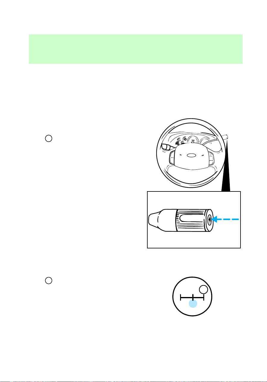
mph) with a trailer while towing in
hilly country or on hot days.
Speed control may shut off if you
are towing on very long, steep
grades.
When towing a trailer
If equipped with an automatic
transmission, use D (Drive) rather
than
D
(Overdrive) while towing
up or down steep hills. This will
eliminate excessive downshifting
and upshifting for optimum fuel
economy and transmission cooling.
If equipped with a manual
transmission, use 4 (Fourth) rather
than
D
(Overdrive).
• Anticipate stops and brake
gradually.
OVERDRIVE OFF
1
24R
3
D
f12_when_you_tow
Driving
127

• Allow more room for stopping
with a trailer attached.
• Practice turning, stopping and
backing in an area before
starting on a trip to get the feel
of the vehicle/trailer
combination.
• When turning, drive slightly
beyond the normal turning point
so the trailer wheels will clear
curbs and other obstacles.
• When stopped in traffic for long
periods of time in hot weather,
place the automatic transmission
gearshift in P (Park) to increase
idle speed. This aids engine
cooling and air conditioner
efficiency.
• Vehicles with trailers should not
be parked on a grade. If you
must park on a grade, place
wheel chocks under the trailer’s
wheels.
• After you have travelled about
80 km (50 miles), thoroughly
check your hitch, electrical
connections and trailer wheel
lug nuts.
Launching or retrieving a boat
When backing down a ramp during
boat launching or retrieval,
• Do not allow the static water
level to rise above the bottom
edge of the rear bumper and
• Do not allow waves to break
higher than 15 cm (six inches)
above the bottom edge of the
rear bumper.
com_launch-retrieving_boat.01
Driving
128

Exceeding these limits may allow
water to enter critical vehicle
components, adversely affecting
driveability, emissions and
reliability.
Servicing when towing
If you tow a trailer for long
distances, your vehicle will require
more frequent service intervals.
Refer to the “Service Guide” for
more information.
SNOWPLOWING
Ford recommends the following
specifications for low speed,
personal use snow removal:
• F-150 4WD long wheelbase or
F-250 4WD Regular Cab
• 4.6L or 5.4L engine
• Super engine cooling
• Heavy duty front suspension
package
• Automatic transmission with
auxiliary automatic transmission
fluid cooling
• All-terrain tires
Do not install a snowplow and
plow with your vehicle until it has
been driven at least 800 km (500
miles).
Installing snowplow
Read the following instructions
before installing a snowplow:
• Front GAWR must not exceed
63% of the GVW. Add ballast
weight to the back of the
f12_service_towing
f12_snowplowing
f12_install_plow
Driving
129

vehicle, if necessary. Refer to
the Safety Compliance
Certification Label to find Front
GAWR.
• The Front Axle Accessory
Reserve Capacity and the Total
Accessory Reserve Capacity
listed on the bottom right of the
Safety Compliance Certification
Label will determine whether or
not the addition of a snowplow
will overload your vehicle.
• The weight of the snowplow and
supporting components
distributed to the front axle
must not exceed the front
accessory reserve capacity.
• The total weight of the
snowplow and aftermarket
equipment must not exceed the
Total Accessory Reserve
Capacity.
• The weight of the installed
snowplow and aftermarket
equipment must not load the
vehicle beyond the GAWR and
GVWR listed on the Safety
Compliance Certification Label.
• Federal and most local
regulations require additional
exterior lamps for
snowplow-equipped vehicles.
Consult your dealer for
additional information.
• After installing a snowplow to
the vehicle, ensure the vehicle’s
front toe alignment and front
ride height are within
specification (reset if required).
Driving
130
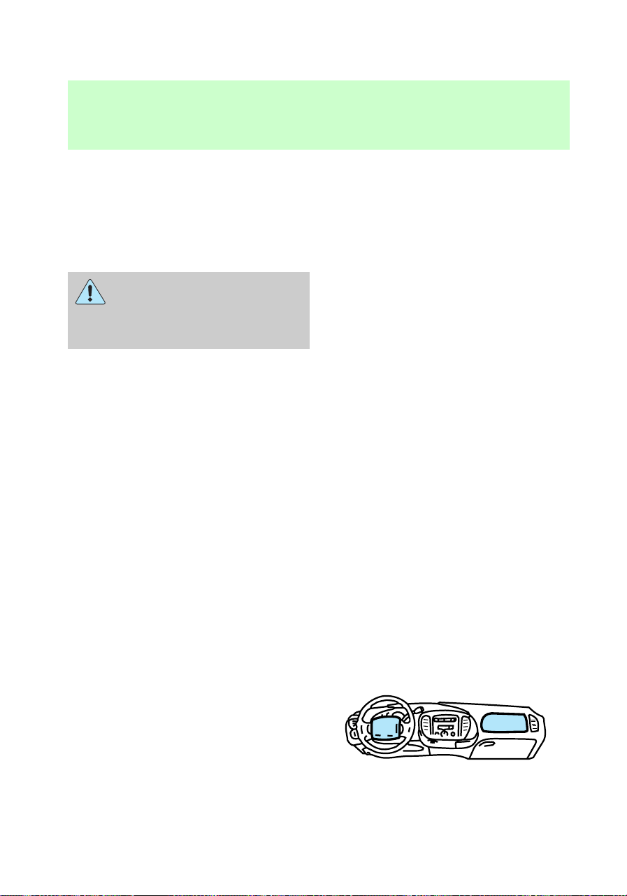
These specifications are located
in the vehicle’s Service Manual.
Adherence to the toe and ride
height specification is important
for proper tire wear, ride,
handling and headlight aim.
Do not exceed the GVWR
or the GAWR specified on
the Safety Compliance
Certification Label.
Removing snowplow
Read the following instructions
before removing a snowplow:
• After removing a snowplow from
the vehicle, ensure the vehicle’s
front toe alignment and front
ride height are within
specification (reset if required).
These specifications are located
in the vehicle’s Service Manual.
Adherence to the toe and ride
height specification is important
for proper tire wear, ride,
handling and headlight aim.
Snowplowing with your air bag
equipped vehicle
Your vehicle is equipped with
driver and passenger air bags. The
air bags are designed to deploy in
a collision with a solid barrier at a
range of 13 to 23 km/h (8 to 14
mph) or a parked car at a range of
25 to 45 km/h (16 to 28 mph).
f12_remove
f12_snowplow_srs
Driving
131

Careless or high speed driving
while plowing snow which results
in vehicle decelerations equivalent
to or greater than the air bag
deployment impact speeds listed
above can deploy the air bag. Such
driving also increases the risk of
accidents.
All occupants of the
vehicle, including the
driver, should always wear their
safety belts.
Never remove or defeat the
“tripping mechanisms” designed
into the snow removal equipment
by its manufacturer. Doing so may
cause damage to the vehicle and
the snow removal equipment as
well as possible air bag
deployment.
Do not attempt to service,
repair, or modify the Air
Bag Supplemental Restraint
System or its fuses. See your
Ford or Lincoln-Mercury dealer.
Engine temperature while
plowing
When driving with a plow, your
engine may run at a higher
temperature than normal because
the attached snowplow blade will
restrict airflow to the radiator.
C
H
C
H
f12_driving_wplow
Driving
132

If you are driving more then 24 km
(15 miles) at temperatures above
freezing, angle the plow blade
either full left or full right to
provide maximum airflow to the
radiator.
If you are driving less than 24 km
(15 miles) at speeds up to 64 km/h
(40 mph) in cold weather, you will
not need to worry about blade
position to provide maximum
airflow.
Transmission operation while
plowing
• Shift transfer case to 4L (4WD
Low) when plowing in small
areas at speeds below 8 km/h (5
mph).
• Shift transfer case to 4H (4WD
High) when plowing larger areas
or light snow at higher speeds.
Do not exceed 24 km/h (15
mph).
• Do not shift the transmission
from a forward gear to R
(Reverse) until the engine is at
idle and the wheels are stopped.
• If the vehicle is stuck, shift the
transmission in a steady motion
between forward and reverse
gears. Do not rock the vehicle
for more than a few minutes.
The transmission and tires may
be damaged or the engine can
overheat.
Driving
133

Do not spin the wheels at
over 35 mph (55 km/h).
The tires may fail and injure a
passenger or bystander.
FUEL CONSUMPTION
Fuel economy can be improved by
avoiding:
• lack of regular, scheduled
maintenance
• excessive speed
• rapid acceleration.
f12_fuel_consumption
Driving
134
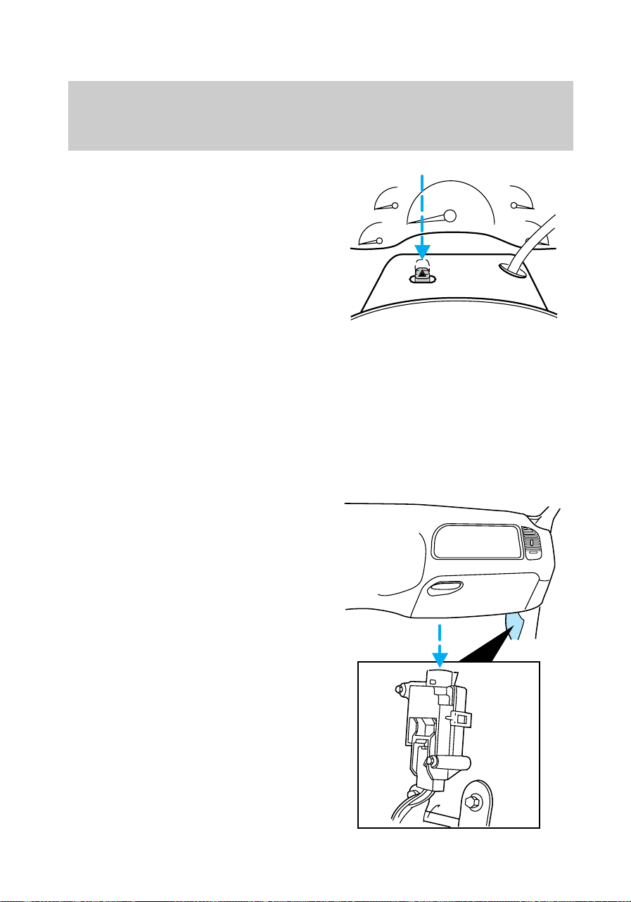
HAZARD LIGHTS CONTROL
Use only in an emergency to warn
traffic of vehicle breakdown,
approaching danger, etc. Depress
to activate all indicators
simultaneously. Depress again to
switch off. The warning lights can
be operated when the ignition is
off.
FUEL PUMP SHUT-OFF SWITCH
If the engine cranks but does not
start after a collision, the fuel
pump shut–off switch may have
been activated. The shut–off
switch is a device intended to stop
the electric fuel pump when your
vehicle has been involved in a
substantial jolt.
1. Turn the ignition switch to the
OFF position.
2. Check fuel system for leaks.
3. If no fuel leak is apparent, reset
the fuel pump shut-off switch by
pushing in the button on the
switch.
4. Turn the ignition switch to the
ON position. Pause for a few
seconds and return the key to the
OFF position.
5. Make a further check for leaks
in the fuel system.
com_hazard_switch.01
com_fuel_shut-off.01
f12_fuses
Roadside emergencies
135
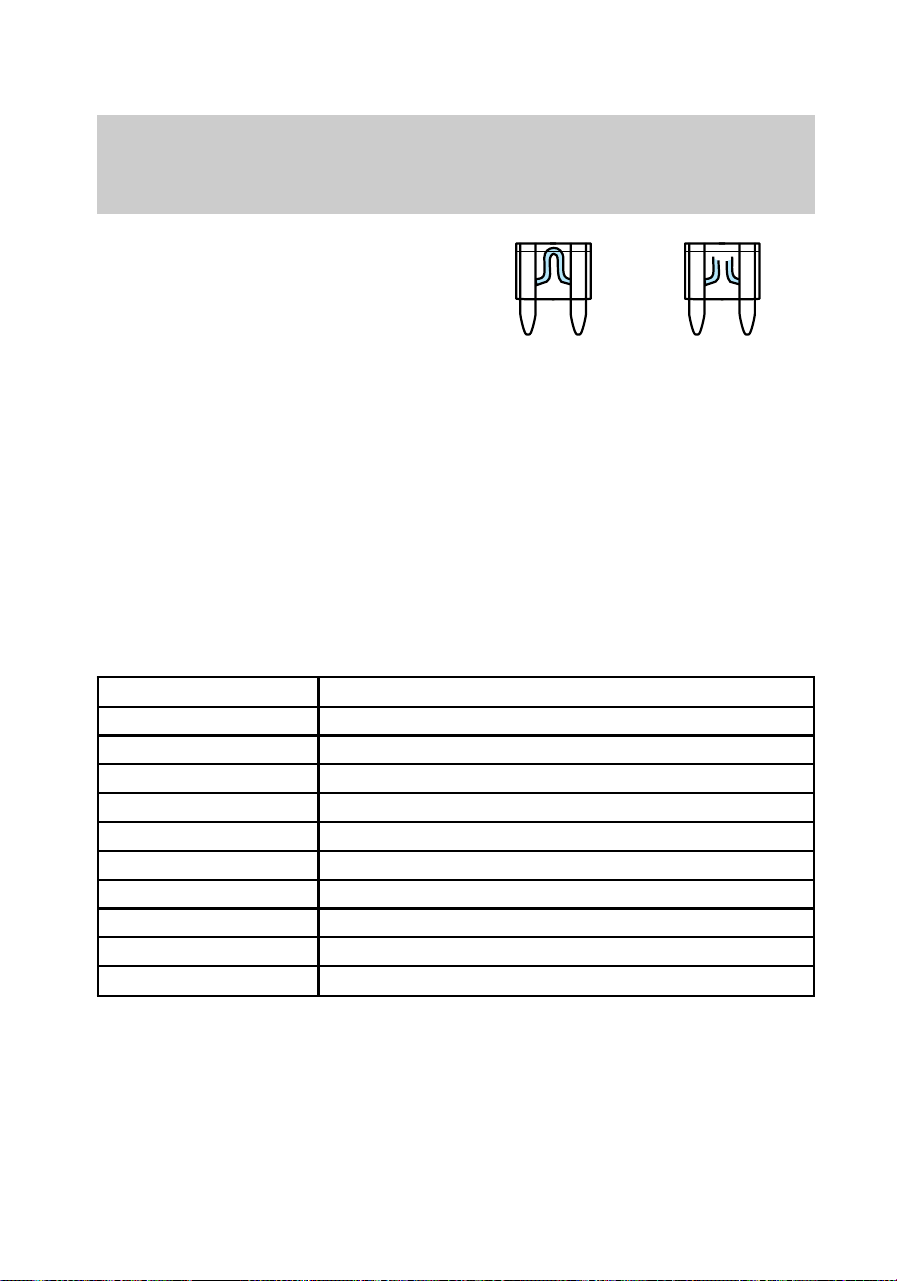
REPLACING BLOWN FUSES
If electrical components in the
vehicle are not working, a fuse
may have blown. Blown fuses are
identified by a broken element.
Check the appropriate fuses before
replacing any electrical
components.
Even after a fuse is replaced, it
may continue to blow if the cause
of the overload is not identified
and corrected. If a fuse continues
to blow, have the vehicle’s
electrical system checked.
Standard fuse amperage ratings
and colors
Fuse rating Color
7.5 amp Brown
10 amp Red
15 amp Blue
20 amp Yellow
30 amp Light green
30 amp fuse link Pink
40 amp Green
60 amp fuse link Yellow
80 amp fuse link Black
100 amp fuse link Blue
Roadside emergencies
136

Instrument panel fuses
Always replace a fuse with
one that has the specified
amperage rating. Using a fuse
with a higher amperage rating
can cause severe wire damage
and could start a fire.
Position Amps Description
1 15 Stop/turn lamps and turn indicators
2 5 Instrument cluster
3 25 Cigarette lighter
4 5 Power mirrors, autolamp, remote
anti-theft/keyless entry, headlamp relay and
parking lamp relay
5 15 Speed control, daytime running lamps, climate
control blend door, backup lamps, A/C clutch
coil
6 5 Brake-shift interlock, generic electronic module
(GEM)/central timer module (CTM) and air
suspension module
7 - Not used
8 5 Radio, remote anti-theft/keyless entry, GEM
module/CTM module
1
1
2
3
4
5
12 22
21323
31424
4
16
15
25
526
61727
71828
81929
11 21 31
930
10 20
f12_pass_comp_fuses
Roadside emergencies
137
Position Amps Description
9 - Not used
10 - Not used
11 30 Wiper system
12 5 On-board diagnostic (OBD II) data link
connector
13 15 Brake ON/OFF switch, rear anti-lock brake
module and brake pressure switch
14 15 Interior lamps and accessory delay relay
15 5 GEM module/CTM module
16 20 High beam headlamps
17 - Not used
18 5 Instrument illumination
19 10 Air bag diagnostic monitor, instrument cluster
20 5 GEM module/CTM module and powertrain
control module (PCM)
21 15 Starter relay
22 10 Air bag diagnostic monitor and passenger air
bag deactivate switch
23 10 4WD clutch relay, electronic flasher, 4WD/2WD
vacuum solenoids and trailer tow battery charge
relay
24 10 I/P blower relay
25 5 4WABS module and relay
26 10 Right low beam headlamp and DRL module
27 5 Foglamp relay
28 10 Left low beam headlamp
29 5 Autolamp, instrument cluster, transmission
control indicator lamp and switch
30 30 Ignition coils and PCM relay
31 - Not used
Roadside emergencies
138
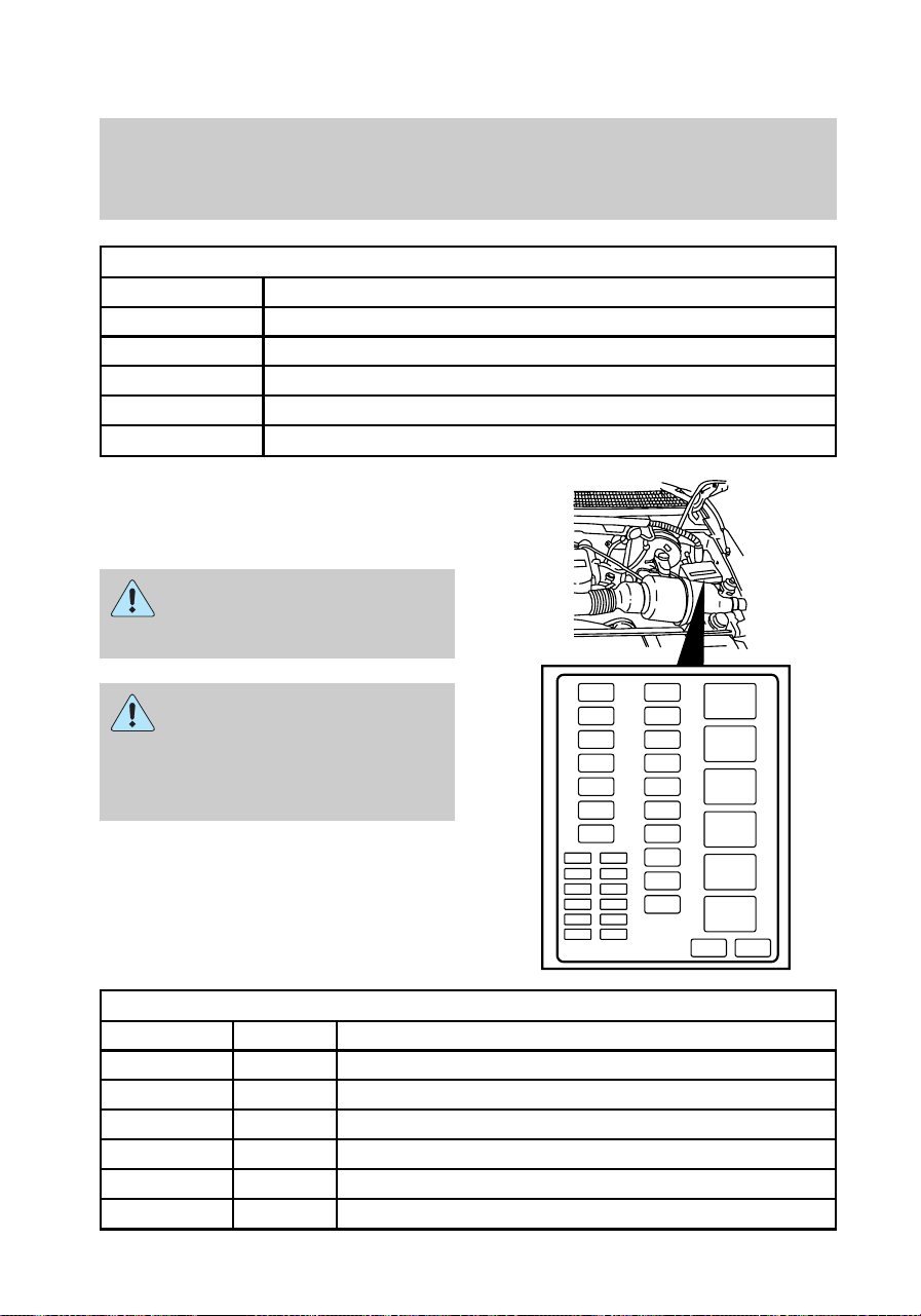
Relays
Position Description
1 Interior lamps relay
2 Battery saver relay
3 Not used
4 One touch down relay
5 Accessory delay relay
Power distribution box
Lift cover towards left of vehicle to
access the power distribution box.
Always disconnect the
battery before servicing
high current fuses.
Always replace the cover
to the Power Distribution
Box before reconnecting the
battery or refilling fluid
reservoirs.
Fuses
Position Amps Description
1 20 Trailer tow back-up and tail lamps
2 10 Air bag diagnostic monitor
3 15 Power locks
4 15 Air suspension
5 20 Horn
6 15 Audio system
29
6
5
4
3
2
1
28
27
26
25
24
23
19
18
17
16
15
14
13
22
21
20
12
11
9
7
5
3
1
12
10
8
6
4
2
f12_eng_comp_fuses
Roadside emergencies
139

Fuses
Position Amps Description
7 15 Parking and tail lamps
8 30 Headlamps
9 15 Daytime running lamps and fog lamps
10 25 Auxiliary power point
11 - Not used
12 - Not used
13 - Not used
14 60/20 4WABS/rear anti-lock brake
15 50 Air suspension compressor
16 40 Trailer tow battery charge and stop/turn lamps
17 30 4WD transfer case shift motor and clutch
18 30 Driver power seat
19 20 Fuel pump
20 50 Instrument panel fuse panel ignition switch feed
21 50 Instrument panel fuse panel ignition switch feed
22 50 I/P fuse panel battery feed
23 40 I/P blower
24 30 PCM power
25 30 Power windows
26 - Not used
27 - Not used
28 30 Trailer tow electronic brake
29 - Not used
Diodes
Position Description
1 Rear ABS diode
2 PCM diode
Roadside emergencies
140
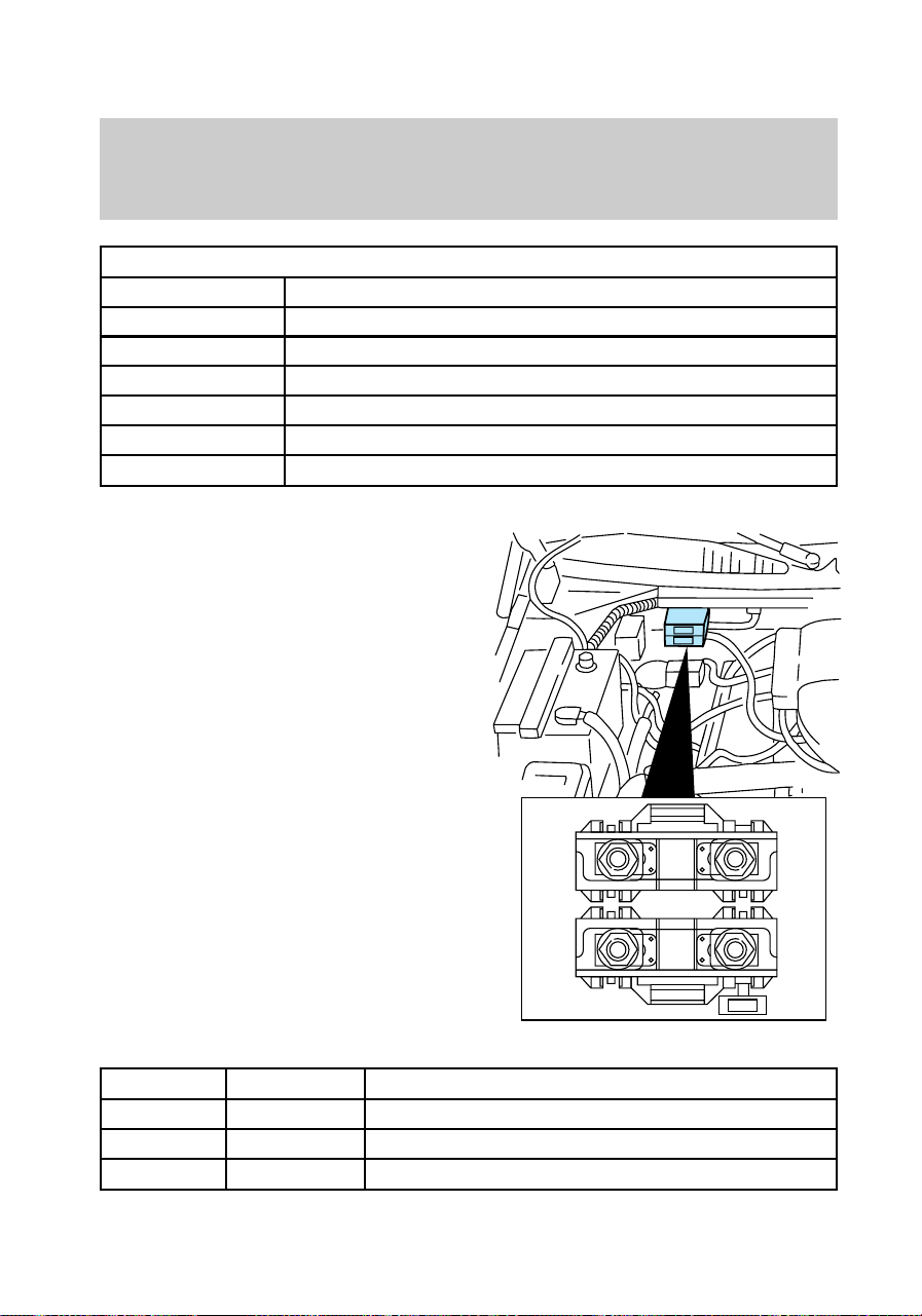
Relays
Position Description
1 Windshield wipers HI/LO speed
2 Windshield wipers run/park relay
3 Washer pump relay
4 Fuel pump relay
5 Horn relay
6 PCM power relay
Primary battery fuses
(megafuses)
Primary battery fuses are located
under the PRIMARY BATTERY
FUSE cover next to starter relay.
Ford recommends that megafuses
only be serviced by a qualified
service technician.
Location Amperage Description
1 175 Power network box megafuse
2 175 Alternator megafuse
3 20 Alternator field minifuse
1
2
3
f12_megafuse
Roadside emergencies
141
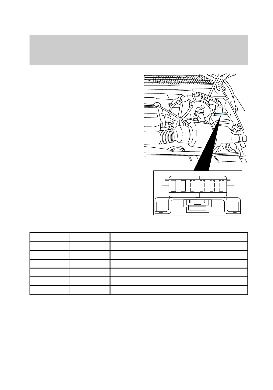
Engine minifuse panel
The minifuse panel is located
behind the power distribution box.
Location Amperage Description
1 5 Powertrain control module (PCM)
2 20 Trailer tow stop/turn lamps
3 - Not used
4 - Not used
5 - Not used
6 - Not used
CHANGING FLAT TIRES
If you get a flat tire while driving,
do not apply the brakes heavily.
Instead, gradually reduce the
speed while holding the steering
wheel firmly. Move the vehicle to a
safe spot off to the side of the
road.
1 2 3 4 5 6
f12_minifuses
f12_flat_tires
f12_change_proc
Roadside emergencies
142
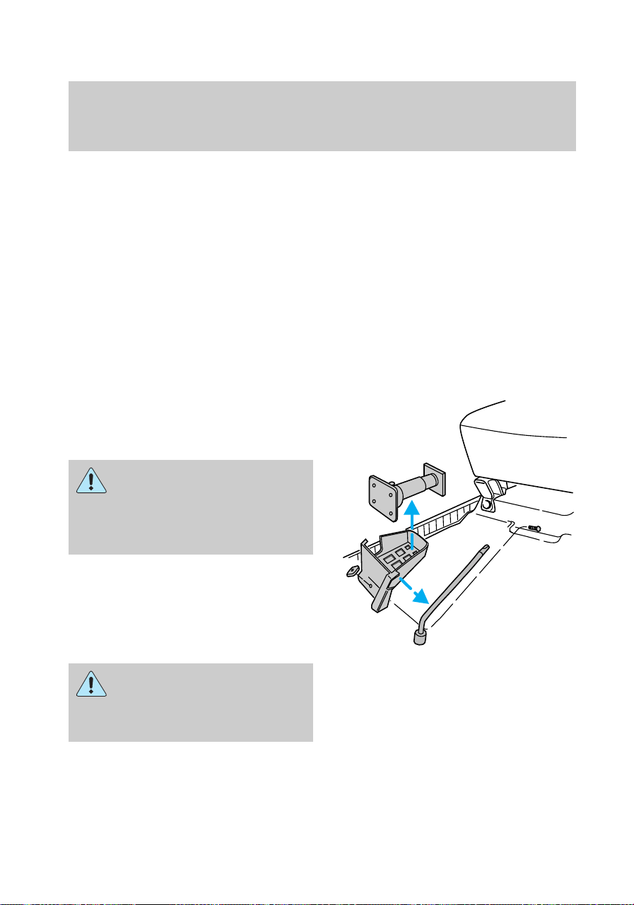
Tire change procedure
1. Park on a level surface.
2. Activate the hazard flashers.
3. Set the parking brake.
4. Place the gearshift in P (Park)
(automatic transmission) or R
(Reverse) (manual transmission).
For 4WD vehicles equipped with
Lever-operated transfer case, make
sure that the lever is not in the N
(Neutral) position.
5. Block the diagonally opposite
wheel.
6. Remove the jack and lug wrench
from under the passenger seat.
On vehicles equipped with
Air Suspension, turn OFF
the Air Suspension switch prior
to jacking, hoisting or towing
your vehicle.
To avoid injury, never run
the engine with one wheel
off the ground, such as when
changing a tire.
f12_removing_spare
Roadside emergencies
143
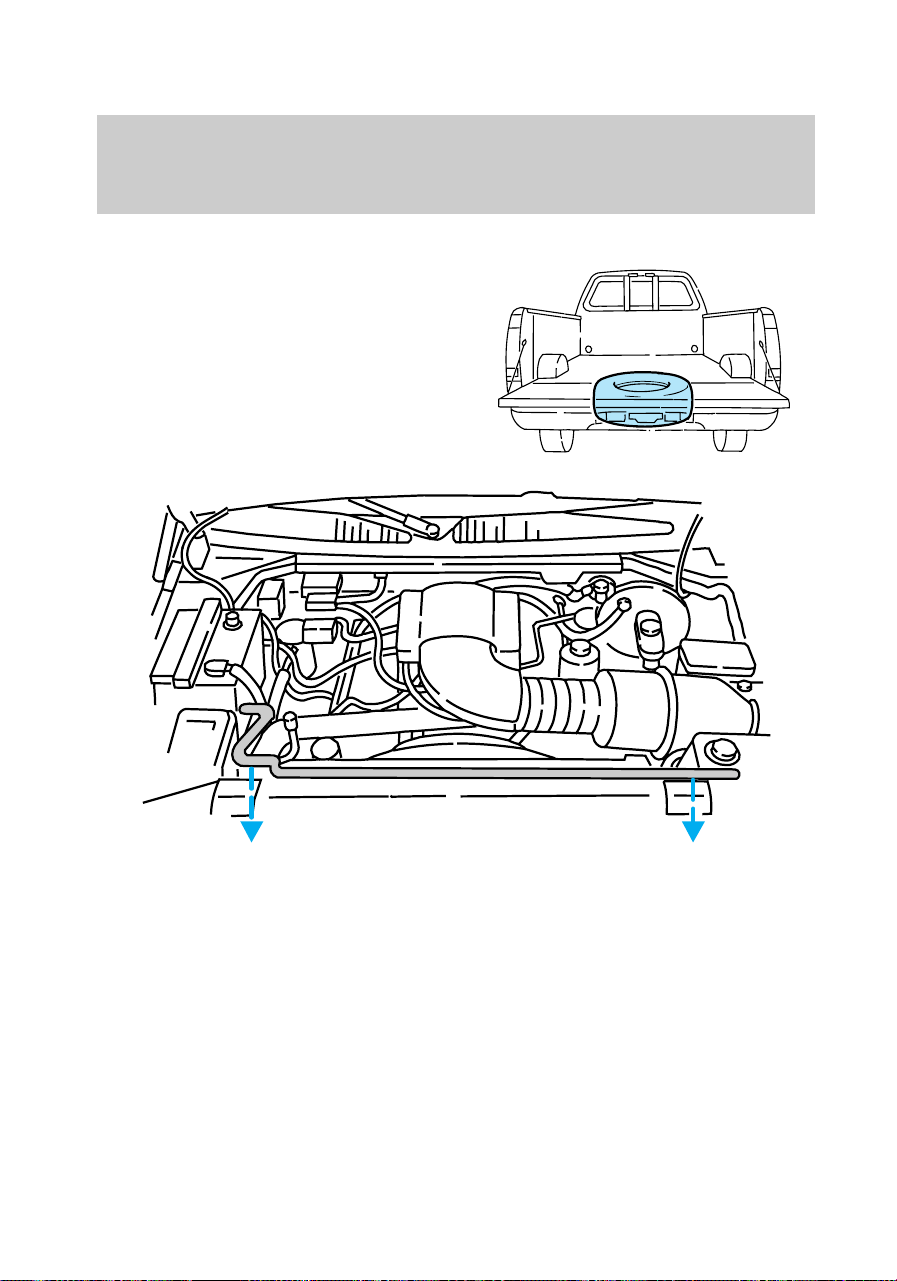
Removing spare from storage
Your vehicle is equipped with a
full-size spare tire. To remove the
spare tire:
1. Carefully remove the jack
handle from the retaining clips
(above radiator in engine
compartment).
Roadside emergencies
144
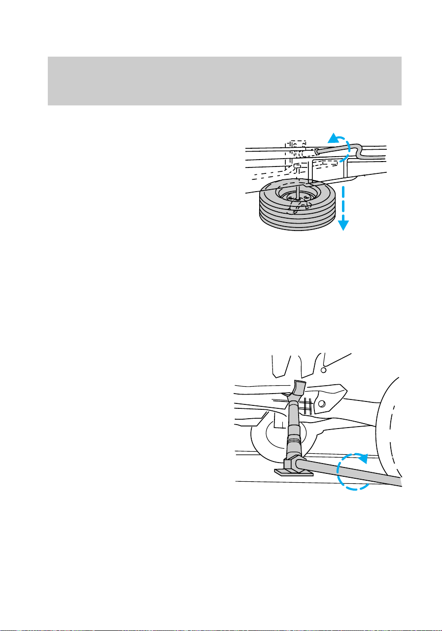
2. To lower the spare tire, insert
the jack handle into the rear
bumper opening and turn it
counterclockwise.
Removing flat tire and installing
spare
1. Use the tip of the lug wrench to
remove the wheel ornament. Insert
the lug wrench tip into the notch
in the wheel ornament.
2. Loosen the wheel nuts with the
lug wrench. Do not remove the lug
nuts yet.
3. Position the jack as shown for
your specific vehicle (4WD or
2WD). Use the thumbwheel to
raise the jack to the desired
height.
• Front (2WD)
f12_removing_flat
Roadside emergencies
145
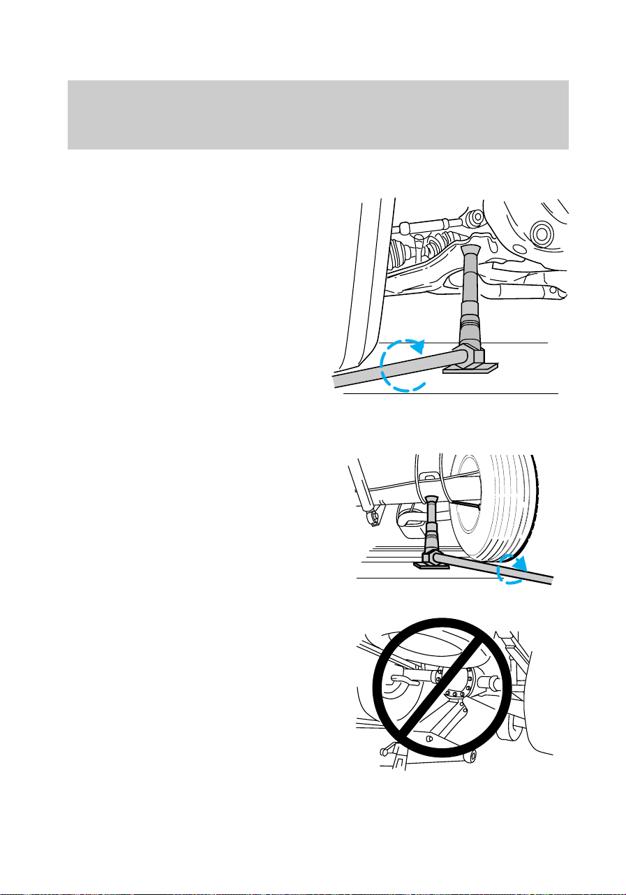
• Front (4WD)
• Rear
Never use the differential as a
jacking point.
Roadside emergencies
146
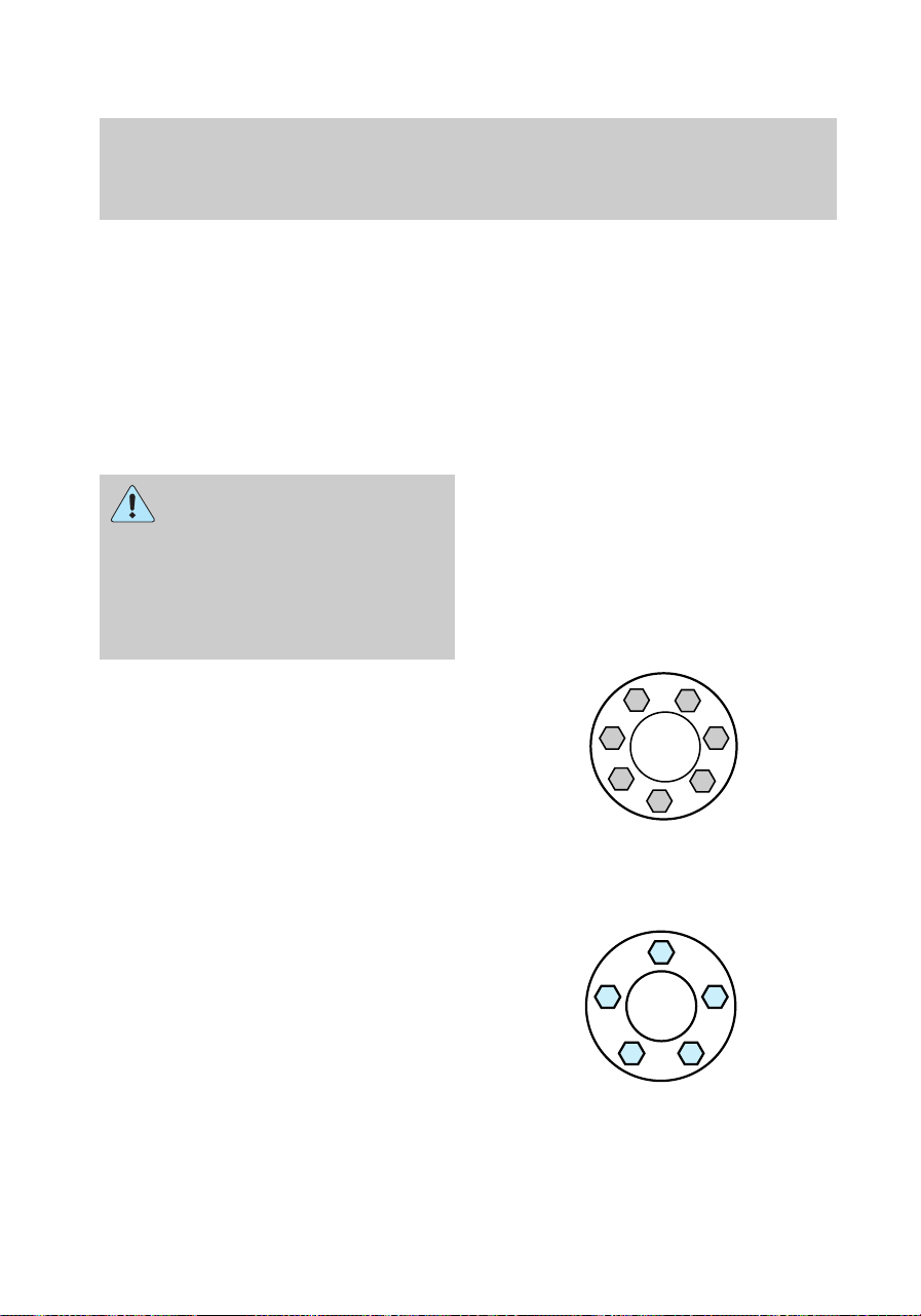
4. Raise the vehicle high enough
for the spare tire to clear the
ground when installed.
5. Remove the wheel lug nuts.
6. Remove the flat tire and install
the spare.
7. Install the lug nuts and tighten
until the wheel is seated.
Installing wheels without a
good metal-to-metal
contact at the wheel mounting
surface can cause the wheel lug
nuts to loosen and could allow
the wheel to come off while the
vehicle is in motion.
If your vehicle is equipped with
seven-lug hubs, use the following
tightening pattern:
If your vehicle is equipped with
five-lug hubs, use the following
tightening pattern:
8. Position the wheel ornament on
the wheel nuts and secure to the
wheel.
16
34
7
5
2
1
4
2
5
3
Roadside emergencies
147

9. To stow the flat tire, lay the tire
on the ground with the inboard
side facing up. Install the retainer
through the wheel center and slide
the wheel under the vehicle. Turn
the spare handle clockwise until
the tire is raised to its original
position underneath the vehicle.
The spare handle ratchets when
the tire is raised to the stowed
position. It will not allow you to
overtighten.
10. Unblock the wheel.
11. Stow the jacking equipment
under the passenger seat and stow
the jack handle in the engine
compartment.
12. As soon as possible, tighten the
wheel nuts with a torque wrench
to 115–165 Nm (85–115 lb-ft).
JUMP STARTING YOUR
VEHICLE
The gases around the
battery can explode if
exposed to flames, sparks, or lit
cigarettes. An explosion could
result in injury or vehicle
damage.
Do not push-start your
vehicle. You could damage
the catalytic converter. For
further information, see Jumper
Cables in the Index.
com_jump-starting.01
Roadside emergencies
148
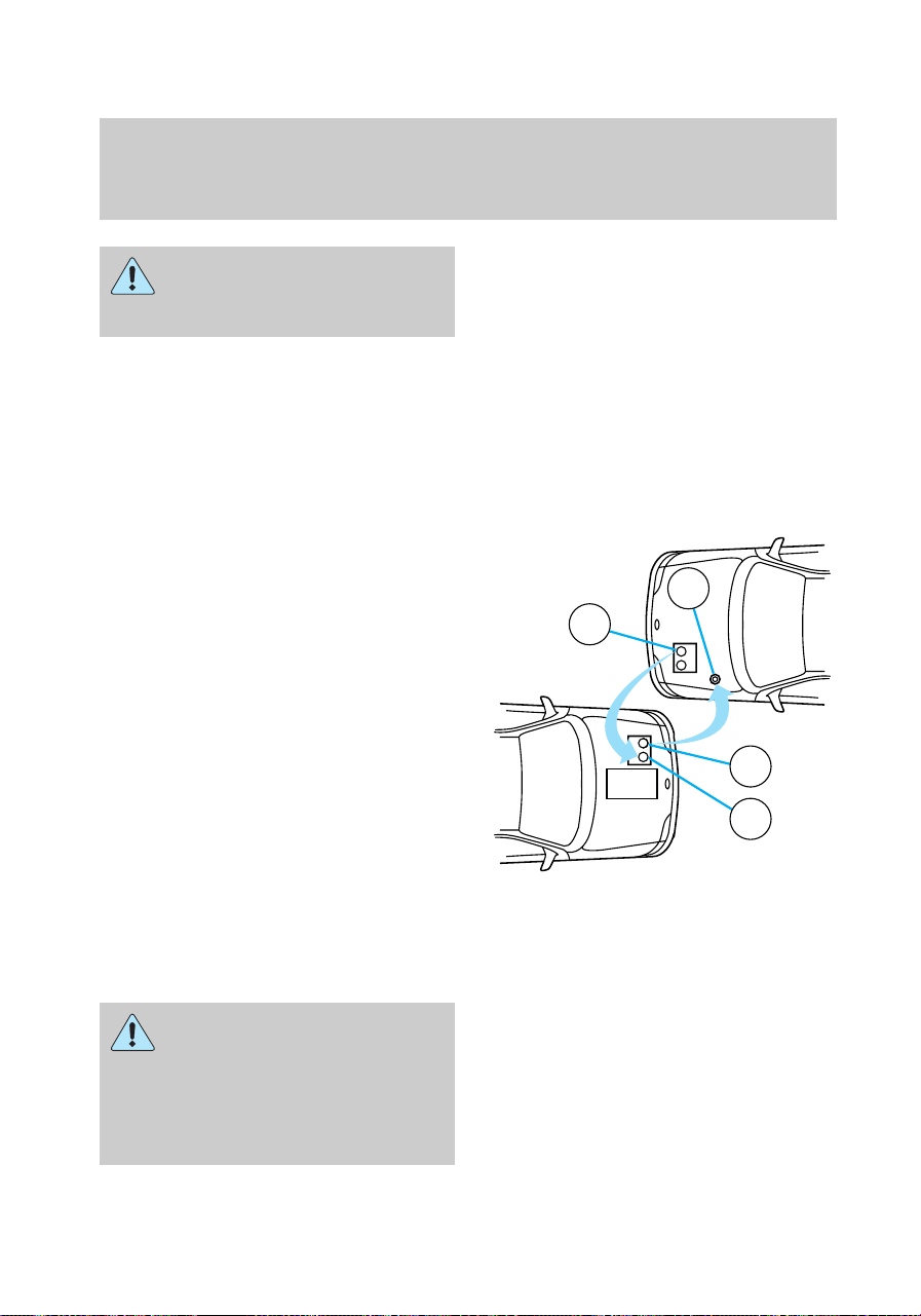
Batteries contain sulfuric
acid which burns skin,
eyes, and clothing.
CONNECTING THE JUMPER
CABLES
1. Position the vehicles so that
they do not touch one another.
2. Switch off the engine. Switch off
any unnecessary electrical
equipment.
3. Connect the positive (+)
terminal of the discharged battery
(1) to the positive (+) terminal of
the booster battery (2).
4. Connect one end of the second
lead to the negative (-) terminal of
the booster battery (3) and the
other end to a metal part of the
engine to be started (4), not to the
negative (-) terminal of the
discharged battery.
5. Make sure that the jump leads
are clear of moving parts of the
engine.
Do not connect the end of
the second cable to the
negative ([-]) terminal of the
battery to be jumped. A spark
may cause an explosion of the
gases that surround the battery.
+
–
+
–
3
2
1
4
com_connecting_cables.01
com_jump_starting.01
Roadside emergencies
149
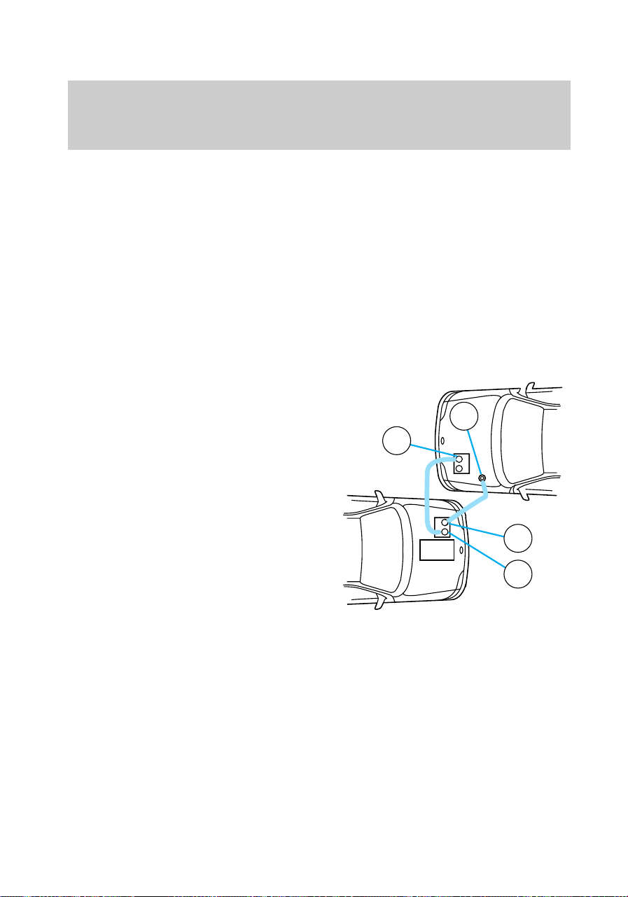
JUMP STARTING
1. Start the booster vehicle and
run the engine at moderately
increased speed.
2. Start the engine of the vehicle
with the discharged battery.
3. Once the engine has been
started, run both vehicles for a
further three minutes before
disconnecting the leads.
REMOVING THE JUMPER
CABLES
1. Remove the jumper cables in
reverse order. Take the cable off
the metallic surface (1) first,
followed by the cable on the
negative (-) booster battery
terminal (2).
2. Remove the cable from the
positive (+) terminal of the booster
battery (3) and then the
discharged battery (4).
3. After the disabled vehicle has
been started, allow it to idle for a
while so the engine can “relearn”
its idle conditions.
WRECKER TOWING
It is recommended that your
vehicle be towed with wheel lift
and dollies or flatbed equipment.
Do not tow with slingbelt
equipment. Ford Motor Company
has not developed or approved a
T-hook or slingbelt towing
procedure.
+
–
+
–
2
3
4
1
com_removing_cables.01
f12_wrecker
Roadside emergencies
150
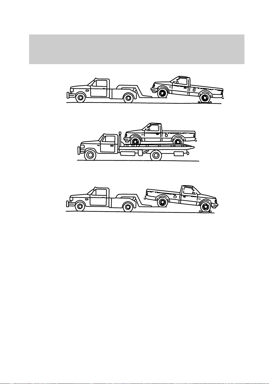
Ford recommends using one of the
above methods for towing.
Recreational towing (all wheels
on the ground)
Follow these guidelines for your
specific powertrain combination to
tow your vehicle with all four
wheels on the ground (such as
behind a recreational vehicle).
These guidelines are designed to
ensure that your transmission is
not damaged due to insufficient
lubrication.
2WD (manual and automatic
transmissions)
1. Place transmission in N
(Neutral).
f12_recreational_towing
Roadside emergencies
151

2. Maximum speed is 56 km/h (35
mph).
3. Maximum distance is 80 km (50
miles).
If a distance of 80 km (50 miles)
or a speed of 56 km/h (35 mph)
must be exceeded, you must
disconnect the rear driveshaft.
With the rear driveshaft
disconnected, the maximum speed
is 88 km/h (55 mph) and there are
no mileage restrictions.
See your dealer for help with
disconnecting the driveshaft.
4WD – Lever operated transfer
case (manual and automatic
transmissions)
1. Place transmission in P (Park).
2. Shift the transfer case to N
(Neutral).
3. Lockout the center disconnect
by capping off one of the front
axle vacuum motor lines. See your
Ford dealer for assistance.
4. Vehicle speed should not exceed
88 km/h (55 mph) and there are
no mileage restrictions.
4WD – Electronic shift transfer
case
1. Place transmission in N
(Neutral).
2. Shift the transfer case to 2H
(2WD high).
3. Lockout the center disconnect
by capping off one of the front
axle vacuum motor lines. See your
dealer for assistance.
Roadside emergencies
152

4. Maximum speed is 56 km/h (35
mph).
5. Maximum distance is 80 km (50
miles).
If a distance of 80 km (50 miles)
or a speed of 56 km/h (35 mph)
must be exceeded, you must
disconnect the rear driveshaft.
With the rear driveshaft
disconnected, the maximum speed
is 88 km/h (55 mph) and there are
no mileage restrictions.
See your dealer for help with
disconnecting the driveshaft.
Roadside emergencies
153

SERVICING YOUR VEHICLE
Service recommendations
To help you service your vehicle:
• We highlight do-it-yourself items
in the engine compartment for
easy location.
• As possible, we design parts that
can be replaced without tools.
• We provide you with a “Service
Guide” which makes tracking
routine service for your vehicle
easy.
If your vehicle requires
professional service, your
dealership can provide necessary
parts and service. Check your
“Warranty Information Booklet” to
find out which parts and services
are covered.
Use only recommended fuels,
lubricants, fluids and service parts
conforming to specifications.
Motorcraft parts are designed and
built to provide the best
performance in your vehicle.
Precautions when servicing
your vehicle
Be especially careful when
inspecting or servicing your
vehicle. Here are some general
precautions for your safety:
• Do not work on a hot engine.
• If you must work with the
engine running, avoid wearing
loose clothing or jewelry that
com_service_recommendations.01
com_precautions_servicing.02
Maintenance and care
154

could get caught in moving
parts. Take precautions with
long hair.
• Do not work on a vehicle with
the engine running in an
enclosed space, unless you are
sure you have enough
ventilation.
• Keep all lit cigarettes, open
flames and other lit material
away from the battery and all
fuel related parts.
If you disconnect the battery, the
engine must “relearn” its idle
conditions before your vehicle will
drive properly, as explained in
Battery in this chapter.
Working with the engine off
• Automatic transmission
1. Set the parking brake fully and
ensure the gearshift is securely
latched in P (Park).
2. Turn off the engine and remove
the key.
3. Block the wheels to prevent the
vehicle from moving unexpectedly.
• Manual transmission
1. Set the parking brake, depress
the clutch and place the gearshift
in 1 (First).
2. Turn off the engine and remove
the key.
3. Block the wheels to prevent the
vehicle from moving unexpectedly.
Working with the engine on
• Automatic transmission
com_working_off.02
com_working_on.02
Maintenance and care
155

1. Set the parking brake fully and
ensure the gearshift is securely
latched in P (Park).
2. Block the wheels to prevent the
vehicle from moving unexpectedly.
Do not start your engine
with the air cleaner
removed and do not remove it
while the engine is running.
• Manual transmission
1. Set the parking brake, depress
the clutch and place the gearshift
in 1 (First).
2. Block the wheels to prevent the
vehicle from moving unexpectedly.
f12_opening_hood
Maintenance and care
156
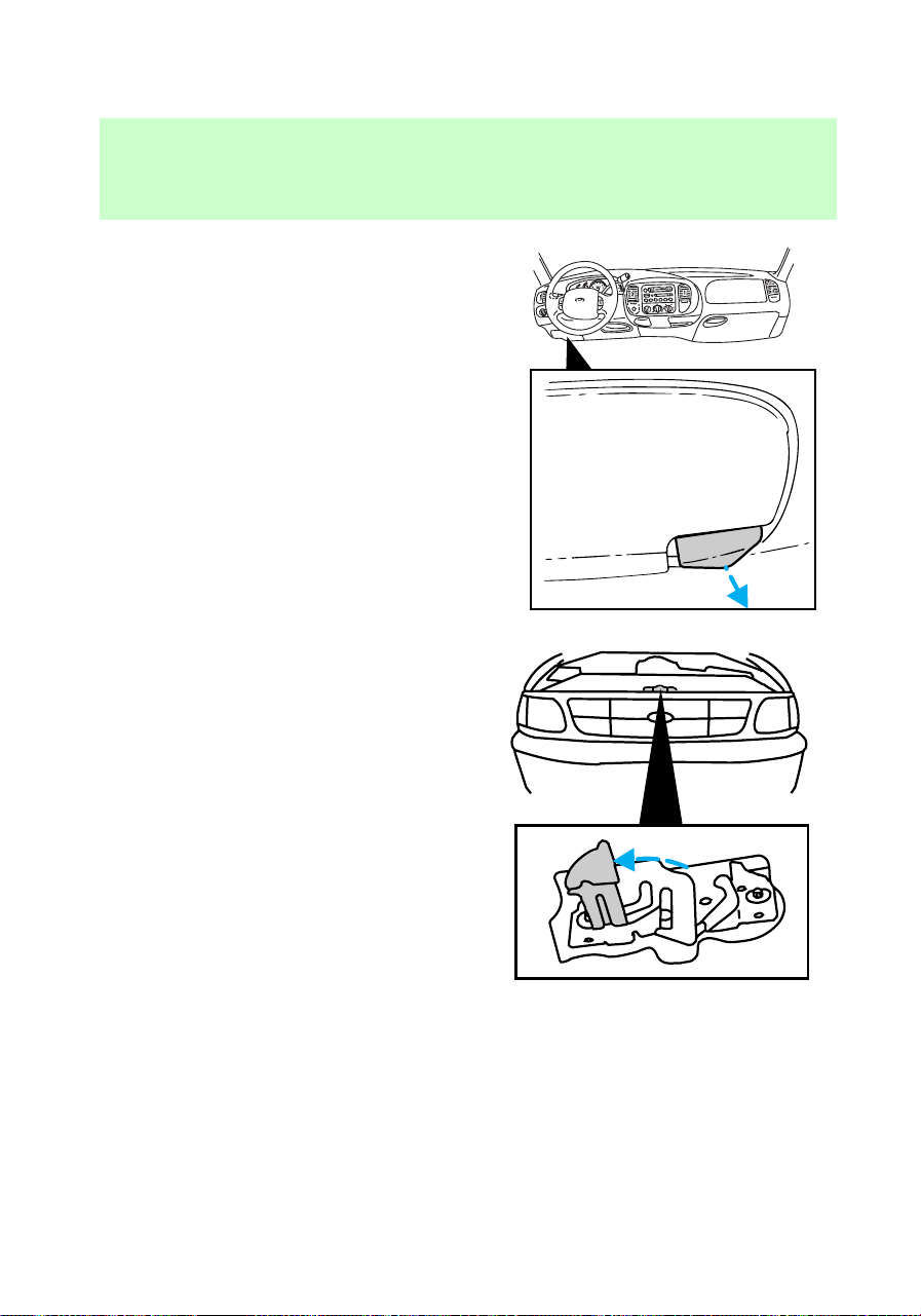
Opening the hood
1. Inside the vehicle, pull the hood
release handle located under the
bottom left corner of the
instrument panel.
2. While applying downward
pressure on the hood, push the
hood latch handle located just left
of the center of the hood.
3. Lift the hood.
After closing the hood, try to lift it
to be sure that it is closed
securely.
Lubricate the hood latch every six
months to ensure proper
operation.
HOOD
f12_4.2L_engine_components
Maintenance and care
157

4.2L engine
1. Battery
2. Engine oil filler
3. Engine oil dipstick
4. Clutch fluid reservoir (if
equipped)
5. Brake master cylinder
6. Power distribution box
7. Engine coolant recovery
reservoir
8. Radiator cap
9. Air cleaner
10. Power steering fluid reservoir
11. Automatic transmission fluid
dipstick (if equipped)
1
12 89 7 611 10
2
3
4
5
Maintenance and care
158
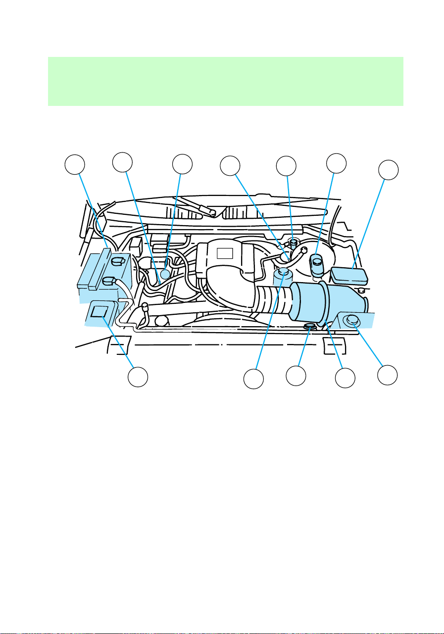
12. Windshield washer fluid
reservoir
4.6/5.4L engine
1. Battery
2. Automatic transmission dipstick
(if equipped)
3. Engine oil filler
4. Engine oil dipstick
5. Clutch fluid reservoir (if
equipped)
6. Brake master cylinder
7. Power distribution box
8. Engine coolant recovery
reservoir
9. Air cleaner
10. Radiator cap
10
11
8
12
9
1
2
4
5
6
7
3
f12_4.6L_5.4L_engine
Maintenance and care
159
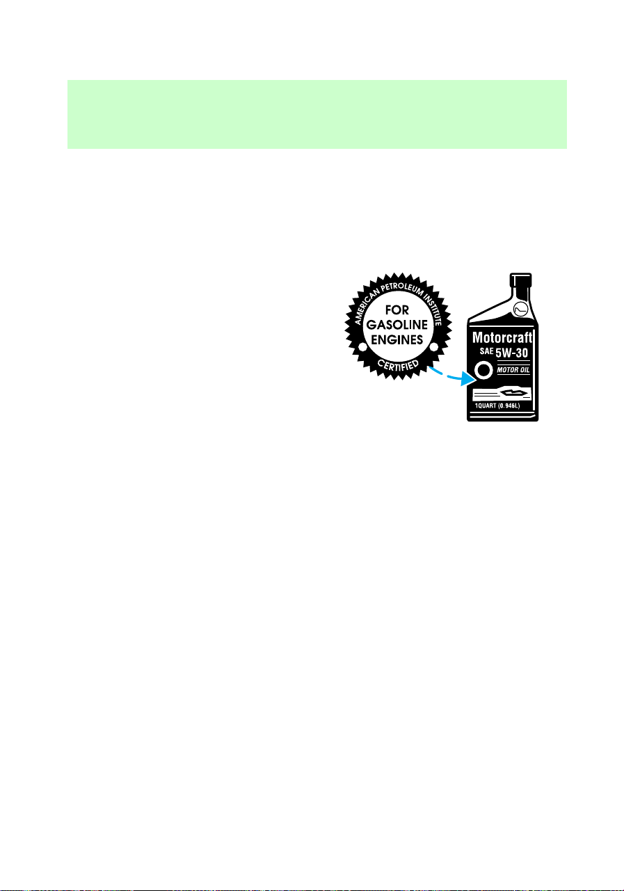
11. Power steering fluid reservoir
12. Windshield washer fluid
reservoir
ENGINE OIL
Oil specifications
Use WSS-M2C153–F motor oil
CERTIFIED FOR GASOLINE
ENGINES by the American
Petroleum Institute.
Engine oils with an SAE 5W-30
viscosity and displaying the
American Petroleum Institute
certification mark are preferred for
your vehicle. They provide the best
engine performance, fuel economy
and engine protection for all
climates down to –25°C (-15°F).
Do not use:
• “non-detergent” oils
• oils labeled API SA, SB, SC, SD,
SE, SF or SG
• additional engine oil additives,
oil treatments or engine
treatments
Additional engine oil additives, oil
treatments, or engine treatments
are never needed and could, under
certain conditions, lead to engine
damage which is not covered by
your Ford warranty.
Synthetic engine oils which are
CERTIFIED and of the preferred
viscosity may be used in your
engine. The engine oil and oil filter
must still be changed according to
the “Service Guide.”
f12_engine_oil
f12_oil_specs
Maintenance and care
160

Oil filters
Ford production and aftermarket
(Motorcraft) oil filters are designed
for added engine protection and
long life. If a replacement oil filter
is used that does not meet Ford
material and design specifications,
startup engine noises or knock
may be experienced. It is
recommended that you use the
appropriate Motorcraft oil filter (or
another brand meeting Ford
specifications) for your engine
application.
Checking engine oil
Check the engine oil each time you
fuel your vehicle.
Check the engine oil level more
frequently if the vehicle is carrying
a heavy load, towing a trailer,
idling for extended periods (like
police, taxi or shuttle service
vehicles) or driven at high speeds
for extended periods of time.
To check the oil:
1. Make sure the vehicle is on level
ground. If the engine is warm, turn
the engine off and wait a few
minutes for the oil to drain into
the oil pan.
2. Set the parking brake and
ensure the gearshift is latched in P
(Park) (automatic transmission) or
1 (First) (manual transmission).
3. Open the hood. Protect yourself
from engine heat.
4. Locate and carefully remove the
f12_checking_oil
Maintenance and care
161
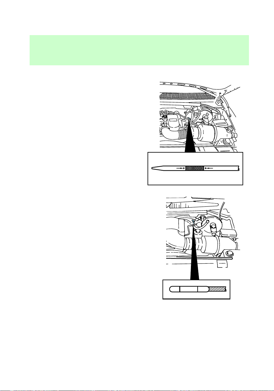
engine oil dipstick (4.2L and
4.6L/5.4L engines shown).
• 4.2L engine
• 4.6L/5.4L engine
5. Wipe the dipstick clean. Insert
the dipstick fully, then remove it
again. The oil level should be in
the range shown on the dipstick.
6. If the oil level is below the
minimum line, add engine oil as
necessary. If the oil level is below
the MIN line, add engine oil as
necessary. If the oil level is above
MAXMIN
MAXMIN
Maintenance and care
162
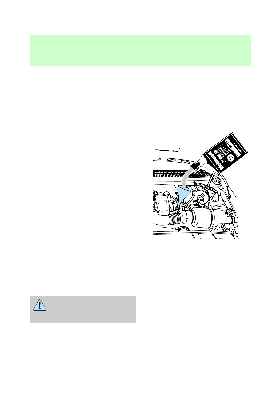
the MAX line, engine damage or
high oil consumption may occur
and some oil must be removed
from the engine by a service
technician.
7. Put the dipstick back in and
ensure it is fully seated.
Adding engine oil
1. Check the engine oil.
2. If the oil level is below the MIN
line, then add engine oil.
3. Remove the yellow oil filler cap.
4. Use a funnel to add oil through
the opening.
Make sure you use a certified
engine oil of the preferred
viscosity.
5. Recheck the oil level. Make sure
that the oil level is not above the
MAX line on the dipstick.
Continuous contact with
used motor oil has caused
cancer in laboratory mice.
f12_adding_oil
f12_brake_fluid
Maintenance and care
163
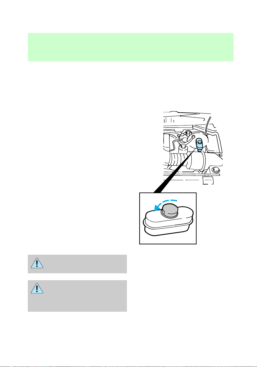
BRAKE FLUID
CHECKING AND ADDING
BRAKE FLUID
Brake fluid should be checked and
refilled as needed at least once
each year:
• Clean the reservoir cap before
removal to prevent dirt or water
from entering the reservoir.
• Visually inspect the fluid level.
• If necessary, add brake fluid
until the level reaches MAX. Do
not fill above this line.
• Use only a DOT 3 brake fluid
certified to meet Ford
specifications. Refer to
Lubricant specifications in the
Capacities and specifications
chapter.
Brake fluid is toxic.
If you use a brake fluid
that is not DOT 3, you will
cause permanent damage to your
brakes.
MAX
MIN
com_checking-adding_fluid.01
Maintenance and care
164
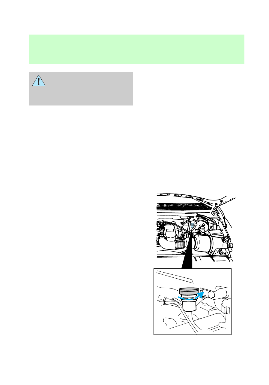
Do not let the reservoir for
the master cylinder run
dry. This may cause the brakes
to fail.
CHECKING AND ADDING
CLUTCH FLUID (IF EQUIPPED)
During normal operation, the fluid
level in the clutch reservoir will
slowly rise. If the fluid level drops,
maintain the fluid level at the step
in the reservoir.
Use only a DOT 3 brake fluid
designed to meet Ford
specifications. Refer to Capacities
and specifications.
1. Clean the reservoir cap before
removal to prevent dirt and water
from entering the reservoir.
2. Remove cap.
3. Add fluid until the level reaches
the FULL line.
f12_clutch_fluid
f12_washer_fluid
Maintenance and care
165
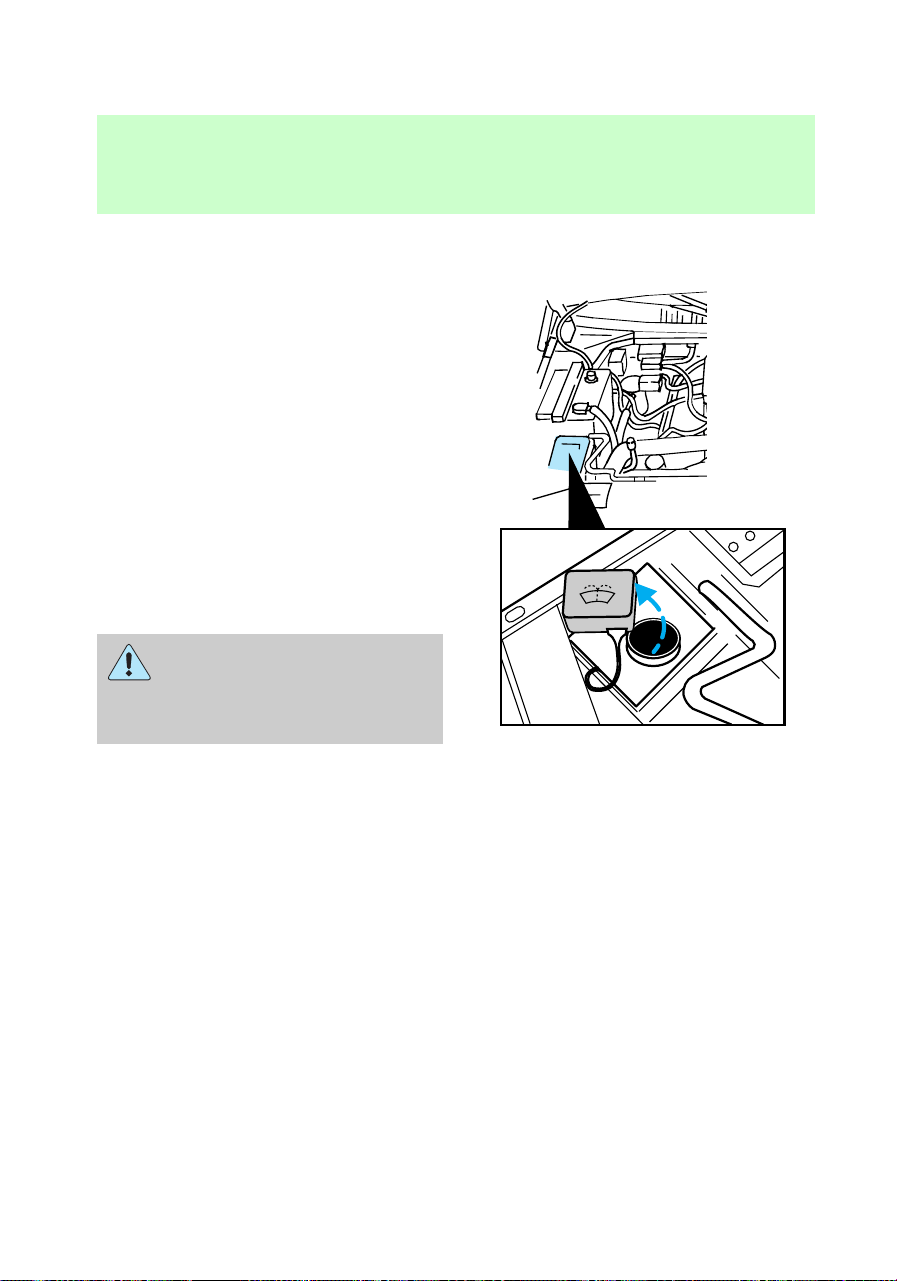
CHECKING AND ADDING
WINDSHIELD WASHER FLUID
1. Lift the washer fluid reservoir
cover.
2. Add washer fluid intil the level
reaches the FULL line.
Use only fluid that meets Ford
Specifications. Refer to Capacities
and specifications.
The addition of a bug shield to the
front of the vehicle may adversely
affect the washer system from
delivering fluid to the windshield.
Devices such as bug shields are
not recommended.
Windshield washer fluid
contains methanol and it is
poisonous. Follow all instructions
on the bottle of washer fluid.
What you should know about
washer fluid
In freezing weather [temperatures
below 0°C (32°F)], use washer
fluid containing a small amount of
antifreeze, such as methanol. State
or local regulations on volatile
organic compounds (VOCs) may
restrict the use of methanol, a
common type of antifreeze.
Use a non-methanol antifreeze in
freezing weather only if the fluid
does not damage the paint finish,
wiper blades and washer system.
WASHER FLUID
ONLY
f12_wysk_washer_fluid
f12_coolant
Maintenance and care
166
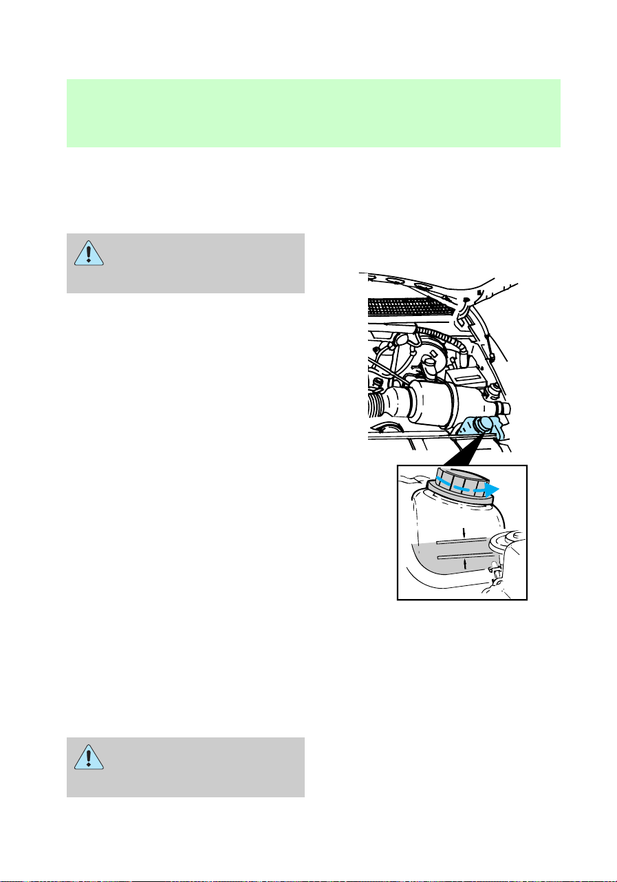
CHECKING AND ADDING
ENGINE COOLANT
Adding engine coolant
Do not put engine coolant
in the container for the
windshield washer fluid.
If sprayed on the windshield,
engine coolant could make it
difficult to see through the
windshield.
When the engine is cool, add a
50/50 mixture of engine coolant
and water to the engine coolant
recovery reservoir – DO NOT ADD
DIRECTLY TO THE RADIATOR.
Add straight water only in an
emergency, but you should replace
it with a 50/50 mixture of coolant
and distilled water as soon as
possible.
Check the coolant level in the
coolant recovery reservoir the next
few times you drive the vehicle. If
necessary, add enough of a 50/50
mixture of coolant and water to
bring the liquid level to the fill line
on the reservoir.
Never remove the coolant
recovery cap while the
engine is running or hot.
COOLANT FILL
LEVEL
f12_adding_coolant
Maintenance and care
167

If you must remove the coolant
recovery cap, follow these steps to
avoid personal injury:
1. Before you remove the cap, turn
the engine off and let it cool.
2. When the engine is cool, wrap a
thick cloth around the cap. Slowly
turn cap counterclockwise to the
first stop.
3. Step back while the pressure
releases.
4. When you are sure that all the
pressure has been released, use
the cloth to press the cap down,
turn it counterclockwise and
remove it.
Use Ford Premium Cooling System
Fluid E2FZ-19549–AA (in Canada,
Motorcraft CXC-8–B) or an
equivalent premium engine coolant
that meets Ford Specification
ESE-M97B44–A. Ford Premium
Engine Coolant is an optimized
formula that will protect all metals
and rubber elastomers used in
Ford cooling systems for 4 years or
80,000 km (50,000 miles).
Do not use alcohol or methanol
antifreeze or any engine coolants
mixed with alcohol or methanol
antifreeze. Do not use
supplemental coolant additives in
your vehicle. These additives may
harm your engine cooling system.
The use of an improper coolant
may void the warranty of your
vehicle’s engine cooling system.
f12_recycled_coolant
Maintenance and care
168

Recycled engine coolant
Ford Motor Company recommends
that Ford and Lincoln-Mercury
dealers use recycled engine
coolant produced by
Ford-approved processes. Not all
coolant recycling processes
produce coolant which meets Ford
specification ESE-M97B44–A, and
use of such coolant may harm
engine and cooling system
components.
Always dispose of used
automotive fluids in a responsible
manner. Follow your community’s
regulations and standards for
recycling and disposing of
automotive fluids.
Coolant refill capacity
To find out how much fluid your
vehicle’s cooling system can hold,
refer to Refill capacities in the
Capacities and specifications
chapter.
Have your dealer check the engine
cooling system for leaks if you
have to add more than a liter
(quart) of engine coolant per
month.
Severe winter climate
If you drive in extremely cold
climates [less than 36°C (34°F)], it
may be necessary to increase the
coolant concentration above 50%.
Refer to the chart on the coolant
container to ensure the coolant
concentration in your vehicle is
such that the coolant will not
f12_refill_capacity
f12_winter_climate
Maintenance and care
169
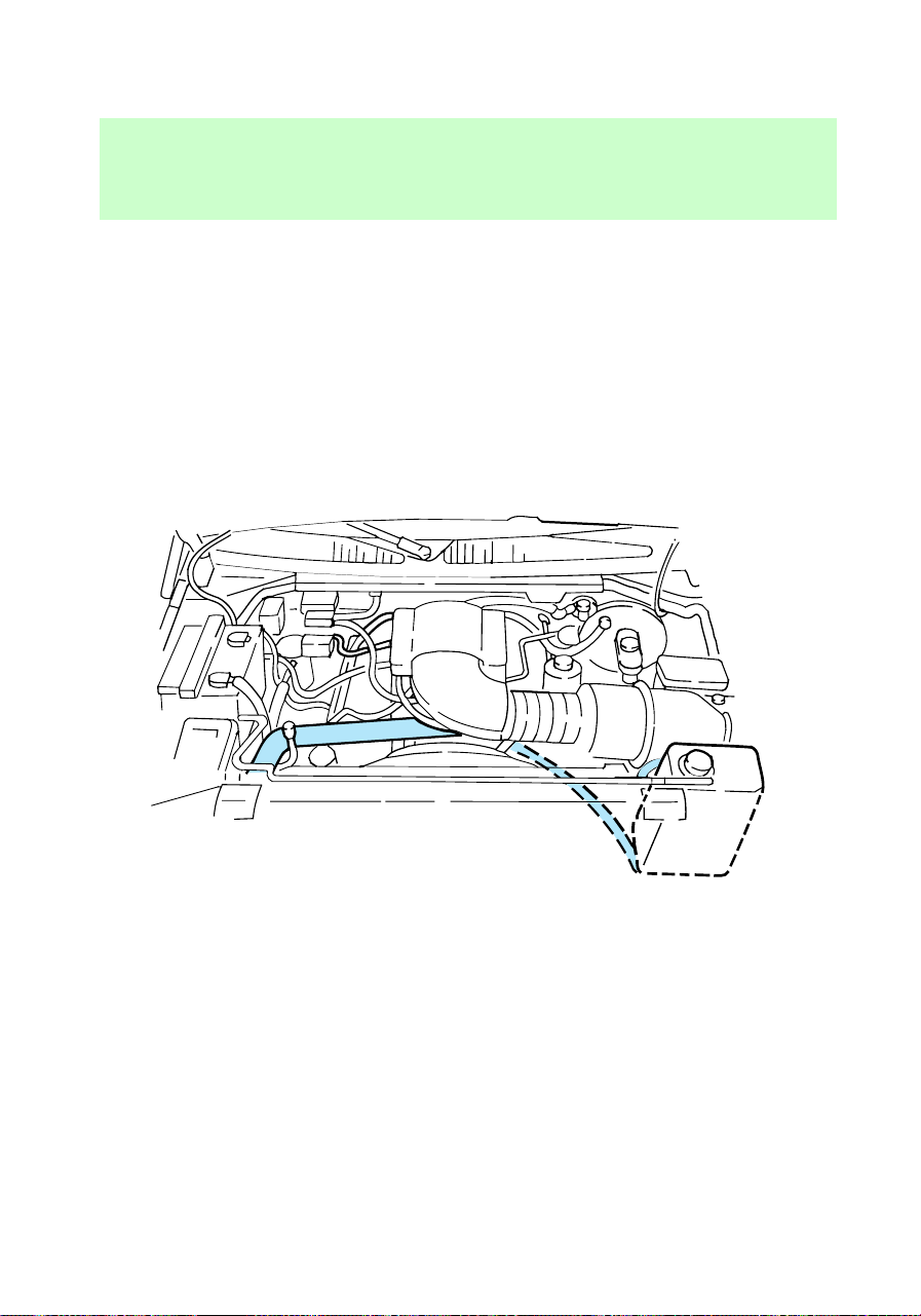
freeze at the temperature level in
which you drive during winter
months. Never increase the engine
coolant concentration above 60%.
Leave a 50/50 mixture of engine
coolant and water in your vehicle
year-round in non-extreme
climates.
Checking the cooling system
hoses
Inspect all engine and heater
system hoses and hose connections
for:
• deterioration
• leaks
• loose hose clamps
What you should know about
fail-safe cooling (if equipped)
Vehicles equipped with 4.6L or
5.4L engines have a fail-safe
com_checking_hoses.01
f12_wysk_failsafe_cooling
Maintenance and care
170
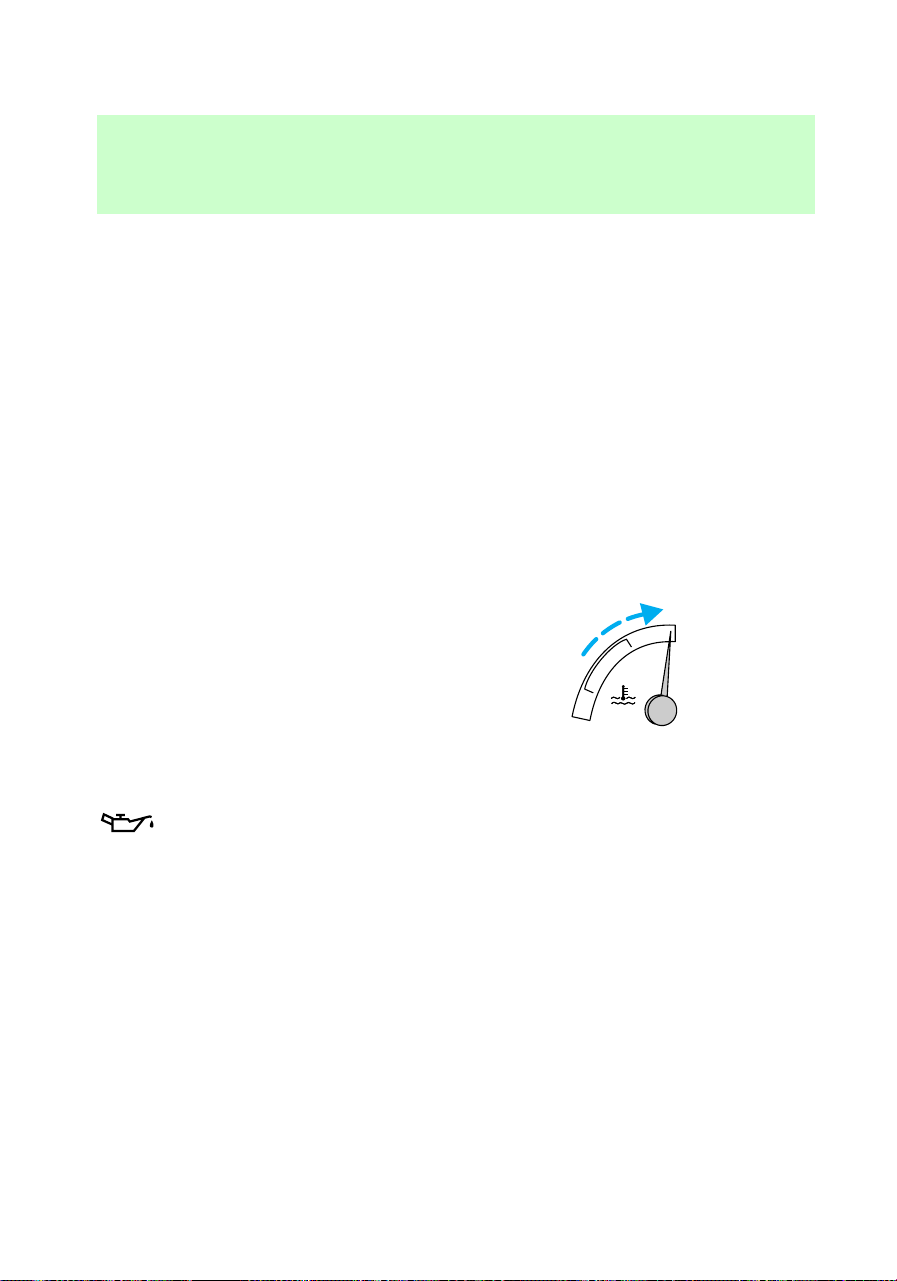
cooling mode. If the engine coolant
supply is depleted, this feature
allows the driver to drive the
vehicle (with limited power) for a
short distance in order to get the
vehicle to a service facility. Take
your vehicle to a service facility as
soon as possible to minimize
engine damage.
The actual distance your vehicle
can be driven depends on vehicle
load, road conditions and outside
temperature.
How fail-safe cooling works
If the engine overheats, the engine
will automatically switch from
eight to alternating four cylinder
operation. Each disabled cylinder
acts as an air pump and cools the
engine.
When this occurs, the engine
coolant temperature gauge will
move into the red area and the
light illuminates.
The
CHECK
ENGINE
light will illuminate,
indicating that vehicle service is
required.
The vehicle will still operate, but
will have limited engine power and
no air conditioning capability.
Continued operation will increase
engine temperature and cause the
engine to completely shut down.
The vehicle will coast to a stop.
As the engine temperature cools,
the engine may be re-started. Take
your vehicle to a service facility as
C
H
C
H
Maintenance and care
171
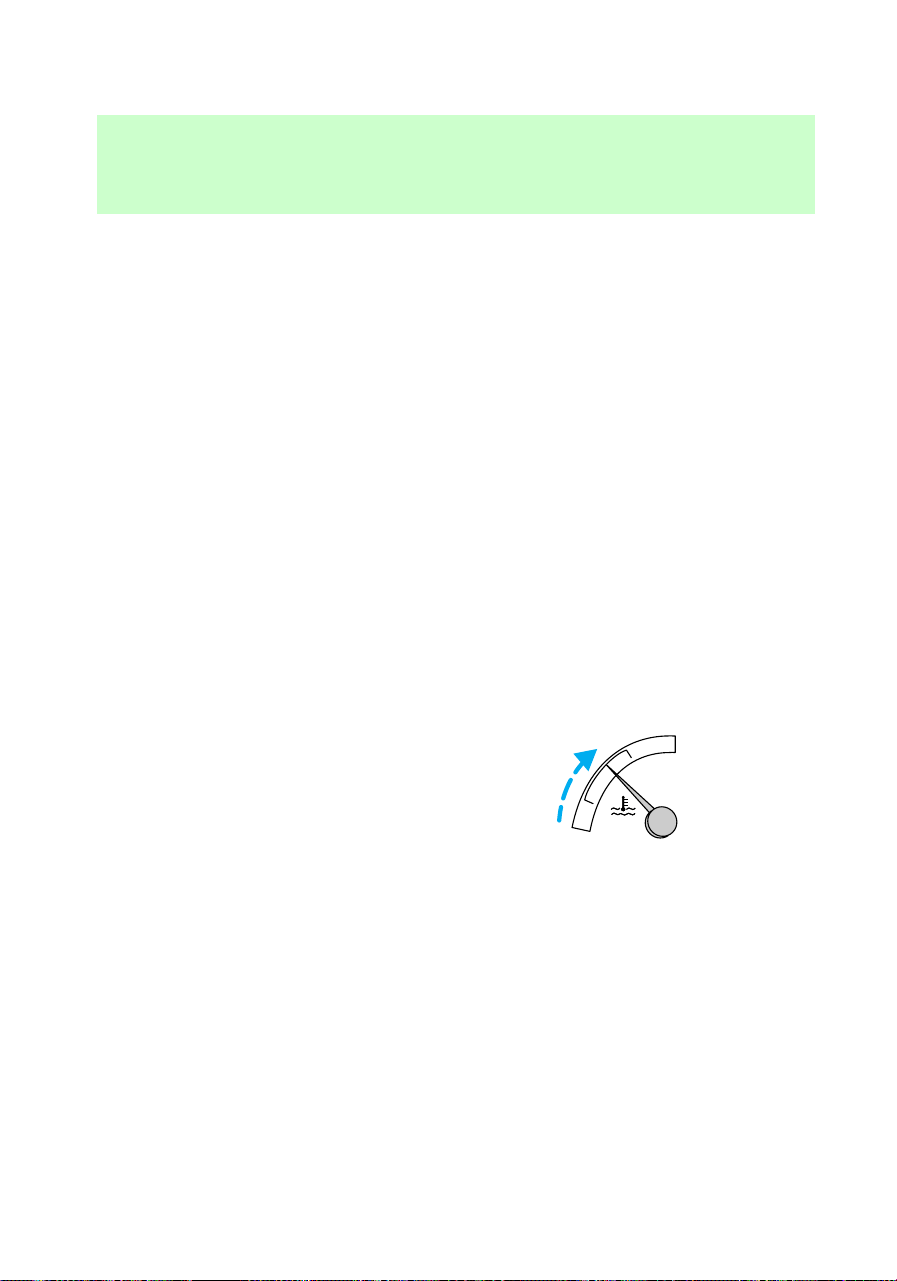
soon as possible to minimize
engine damage.
When fail-safe mode is
activated
• Pull off the road as soon as
possible.
• Immediately turn the engine off
to prevent severe engine
damage.
• Wait for the engine to cool.
• Check the coolant level.
CHECKING AND ADDING
POWER STEERING FLUID
Check the power steering fluid
level at least twice a year.
1. Start the engine.
C
H
C
H
f12_power_steering
Maintenance and care
172
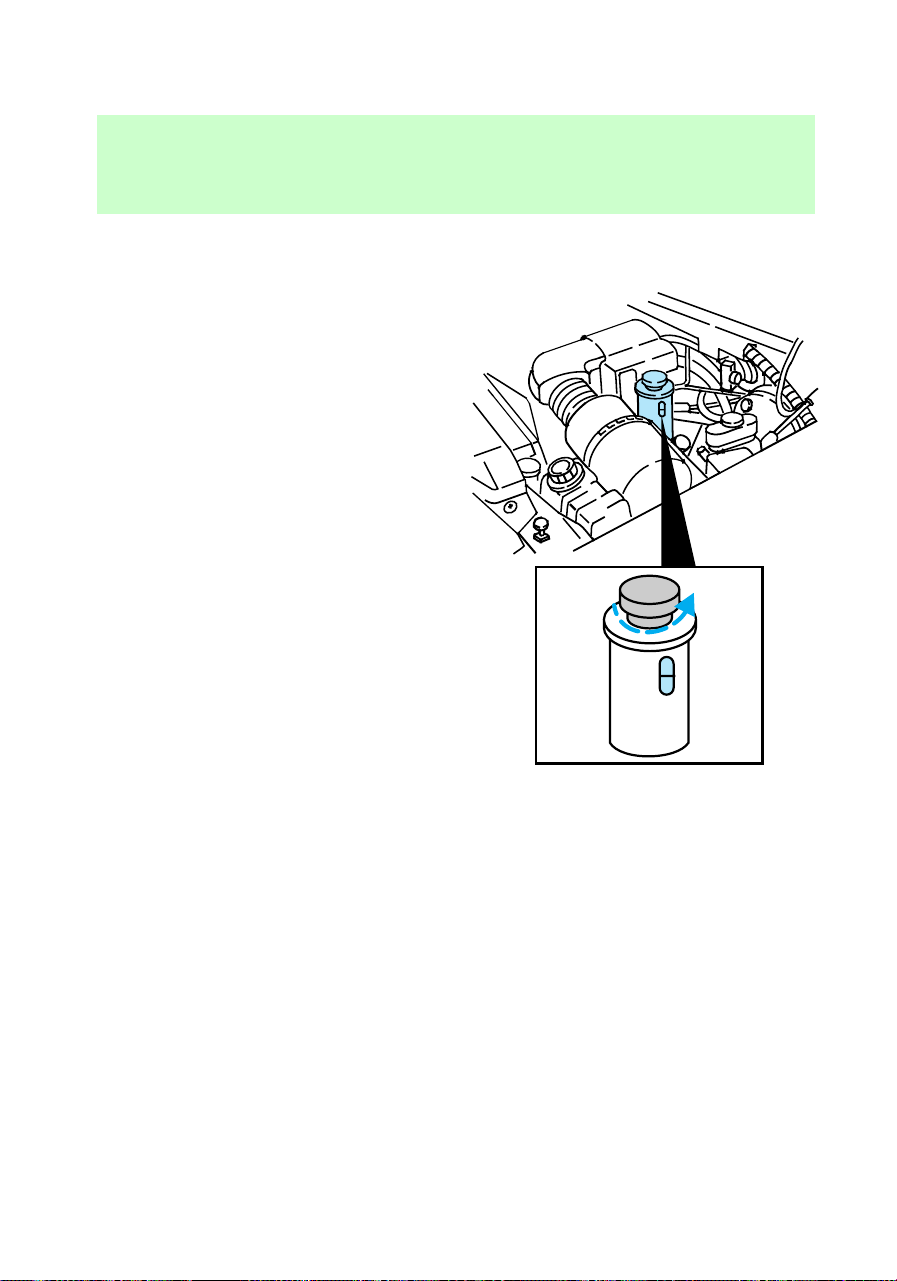
2. When the engine coolant
temperature gauge reaches the
normal zone, turn the engine off.
3. Visually inspect the fluid level in
the power steering fluid reservoir.
4. Add power steering fluid until
the fluid level reaches MAX.
Use only fluid that meets Ford
specifications. Refer to Capacities
and specifications.
CHECKING AND ADDING
TRANSMISSION FLUID
Checking and adding automatic
transmission fluid (if equipped)
Service the automatic transmission
according to the scheduled
intervals in the “Service Guide.”
MAX
MIN
MAX
MIN
f12_trans_fluid
f12_checking_adding_autotrans
Maintenance and care
173

Before adding any fluid, make sure
the correct type will be used. This
information is indicated on the
dipstick.
Do not drive the vehicle if the fluid
level is below the bottom hole on
the blade type dipstick (4R70W
transmission) or below the COLD
area on the bullet type dipstick
(E4OD transmission) and outside
temperatures are above 10°C
(50°F).
Your vehicle does not use up
transmission fluid. However, it is
recommended that you check the
transmission fluid at least twice a
year. The fluid level should be
checked if the transmission is not
working properly, i.e., if the
transmission slips or shifts slowly
or if you notice some sign of fluid
leakage.
It is preferable to check the
transmission fluid level at normal
operating temperature, after
approximately 32 km (20 miles) of
driving. However, you can check
the fluid level without driving to
obtain a normal operating
temperature if the outside
temperature is above 10°C (50°F).
If your vehicle has been operated
for an extended period at high
speeds, in city traffic during hot
weather or pulling a trailer, the
vehicle should be turned off for
about 30 minutes to allow the fluid
to cool before checking.
Maintenance and care
174
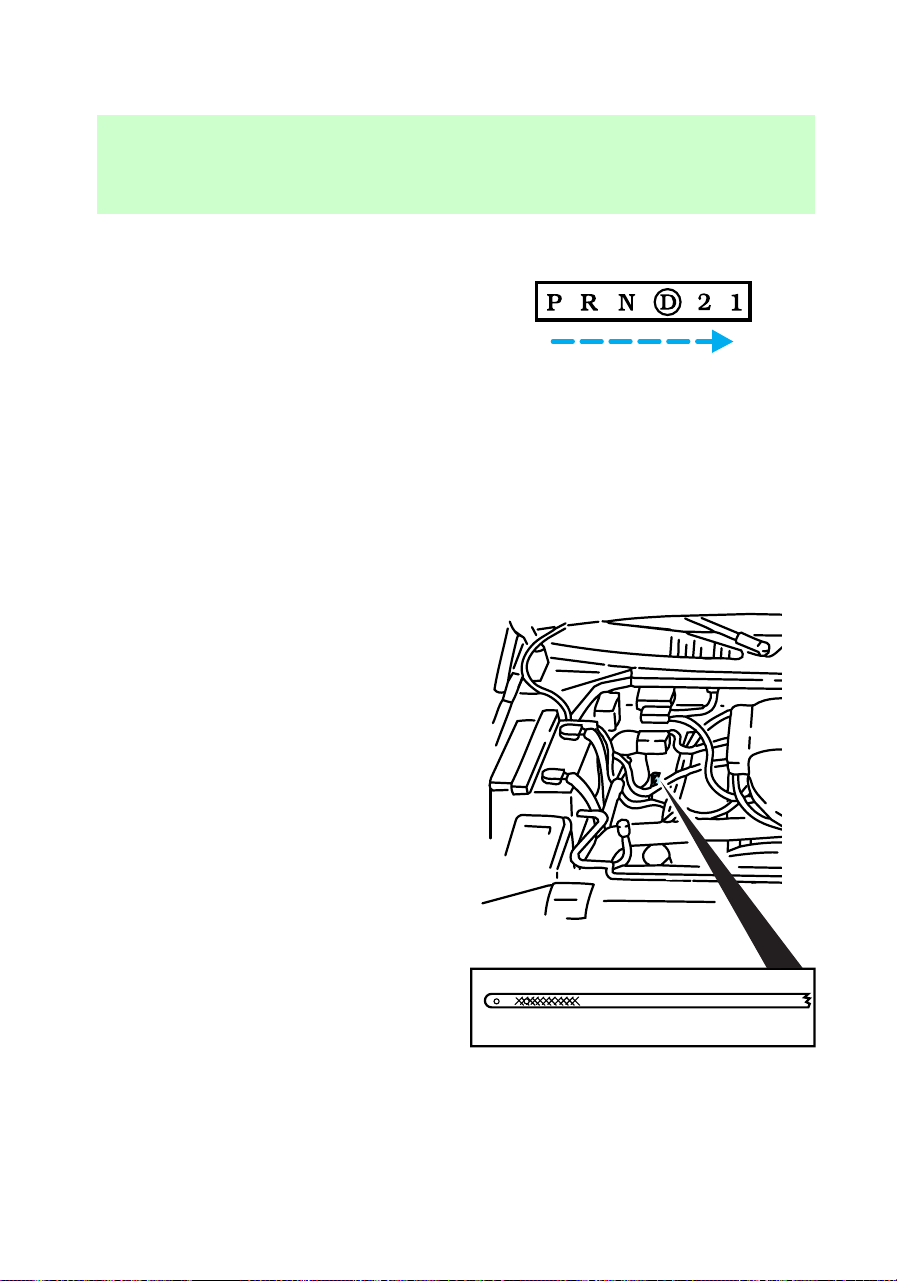
1. Park the vehicle on a level
surface.
2. Start the engine and move the
gearshift lever through all of the
gear ranges. Allow sufficient time
for each gear to engage.
3. Latch the gearshift lever in P
(Park), set the parking brake and
leave the engine running.
4. Remove the dipstick, wiping it
clean with a clean, dry rag.
5. Install the dipstick.
6. Remove the dipstick and inspect
the fluid level.
• For 4R70W transmissions, the
fluid level should be within the
crosshatched area, or if the
vehicle has not been driven,
DON'T ADD IF IN CROSSHATCHED AREA • CHECK WHEN HOT IDLING IN PARK
Maintenance and care
175
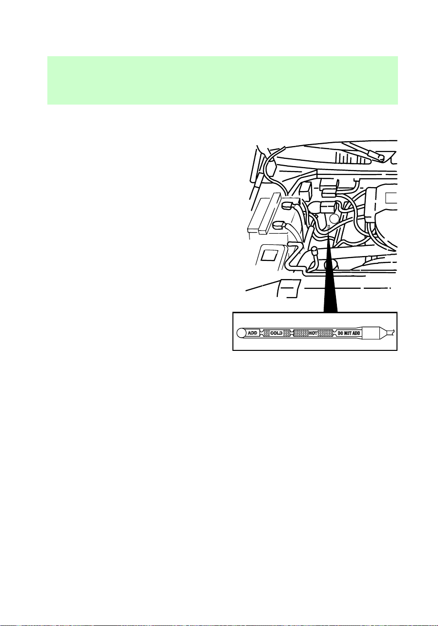
between the holes near the
bottom of the indicator.
• For E4OD transmissions, the
fluid level should be within the
HOT area, or if the vehicle has
not been driven, within the
COLD area.
7. If necessary, add fluid in .25L
(1/2 pint) increments through the
filler tube until the level is at the
correct area on the dipstick. If an
overfill occurs, excess fluid should
be removed by a qualified
technician.
f12_check_add_man_trans_fluid
Maintenance and care
176
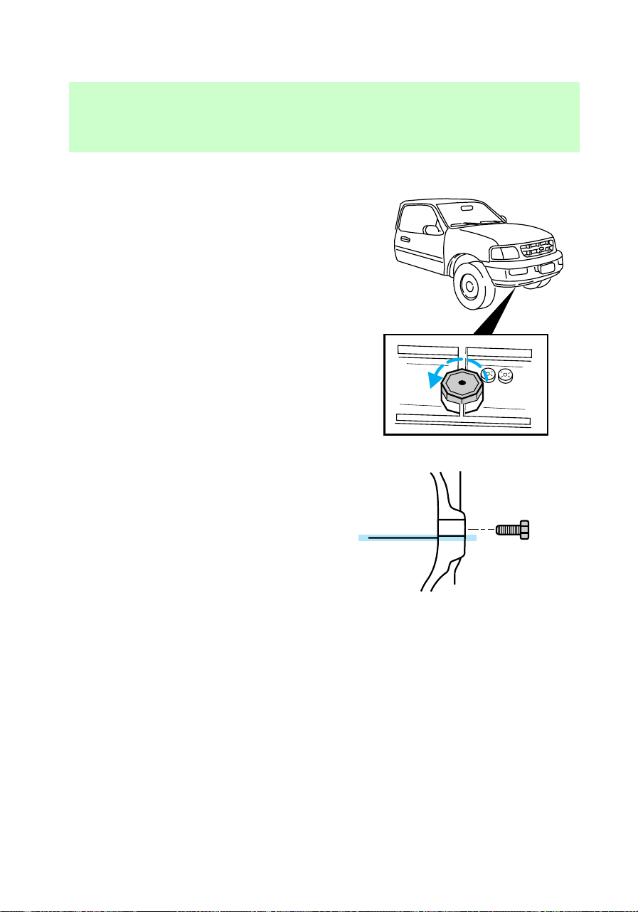
Checking and adding manual
transmission fluid (if equipped)
1. Clean the filler plug.
2. Remove the filler plug and
inspect the fluid level.
3. Fluid level should be at bottom
of the opening.
4. Add only enough fluid through
the filler opening so that the fluid
level is 6 mm (3/8 in) from the
bottom of the opening.
Use only fluid that meets Ford
specifications. Refer to the
Capacities and specifications
chapter.
f12_check_add_tcase_fluid
Maintenance and care
177
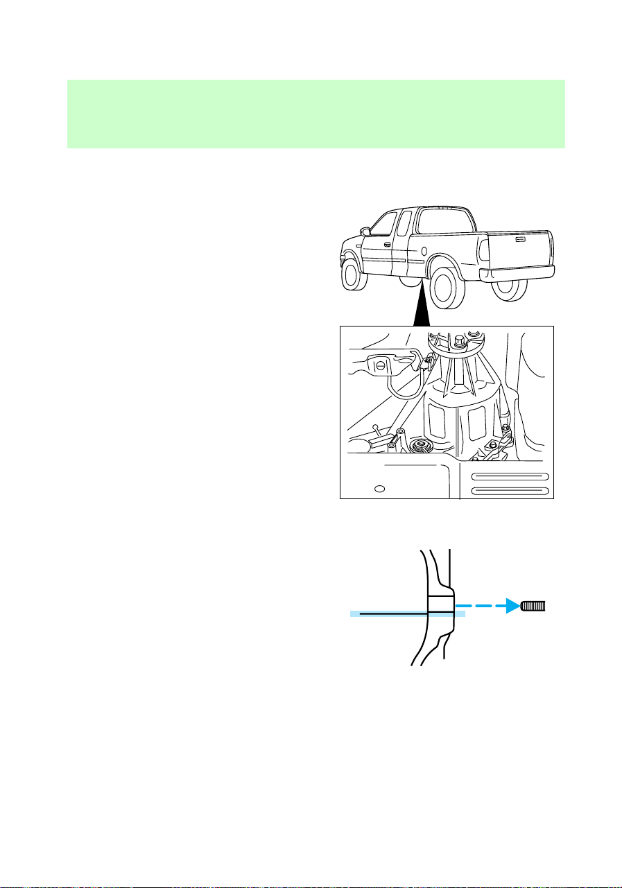
Checking and adding transfer
case fluid
1. Clean the filler plug.
2. Remove the filler plug and
inspect the fluid level.
3. Add only enough fluid through
the filler opening so that the fluid
level is at the bottom of the
opening.
Use only fluid that meets Ford
specifications. Refer to the
Capacities and specifications
chapter.
BATTERY
If the original equipment
maintenance-free battery needs
f12_battery
Maintenance and care
178
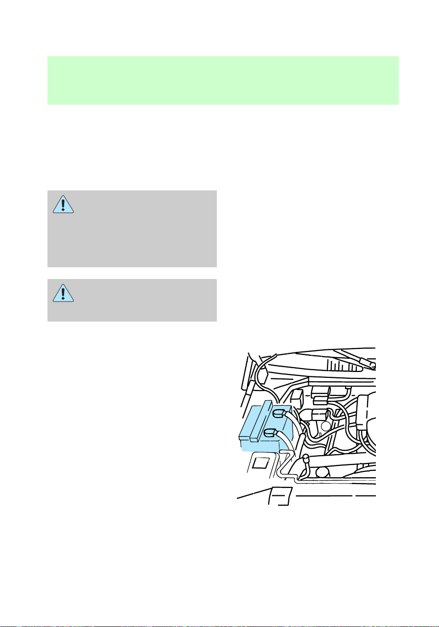
replacing, it may be replaced with
a low-maintenance battery. For
information on replacement
batteries, refer to Motorcraft part
numbers in the Capacities and
specifications chapter.
The gases around the
battery can explode if
exposed to flames, sparks, or lit
cigarettes. An explosion could
result in injury or vehicle
damage.
Batteries contain sulfuric
acid which burns skin,
eyes, and clothing.
Servicing your battery
A low-maintenance replacement
battery has removable vent caps
for checking the electrolyte level
and adding water. Check the
electrolyte level every 24 months
or 40,000 km (24,000 miles) in
average temperatures below 32°C
(90°F).
Keep the electrolyte level in each
cell up to the level indicator. Do
not overfill.
If the level gets low, refill the
battery with distilled water. If the
battery needs water quite often,
f12_servicing_battery
Maintenance and care
179

have the charging system checked
for a possible malfunction.
Your vehicle is equipped with a
battery saver feature designed to
prevent your battery from
accidental wear down due to doors
left ajar. For information on this
system, refer to the Controls and
features chapter.
Relearning idle conditions
Because your vehicle’s engine is
electronically controlled by a
computer, some control conditions
are maintained by power from the
battery. When the battery is
disconnected or a new battery is
installed, the computer must
“relearn” its idle conditions before
your vehicle will drive properly. To
complete this process:
1. Put the gearshift in P
(Park)(automatic transmission) or
N (Neutral)(manual transmission).
2. Turn off all accessories, and
start the engine.
3. Let the engine idle for at least
one minute.
4. The relearning process will
automatically complete as you
drive the vehicle.
• If you do not allow the engine to
relearn its idle, the idle quality
of your vehicle may be adversely
affected until the idle is
eventually relearned.
• If the battery has been
disconnected or a new battery
has been installed, the clock and
Maintenance and care
180
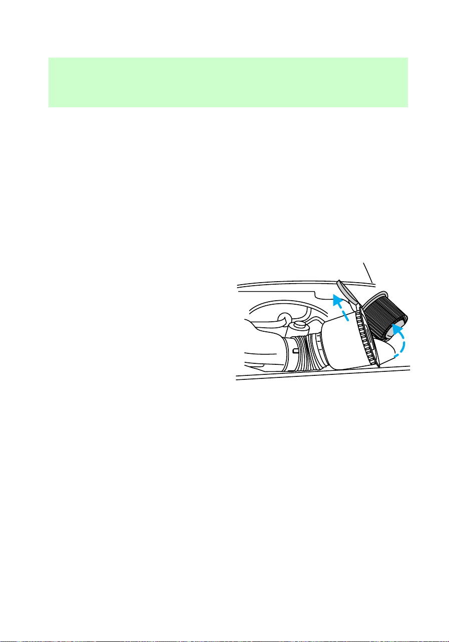
preset radio stations must be
reset once the battery is
reconnected.
• Always dispose of used
automotive batteries in a
responsible manner. Follow your
community’s standards for
disposal. Call your local
recycling center to find out
more about recycling automotive
batteries.
CHANGING THE AIR FILTER
1. Loosen the clamp that secures
the air cleaner in place.
2. Separate the two halves of the
air cleaner.
3. Remove the air filter element
from the open end of the engine
air cleaner and replace it with a
new element. Be careful not to
crimp the filter edges between
halves. This could cause filter
damage if not properly seated.
4. Replace the two halves of the
air cleaner and secure the clamp.
For information on replacement air
filter elements, refer to the
Capacities and specifications
chapter.
REPLACING THE WIPER
BLADES
If the windshield wiper blades do
not work properly after cleaning,
replacement of the blade element
may be necessary.
To replace the windshield wiper
blades:
f12_changing_air_filter
f12_changing_wiper_blades
Maintenance and care
181
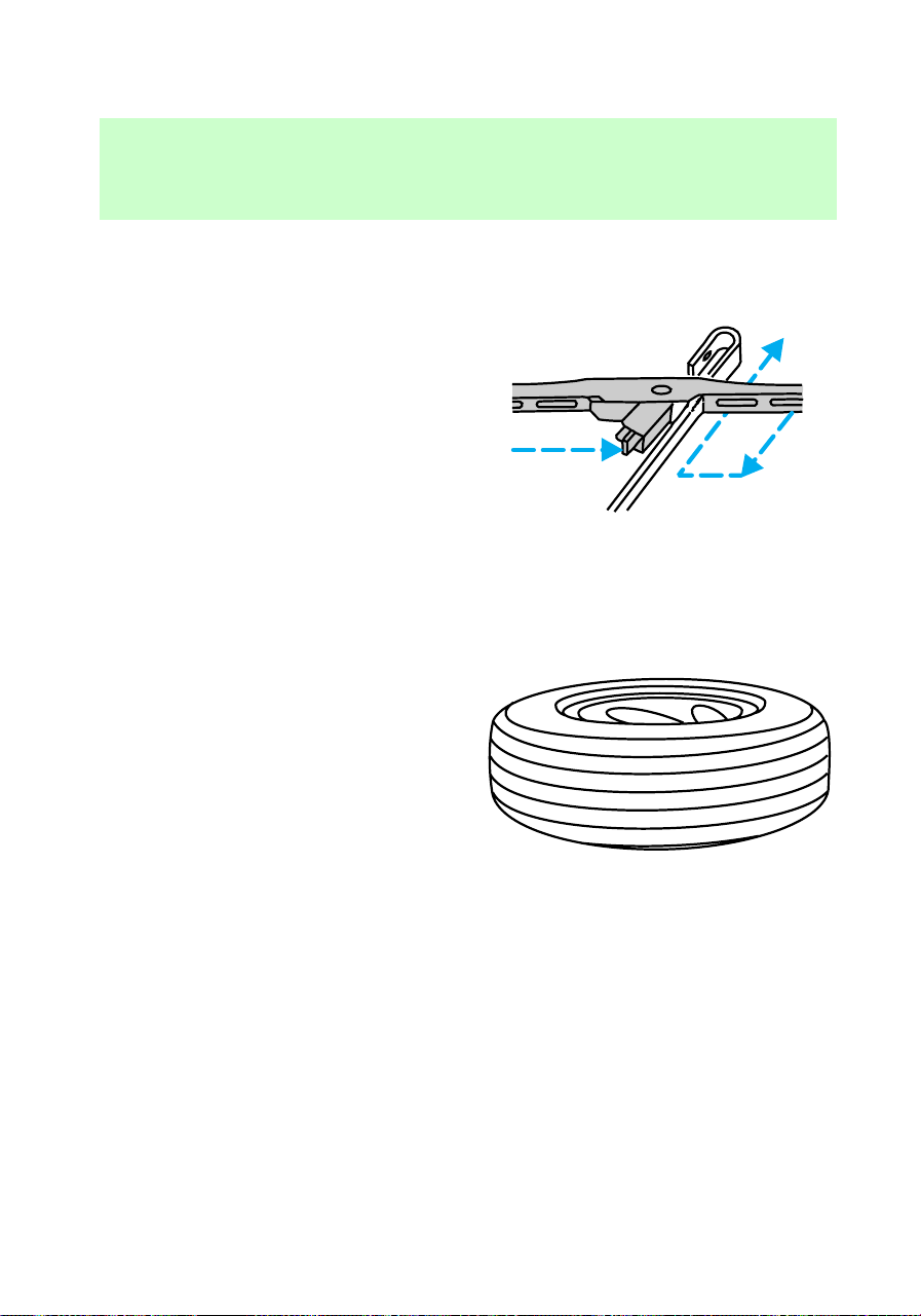
1. Pull the arm away from the
windshield and lock it into the
service position.
2. Turn the blade at an angle from
the wiper arm. Depress lock tab
and push wiper mounting arm
away from wiper blade assembly.
3. Attach new wiper blade by
pulling wiper mounting arm down
on wiper blade until lock tab is
engaged.
TIRES
Information about tire quality
grades
New vehicles are fitted with tires
that have their Tire Quality Grade
(described below) molded into the
tire’s sidewall. These Tire Quality
Grades are determined by
standards that the United States
Department of Transportation has
set.
Tire Quality Grades apply to new
pneumatic tires for use on
passenger cars. They do not apply
to deep tread, winter-type snow
tires, space-saver or temporary use
spare tires, tires with nominal rim
diameters of 10 to 12 inches or
limited production tires as defined
in Title 49 Code of Federal
Regulations Part 575.104(c)(2).
U.S. Department of
Transportation-Tire quality
grades: The U.S. Department of
Transportation requires Ford to
give you the following information
f12_maint_tires
com_about_tire_grades.01
Maintenance and care
182

about tire grades exactly as the
government has written it.
Treadwear
The treadwear grade is a
comparative rating based on the
wear rate of the tire when tested
under controlled conditions on a
specified government test course.
For example, a tire grade 150
would wear one and one-half (1
1/2) times as well on the
government course as a tire grade
100. The relative performance of
tires depends upon the actual
conditions of their use, however,
and may depart significantly from
the norm due to variations in
driving habits, service practices,
and differences in road
characteristics and climate.
Traction A B C
The traction grades, from highest
to lowest are A, B, and C, and they
represent the tire’s ability to stop
on wet pavement as measured
under test surfaces of asphalt and
concrete. A tire marked C may
have poor traction performance.
Warning: The traction grade
assigned to this tire is based on
braking (straightahead) traction
tests and does not include
cornering (turning) traction.
Temperature A B C
The temperature grades are A (the
highest), B, and C, representing
the tire’s resistance to the
generation of heat and its ability to
dissipate heat when tested under
com_treadwear.01
com_traction_abc.01
com_temperature_abc.01
Maintenance and care
183

controlled conditions on a
specified indoor laboratory test
wheel. Sustained high temperature
can cause the material of the tire
to degenerate and reduce tire life,
and excessive temperature can
lead to sudden tire failure. The
grade C corresponds to a level of
performance which all passenger
car tires must meet under the
Federal Motor Vehicle Safety
Standard No. 109. Grades B and A
represent higher levels of
performance on the laboratory test
wheel than the minimum required
by law.
The temperature grade for
this tire is established for a
tire that is properly inflated and
not overloaded. Excessive speed,
underinflation, or excessive
loading, either separately or in
combination, can cause heat
buildup and possible tire failure.
Servicing the tires
Checking the tire pressure
Check the tire pressure at least
once a month or after rotating
tires and inflate tires as necessary.
Tire pressure is most accurate
when tires are cold (after vehicle
has been parked for at least one
f12_servicing_tires
Maintenance and care
184
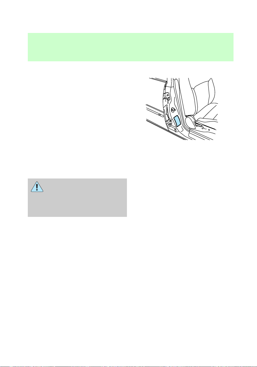
hour or driven less than 5 km [3
miles]).
The cold pressure amount is listed
on the Safety Compliance
Certification Label located on the
inside driver door latch pillar.
Improperly inflated tires
can affect vehicle handling
and can fail suddenly, possibly
resulting in loss of vehicle
control.
Rotating the tires
Rotate your tires at regular
intervals to ensure even wear.
Refer to the following diagrams for
rotation cycles. Rotation intervals
are listed in the “Service Guide.”
Your wheels and tires are
match-mounted for improved ride.
Before you begin a tire repair,
mark the wheel and tire to ensure
f12_rotating_tires
Maintenance and care
185

proper alignment when
remounting.
• Four-tire rotation
• Five-tire rotation
Replacing the tires
Replace the tires when the wear
band is visible through the tire
treads.
f12_replacing_tires
Maintenance and care
186

When replacing full size
tires, never mix radial,
bias-belted, or bias-type tires.
Use only the tire sizes that are
listed on the tire pressure decal.
Make sure that all tires are the
same size, speed rating, and
load-carrying capacity. Use only
the tire combinations
recommended on the decal. If
you do not follow these
precautions, your vehicle may
not drive properly and safely.
Make sure that all
replacement tires are of
the same size, type, load-carrying
capacity and tread design (e.g.,
“All Terrain”, etc.), as originally
offered by Ford.
Do not replace your tires
with “high performance“
tires or larger size tires.
Failure to follow these
precautions may adversely
affect the handling of the vehicle
and make it easier to lose control
and roll over.
Identifying tire types
Refer to the Safety Compliance
Certification Label to determine
the specific size tire and wheel
Ford Motor Company recommends
for use on this vehicle.
f12_iden_tire_types
f12_snow_tires
Maintenance and care
187

Snow tires and chains
Snow tires must be the
same size and grade as the
tires you currently have on your
vehicle.
The tires on your vehicle have all
weather treads to provide traction
in rain and snow.
However, in some climates, you
may need to use snow tires and
chains.
Follow these guidelines when using
snow tires and chains.
• Use only SAE Class “S” chains.
• Install chains securely, verifying
that the chains do not touch any
wiring, brake lines or fuel lines.
• 4x2: Install tire chains on rear
tires (of all sizes) only.
• 4x4: Install tire chains on rear
tires (of all sizes), and on front
tires of size P235/70R16 only.
• Drive cautiously. If you hear the
chains rub or bang against your
vehicle, stop and retighten the
chains. If this does not work,
remove the chains to prevent
damage to your vehicle.
• If possible, avoid fully loading
your vehicle.
• Remove the tire chains when
they are no longer needed. Do
not use tire chains on dry roads.
• The suspension insulation and
bumpers will help prevent
vehicle damage. Do not remove
Maintenance and care
188

these components from your
vehicle when using snow tires
and chains.
FUEL
Important safety precautions
Do not overfill the fuel
tank. The pressure in an
overfilled tank may cause
leakage and lead to fuel spray
and fire.
If you do not use the
proper fuel cap, the
pressure in the fuel tank can
damage the fuel system or cause
it to work improperly in a
collision.
The fuel system may be
under pressure. If the fuel
cap is venting vapor or if you
hear a hissing sound, wait until it
stops before completely
removing the cap.
Automotive fuels can
cause serious injury or
death if misused or mishandled.
f12_fuel_info
com_important_precautions.06
Maintenance and care
189
Observe the following guidelines
when handling automotive fuel:
• Extinguish all smoking materials
and any open flames before
fueling your vehicle.
• Always turn off the vehicle
before fueling.
• Automotive fuels can be harmful
or fatal if swallowed. If fuel is
swallowed, call a physician
immediately, even if no
symptoms are immediately
apparent. The toxic affects of
fuel may not be visible for
hours.
• Fuels can also be harmful if
absorbed through the skin. If
fuel is splashed on the skin,
promptly remove contaminated
clothing and wash skin
thoroughly with soap and water.
• If fuel is splashed in the eyes,
remove contact lenses, flush
with water for 15 minutes and
seek medical attention.
• Be particularly careful if you are
taking “Antabuse” or other
forms of disulfiram for the
treatment of alcoholism.
Breathing gasoline vapors or
skin contact could cause an
adverse reaction. Consult a
physician immediately.
Choosing the right fuel
Use only UNLEADED FUEL. The
use of leaded fuel is prohibited by
law and could damage your
com_choosing_fuel.01
Maintenance and care
190
vehicle. The damage may not be
covered by your warranty.
Your vehicle was not designed to
use fuel containing
manganese-based additives such as
MMT. Additionally, vehicles
certified to California emission
standards (indicated on the
underhood Vehicle Emissions
Control Information label) are
designed to operate on California
reformulated gasolines. If
California reformulated gasoline is
not available when you refuel, your
vehicle can be operated on
non-California fuels. However, even
though your engine will perform
adequately on other gasolines, the
performance of the emission
control devices and systems may
be adversely affected. Repair of
damage caused by using a fuel that
your vehicle was not designed for
may not be covered by your
warranty.
Octane recommendations
Your vehicle is designed to use
regular gasoline with an (R+M)/2
octane rating of 87. We do not
recommend gasolines labeled as
“regular” in high altitude areas that
are sold with octane ratings of 86
or even less.
Do not be concerned if your
vehicle sometimes knocks lightly.
However, if it knocks heavily under
most driving conditions on the
recommended octane fuel, see
87
com_octane_recommendations.01
Maintenance and care
191

your dealer or a qualified service
technician to prevent any engine
damage.
Fuel quality
If you are experiencing starting,
rough idle or hesitation problems
try a different brand of fuel. If the
condition persists, see your dealer
or a qualified service technician.
The American Automobile
Manufacturers Association (AAMA)
issued a gasoline specification to
provide information on high quality
fuels that optimize the
performance of your vehicle. We
recommend the use of gasolines
that meet the AAMA specification
if they are available.
It should not be necessary to add
any aftermarket products to your
fuel tank if you continue to use a
high-quality fuel.
Cleaner air
Ford approves the use of gasolines
to improve air quality, including
reformulated gasolines, that
contain oxygenates such as a
maximum of 10% ethanol or 15%
MTBE. There should be no more
than 5% methanol with cosolvents
and additives to protect the fuel
system.
Calculating fuel economy
To accurately calculate your
vehicle’s fuel economy:
1. Fill the tank completely and
record the initial odometer
reading.
com_fuel_quality.01
f12_cleaner_air
f12_calculating_economy
Maintenance and care
192

2. Each time you fill the tank,
record the amount of fuel added
(in liters or gallons).
3. After at least three to five fuel
tank fill-ups, fill the fuel tank and
record the current mileage
reading.
4. Use one of the following
equations to calculate fuel
economy.
Liters used x 100 4 Total
kilometers traveled = km/liter.
Total miles traveled 4 Total
gallons used = mpg.
5. Keep a record for at least one
month. This will provide an
accurate estimate of the vehicle’s
fuel economy.
f12_wysk_emission_control
Maintenance and care
193
WHAT YOU SHOULD KNOW
ABOUT THE EMISSION
CONTROL SYSTEM
Your vehicle is equipped with a
catalytic convertor which enables
your vehicle to comply with
applicable exhaust emission
requirements. For more
information on your vehicle’s
emission control system, see the
Vehicle Emission Control
Information decal located on the
left side of the engine
compartment.
Follow these guidelines to ensure
proper emission system operation:
• Use only unleaded fuel.
• Avoid running out of fuel.
• Do not turn off the ignition
while the vehicle is in motion.
• Have regular maintenance
checks performed according to
the intervals in the “Service
Guide.”
When servicing your vehicle, never
use a metal exhaust collector. A
metal collector may melt or deform
plastic parts.
Maintenance and care
194

Do not park, idle, or drive
your vehicle in dry grass
or other dry ground cover. The
emission system heats up the
engine compartment and exhaust
system, which can start a fire.
If you smell exhaust fumes
inside your vehicle, have
your dealer inspect your vehicle
immediately. Do not drive if you
smell exhaust fumes.
On vehicles without
original equipment floor
covering or insulation, do not let
passengers ride in your truck in
a manner that allows contact
between skin and the metal floor.
If you notice one or more of the
following, the emissions system
may not be working properly. Have
your vehicle serviced as soon as
possible.
• Fluid leaks
• The
or
CHECK
ENGINE
lights
illuminate in the instrument
cluster and remain lit
• Strange odors
• Engine runs more than five
seconds after shut-off or engine
misfires, surges, stalls or
backfires
• Loss of oil pressure.
f12_important_emissions_info
Maintenance and care
195

Important emission control
information
By law, anyone who manufacturers,
repairs, services, sells, leases,
trades vehicles or supervises a
fleet of vehicles is not permitted to
intentionally remove an emission
control device or prevent it from
working.
Do not make any unauthorized
changes to the vehicle or engine.
Changes that cause more
unburned fuel to reach the exhaust
system can increase the
temperature of the engine or
exhaust system.
Preparing your vehicle for
inspection/maintenance testing
In some localities it may become a
legal requirement to pass an
Inspection/Maintenance test of the
on-board diagnostic (OBDII)
system. If the vehicle’s powertrain
system or battery has just been
serviced, the OBD II system is
reset to a “not ready for I/M
testing condition.” To ready the
OBD II system for I/M testing, the
law specifies that additional mixed
city and highway driving is
necessary to complete the check of
the OBD II system.
The driving modes required to
reach the ready condition consist
of a minimum of 30 minutes of city
and highway driving as described
below:
f12_readiness_im_testing
Maintenance and care
196

• 20 minutes of driving in stop
and go city-type traffic with at
least four idle periods.
• 10 minutes of driving on an
expressway or highway.
Before completing the above
driving modes, the engine must be
warmed up and at operating
temperature. Once started, the
vehicle must not be turned off
during the above driving modes.
Maintenance and care
197
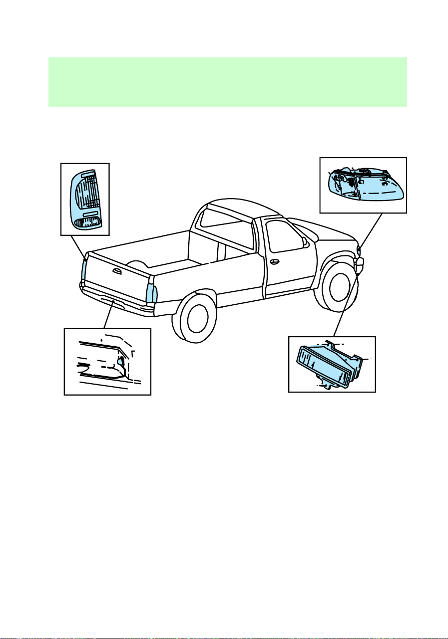
REPLACING BULBS
Replacing exterior bulbs
It is a good idea to check the
operation of the following lamps
frequently:
• Headlamps
• Tail lamps
• Brakelamps
• High-mount brakelamp
• Backup lamps
• Hazard flashers
• Turn signals
• License plate lamp
• Fog lamps
• Interior overhead lamps
f12_replacing_bulbs
Maintenance and care
198

Do not remove lamp bulbs unless
they will be replaced immediately.
If a bulb is removed for an
extended period of time,
contaminants may enter the lamp
and affect performance.
Replacing headlamp bulbs
Handle a halogen
headlamp bulb carefully
and keep out of children’s reach.
Grasp the bulb only by its plastic
base and do not touch the glass.
The oil from your hand could
cause the bulb to break the next
time the headlamps are
operated.
1. Make sure that the headlamp
control is in the position.
2. Open the hood.
3. At the back of the headlamp,
pull clips rearward and up 19 mm
(about 3/4 in.) to release the
headlamp assembly.
f12_headlamps_turnsignals
Maintenance and care
199
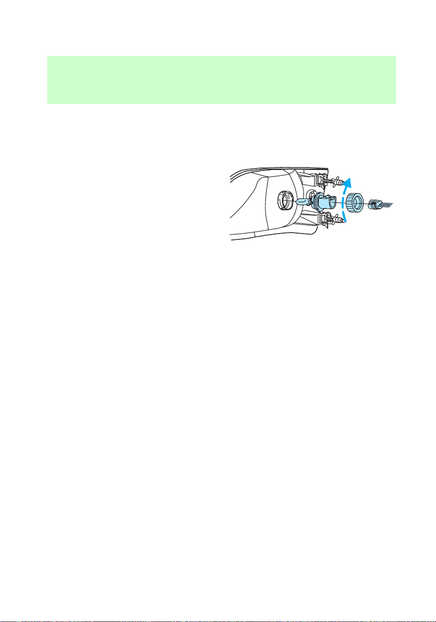
4. Slide headlamp assembly
forward and off of guide ribs to
expose the back of the bulb and
wiring connector.
5. Remove the electrical connector
from the bulb by grasping the wire
and pulling it rearward.
6. Remove bulb retainer ring by
turning it counterclockwise about
1/4 turn, then slide the ring off the
plastic base.
7. Without turning, carefully pull
bulb assembly out of headlamp
assembly.
8. Insert the glass end of the new
bulb into the headlamp assembly
socket. When the grooves in the
plastic base are aligned, push the
bulb into the socket until the
plastic base contacts the rear of
the socket.
9. Slip bulb retaining ring over the
plastic base and lock the ring into
the socket by turning it clockwise
until you feel a “stop.”
10. Push the electrical connector
into the rear of the plastic base
until it “snaps.”
Maintenance and care
200
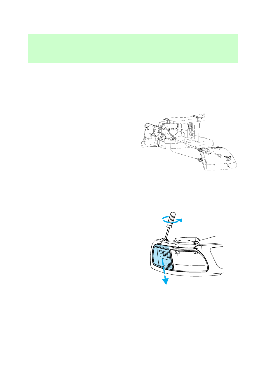
11. Straighten alignment pins,
making them parallel with the
outer edges of the attachment
standoff.
12. Carefully insert the headlamp
assembly into the vehicle making
sure the alignment pins are
inserted into the proper holes and
into the guide ribs.
13. Hold the headlamp assembly
snugly against the vehicle and
push down on the clips to lock the
lamp into position.
Replacing parking lamp/turn
signal bulbs
1. Remove screw from the top of
lamp assembly.
Maintenance and care
201
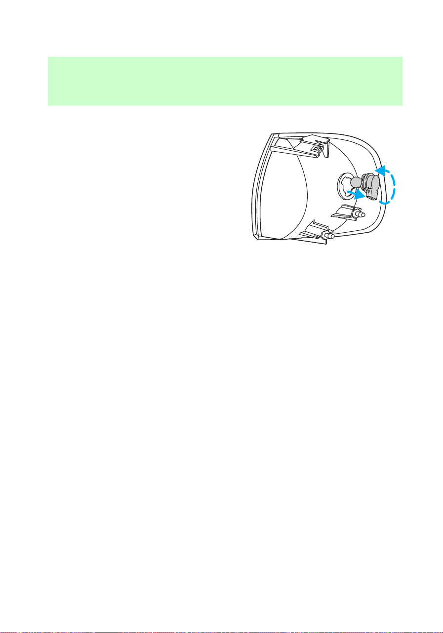
2. Disengage lamp assembly (it has
a snap fit).
3. Remove the electrical connector
from the bulb by grasping the wire
and pulling it rearward.
4. Remove bulb retainer ring by
turning it counterclockwise about
1/4 turn, then slide the ring off the
plastic base.
5. Without turning, carefully pull
bulb assembly out of parking lamp
assembly.
6. Insert the glass end of the new
bulb into the parking lamp
assembly socket. When the grooves
in the plastic base are aligned,
push the bulb into the socket until
the plastic base contacts the rear
of the socket.
7. Slip bulb retaining ring over the
plastic base and lock the ring into
the socket by turning it clockwise
until you feel a “stop.”
8. Push the electrical connector
Maintenance and care
202
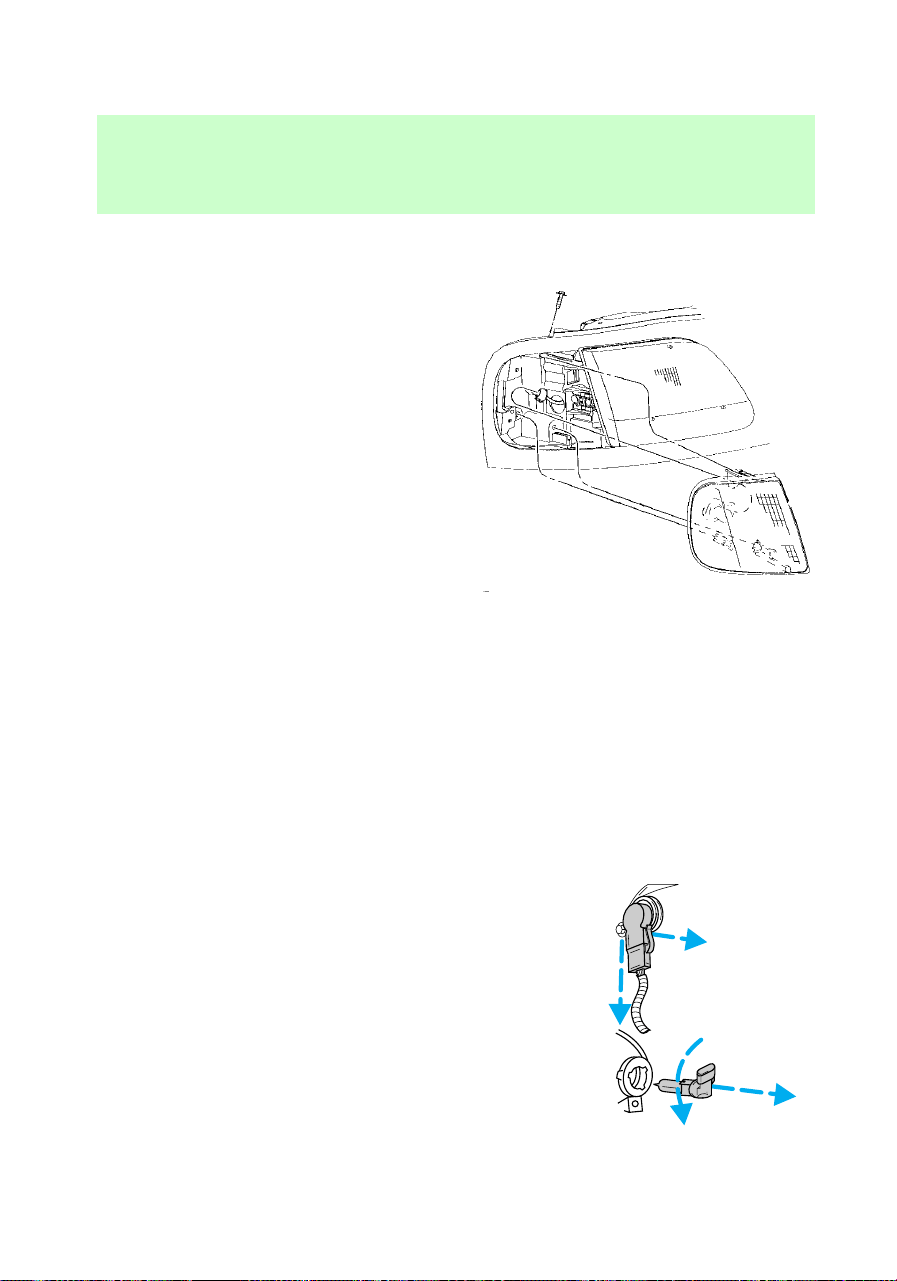
into the rear of the plastic base
until it “snaps.”
9. Align top and bottom ribs of
parking lamp assembly with
corresponding slots on front of
vehicle.
10. Push gently until parking lamp
assembly seats (you will hear a
snap).
11. Replace screw removed in step
1.
Replacing foglamp bulbs
1. Disconnect the electrical
connector from the back of the
foglamp assembly.
2. Twist, then pull the bulb from
the foglamp assembly.
3. Install the new bulb.
4. Connect the electrical connector
to the back of the foglamp
assembly.
f12_foglamps
f12_tail_lamps
Maintenance and care
203
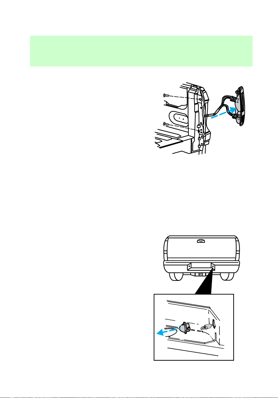
Replacing tail lamp/backup
lamp bulbs
1. Remove the two bolts from the
inside of the tailgate.
2. Carefully pull the tail lamp and
backup lamp assembly from the
tailgate pillar by releasing the two
retaining tabs.
3. Disconnect the bulb connector.
4. Pull out the bulb to be replaced.
5. Install a new bulb.
6. Carefully insert the tail lamp
and backup lamp assembly,
snapping the two retaining tabs
into place.
7. Install the two bolts.
Replacing license plate lamp
bulbs
1. Carefully pull the license plate
lamp lens from the rear bumper.
2. Remove the bulb to be replaced
and install a new bulb.
3. Install the license plate lamp
lens.
f12_license_plate_lamps
f12_dome_lamp
Maintenance and care
204
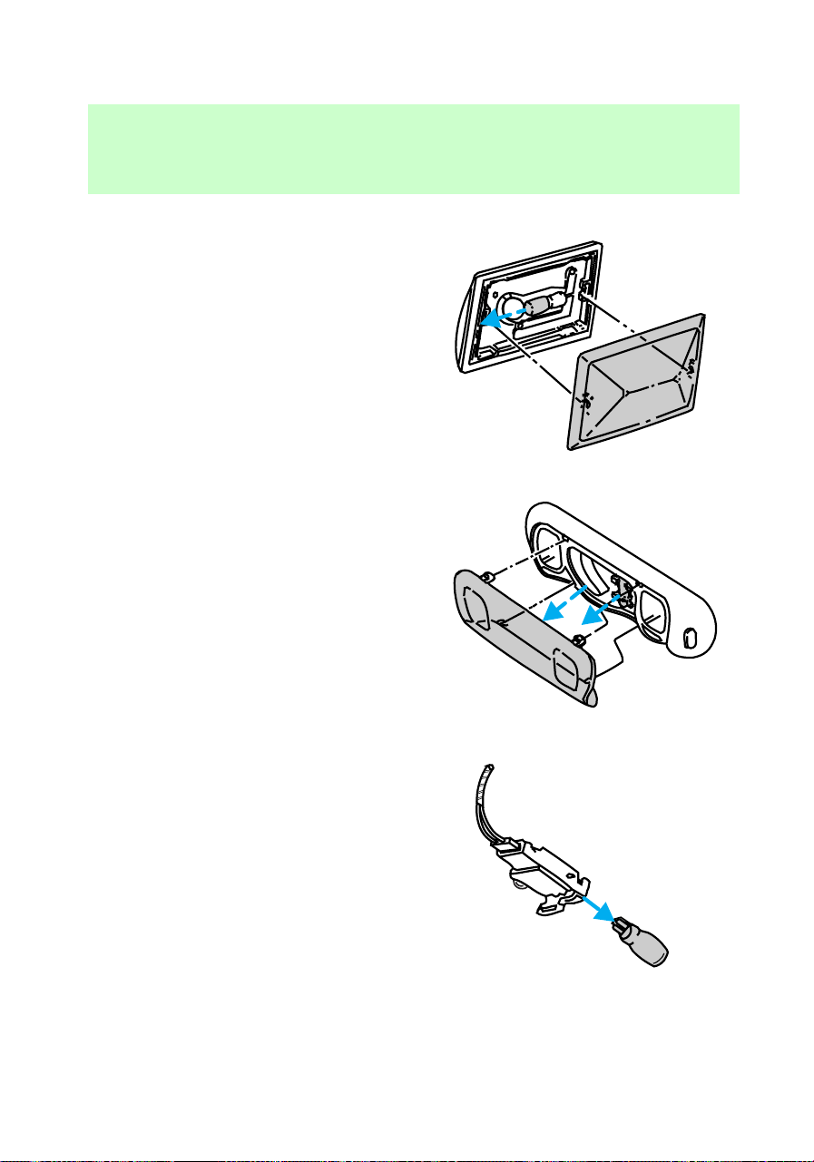
Replacing dome lamp bulb (if
equipped)
1. Carefully pull the dome lamp
lens from the lamp assembly.
2. Remove the dome lamp bulb
and replace it with a new bulb.
3. Carefully snap the dome lamp
lens into the dome lamp assembly.
Replacing dome/map lamp bulb
(if equipped)
1. Carefully pull the dome/map
lamp lens from the lamp assembly.
2. Remove the dome/map lamp
bulb and replace it with a new
bulb.
3. Carefully snap the dome lamp
lens into the dome/map lamp
assembly.
Replacing engine compartment
lamp bulb (if equipped)
1. Open the hood.
2. Carefully pull the engine
compartment lamp bulb from the
lamp assembly and replace with a
new bulb.
f12_dome_map_lamp
f12_engine_compart
f12_exterior_bulb_specs
Maintenance and care
205

Exterior bulb specifications
Function Number of
bulbs
Trade number
Front park/turn lamps 2 3157NAK
Foglamps 2 9006
Headlamps 2 9007
Rear turn/sidemarker 2 3157NAK
AIMING HEADLAMPS
The alignment of your headlamps
should be checked if:
• Oncoming motorists frequently
signal you to turn off your
vehicle’s high beams when you
do not have the high beams on.
• The headlamps do not seem to
give you enough light to see
clearly at night.
• The headlamp beams are
pointed substantially away from
a position slightly down and to
the right.
See your Ford dealer for precise
headlamp adjustment.
Cleaning and caring for your
vehicle
Refer to the “Customer Assistance
Guide” for a list of Ford-approved
cleaners, polishes and waxes.
f12_aiming_hlamps
f12_cleaning_your_vehicle
com_cleaning_caring.01
com_washing_vehicle.01
Maintenance and care
206

Washing your vehicle
Wash your vehicle regularly with
cold or lukewarm water. Never use
strong detergents or soap. If your
vehicle is particularly dirty, use a
quality car wash detergent. Always
use a clean sponge, washing glove
or similar device and plenty of
water for best results. To avoid
spots, avoid washing when the
hood is still warm, immediately
after or during exposure to strong
sunlight.
During winter months, it is
especially important to wash the
vehicle on a regular basis. Large
quantities of dirt and road salt are
difficult to remove, and they also
cause damage to the vehicle.
Remove any exterior accessories,
such as antennas, before entering
a car wash.
• After washing, apply the brakes
several times to dry them.
Waxing your vehicle
The best way to determine when
the paintwork needs waxing is by
noting when water stops beading
on the surface. This could be every
three or four months, depending
on operating conditions.
Use only carnauba or
synthetic-based waxes. Remove
any bugs and tar before waxing
vehicle. Use cleaning fluid or
alcohol with a clean cloth to
remove. Use tar remover to
remove any tar spots.
com_waxing_vehicle.01
com_repairing_chips
Maintenance and care
207
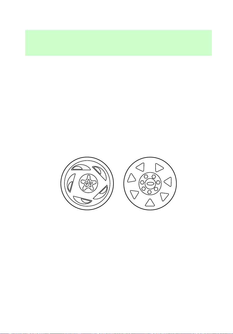
Repairing paint chips
Minor scratches or paint damage
from road debris may be repaired
with touch-up paint, paint repair
foil or aerosol paint spray from the
Ford accessory line. Observe the
application instructions on the
products.
Remove particles such as bird
droppings, tree sap, insect
remains, tar spots, road salt and
industrial fallout immediately.
Cleaning the wheels
Wash the wheels with the same
detergent you use to clean the
body of your vehicle. Do not use
acid-based wheel cleaners, steel
wool, fuel or strong detergents.
Never use abrasives that will
damage the finish of special wheel
surfaces. Use a tar remover to
remove grease and tar.
Cleaning the engine
Engines are more efficient when
they are clean because grease and
f12_cleaning_wheels
com_engine_cleaning.01
Maintenance and care
208
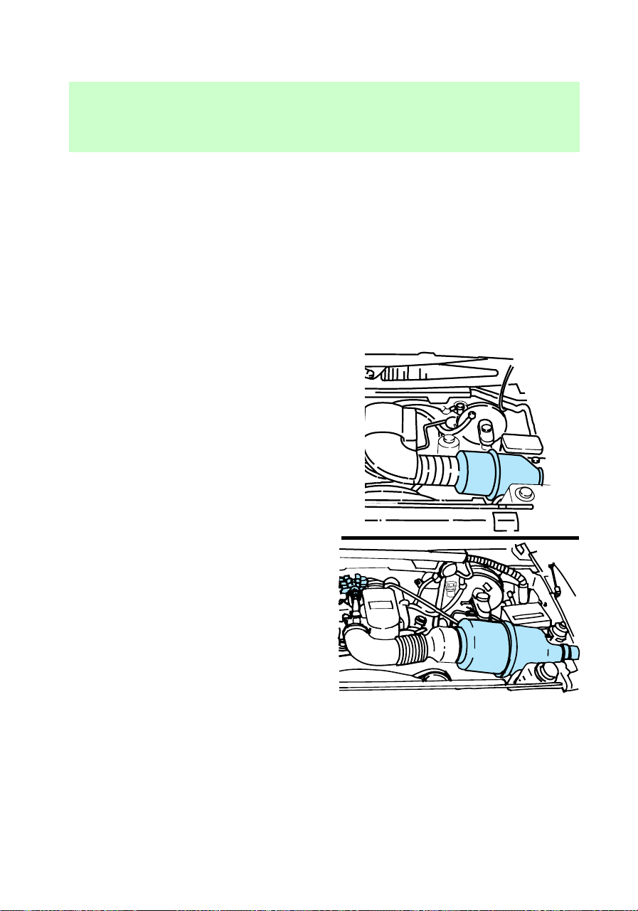
dirt buildup act as insulators and
keep the engine warmer than
normal. Follow these guidelines to
clean your engine:
• Take care when using a power
washer to clean the engine. The
high pressure fluid could
penetrate the sealed parts and
cause damage.
• Do not spray with cold water to
avoid cracking the engine block.
• Cover the highlighted areas to
prevent water damage when
cleaning the engine.
• Never wash or rinse the engine
while it is running; water in the
running engine may cause
internal damage.
Cleaning plastic exterior parts
Use a vinyl cleaner for routine
cleaning of plastic. Clean with a tar
remover if necessary. Do not clean
com_plastic_exterior.01
Maintenance and care
209
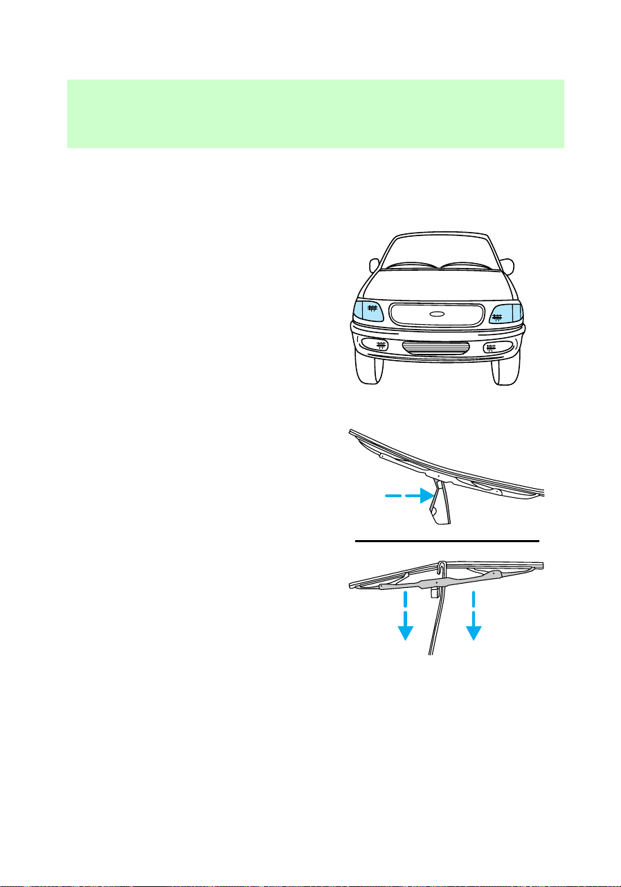
plastic parts with thinners,
solvents or petroleum-based
cleaners.
Cleaning the exterior lamps
Wash the exterior lamps with the
same detergent you used to wash
the exterior of your vehicle. Use
glass cleaner or tar remover if
necessary.
To avoid scratching the lamps, do
not use a dry paper towel,
chemical solvents or abrasive
cleaners to clean the lamps.
Cleaning the wiper blades
If the wiper blades do not wipe
properly, clean both the windshield
and wiper blades using undiluted
windshield wiper solution or a mild
detergent. Rinse thoroughly with
clean water. To avoid damaging the
blades, do not use fuel, kerosene,
paint thinner or other solvents.
com_exterior_lamps.01
com_wiper_cleaning.01
com_instru-panel_cleaning.01
Maintenance and care
210
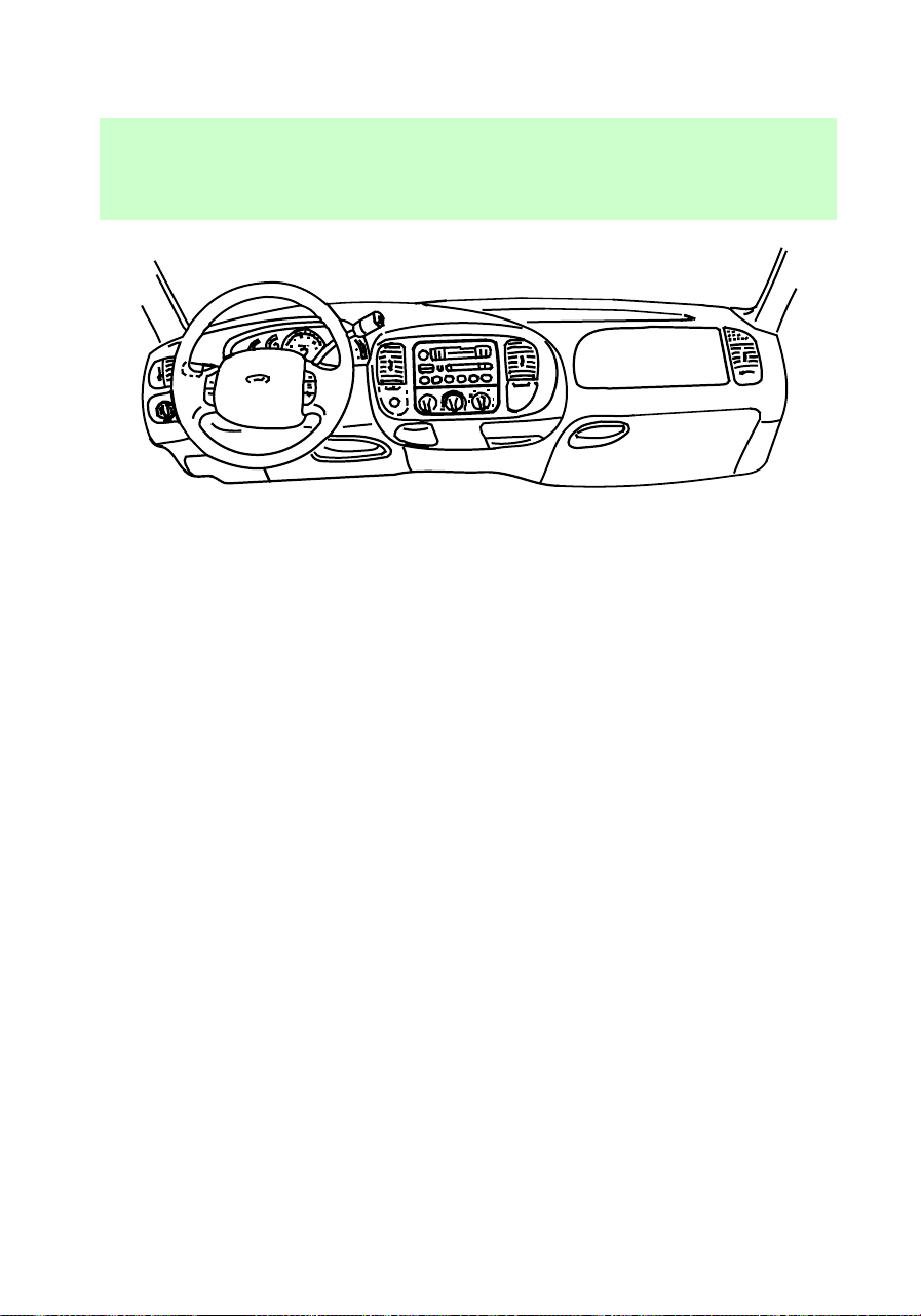
Cleaning the instrument panel
Clean instrument panel with a
damp cloth, then dry with a dry
cloth.
Any cleaner or polish that
increases the gloss of the upper
portion of the instrument panel
should be avoided. The dull finish
in this area is to help protect the
driver from undesirable windshield
reflection.
Cleaning the interior fabric
Remove dust and loose dirt with a
whisk broom or a vacuum cleaner.
Remove fresh spots immediately.
Follow the directions that come
with the cleaner.
Cleaning leather seats (if
equipped)
For routine cleaning, wipe the
surface with a soft, damp cloth.
For more thorough cleaning, wipe
the surface with a leather and
vinyl cleaner or a mild soap.
com_int_fabric_cleaning.01
com_leather_seats_cleaning.01
f12_cleaning_safety_belts
Maintenance and care
211

Cleaning and maintaining the
safety belts
Clean the safety belts with a mild
soap solution recommended for
cleaning upholstery or carpets. Do
not bleach or dye the belts,
because these actions may weaken
the belt webbing.
Check your safety belt system
periodically to make sure that it
works properly and is not
damaged. If the webbing shows
any wear, nicks or cuts, have it
examined by a qualified technician
to determine if replacement is
necessary. Always have your safety
belt system checked after a
collision by a qualified technician.
Refer to Safety belt maintenance
in the Seating and safety
restraints chapter for more
information.
Maintenance and care
212
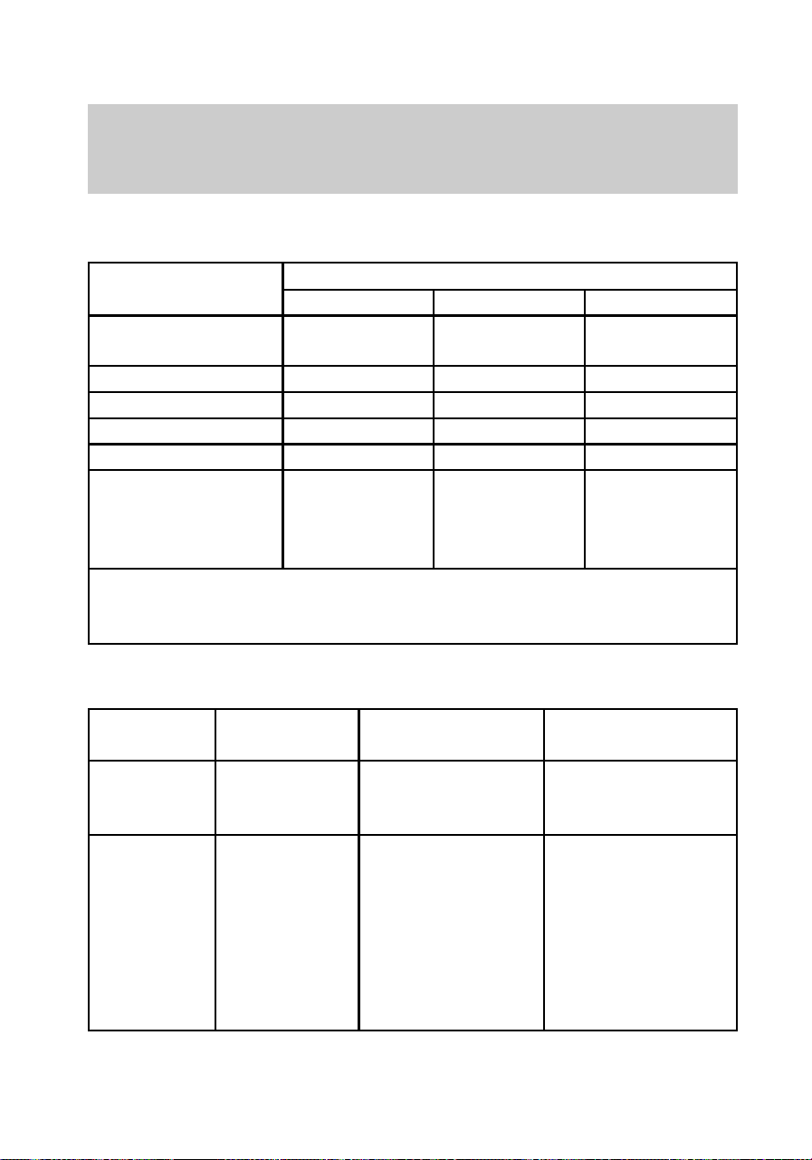
MOTORCRAFT PART NUMBERS
Component
Engine
4.2L 4.6L 5.4L
Spark
plug-platinum
1
AWSF-42EE AWSF-32PP AWSF-22F
Air filter FA-1632 FA-1632 FA-1632
Fuel filter FG-872 FG-872 FG-872
Oil filter FL-400-S FL-820-S FL-820-S
PCV valve EV-152 EV-98 EV-233
Battery
BXT-59
(manual)
BXT-65-750
(automatic)
BXT-59
(manual)
BXT-65-750
(automatic)
BXT-59
(manual)
BXT-65-750
(automatic)
1
Replacement double platinum spark plug 9EE9 will replace 9E9 and
9EG9 and 9P9 will replace 9P9 and 9PG9 suffixed plugs. Refer to the
Engine data chart for spark plug gap specifications.
REFILL CAPACITIES
Fluid
Ford part
name
Vehicle type Capacity
Axle; front
Ford 22.35
cm (8.8 in)
Ring Gear
4WD 1.65L (3.5 pts.)
Axle; rear
Ford 22.35
cm (8.8 in)
and 24.76 cm
(9.75 in) Ring
Gear
Conventional
and Traction
-Lok(1)
F-150 2.6L (5.5 pts.)
f12_motorcraft_part
f12_refill
Capacities and specifications
213

Fluid
Ford part
name
Vehicle type Capacity
Axle; rear
Ford 26.03
cm (10.25 in)
Conventional
and Traction
Lok (2)
F-250 3.3L (7.0 pts.)
Engine
coolant
Premium
Cooling
System Fluid
4.2L w/o A/C
4.2L with A/C
4.6L w/o A/C
4.6L with A/C
5.4L w/o A/C
5.4L with A/C
14.9L (15.7 qts.)
16.4L (17.3 qts.)
16.9L (17.9 qts.)
18.4L (19.4 qts.)
16.9L (17.9 qts.)
18.3L (19.4 qts.)
Engine oil
1
Super
Premium
Motorcraft
Motor Oil
5W-30
4.2L
4.6L
5.4L
5.7L (6.0 qts.)
5.7L (6.0 qts)
5.7L (6.0 qts.)
Fuel
Unleaded 87
octane
4x2 Reg. Cab
4x2 SuperCab
4x4 Reg. Cab
4x4 SuperCab
Long Wheelbase
94.6L (25.0 gal)
94.6L (25.0 gal)
92.7L (24.5 gal)
94.6L (25.0 gal)
113.6L (30.0 gal)
Power
steering
fluid
Motorcraft
MERCONT
Multi-purpose
ATF
All 2.3L (2.4 pts.)
Transfer
case
fluid
3
(if
equipped)
Motorcraft
MERCONT
Multi-purpose
ATF
4-wheel drive
transfer case
1.9L (2.0 qts.)
Transmission
fluid;
automatic
Motorcraft
MERCONT
Multi-purpose
ATF
4R70W
E4OD (4x2)
E4OD (4x4)
13.1L (13.9 qts.)
15.04L (15.9 qts.)
15.51L (16.4 qts.)
Capacities and specifications
214

Fluid
Ford part
name
Vehicle type Capacity
Transmission
fluid;
manual
2
Motorcraft
MERCONT
Multi-purpose
ATF
5-speed manual 3.5L (3.75 qts.)
Windshield
washer fluid
Ultra-clear
windshield
washer fluid
concentrate
All 4.0L (4.25 qts.)
(1) Add 118 ml (4 oz.) of additive friction modifier C8AZ-19B546-A,
Ford specification EST-M2C118–A, for complete fill of 22.35 cm (8.8
in.) and 24.76 cm (9.75 in) ring gear Traction-Lok axles.
(2) Add 236 ml (8 oz.) of additive Friction Modifier C8AZ-19B546-A,
Ford Specification EST-M2C118-A, for complete fill of 26.03 cm
(10.25 in) Ring Gear Traction-Lok axles.
1
Includes filter replacement.
2
Fill to 6 mm (3/8 in) below
bottom of filler hole.
3
Fill to bottom of filler hole.
LUBRICANT SPECIFICATIONS
Fluid
Ford part name
or equivalent
Ford part
number
Ford
specification
Axle lubricant;
front
SAE 75W90 XY-75W90-QL
(Thermally
Stable)
WSP-M2C201-A
Axle lubricant;
rear
High
Performance
Rear Axle
Lubricant
F1TZ-19580-B WSL-M2C192-A
f12_lube
Capacities and specifications
215

Fluid
Ford part name
or equivalent
Ford part
number
Ford
specification
Brake fluid and
clutch fluid
High
Performance
DOT 3 brake
fluid
C6AZ-19542-AB ESA-M6C25-A
and DOT 3
Engine coolant
Premium engine
coolant
E2FZ-19549-AA
or B
ESE-M97B44-A
Engine oil
Super Premium
Motorcraft Motor
Oil 5W30
XO-5W30-BSP
or QSP
WSS-M2C153-F
Grease; body
hinges, latches
and seat tracks.
Multi-Purpose
Grease
D0AZ-19584-AA
or
D7AZ-19584-AA
ESB-M1C93-A
or
ESB-M1C106-B
Grease;
transmission
/steering/parking
brake linkages
and pivots.
Brake and
clutch pedal
shaft.
Premium
Long-Life
Grease
XG-1-C ESA-M1C75-B
Parking brake
cable
Speedometer
cable lubricant
E6TZ-19581-A ESF-M1C60-A
Power steering
fluid, transfer
case fluid and
transmission
fluid (manual
and automatic)
Motorcraft
MERCONT
Multi-purpose
ATF
XT-2-BDX or
QDX
MERCONT
Windshield
washer fluid
Ultra-clear
windshield
washer
concentrate
C9AZ-19550-AC
or BC
ESR-M17P5-A
Capacities and specifications
216

ENGINE DATA
General
Specifications
Engine
OHV 4.2L V-6 SOHC 4.6L V8 SOHC 5.4L V8
Displacement
4.2 L (256.2
CID)
4.6 L (280.6
CID)
5.4 L (329.4
CID)
Bore x stroke
96.8 mm x 95.0
mm
90.2 mm x 90
mm
90.2 mm x
105.8 mm
Horsepower
205 @ 4750
RPM
210 @ 4400
RPM
N/A*
Torque
260 ft. lb. @
3000 RPM
290 ft. lb. @
3250 RPM
N/A*
Required fuel
grade
Unleaded - 87
octane
Unleaded - 87
octane
Unleaded - 87
octane
Induction
system
Split port, OHV Tuned runner
and plenum
Tuned runner
and plenum
Firing order 1-4-2-5-3-6 1-3-7-2-6-5-4-8 1-3-7-2-6-5-4-8
Spark plug gap
.137 cm (.054
in)
.137 cm (.054
in)
.137 cm (.054
in)
Ignition system E.I. E.I. Coil on plug
Compression
ratio
9.2:1 9.0:1 9.0:1
*Not available at time of printing.
f12_engine_data
f12_vehicle_dimensions
Capacities and specifications
217
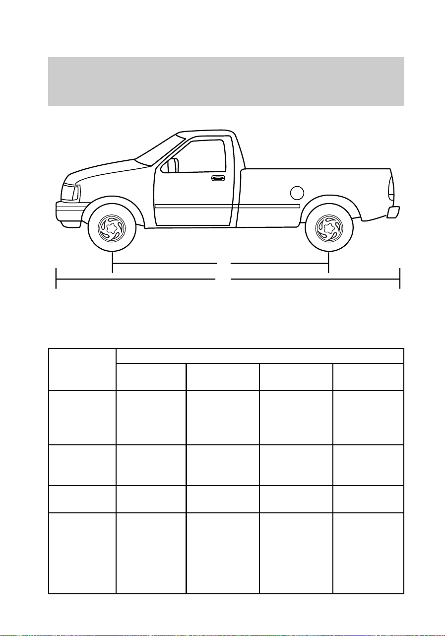
VEHICLE DIMENSIONS
STYLESIDE
Dimension
Body Style
Regular
Cab 4x2
Regular Cab
4x4
Super Cab
4x2
Super Cab
4x4
A=Overall
height
1.84 m (72.7
in) (SWB)
1.83 m (72.4
in) (LWB)
1.91 m (75.5
in) (SWB)
1.90 m(75.1
in) (LWB)
1.84 m (72.7
in) (SWB)
1.83 m (72.4
in)(LWB)
1.91 m (75.5
in) (SWB)
1.90 (75.1
in)(LWB)
B=Track
front/rear
1.66 m (65.4
in)/1.66 m
(65.4 in)
1.66 m (65.4
in)/1.66 m
(65.4 in)
1.66 m (65.4
in)/1.66 m
(65.4 in)
1.66 m (65.4
in)/1.66 m
(65.4 in)
C=Overall
width
1.99 m
(78.4 in)
1.99 m
(78.4 in)
1.99 m
(78.4 in)
2.01 m
(79.5 in)
D=Wheel
base
3.04 m
(119.9
in)(SWB)
3.51 m
(138.5
in)(LWB)
3.04 m
(119.9
in)(SWB)
3.51 m
(138.5
in)(LWB)
3.51 m
(138.5
in)(SWB)
3.99 m
(157.1 in)
(LWB)
3.51 m
(138.5
in)(SWB)
3.99 m
(157.1
in)(LWB)
D
E
f12_styleside
Capacities and specifications
218
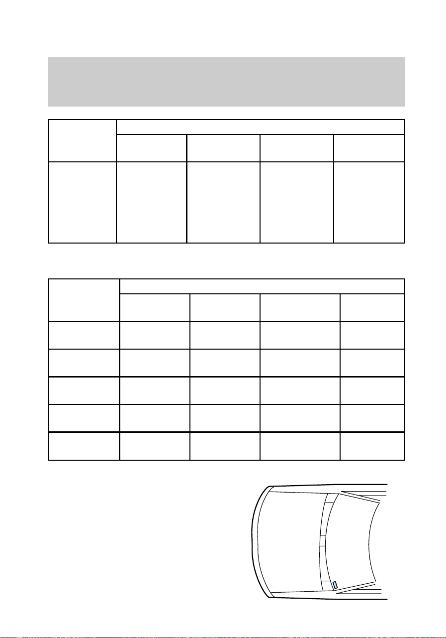
Dimension
Body Style
Regular
Cab 4x2
Regular Cab
4x4
Super Cab
4x2
Super Cab
4x4
E=Overall
length
5.13 m
(202.2
in)(SWB)
5.60 m
(220.8
in)(LWB)
5.13 m
(202.2
in)(SWB)
5.60 m
(220.8
in)(LWB)
5.6 m
(220.8
in)(SWB)
6.11 m
(240.9
in)(LWB)
5.6 m
(220.8
in)(SWB)
6.11 m
(240.9
in)(LWB)
FLARESIDE
Dimension
Body Style
Regular
Cab 4x2
Regular
Cab 4x4
Super Cab
4x2
Super Cab
4x4
A=Overall
height
1.84 m
(72.7 in)
1.91 m
(75.5 in)
1.84 m
(72.7 in)
1.91 m
(75.5 in)
B=Track
front/rear
1.66 m
(65.4 in)
1.66 m
(65.4 in)
1.66 m
(65.4 in)
1.66 m
(65.4 in)
C=Overall
width
2.00 m
(79.1 in)
2.00 m
(79.1 in)
2.00 m
(79.1 in)
2.00 m
(79.1 in)
D=Wheel
base
3.04 m
(119.9 in)
3.05 m
(120.2 in)
3.51 m
(138.5 in)
3.52 m
(138.8 in)
E=Overall
length
5.22 m
(205.9 in)
5.26 m
(207.4 in)
5.7 m
(224.5 in)
5.74 m
(226.0 in)
VEHICLE IDENTIFICATION
NUMBER (VIN)
The Vehicle Identification Number
(VIN) is attached to a metal tag
and is located on the driver side
instrument panel (the tag may be
read by looking through the
windshield from the outside of the
vehicle).
f12_flareside
f12_vin
Capacities and specifications
219

REPORTING SAFETY DEFECTS
If you believe that your vehicle has
a defect that could cause a crash,
or could cause injury or death, you
should immediately inform the
National Highway Traffic Safety
Administration (NHTSA) in
addition to Ford Motor Company.
If NHTSA receives similar
complaints, it may open an
investigation, and if it finds that a
safety defect exists in a group of
vehicles, it may order a recall and
remedy campaign. However,
NHTSA cannot become involved in
individual problems between you,
your dealer or Ford Motor
Company.
To contact NHTSA, you may either
call the Auto Safety Hotline
toll-free at 1–800–424–9393
(202–366–0123 in the Washington
D.C. area) or write to:
NHTSA
U.S. Department of Transportation
400 Seventh Street
Washington D.C. 20590
You can also obtain other
information about motor vehicle
safety from the Hotline.
f12_reporting
Reporting safety defects
220