Loading ...
Loading ...
Loading ...
12
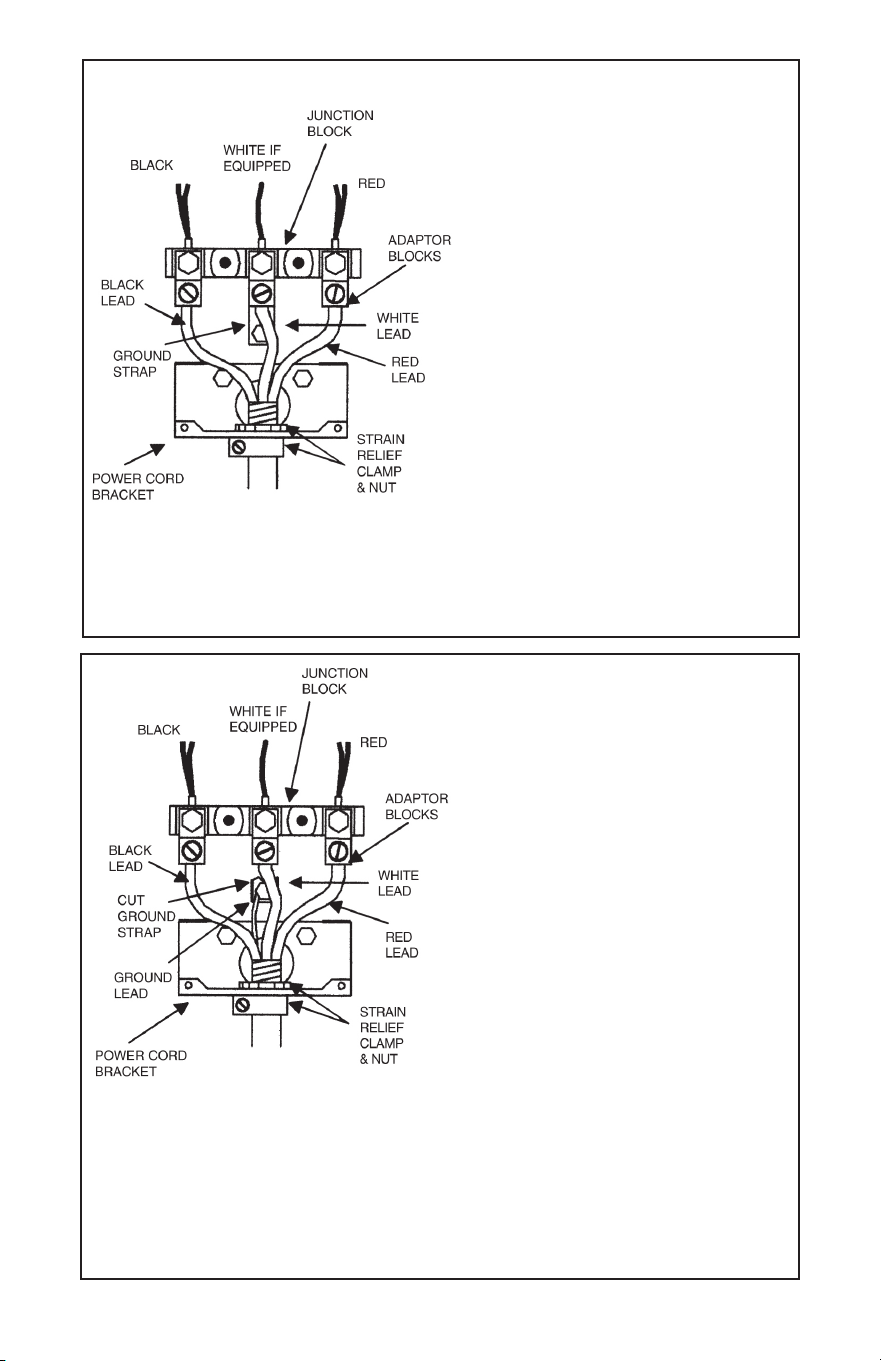
THREE-WIRE CONDUIT CONNECTION
NOTE: The power cord bracket will have
to be reversed for conduit installations.
Detach the bracket and ip its orientation.
Reattach the bracket to the range so the
conduit will pass through the smaller hole.
1. Remove the top nuts on the junction
block studs.
2. Tighten the back nuts.
3. Install the terminal adaptor blocks for
bar wire connection. Use the top nuts
removed in step 1.
4. Install the three-wire conduit and an
appropriate strain relief clamp through
the hole in the power cord bracket.
5. Insert the red and black leads into
the outer blocks and the white lead into
the center block. Tighten the set screws.
6. Secure the strain relief clamp around the
conduit and tighten the nut against the
power cord bracket.
120/240 or 240 VAC
120/240 VAC
If local codes do not allow grounding
through the neutral, refer to the
illustration below of FOUR-WIRE
CONDUIT CONNECTION.
FOUR-WIRE CONDUIT CONNECTION
NOTE: The power cord bracket will have
to be reversed for conduit installations.
Detach the bracket and ip its orientation.
Reattach the bracket to the range so the
conduit will pass through the smaller hole.
1. Remove the top nuts on the junction
block studs. Then, tighten the back nuts.
2. Cut the ground strap as close to the
junction block as possible and at
the lower section with upturned sides.
3. Install the four-wire conduit and an
appropriate strain relief clamp through
the hole in the power cord bracket.
4. Use the section of ground strap with
upturned sides and the ground screw to
connect the ground lead below the
junction block.
5. Install the terminal adaptor blocks for
bar wire connection. Use the top nuts
removed earlier in step 1.
6. Insert the red and black leads into
the outer blocks and the white lead into
the center block. Tighten the set screws.
7. Secure the strain relief clamp around the
conduit and tighten the nut against the
power cord bracket.
Effective January 1, 1996 the National Electrical
Code requires that new construction (not
existing) utilize a 4-conductor connection to an
electric range.
NOTE: A 4-conductor connection is to be
used when the appliance is installed in a
mobile home or when local codes do not permit
grounding through the neutral.
21
ALIGNMENTS AND ADJUSTMENTS
Oven Door Spring Adjustments
The oven door springs are properly adjusted before leaving the factory. The springs should
be adjusted to allow the door to remain open when pulled 90 degrees forward and yet pull
the door tight against the oven front frame when closed. If adjustments should become
necessary, remove the storage drawer and grasp spring with ngers, and pull downward.
To give more tension, push toward rear of range and attach in rst slot. To make spring
adjustment on ranges without storage drawer, remove false panel and follow the same
procedure.
Make certain all surface elements are
cool and all switches are in the OFF
position prior to seating elements.
Seating Top Elements
The top element may need initial
seating after installation of the stove
or after they have been unplugged and
re-installed. Palm the element as
shown. Pick up on the rear section
with your ngers, while at the same
time, push down on the front of the
element with the palm of your hand.
Storage
Your electric range is equipped with a
storage area located beneath the oven cavity.
To access this compartment, gently lift on
the front edge of the “drop-down” panel and
let it fall forward as shown. ONLY LIFT ON
THE FRONT EDGE OF THE PANEL SO
AS TO NOT PINCH YOUR FINGERS. Do
not use this panel as a step or shelf.
Coil Logic System
Some models may be equipped with Brown’s
exclusive Coil Logic safety system. It is designed
to prevent overheating by utilizing an automatic
cut-off sensor to power off the coil element if
higher than necessary temperatures are detected.
Once cooled, these sensors will disengage,
allowing power to return to the coil element.
The Coil Logic safety sensors are visible from the
top of the burner bowl (refer to gure). When the
coil elements are off and cool, the drip pans and
Coil Logic sensors can be cleaned with
mild soap and warm water. Dry thoroughly before resuming use. Always keep all
surfaces and subtop areas clean for optimal operation. Do not use aluminum foil
to line the drip pans. Improper use of aluminum foils may result in shock or re
hazard.
Loading ...
Loading ...
Loading ...