Loading ...
Loading ...
Loading ...
SIDE BURNER ACCESSORY CARE & USE/INSTALLATION
|
11
L
P GA
S
Accessories set up for LP gas come equipped with an LP hose
/
regulator assembly for connection to a standard 20 lb. LP
c
y
linder. (T
y
pe 1).
All ttings necessary to attach the assembly to the accessory are
included
.
Permanentl
y
plumbed LP connections, such as those in line with
a bulk c
y
linder, require a 4/11 regulator.
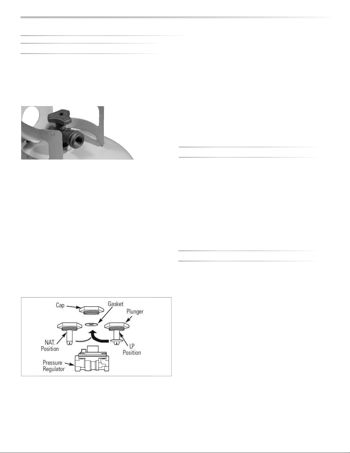
W
hen using the 4/11 regulator
y
ou must ensure that it is set
for the proper fuel t
y
pe. This is done b
y
removing the regulator
cap and gasket and looking at the bottom of the plunger to see
what fuel t
y
pe is visible. This is the regulator fuel setting. NAT is
for natural gas and LP is for propane gas. The LP setting can be
further identi ed by the large diameter disk on the bottom o
f
the plunger. To change from one gas to the other simpl
y
push
the plunger to the side to snap it out of the cap, turn the plunger
so it reads the desired gas type on the bottom, and push the
plun
g
er until it snaps back into place in the cap then replace the
cap into the re
g
ulator.
Never connect an unre
g
ulated
g
as line to the
g
rill.
W
hen exchanging your cylinder
f
or a re
ll, exchange only
f
or a
Ty
pe 1 20lb c
y
linder with an over-
ll protection device.
Never use a c
yl
in
d
er wit
h
a
d
amage
d
va
l
ve.
A dented or rusty LP cylinder may be hazardous and should be
avoided. If in doubt, have it checked by your LP supplier.
Alwa
y
s check for leaks after ever
y
LP c
y
linder change. (See
INDEX: “Leak Testing” for further details.)
Always shut o the LP-gas supply at the cylinder when the
accessory is not in use.
Cylinders must be stored outdoors in a well-ventilated area out
o
f
the reach o
f
children. I
f
your accessory is stored indoors, the LP
cylinder must be stored outside
.
L
P
CO
NNE
C
TI
O
N
S
Make sure the LP cylinder valve is
f
ully closed. It is possible
f
or the
valve to be open without releasing gas but, as soon as you start
connectin
g
the re
g
ulator,
g
as will leak
f
rom the connection.
Insert the regulator inlet into the c
y
linder valve and turn the blac
k
coupler clockwise until the coupler is hand ti
g
ht. Do not over-
ti
g
hten this connection.
To disconnect the coupler,
rst make sure the main cylinder valve
is turned o
. Grasp the coupler and turn counter clockwise. Always
leak-test the connection a
f
ter re
lling or exchanging LP cylinders.
(See INDEX: “Leak Testing”
f
or
f
urther details.)
G
A
S
CO
NVER
S
I
O
N KIT
S
Gas conversion kits are available
f
rom to allow the
g
rill to operate
on either Natural Gas or LPG. These kits should be installed b
y
a
quali ed technician.
T
h
ese
k
its come wit
h
comp
l
ete insta
ll
ation instructions an
d
s
h
ou
ld
be read completel
y
and full
y
understood before installing the
c
o
nversi
o
n kit
.
LP cylinder with type 1 valve connection
GA
S
CO
NNE
C
TI
O
N
S
...
c
o
n
t
in
u
e
d
Loading ...
Loading ...
Loading ...