Loading ...
Loading ...
Loading ...
10
Figure 8
Figure 9
Plug
Chain
security
hole
1. After connecting the gas supply, check the piping and connections for leaks using
a soap and water solution. The presence of bubbles indicates a leak, tighten or
replace connections as appropriate.
Warning: Do not use any naked flame to check for leaks.
2. Adjust the test point pressure or supply pressure to the value which is appropriate
for the gas type.
3. The operation of the appliance must be tested when installation is completed.
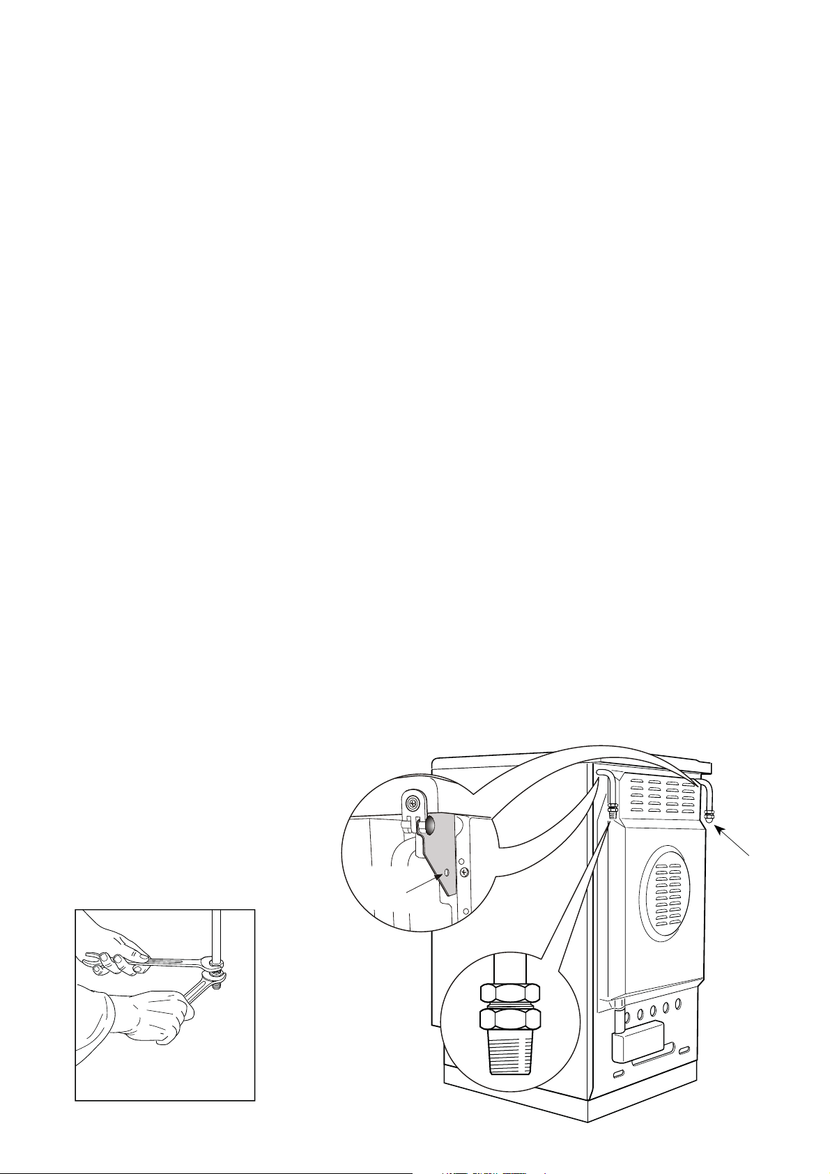
Installation with a flexible hose assembly
-
If this appliance has to be installed with a hose assembly, the installer shall refer to the network
operator or gas supplier for confirmation of the gas type, if in doubt.
- When used with a flexible hose, the connector on the wall should be between 450 mm to 500
mm from the floor and 200 mm to 300 mm from the left-hand side of the appliance as viewed
from the front. The hose connection on the appliance shall face downwards.
- It is important that the hose does not come in contact with the metal of the appliance and is
secured as per appropriate gas installation codes.
A chain 80% of the length of the flexible gas hose must be used to prevent stress being applied
to the hose. The chain should be attached securely to the product where shown, and on the wall.
- Flexible hose assemblies should be AS/NZS 1869 Class B or Class D certified.
The thread connection shall be Rp 1/2” (ISO 7-1) male.
- IMPORTANT WARNING: After connection the installer must check that the hose is not kinked,
subjected to abrasion or permanently deformed.
The installer must check also that the hose is not near (or in contact) with any hot surfaces.
- The hose assembly shall be as short as practicable and comply with relevant AS5601 / NZS5261
requirements.
Loading ...
Loading ...
Loading ...