Gather the required tools and parts before starting installation. Read and follow the instructions provided with any tools listed here.
Tools needed
Level
Drill
1¼" (3 cm) drill bit
¹⁄8 " (3 mm) drill bit
Pencil
Wire stripper or utility knife
Tape measure or ruler
Pliers
Caulking gun and weatherproof caulking compound
Vent clamps
Jigsaw or keyhole saw
Flat-blade screwdriver
Metal snips
Phillips screwdriver
Parts needed
Home power supply cable
1 - ½" (1.3 cm) UL listed or CSA approved strain relief
3 UL listed wire connectors
1 wall or roof cap
Metal vent system
Blower motor system - internal or external (see “Blower Motor System” in the “Accessories” section).
Parts supplied
Remove parts from packages. Check that all parts are included.
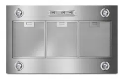
3 metal grease filters
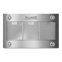
Hood liner with LED lamps installed.
1 - 10" (25.4 cm) square to 10" (25.4 cm) round duct transition with damper.
4 - 5 x 45 mm mounting screws
4 - 4.2 x 8 mm screws
T-20 TORX®† adapter
Location Requirements
IMPORTANT: Observe all governing codes and ordinances.
Have a qualified technician install the hood liner. It is the installer's responsibility to comply with installation clearances specified on the model/serial rating plate. The model/serial rating plate is located behind the left filter on the rear wall of the hood liner.
The hood liner location should be away from strong draft areas, such as windows, doors and strong heating vents.
Cabinet opening dimensions that are shown must be used. Given dimensions provide minimum clearance.
The hood liner must be surrounded by a custom built enclosure with hood support capable of supporting 75 lb (34 kg).
Grounded electrical outlet is required. See “Electrical Requirements” section.
All openings in ceiling and wall where canopy hood will be installed must be sealed.
For Mobile Home Installations
The installation of this range hood must conform to the Manufactured Home Construction Safety Standards, Title 24 CFR, Part 328 (formerly the Federal Standard for Mobile Home Construction and Safety, Title 24, HUD, Part 280) or when such standard is not applicable, the standard for Manufactured Home Installation 1982 (Manufactured Home Sites, Communities and Setups) ANSI A225.1/NFPA 501A, or latest edition, or with local codes.
Cabinet Dimensions
IMPORTANT: Minimum distance “X”: 24" (61 cm) from electric cooking surfaces. Minimum distance “X”: 30" (76.2 cm) from gas cooking surfaces. Suggested maximum distance “X”: 36" (91.4 cm).
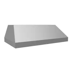
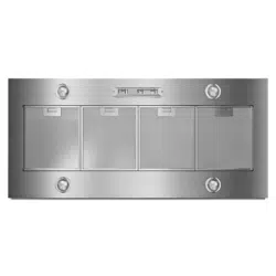
Product Dimensions
Venting Requirements
Vent system must terminate to the outdoors.
Do not terminate the vent system in an attic or other enclosed area.
Do not use 4" (10.2 cm) laundry-type wall caps.
Use metal vent only. Rigid metal vent is recommended. Plastic or metal foil vent is not recommended.
The length of vent system and number of elbows should be kept to a minimum to provide efficient performance.
For the most efficient and quiet operation:
Use no more than three 90° elbows.
Make sure there is a minimum of 24" (61.0 cm) of straight vent between the elbows if more than 1 elbow is used.
Do not install 2 elbows together.
Use clamps to seal all joints in the vent system.
Use caulking to seal exterior wall or roof opening around the cap.
The size of the vent should be uniform.
Cold weather installations
An additional back draft damper should be installed to minimize backward cold air flow and a thermal break should be installed to minimize conduction of outside temperatures as part of the vent system. The damper should be on the cold air side of the thermal break.
The break should be as close as possible to where the vent system enters the heated portion of the house.
Makeup air
Local building codes may require the use of makeup air systems when using ventilation systems greater than specified CFM of air movement. The specified CFM varies from locale to locale. Consult your HVAC professional for specific requirements in your area.
Venting Methods
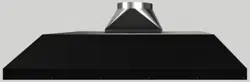
Typical Internal Blower Motor System Venting Installations A 10" (25.4 cm) round vent system is needed for installation (not included). The hood exhaust opening is 10" (25.4 cm) round.
NOTE: Flexible vent is not recommended. Flexible vent creates back pressure and air turbulence that greatly reduce performance.
Vent system can terminate either through the roof or wall. To vent through the wall, a 90° elbow is needed.
Typical In-line Blower Motor System Venting Installations
Calculating Vent System Length
To calculate the length of the system you need, add the equivalent feet (meters) for each vent piece used in the system.
The maximum equivalent vent lengths are: 10" (25.4 cm) round vents - 60 ft (18.3 m)
Example vent system
The following example falls within the maximum recommended vent length.
INSTALLATION INSTRUCTIONS
Prepare Location
It is recommended that the vent system be installed before hood is installed.
Before making cutouts, make sure there is proper clearance within the ceiling or wall for exhaust vent.
Hood liner is to be installed 24" (61.0 cm) minimum for electric cooking surfaces, 30" (76.2 cm) minimum for gas cooking surfaces, to a suggested maximum of 36" (91.4 cm) above the cooking surface.
Check that all installation parts have been removed from the shipping carton.
1. Disconnect power.
2. Determine which venting method to use: roof or wall exhaust.
3. Select a flat surface for assembling the range hood. Place covering over that surface.
4. Using 2 or more people, lift hood liner onto covered surface.
5. Remove the filters. See the “Range Hood Care” section.
Hood Liner Support Preparation
1. Mark the locations for the four ¹⁄₈" (3 mm) diameter holes on the hood support as shown.
2. Using a ¹⁄₈" (3 mm) drill bit, drill the 4 holes.
3. Mark the cutout for the rectangular clearance hole for the upper hood liner housing as shown.
4. Using a jigsaw or keyhole saw, cut out the rectangular clearance hole for the upper hood liner housing.
Complete Preparation
Determine and make all necessary cuts in the wall or roof for the vent system. Install the vent system before installing the range hood. See the “Venting Requirements” section.
Determine the location where the power supply cable will be run through the wall.
Drill a 1¹⁄₄" (3.2 cm) hole at this location.
Pull enough power supply cable through the wall to allow for easy connection to the terminal box.
Install the 10" (25.4 cm) square x 10" (25.4 cm) round vent transition with damper to top of the range hood liner using four 4.2 x 8 mm screws.
Remove terminal box cover and set aside.
Remove knockout from the top of the vent hood and install a UL listed or CSA approved ¹⁄₂" (1.3 cm) strain relief.
Place the range hood near its mounting position and run the power supply cable through the strain relief into terminal box (enough to make connection).
Tighten the strain relief screws.
NOTE: Your range hood requires you to purchase either an internal type or an in-line (external type) blower motor system.
For internal blower systems, there are blower motor mounting parts in the blower motor installation packet that must be added to the range hood prior to mounting the range hood to the wall. See the “Install Range Hood Internal Blower Motor” section and the instructions supplied with the blower motor.
Install Range Hood Liner
The hood liner attaches to the hood support using four mounting screws and washers.
NOTE: Hood support must be capable of supporting 75 lb (34 kg).
Using 2 or more people, lift the hood liner into place.
Install the hood liner using four 5 x 45 mm screws to the hood support and tighten securely
Install Hood Liner Internal Blower Motor
NOTE: Your hood liner requires you to purchase either an internal type or an in-line (external type) blower motor system. See “Blower Motor System” in the “Accessories” section.
The internal blower system can be mounted for top venting or rear venting. For top venting, the mounting bracket and spring clip that come with the blower system will mount to the top panel of the hood liner. For rear venting, the mounting bracket and spring clip that come with the blower system will mount to the rear panel of the hood liner.
Prepare the Internal Blower System
IMPORTANT: Perform steps 1-4 before mounting the hood liner.
Remove grease filters from hood liner. See the “Range Hood Care” section in the Use and Care Guide.
Install the motor support bracket using three 4.2 x 8 mm screws. Screw bracket to the inside top or back (alternate location on some models), toward the left side of the hood liner.
Install motor spring clip using two 4.2 x 8 mm screws. Screw spring clip to the inside top or back (alternate location on some models) of the hood liner at the proper location for the selected motor system. Slide the mounting tab of the spring clip through the slot in the panel and secure with the screws. Use the inside set of mounting holes for the single motor system. Use the outside set of mounting holes for the dual motor system.
Install the 6 mm nuts to the outside top or outside back (alternate location on some models) of the hood liner at the proper location for the selected motor system.
Two 6 mm nuts are required for the single motor system. Clip nuts into the small square notches located at the left and right end of the square vent opening.
Five 6 mm nuts are required for the dual motor system. Clip nuts into the small square notches, one located in the front of the square vent opening and the other four located at the left and right ends of the square vent opening
Mount hood liner. See the “Install Range Hood Liner” section.
Install Hood Liner Internal Blower Motor
1. Install the hood liner blower motor assembly inside the hood liner canopy with the wiring connection to the left for the single motor system and to the front or top for the dual motor system.
2. Slide the left mounting plate flange under the motor mounting bracket.
3. Run the power supply wires and connector from the range hood through the hole in the right end of the motor mounting plate.
4. Push the right end of the motor mounting plate up and snap it into the spring tab.
NOTE: The spring tab should be outside the slot in the mounting plate.
5. Align mounting holes in motor mounting plate with motor mounting clip nuts and install 6 x 16 mm screws and 6.4 mm lock washers (quantity 2 for single motor; quantity 5 for dual motor)
6. Attach power cord connector from the range hood to connector on wiring box.
7. Go to the “Make Electrical Power Supply Connection to Hood Liner” section.
Install Hood Liner In-Line (External Type) Blower Motor
NOTE: Your hood liner requires you to purchase either an internal type or an in-line (external type) blower motor system. See “Blower Motor System” in the “Accessories” section.
Prepare for Mounting the In-Line Blower System
The in-line blower system must be fastened to a secure structure of the roof, ceiling, wall, floor, or new or existing frame construction. The 4 holes on either the inlet (bottom) side or the outlet (top) side of the blower must be used to mount the in-line blower system to the structure.
NOTE: The mounting hole locations must span the studs. Additional stud framing may be required. Plywood may be used to span open areas between ceiling joists or roof rafters to aid installation. This structure must be strong enough to support the weight of the in-line blower system (50 lb [22.6 kg] min)
Prepare the In-line Blower System
Using two or more people, move the in-line blower motor system to the mounting location.
Remove the 10 screws from the front cover of the in-line blower motor housing and set them aside.
Remove the front cover of the in-line blower motor housing and set it aside. NOTE: To make the blower motor housing easier to mount, the blower motor assembly can be removed. If you do not want to remove the blower motor assembly, proceed to “Install In-line Blower System” in this section.
Disconnect the motor electrical plug from the blower motor assembly.
Remove the screws that secure the blower motor assembly to the in-line blower housing and set them aside.
Pull the spring clip to release the blower motor assembly. Remove the blower motor assembly from the housing and place it on a covered surface.
Install In-line Blower System
NOTE: The blower motor housing can be mounted using 4 holes from either the inlet side or the outlet side of the blower.
Position the in-line blower motor housing in its mounting location and mark the 4 mounting hole locations.
Drill 4 mounting pilot holes using a ³⁄₁₆" (5 mm) drill bit.
Attach the in-line blower motor housing to the mounting location with four 6 x 80 mm mounting screws and washers.
If it is removed, reinstall the blower motor assembly and secure it with the screws previously removed.
If it is removed, reattach the motor electrical plug to the connector on the blower motor assembly
Complete Preparation
1. Determine and make all necessary cuts for the vent system. IMPORTANT: When cutting or drilling into the ceiling or wall, do not damage electrical wiring or other hidden utilities.
2. Determine the location where the ¹⁄₂" (1.3 cm) wiring conduit will be routed through the ceiling or wall between the in-line blower and the hood liner.
3. Drill a 1¹⁄₄" (3.2 cm) hole at this location.
4. Locate the electrical terminal boxes in the in-line blower housing and hood liner. Remove the terminal box covers and set the covers and screws aside.
5. Remove the electrical knockout from the in-line blower housing and hood liner to prepare for the installation of the UL listed or CSA approved ¹⁄₂" (1.3 cm) wiring conduit and conduit connector.
6. With the hood liner mounted (see the “Install Hood Liner” section), run the ¹⁄₂" (1.3 cm) wiring conduit between the inline blower motor housing and the hood liner. Pull enough ¹⁄₂" (1.3 cm) wiring conduit to allow for easy connection to the terminal boxes in the in-line blower housing and hood liner.
7. Run the six 18 AWG wires through the ¹⁄₂" (1.3 cm) wiring conduit and conduit connectors and into the terminal boxes on the in-line blower housing and hood liner. Leave enough wire length in each terminal box to make the wiring connections.
8. Install the conduit connectors and conduit to the in-line blower housing and hood liner electrical terminal boxes.
9. Connect the vent system to the hood liner and in-line blower system and seal all joints with clamps.
Make Electrical Connections for In-Line Blower Motor System
Electrical Connection Inside In-line Blower System
1. Disconnect power.
2. Connect the wires from the wiring conduit to the wires from the motor electrical plug cable inside the in-line blower housing terminal box.
3. Use UL listed wire connectors and connect the black wires (C) together.
4. Use UL listed wire connectors and connect the white wires (D) together.
5. Use UL listed wire connectors and connect the red wires (E) together.
6. Use UL listed wire connectors and connect the blue wires (F) together.
7. Use UL listed wire connectors and connect the gray wires (G) together.
8. Connect the green (or yellow/green) ground wire to the green/yellow ground wire (H) in the terminal box using UL listed wire connectors.
9. Reinstall the in-line blower terminal box cover and screw.
10. Reinstall the front cover of the in-line blower housing and secure it with 10 mounting screws.
Electrical Connection Inside Hood Liner Between In-line Blower System and Hood Liner
With the hood liner mounted (see the “Install Hood Liner” section), locate the wiring cable connector inside the hood liner.
Connect the 6-wire connector assembly supplied with the in-line blower motor system to the mating cable connector from the hood liner.
Locate the terminal box inside the hood liner and install a ¹⁄₂" (1.3 cm) UL listed or CSA approved strain relief (see “Complete Preparation” in the “Prepare Location” section).
Run the wire ends from the 6-wire connector assembly through the ¹⁄₂" (1.3 cm) strain relief, leaving enough wire length to make the wiring connections. Tighten the strain relief screws.
Connect the wires from the 6-wire connector assembly to the wires from the wiring conduit inside the hood liner terminal box.
Connect the same color wires to each other (black to black, white to white, etc.) using UL listed wire connectors. NOTE: Connect the green (or green/yellow) ground wire from the wiring conduit to the green (or bare) ground wire from the home power supply using UL listed wire connectors (see the “Make Electrical Power Supply Connection to Hood Liner” section).
Go to the “Make Electrical Power Supply Connection to Hood Liner” section
Make Electrical Power Supply Connection to Hood Liner
Disconnect power.
Locate terminal box inside of the hood liner.
Use UL listed wire connectors and connect black wires (B) together.
Use UL listed wire connectors and connect white wires (A) together NOTE: When using an In-line blower motor system, the green (or green/yellow) ground wire in the conduit from the In-line blower motor system is to be connected with the green (or bare) wire of the home power supply cable and with the green/yellow wire (D) in the terminal box.
Connect green (or bare) ground wire from home power supply to the green/yellow ground wire (D) in terminal box using UL listed wire connectors.
Install terminal box cover.
Check that all light bulbs are secure in their sockets.
Reconnect power.
CompleteInstallationand Check Operation
Install grease filters. See the “Range Hood Care” section.
Check operation of the range hood blower and lights. See the “Range Hood Use” section.
If the range hood does not operate, check to see whether a circuit breaker has tripped or a household fuse has blown. Disconnect power supply and check that the wiring is correct.
NOTE: To get the most efficient use from your new hood liner, read the “Range Hood Use” section.
RANGE HOOD USE
The range hood is designed to remove smoke, cooking vapors and odors from the cooktop area. For best results, start the hood before cooking and allow it to operate several minutes after the cooking is complete to clear all smoke and odors from the kitchen.
The hood controls are located on the underside of the range hood.
Range Hood Controls
Operating the light
Move the light switch to the “1” position to turn range hood light to night light setting.
Move the light switch to the “2” position to turn range hood light to full light setting.
Move the light switch to the “Off” position to turn range hood light OFF.
Operating the fan
Move the fan switch to the “On” position to turn the fan ON. The fan will begin operating at the speed set on the fan speed switch.
Move the fan switch to the “Off” position to turn the fan OFF.
Auto On Fan
The range hood is equipped with a sensor to automatically turn on the fan when excessive heat is detected in the control area. When the fan switch is in the “Off” position, this sensor will turn the fan to high speed when necessary.
When the heat decreases, the fan will turn off. When the fan switch is in the “On” position, the heat sensor is not active and the range hood functions normally.
Adjusting the fan
The fan has 3 speed controls. Move the fan speed switch to “1” position for low speed, “2” position for medium speed, or “3” position for high speed.
Thermal Protector
The range hood is equipped with a thermal protector to avoid overheating conditions. If the range hood shuts off while in use, move fan slider switch to Off to turn off the range hood. Wait approximately 60 minutes, then move slider to On to restart the range hood.
RANGE HOOD CARE
Cleaning
IMPORTANT: Clean the hood and grease filters frequently according to the following instructions. Replace grease filters before operating hood.
Exterior Surfaces:
To avoid damage to the exterior surface, do not use steel wool or soap-filled scouring pads.
Always wipe dry to avoid water marks.
Cleaning Method:
Liquid detergent soap and water, or all-purpose cleanser
Wipe with damp soft cloth or nonabrasive sponge, then rinse with clean water and wipe dry
Metal Grease Filter:
1. Remove each filter by pulling the spring release handle and then pulling down the filter
2. Wash metal filters as needed in dishwasher or hot detergent solution.
3. Reinstall the filter by making sure the spring release handles are toward the front. Insert aluminum filter into upper track.
4. Push in spring release handle.
5. Push up on metal filter and release handle to latch into place.
6. Repeat steps 1-5 for the other filter.
Replacing a LED Lamp
Turn off the range hood and allow the LED lamp to cool. To avoid damage or decreasing the life of the new lamp, do not touch lamp with bare fingers. Replace lamp, using tissue or wearing cotton gloves to handle lamp. If new lamps do not operate, make sure the lamps are inserted correctly before calling service.
1. Disconnect power.
2. Push up on the lens and turn it counterclockwise.
3. Remove the lamp and replace it with a 120-volt, 6.5-watt maximum LED lamp with a GU10 base. Turn it clockwise to lock it into place.