Installation Requirements
Electrical Requirements
IMPORTANT
Observe all governing codes and ordinances.
It is the customer’s responsibility:
-
To contact a qualified electrical installer.
-
To assure that the electrical installation is adequate and in conformance with National Electrical Code, ANSI/NFPA 70 — latest edition*, or CSA Standards C22.1-94, Canadian Electrical Code, Part 1 and C22.2 No.0-M91 - latest edition** and all local codes and ordinances.
If codes permit and a separate ground wire is used, it is recommended that a qualified electrician determine that the ground path is adequate.
A copy of the above code standards can be obtained from:
National Fire Protection Association
1 Batterymarch Park
Quincy, MA 02169-7471
CSA International 8501
East Pleasant Valley Road
Cleveland, OH 44131-5575
Other Requirements
- A 120 volt, 60 Hz., AC only, 15-amp, fused electrical circuit is required.
- If the house has aluminum wiring, follow the procedure below:
1. Connect a section of solid copper wire to the pigtail leads.
2. Connect the aluminum wiring to the added section of copper wire using special connectors and/or tools designed and UL listed for joining copper to aluminum.
- Follow the electrical connector manufacturer’s recommended procedure. Aluminum/copper connections must conform with local codes and industry accepted wiring practices.
- Wire sizes and connections must conform with the rating of the appliance as specified on the model/serial rating plate. The model serial plate is located behind the filter on the rear wall of the range hood.
- Wire sizes must conform to the requirements of the National Electrical Code, ANSI/NFPA 70 (latest edition), or CSA Standards C22. 1-94, Canadian Electrical Code, Part 1 and C22.2 No. 0-M91 (latest edition) and all local codes and ordinances.
- A U.L.- or C.S.A.-listed conduit connector must be provided at each end of the power supply conduit (at the range hood and at the junction box).
Before Installing the Hood
- The Vent system must terminate outdoors.
- For the most efficient air flow exhaust, use a straight run or as few elbows as possible. CAUTION: Vent unit to outside of building, only.
- At least two people are necessary for installation.
- Fittings material are provided to secure the hood to most types of walls and ceilings. Consult a qualified installer to confirm that the fittings are suitable for your cabinets, walls, and ceiling.
- Do not use flexible ducting.
- COLD WEATHER installations should have an additional backdraft damper installed to minimize backward cold air flow and a nonmetallic thermal break to minimize conduction of outside temperatures as part of the ductwork. The damper should be on the cold air side of the thermal break. The break should be as close as possible to where the ducting enters the heated portion of the house
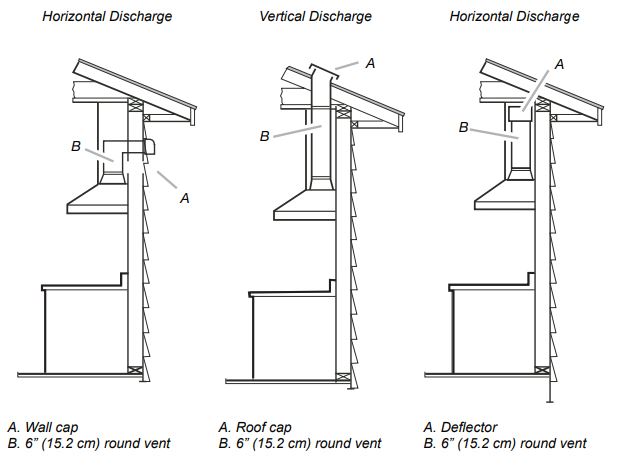
Venting Methods
Closely follow the instructions set out in this manual. Samsung is not responsible for any eventual inconveniences, damages or fires caused by not complying with the instructions in this manual.
Ducting version
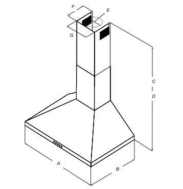
The hood is equipped with a 6” (15.2 cm) round transition for discharge of fumes to the outside.
Preparation
Do not cut a joist or stud unless absolutely necessary. If a joist or stud must be cut, then a supporting frame must be constructed. Fittings material are provided to secure the hood to most types of walls/ ceilings. However, a qualified technician must verify that the fittings are suitable for your cabinets, walls, and ceiling. Before making cutouts, make sure there is proper clearance within the ceiling or wall for the exhaust vent.
Ductless version (Recirculating)
For installations where cooking fumes and vapor cannot be discharged to the outside, attach a charcoal filter and the deflector on the duct cover support bracket. Fumes and vapors will be recycled through the top grille by a duct connected to the transition and the transition mounted on the deflector.
NOTE: For horizontal discharge only: purchase the Ductless Recirculating Kit. Minimum Duct Size: 6” Round Pipe.
CAUTION!
- For electric/induction cooktop & range installations: Mount the hood so the bottom is at least 24” (61cm) above the cooking surface.
- For gas cooktop & range installations: Mount the hood so the bottom is at least 27” (68.6 cm) above the cooking surface.
- For both, mount no higher than 36” (91.4 cm) above the cooking surface.
- Measure the mounting height from the surface of the range to the bottom of the hood.
WARNING:
This hood is intended for household use.
PLEASE READ THE INSTALLATION MANUAL FOR THE HOOD´S SPECIFIC APPLICATION. Check your ceiling height and the hood´s height before selecting your hood.
Tools and Parts
Removing the packaging
CAUTION! Remove the carton carefully. Wear gloves to protect against sharp edges.
WARNING: Remove the protective film covering the product before putting it into operation.
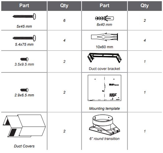
Parts supplied
- Hood assembly with blower and LED lamps already installed.
- Hardware bag with:
Tools/Materials required
- Level
- Drill with 1¼” (3.2 cm),1 ⁄8” (3.2 mm), and 1 ⁄16” (4.8 mm) drill bits
- Pencil
- Wire stripper or utility knife
- Tape measure or ruler
- Pliers
- Caulking gun and weatherproof caulking compound
- Jigsaw or keyhole saw
- Metal snips
- Screwdrivers:
• Phillips
• Flat - blade
Parts needed
- Home power supply cable
- ½” (12.7 mm) UL listed or CSA approved strain relief
- 3 UL listed wire connectors
- 1 wall or roof cap
- Metal vent system
Optional accessories and consumable parts
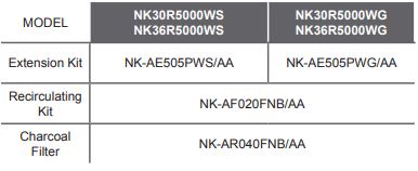
* Order the needed kit specifying your hood model.
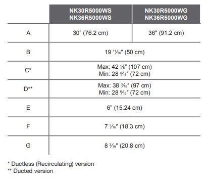
Dimensions and Clearances
Installation
Installation Instructions
We recommend that a qualified technician install the range hood. It is the installer’s responsibility to ensure the range hood complies with the installation clearances specifiations for the product.
- It is recommended that the vent system be installed before the hood is installed.
- Before making cutouts, make sure there is proper clearance within the ceiling or wall for the exhaust vent.
- Confirm that all installations parts have been removed from the shipping carton.
WARNING: To reduce the risk of fire, electric shock, or injury to persons, observe the following.
- Shut off power to the circuit you will be attaching the hood to at the circuit breaker panel or fuse box.
- Determine which venting method to use: roof, wall, or nonvented.
- Select a flat surface for assembling the range hood. Place a covering over that surface.
- Always have 2 or more persons lift or move the range hood.
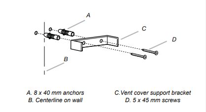
Mounting the duct cover bracket
- Determine and mark the centerline on the wall where the canopy hood will be installed. Shut off power at the circuit breaker panel or fuse box.
- Select a mounting height of no less than 24” (61 cm) above an electric cooking surface or 27” (68.6 cm cm) above a gas cooking surface.
- Tape the template in place, aligning the template center line and bottom with the hood center line and hood bottom line marked on the wall.
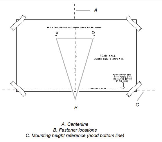
- Mark the centers of the fastener locations on the wall by pushing a pencil point through the template.
IMPORTANT: All screws must be installed into the wood studs or framing. If there is no wood to screw into, additional wall framing supports may be required.
- Remove the template.
- Drill 3 ⁄16″ (4.8 mm) pilot holes at all locations where screws are going to be installed into wood.
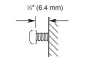
- Install the 2 - 5 x 45 mm mounting screws. Leave a 1 ⁄4″ (6.4 mm) gap between the wall and the back of the screw head to slide the range hood into place.
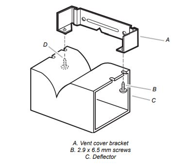
- Attach the vent cover bracket to the wall flush to the ceiling using 2 - 5 x 45mm screws.
Complete preparation
- Determine and make all necessary cuts in the wall for the vent system. Install the vent system before installing the hood. See “Venting Requirements” section.
- Determine the required height for the home power supply cable and drill a 1¼” (3.2 cm) hole at this location.
- Run the home power supply cable according to the National Electrical Code or CSA Standards and local codes and ordinances. There must be enough ½” conduit and wires from the fused disconnect (or circuit breaker) box to make the connection in the hood’s electrical terminal box.
NOTE: Do not turn on power until the installation is complete.
- Use caulk to seal all openings
Install the Range Hood
WARNING: USE TWO OR MORE PEOPLE TO MOVE AND INSTALL THE RANGE HOOD. FAILURE TO DO SO CAN RESULT IN BACK OR OTHER INJURY.
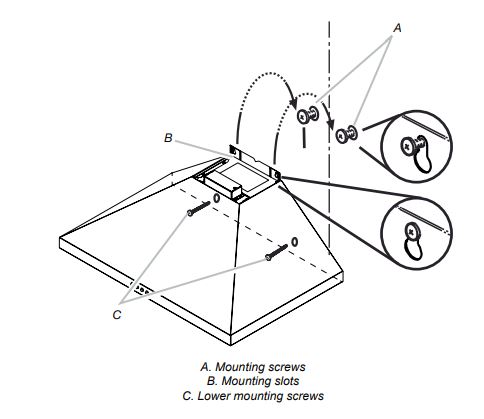
- Mark the lower mounting hole locations with a pencil .
- Uninstall the hood assembly, and drill 3 ⁄16”” (4.8 mm) pilot holes at the marked locations.
- Hang the range hood again on 2 the upper mounting screws.
- Level the range hood and tighten the upper mounting screws.
- Install 2 - 5 x 45 mm lower mounting screws and tighten. Use the optional wall anchors if needed.
Connect the vent system
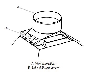
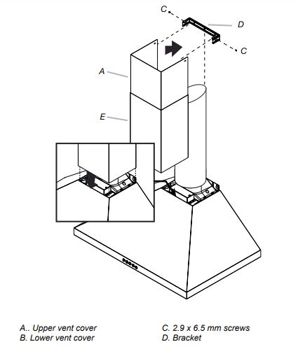
Install the transition on top of the hood (if removed for shipping) with 2-3.5x9.5 mm sheet metal screws.
For vented installations only
- Fit the vent system over the exhaust outlet.
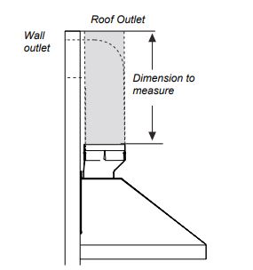
- Measure from the bottom of the air deflector to the bottom of the hood outlet. Cut the ductwork at the measured dimension.
- Seal the connection with clamps.
- Confirm that the back draft dampers work properly
Install Duct Covers
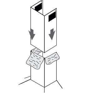
When using both upper and lower vent covers, push the lower cover down onto the hood and lift the upper cover to the ceiling, and then install with two mounting screws.
NOTE: For vented installations, the upper vent cover may be reversed to hide slots.
NOTE: To prevent scratches, lay paper or a kitchen towel over the edges of the lower flue duct to protect the surface.
Complete Installation
- For non-vented (recirculating) installations only, install charcoal filters over metal grease filter.
- Install metal filters. See the “Maintenance” section.
Electrical Connection
WARNING:
- Shut off power at the circuit breaker panel or fuse box before servicing. Replace all parts and panels before operating. Failure to do so can result in death or electrical shock.
WARNING:
Electrically ground the blower. Connect the ground wire to the green and yellow ground wire in the terminal box. Failure to do so can result in death or electrical shock.
- Shut off power at the circuit breaker panel or fuse box.
- Remove the terminal box cover.
- Remove the knockout in the terminal box cover and install a UL listed or CSA approved 1 ⁄ 2 ” strain relief.
- Run the home power supply cable through the strain relief, into the terminal box.
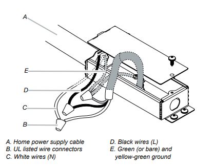
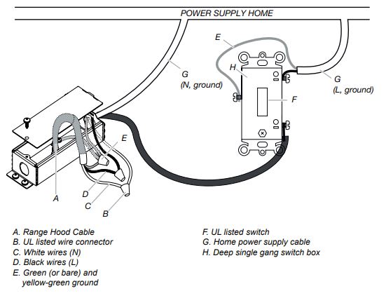
- Use UL listed wire connectors and connect the black wires (D) together.
- Use UL listed wire connectors and connect the white wires (C) together.
- Connect the green (or bare) ground wire from the home power supply to the yellow-green ground wire (E) in the terminal box using UL listed wire connectors.
- Tighten the strain relief screw.
- Install the terminal box cover.
- Turn on the power.
To get the most efficient use from your new range hood, read the “Maintenance” section. Keep your Use, Care, and installation Guide close to the range hood for easy reference.
Range Hood Use and Care
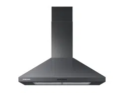
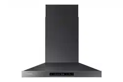
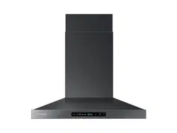
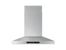
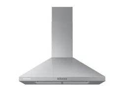
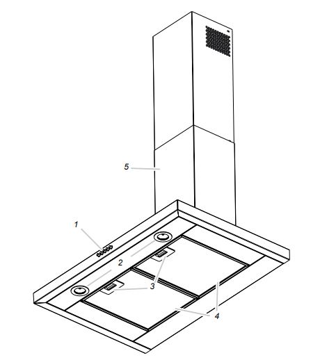
Description of the Hood
 |
|
- Blower and light controls
- LED lamps
- Grease filter handle
- Grease filters
- Duct covers
|
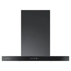
Control
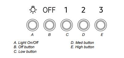
Operating the light
The Light On/Off button (A) controls both lights. Press once for On and again for Off.
Operating the blower
The Blower OFF button (B) turns the blower off.
The Blower Speed buttons (C,D,E) set the desired speed and control the sound level for quiet operation. The speed can be changed anytime during fan operation by pressing the desired blower speed button.
- To Turn the Blower On, press a Blower Speed button (C,D,E).
- To Turn the Blower off, press the Blower OFF Button (B).
Maintenance
Cleaning
- Do not spray cleaners directly onto the controls while cleaning the Hood. The hood should be cleaned regularly internally (at least as often as you clean the grease filters and externally.
- Clean using a cloth dampened with neutral liquid detergent.
- Do not use abrasive products.
- DO NOT USE ALCOHOL!
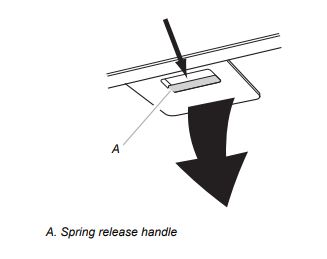
Grease Filter
Traps cooking grease particles. Th grease filter must be cleaned once a month using a mild detergent, either by hand or in a dishwasher, which must be set to a low temperature and a short cycle. When washed in a dishwasher, the grease filter may discolor slightly, but this does not affect its filtering capacity. To remove the grease filter, pull the spring release handle.
WARNING
Failure to carry out these basic cleaning recommendations for the hood and failure to clean the grease filter may cause fire risks. Therefore, we strongly recommend you follow these instructions. Samsung is not responsible for any damage to the motor or for any fire damage linked to inappropriate maintenance or failure to observe these cleaning and safety recommendations.
Replacing a LED lamp
The LED lights are replaceable by a service technician only. See the warranty for service contact information.
Accessories
For non-vented (recirculating) installation only
NOTE: To reduce the risk of fire or shock when the hood is used in recirculation mode, use only the conversion kit models listed below:
- Recirculating kit: NK-AF020FNB/AA
- Charcoal Filter Replacement kit: NK-AR040FNB/AA
To attach the recirculation kit, follow these steps:
- Assemble the air deflector with the duct cover bracket with 2 - assembly screws provided with the Recirculation Kit.
- Measure from the bottom of the air deflector to the bottom of the hood outlet.
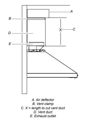
- Cut the duct to the measured size (X).
- Remove the air deflector.
- Slide the duct onto the bottom of the air deflector.
- Place the assembled air deflector and duct over the exhaust outlet from the hood.
- Re-attach the air deflector to the duct cover bracket with 2 assembly screws.
- Seal the connections with vent clamps
Charcoal filter
The charcoal filter is not washable. It should last up to 6 months with normal use. Replace with Charcoal Filter Replacement Kit.
To replace charcoal filter:
- Remove the metal grease filter from the range hood.
- Bend the spring clips away from the metal grease filter.
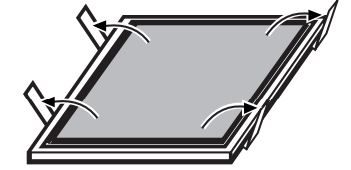
- Place the charcoal filter into the top side of metal filter.
- Insert the metal grease filter back into the range hood.
Range Hood for ADA Compliance
Range Hood Use and Care
Range hoods can be installed to comply with Sections 308 and 309 of ADA Guidelines, when used with appropriately mounted controls installed at 15” (38.1 cm) to 40” (101.6 cm) above the floor and control access does not require reaching over a cooking appliance.
The following range hoods NK30R5000WS, NK36R5000WS, NK30R5000WG, NK36R5000WG can work in an ADA Compliant situation when the range hood is wired to operate from a dedicated, standard electrical wall switch. To facilitate this application, share the information on the following pages with your electrician when preparing for the installation.
NOTE: All the models can be controlled by only one remote switch (The switch activates or deactivates the motor and the light of the hood).
WARNING! All electrical work must be done in accordance with local codes, ordinances, or the national electrical code as applicable. For safety, this product must be installed in a grounded switch box. The electrical wiring installation must be done by a qualified technician.
WARNING!
Electrical Shock Hazard. Turn off power at the circuit breaker panel or fuse box before servicing. Replace all parts and panels before operating.
Failure to do so can result in death or electrical shock.
WARNING!
To avoid fire or electrical shock, turn off power at the circuit breaker panel or fuse box. Confirm that the power is off before wiring.
1. MOUNT THE SWITCH BOX
Install a 3½” deepsingle gang switch box
2. ATTACH THE POWER CABLE
Clamp wiring to the switch box and unit using an appropriate clamp. Provide 6” leads inside the box and fan for easier wiring.
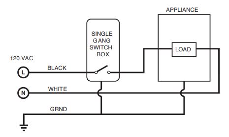
3. CONNECT THE WIRING
General instructions:
- Make sure both the switch box and the appliance are properly grounded.
- Make sure the ground wire is securely fastened to the control’s ground screw. Tighten the ground screw.
- Use proper wire nut sizes for the number and size of the wires.
- For push-in and screw terminals: Use min. #14 AWG solid copper wire only.
- Tighten the screw terminals.
- Make electrical connections following the appropriate diagram.
4. MOUNT THE CONTROL IN THE SWITCH BOX
Tuck wires into the switch box and fasten the control to the box using the attached screws.
5. ATTACH THE SWITCH PLATE
Fasten the switch plate to the control using the short screws from the parts bag.