Loading ...
Loading ...
Loading ...
30″ COOKTOP/DOWNDRAFT
UNITS JVB37 AND JVB94
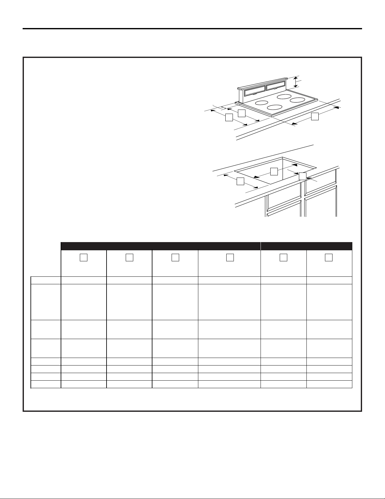
NOTE: Before you begin, measure and mark
Dimension 3 to ensure that adequate flat
countertop surface is available.
Identify the cutout illustration for the cooktop
model you are installing with this downdraft
vent system.
• Draw lines on the countertop to follow
as a cutting guide.
• Make sure sides of the opening are
parallel and rear and front cuts are exactly
perpendicular (right angle) to sides.
Planning Installation 30″ Electric and Gas Cooktops with Downdraft Vents Preparing Cutout
Overall Cooktop Surface Surface Depth Minimum Setback Combined Combined
Model No. Width Overall Depth with Downdraft* Cutout to Front Edge** Cutout Width Cutout Depth
JP326 30-1/4″ 21-1/4″ 23-3/8″ 2-1/2″ 28-1/2″ 22-3/8″
JP340
JP350
29-3/4″ 20-7/8″ 23″ 2-1/2″ 28-1/2″ 22-1/4″
JP930
JP931
JP938
JP939
JP350SC
JP930SC 29-7/8″ 21-1/2″ 23-5/8″ 2-1/2″ 28-1/2″ 22-3/8″
JP938SC
JGP328
JGP933 30″ 21″ 23-1/8″ 2-1/2″ 28-1/2″ 22-3/8″
JGP933S
JGP336 30″ 21″ 23-1/8″ 2-1/2″ 28-1/2″ 22-1/4″
JGP932 29-3/4″ 21″ 23-1/8″ 2-1/2″ 28-1/2″ 22-1/4″
JGP930S 30″ 21-1/4″ 23-3/8″ 2-1/2″ 28-1/2″ 22-1/4″
JGP932S 29-7/8″ 21-5/8″ 23-3/4″ 2-1/2″ 28-1/2″ 22-5/8″
**Includes 1/8″ gap between cooktop and vent trim
**Required to maintain UL or AGA approvals
654321
10
Installation Instructions
INSTALLING THE DOWNDRAFT VENT SYSTEM
2
1
⁄8″
8
1
⁄2″
1
2
3
4
5
6
Loading ...
Loading ...
Loading ...