Loading ...
Loading ...
Loading ...
Checkalignmentof valves after connecting the
cooktop to the gas supply to be sure the cooktop
manifold pipe has not been moved.
Disconnect this cooktop and its individual shutoff
valve from the gas supply piping system during any
pressure testing of that system at test pressures
greater than V2psig (3.5 kPa or 14" (35.6 cm) water
column).
Isolate the cooktop from the gas supply piping
system by closing its individual manual shutoff valve
during any pressure testing of the gas supply piping
system at test pressures equal to or less than V2psig
(3.5 kPa or 14" (35.6 cm) water column).
7. Connect Electricity to Gas
Cooktop
Electrical Requirements
120 volt, 60 Hertz, properly grounded branch circuit
protected by a 15 amp circuit breaker or time delay
fuse. Do not use an extension cord with this
cooktop.
IMPORTANT Please read carefully.
For personal safety, this appliance must be
properly grounded.
The power cord of this appliance is equipped with a
3-prong (grounding) plug which mates with a standard
3-prong grounding wall receptacle (see Figure 7) to
minimize the possibility of electric shock hazard from
the appliance.
The wall receptacle and circuit should be checked by
a qualified electrician to make sure the receptacle is
properly grounded.
Disconnect electrical supply cord from
wall receptacle before servicing cooktop.
8. Check Operation
Refer to the Use and Care Guide packaged with the
cooktop for operating instructions and for care and
cleaning of your cooktop.
Do not touch the burners. They may be hot enough to
cause burns.
.
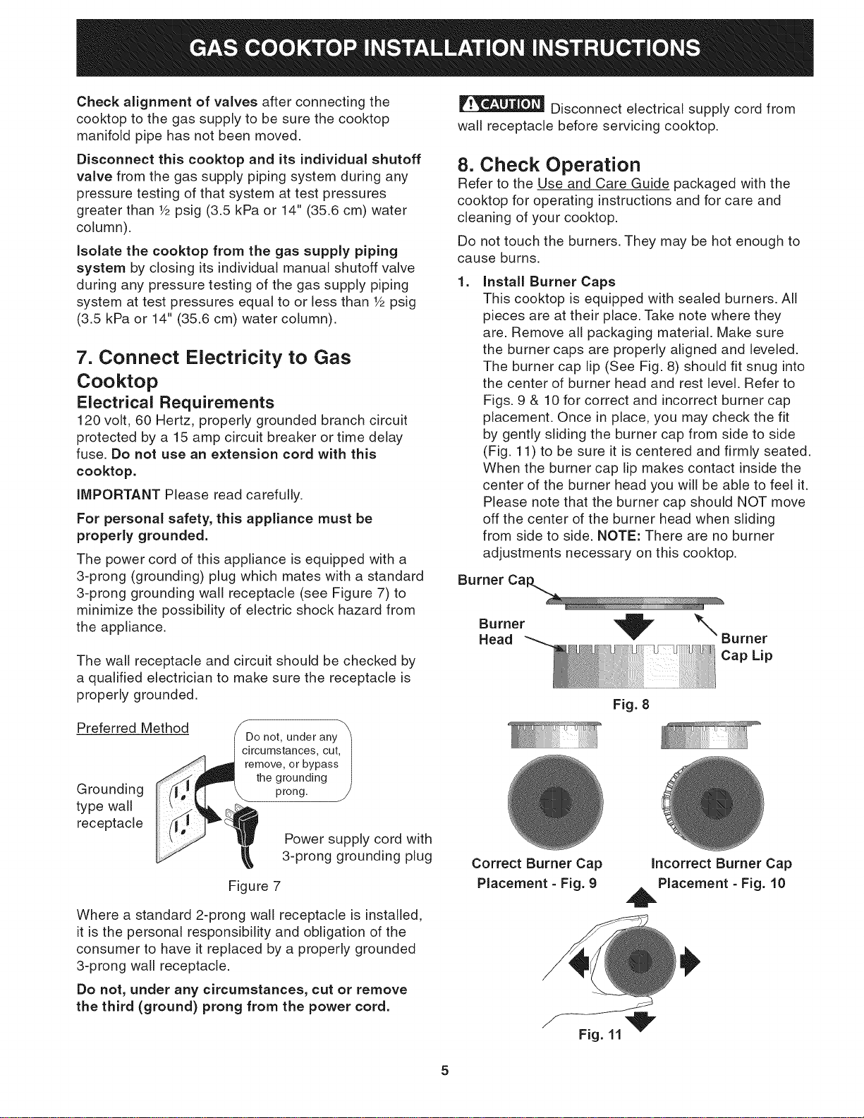
Install Burner Caps
This cooktop is equipped with sealed burners. All
pieces are at their place. Take note where they
are. Remove all packaging material. Make sure
the burner caps are properly aligned and leveled.
The burner cap lip (See Fig. 8) should fit snug into
the center of burner head and rest level. Refer to
Figs. 9 & 10 for correct and incorrect burner cap
placement. Once in place, you may check the fit
by gently sliding the burner cap from side to side
(Fig. 11) to be sure it is centered and firmly seated.
When the burner cap lip makes contact inside the
center of the burner head you will be able to feel it.
Please note that the burner cap should NOT move
off the center of the burner head when sliding
from side to side. NOTE: There are no burner
adjustments necessary on this cooktop.
Burner
Burner \Burner
Head
Cap Lip
Preferred Method
Grounding
type wall
receptacle
the grounding
prong.
Power supply cord with
3-prong grounding plug
Figure 7
Where a standard 2-prong wall receptacle is installed,
it is the personal responsibility and obligation of the
consumer to have it replaced by a properly grounded
3-prong wall receptacle.
Do not, under any circumstances, cut or remove
the third (ground) prong from the power cord.
Correct Burner Cap
Placement - Fig. 9
Fig. 8
Incorrect Burner Cap
Placement - Fig. 10
5
Loading ...
Loading ...
Loading ...