Loading ...
Loading ...
Loading ...
INSTALLATION
EN
TECHNICAL INFORMATION FOR THE INSTALLER
• Use protective gloves for handling, preparing and installing the product.
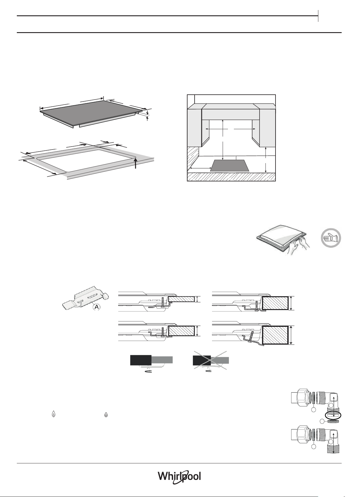
• This product can be embedded in a worktop 20 ÷ 40 mm thick.
• If there is no oven beneath the hob, insert a separator panel that has a surface at least equal to the opening in the work surface. This panel must
be positioned at a maximum distance of 150 mm below the upper surface of the work surface but, in no case less than 20 mm from the bottom
of the hob. In the case that you intend to install an oven beneath the hob, make sure that it is equipped with a cooling system. The manufacturer
declines all liability if another brand oven is installed beneath the hob.
DIMENSIONS AND DISTANCES TO BE MANTAINED
R = Min. 6.5 mm
Max. 8 mm
Min. 70 mm
730 mm
min. 480 mm
max. 492 mm
510 mm
0
+
2
560 mm
min. 38 mm
max. 42 mm
750mm
100mm
B
50mm
A
NOTE: Kitchen cabinets adjacent to the appliance and taller than the top of the hob must be at least 200 mm from the edge of the hob.
Hoods must be installed according to their relative installation instruction manuals and at a minimum distance of 650 mm from the hob
(see gure). Place the wall cabinets adjacent to the hood at a minimum height of 420 mm from the hob (see gure). If the hob is installed
beneath a wall cabinet, the latter must be situated at a minimum of 700 mm above the hob.
ASSEMBLY
After having cleaned the perimeter surface, apply the supplied gasket to the hob as shown in the
gure.
Position the hob in the worktop opening made respecting the dimensions indicated in the Instruction.
NOTE: the power supply cable must be long enough to permit its upward extraction.
To secure the hob, use the brackets (A) provided with it. Fit the brackets into the relevant bores shown by the arrow and fasten them by means of
their screws in accordance with the thickness of the worktop (see the following gures).
20
30
60
40
20 mm 40 mm
30 mm 60 mm
GAS CONNECTION
• Connect elbow (A)* or (B)* supplied with to the hob inlet main pipe and interpose the washer (C) supplied, in
compliance with EN 549.
* Use elbow (A) for United Kingdom and elbow (B) for all other destinations.
• After connection to the gas supply, check for leaks with soapy water. Light up the burners and turn the knobs from
max position to minimum position
to check ame stability.
C
B
C
C
A
Loading ...
Loading ...
Loading ...