Loading ...
Loading ...
Loading ...
Installation
Installation
English22
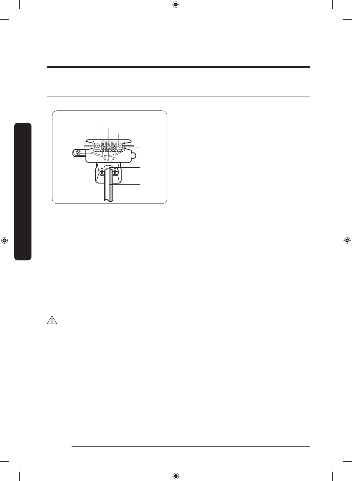
STEP 2 3-WIRE system connections
First, read through the “Electrical requirements” section, and then follow these steps.
1
2
3
Neutral
Earth
Live
1. Center silver-colored terminal block
screw.
2. Strain relief.
a. Loosen the terminal block screws.
b. Connect the earth wire (Green/
Yellow Striped wire) of the power
cord to the center terminal block
screw. Tighten screw.
c. Connect the neutral wire (Blue
wire) of the power cord to the
left terminal block screw. Tighten
screw.
d. Connect the live wire (Brown) of
the power cord to the right terminal
block screw. Tighten screw.
e. Tighten the strain relief screws.
f. Insert the tab of the terminal block
cover into the rear panel slot.
Secure the cover with a hold down
screw.
3. The power cable H05 VV-F (min. 1.9 m,
min. 2.5 mm²) must be of sufcient
length to be connected to the dryer.
WARNING
• The dryer is designed for a 3-wire system connection. The dryer frame is grounded to
the neutral conductor at the terminal block.
• Remove the terminal block cover plate. Insert the power cord through the hole
provided in the cabinet near the terminal block.
• A strain relief must be used. Do not loosen the nuts already installed on the terminal
block. Be sure they are tight. Use a 3/8” (1 cm) deep well socket.
DV6500K_DC68-03381E-01_EN.indd 22 11/1/2017 2:56:28 PM
Loading ...
Loading ...
Loading ...