Read through the following instructions before installing the dryer, and keep this manual for future reference.
WARNING
Certain internal parts are intentionally not grounded and may present a risk of electric shock only during servicing. Service Personnel - Do not contact the following parts while the appliance is energized: Control board and inlet valve.
Key installation requirements
A grounded electrical outlet.
A power cord for electric dryers (except in Canada).
Gas lines (for gas models) that must meet national and local regulations.
An exhaust system made of rigid metal or flexible stiff-walled metal exhaust ducting.
Location considerations
The dryer should be located where there is enough space at the front for loading the dryer. and enough space behind for the exhaust system. This dryer is factory-ready for the rear exhaust option. To exhaust out the bottom. right or the left. use the accessory exhaust kit. Instructions are included with the kit. Make sure the room in which the dryer Is located has enough fresh air. The dryer must be located where there are no air-flow obstructions. For gas dryers. adequate clearance must be maintained as noted on the data plate to ensure adequate air for combustion and the praper dryer operation.
The dryer must not be installed or stored in an area where it will be exposed to water and/or weather. The dryer area must be kept clear of combustible materials. gasoline. and other flammable vapors and liquids. A dryer produces combustible lint. The area around the dryer should be kept lint-free
Dimensions
Clearance requirement
This clearance requirement is applicable for dryers only.
NOTE
For washer's clearance requirement, see the washer's user manual.
If the washer and dryer have different clearance requirements, use the one with the larger value.
Alcove or closet installations
WARNING
The dryer must be exhausted to the outside to reduce the risk of fire when installed in an alcove or closet
No other fuel-burning appliance should be installed in the same closet as the dryer.
Place the dryer at least 18 in. (460 mm) above the floor for garage installation.
Minimum clearance for stable operation:
If both the washer and a dryer are installed in the same location, the front of the alcove or closet must have two unobstructed air openings for a combined minimum total area of 72 in.² (465 cm²).
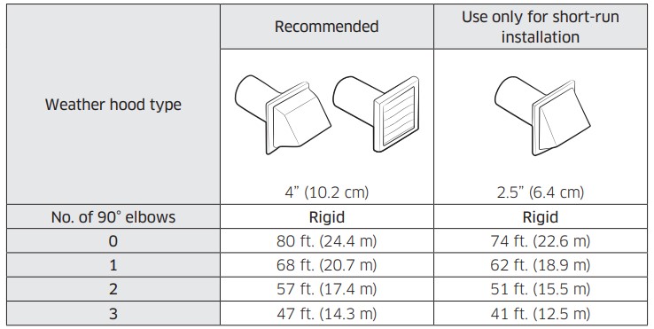
Ducting requirements
If you integrate the dryer’s vent system with an existing exhaust system, make sure:
The exhaust system meets all applicable local, state, and national regulations.
Not to use a flexible plastic duct.
To regularly check and clean all lint buildup from inside the existing ducts.
The duct is not kinked or crushed.
The exhaust hood damper opens and closes freely.
Manometer measurements
The static pressure in any exhaust system must not exceed 0.83 inches of water column or be less than 0. Note that these values are measured with the dryer running with a manometer presented to the exhaust duct that connects to the dryer. The dryer tumbler must be empty and lint filter clean.
Exhausting requirements
The dryer must not be exhausted into a chimney, a wall, a ceiling, an attic, a crawl space, or a concealed space of a building. Exhausting the dryer to the outside will prevent large amounts of lint and moisture from being blown into the room.
In the United States and Canada
All dryers must be exhausted to the outside.
The required exhaust duct is 4 inches (10.2 cm) in diameter.
See “Ducting requirements” in the “Installation” section for the maximum duct length and number of bends that can be used.
The total length of flexible metal duct must not exceed 7’ 10 1/2” (2.4 m).
Do not assemble the duct with screws or other fastener means that extend into the duct and catch lint.
For the United States only: Use only those foil-type flexible ducts, if any, specifically identified for use with the appliance by the manufacturer and that comply with the Outline for Clothes Dryer Transition Duct. Use Subject 2158A.
Outside the United States and Canada
Refer to the local codes.
Gas requirements
WARNING
Use only natural or LP (liquid propane) gases.
THE INSTALLATION MUST CONFORM WITH LOCAL CODES, OR IN THE ABSENCE OF LOCAL CODES, WITH THE NATIONAL FUEL GAS CODE ANSI/ Z223.1, LATEST REVISION (FOR THE UNITED STATES), OR WITH THE CAN / CGA-B149 INSTALLATION CODES (FOR CANADA).
Gas dryers are equipped with a burner vent for use with natural gas. If you plan to use your dryer with LP (liquid propane) gas, it must be converted for safe and proper performance by a qualified service technician. (LNG models only) You must check the burner of your model and use the proper LP Kit accordingly. To check the detail information of the burner, open the door and check the rating label location on the door frame. - 20,000 BTU: LPKIT-4/XAA (DC98- 04114A) - 22,000 BTU: LPKIT-3/XAA (DC99- 00792A)
A 1/2” (1.27 cm) gas supply line is recommended and must be reduced to connect to the 3/8” (1 cm) gas line on your dryer. The National Fuel Gas Code requires that an accessible, approved manual gas shut-off valve be installed within 6” of your dryer.
Gas dryers installed in residential garages must be raised 18 inches (46 cm) above the floor.
Additionally, a 1/8” (0.3 cm) N.P.T. (National Pipe Thread) plugged tapping, accessible for test gauge connection, must be installed immediately upstream of your dryer’s gas supply connection.
Your dryer must be disconnected from the gas supply pipe system during any pressure testing of the system.
Do not reuse old flexible metal gas lines. Flexible gas lines must be design certified by the American Gas Association (CGA in Canada).
NOTE
Your dryer uses an automatic ignition system to ignite the burner. There is no constant burning pilot.
Any pipe joint compound used must be resistant to the action of any liquefied petroleum gas.
As a courtesy, most local gas utilities will inspect a gas appliance installation.
Commonwealth of Massachusetts installation instructions
Your dryer must be installed by a licensed plumber or gas fitter. A “T” handle manual gas valve must be installed in the gas supply line to your dryer. If a flexible gas connector is used to install your dryer, the connector can be no longer than 3’ (36”).
WARNING
Gas leaks may occur in your system, creating a dangerous situation.
Gas leaks may not be detected by smell alone.
Gas suppliers recommend you purchase and install a UL-approved gas detector.
Install and use in accordance with the manufacturer’s instructions.
Electrical requirements
The wiring diagram is located on the plate under the control panel or rear frame.
WARNING
Improperly connecting the equipment grounding conductor can result in a risk of electric shock. Check with a qualified electrician or serviceman if you are in doubt as to whether your dryer is properly grounded. Do not modify the plug provided with your dryer – if it doesn’t fit the outlet, have a proper outlet installed by a qualified electrician.
To prevent unnecessary risk of fire, electrical shock, or personal injury, all wiring and grounding must be done in accordance with local codes, or in the absence of local codes, in accordance with the National Electrical Code, ANSI/ NFPA No. 70-Latest Revision (for the U.S.) or the Canadian Electrical Code CSA C22.1 – Latest Revisions and local codes and ordinances. It is your responsibility to provide adequate electrical service for your dryer.
All gas installations must be done in accordance with the national Fuel Code ANSI/Z2231 – Latest Revision (for the U.S.) or CAN/CGA – B149 Installation Codes – Latest Revision (for Canada) and local codes and ordinances.
Grounding
This dryer must be grounded. In the event of malfunction or breakdown, the ground will reduce the risk of electrical shock by providing a path of least resistance for the electrical current.
Gas models
WARNING
Your dryer has a cord with an equipment-grounding conductor and a grounding plug. The plug must be plugged into an appropriate outlet that is properly installed and grounded in accordance with all local codes and ordinances.
Do not modify the plug provided with your dryer – if it doesn’t fit the outlet, have a proper outlet installed by a qualified electrician.
Do not connect the ground wire to plastic plumbing lines, gas lines, or hot water pipes.
Electric models
WARNING
Your dryer has an optional cord with an equipment-grounding conductor and a grounding plug. This cord is sold separately.
The plug must be plugged into an appropriate outlet that is properly installed and grounded in accordance with all local codes and ordinances.
Do not modify the plug provided with your dryer – if it doesn’t fit the outlet, have a proper outlet installed by a qualified electrician.
If a power cord is not used and the electric dryer is to be permanently wired, the dryer must be connected to a permanently grounded metal wiring system, or an equipment grounding conductor must be run with the circuit conductors and connected to the equipment grounding terminal or lead on the dryer.
Electrical connections
Before operating or testing, follow all grounding instructions in the “Grounding” section. An individual branch (or separate) circuit serving only your dryer is recommended.
Do not use an extension cord.
Gas models – U.S. and Canada
A 120 volt, 60 Hz AC approved electrical service with a 15-ampere fuse or circuit breaker is required.
Electric models – U.S. only
Most U.S. dryers require a 120 / 240 volt, 60 Hz AC approved electrical service. Some require 120 / 208 volt, 60 Hz approved electrical service. The electric service requirements can be found on the data label located behind the door. A 30-ampere fuse or circuit breaker on both sides of the line is required.
If a power cord is used, the cord should be plugged into a 30-ampere receptacle.
The power cord is not provided with U.S. electric model dryers. This cord is sold separately
Installation
This dryer must be installed by a qualified technician. The installer is responsible for connecting the dryer to the main power while observing the relevant safety regulations of your area.
What’s included
Make sure all the parts are included in the product package. If you have a problem with the dryer or the parts, contact a local Samsung customer center or the retailer.
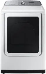
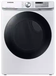
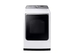
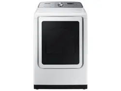
01 Worktop 04 Door
02 Control panel
05 Exhaust duct
03 Lint filter
Step-by-step installation
Make sure you have a qualified technician install the dryer. Step by step installation instructions start below.
Do not remove the protective film on the door before completing the product installation. If you remove the protective film before the installation is complete, the door may get scratched or damaged during installation.
Make sure the installation location allows enough space for the dryer door to be fully open
STEP 1 Install the exhaust system
Select a location and move the dryer to the site. For easy access, we recommend you install the dryer in the same location as your washer.
To change the door direction, see “Switching the door position”
Install the exhaust system as instructed in the “Exhaust ducting guide” section.
STEP 2 Connect the gas line (for gas models)
Before connecting the gas line, make sure you have read the “Gas requirements” section
Remove the protective cap from the gas pipe.
Apply an LPG (Liquefied Petroleum Gas)-safe compound or 1.5 wraps of Teflon tape to all threaded connections.
Connect the gas supply to the dryer. An additional fitting is required to connect the 3/4” (1.9 cm) female thread end of a flexible connector to the 3/8” (1 cm) male threaded end on the dryer. Tighten up the fitting over all threads
Turn on the gas supply, and check for any leaks using a soap solution. If a leak is found, tighten the connections and try again. Do not use an open flame to check for gas leaks.
STEP 3 Connect the electrical wiring (for electric models)
Before connecting the electrical wiring, make sure you have read the “Electrical requirements” section
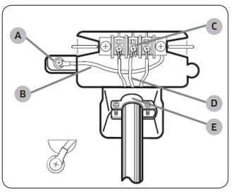
3-wire system
A. External ground connector
B. Neutral grounding wire (white)
C. Center silver-colored terminal block screw
D. Neutral wire (white or center wire)
E. 3/4” (1.9 cm) UL-listed strain relief
Loosen or remove the center terminal block.
Connect the neutral wire (white or center wire) of the power cable to the center, silver-colored terminal screw of the terminal block. Tighten the screws.
Connect the other wires to outer terminal block screws. Tighten the screws.
Tighten the strain relief screws.
Insert the terminal block cover into the rear panel of the dryer. Then, secure the cover with a hold-down screw.
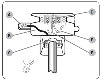
4-wire system
A. External ground connector
B. Green or bare copper wire of power cord
C. 3/4” (1.9 cm) UL-listed strain relief
D. Center silver-colored terminal block screw
E. Neutral grounding wire (white)
F. Neutral wire (white or center wire)
Remove the external ground connector’s screw and connect the ground wire (green or unwrapped) of the power cable to the screw.
Loosen or remove the screws from the center terminal block.
Connect the neutral wire (white or center wire) and ground wire (white) to the center screw of the terminal block. Tighten the screw.
Connect the other wires to the outer terminal block screws. Tighten the screws.
Tighten the strain relief screws.
Insert the tab of the terminal block cover into the rear slot of the dryer. Secure the cover with a hold-down screw.
STEP 4 Connect the water hose
The dryer must be connected to a cold water tap using the provided water hoses.
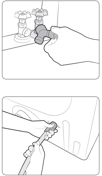
Close the cold water tap. If you have a washer’s cold water hose attached to the cold water tap, unscrew and remove the hose. Then, connect the female end of the Y-connector to the cold water tap.
Connect the straight end of the water hose to the Y-connector. Tighten the hose coupling by hand.
Using pliers, tighten the coupling an additional two-thirds turn. Do not overtighten. You can damage the coupling.
Connect the angled end of the water hose to the filling valve at the bottom rear of the dryer. Turn the coupling by hand until it is tight.
Using pliers, tighten the coupling an additional two-thirds turn. Do not overtighten. You can damage the coupling.
If you detached the cold water hose from your washer, attach the hose to the open end of the Y-connector, tighten the coupling by hand until it is tight, and then, using a pliers, tighten an additional two-thirds turn.
Open the cold water tap, and then check for any leaks.
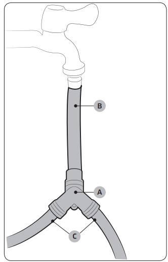
Using the short hose as an extension
Close the cold water tap. If you have a washer’s cold water hose attached to the cold water tap, unscrew and remove the hose. Then, connect the short hose (B) to the cold water tap. Turn the coupling by hand until it is tight.
Using pliers, tighten the coupling an additional two-thirds turn. Do not overtighten. You can damage the coupling.
Connect the Y-connector (A) to the brass male end of the short hose. Turn the coupling by hand until it is tight.
Using pliers, tighten the coupling an additional two-thirds turn. Do not overtighten. You can damage the coupling.
Connect the angled end of the water hoses (C) to the filling valve at the bottom rear of the dryer. Turn the coupling by hand until it is tight.
Using pliers, tighten the coupling an additional two-thirds turn. Do not overtighten. You can damage the coupling.
If you detached the cold water hose from your washer, attach the hose to the free end of the Y-connector, tighten the coupling by hand until it is tight, and then, using a pliers, tighten an additional two-thirds turn.
Open the cold water tap, and then check for any leaks.
STEP 5 Level the dryer
To ensure optimal performance, the dryer must be level.
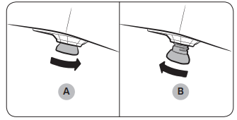
Using a level (A), check if the dryer is level side to side and then front to back. If the dryer is not level, turn the leveling feet (B) clockwise to lower the dryer or counterclockwise to raise the dryer.
NOTE
To set the dryer to the same height as your washer, fully retract (A) the leveling feet by turning them counterclockwise, then loosen (B) the feet by turning them clockwise. Once the dryer is the same height as the washer, follow the directions above to level the dryer.
Adjust the leveling feet only as much as necessary to level the dryer. Extending the leveling feet more than necessary can cause the dryer to vibrate.
STEP 6 Power on (for gas models)
Make sure all gas connections, the exhaust line, and all wiring is connected correctly. Then, plug the power cord into a power source and check the dryer’s installation and operation using the final checklist in Step 7 below.
STEP 7 Final check
When installation is complete, confirm that:
The dryer is plugged into an electrical outlet and grounded properly.
The exhaust ductwork is connected, and the joints are taped.
You have used rigid or stiff-walled flexible metal duct material, not plastic flexible duct.
The dryer is level and is sitting firmly on the floor.
The dryer starts, runs, heats, and shuts off properly.
The gas is supplied properly with no leaks (For gas models only).
Operations
Control panel
01. Cycle Selector
Turn the Cycle Selector to select a desired cycle. When a cycle is selected, the cycle indicator lights up.
Steam Cycles (DVE(G)50R5400* models only): The dryer sprays water into the drum to deodorize clothes and reduce static electricity and wrinkles.
Manual Dry: The drying time is fixed.
02. Digital Graphic Display
Displays all cycle information, including the cycle time, information code, and operating status.
03. Dryness
Press to select a dry level. You can select from 5 different options (Less to More). Please refer to following recommendations to select the appropriate dryness.
For larger or bulkier loads, select More for complete dryness.
For items that needs to lay flat or hang to dry, use Less to partially dry items.
04. Temp.
Press to change the temperature of the current cycle. You can select from 5 different options (Low to High). Please select the appropriate temperature depending on the items in the load.
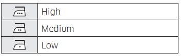
High: For sturdy cottons or those labeled Tumble Dry.
Medium: For permanent press, synthetics, lightweight cottons, or items labeled Tumble Dry Medium.
Low: For heat sensitive items labeled Tumble Dry Low or Tumble Dry Warm. Provides the lowest heated drying temperature possible
05. Time
Press to adjust the drying time for the Manual Dry cycles. This is not available with the Sensor Dry cycles because the dryer determines the drying time by sensing the current moisture level of the load.
06. Wrinkle Prevent
Wrinkle Prevent provides approximately 180 minutes of intermittent tumbling in unheated air at the end of the cycle to reduce wrinkling. Press Wrinkle Prevent to activate this feature. The load is dry, and can be removed at any time during the Wrinkle Prevent cycle
07. Eco Dry
This function is available with NORMAL and TIME DRY.
With the Eco Dry activated, drying takes a longer time but the power consumption is reduced.
The drying time can be extended by up to 3 times depending on the temperature and load. The Eco Dry function is enabled by default.
08. Damp Alert
This alert is available for all Sensor Dry cycles except for SANITIZE and ACTIVEWEAR. Available dry levels are Normal, More, and Extra.
If a load contains mixed fabrics, the Damp Alert indicator blinks when average dryness of the items in the load is 80 % dry. This lets you take items that you don’t want fully dried or that dry quickly out of the dryer early while letting others continue to dry.
09. Drum Light
Press to turn the interior lamp on or off. The lamp stays lit for 2 minutes after it has turned on, regardless of whether the power is on or off or the door is open or closed, and then turns off automatically.
10. Adjust Time
You can change the set time for the selected cycle. This is available only with TIME DRY, QUICK DRY, and AIR FLUFF. To change the cycle time, press Adjust Time ∧ or Adjust Time ∨ until the desired time is displayed.
After connecting the Tumble Dryer to your home network using the SmartThings app, you can control or monitor the dryer remotely. When started, the Smart Control (Smart Monitor) indicator blinks. The dryer enters waiting mode and waits for remote commands.
12. Power
Press to turn on/turn off the dryer.
13. Start/Pause (Hold to Start)
Press and hold to start operation or press to stop operation.
Icon description
Simple steps to start
Press Power to turn the dryer on.
Turn the Cycle Selector to select a cycle.
Change the cycle settings (Dryness, Temp., and Time) as necessary.
Select desired options as necessary. 5. Press and hold Start/Pause (Hold to Start).
To change the cycle during operation
Press Start/Pause (Hold to Start) to stop operation.
Select a different cycle, and repeat steps 2-4 above if necessary.
Press and hold Start/Pause (Hold to Start) again to start the new cycle.
Maintenance
Keep the dryer clean for best performance and to lengthen its life cycle.
WARNING
Certain internal parts are intentionally not grounded and may present a risk of electric shock only during servicing.
Service Personnel - Do not contact the following parts while the appliance is energized: Control board and inlet valve.
Cleaning
Control panel
Clean with a soft, damp cloth. Do not use abrasive substances.
Do not spray liquid cleaning agents directly onto the dryer display.
Some laundry pre-treatment soil and stain removers may damage the control panel.
When using liquid cleaning agents, apply them to the cleaning cloth. Do not apply them directly to the dryer. Wipe up any spills or overspray immediately.
Drum
Remove any stains from the drum with an all-purpose cleaner.
Tumble old towels or rags to remove any remaining stains or cleaning substances. Stains may be still visible but will not affect subsequent loads.
Powder coated drum
To clean the powder coated drum, use a damp cloth with a mild, non-abrasive cleaner suitable for easily marred surfaces.
Remove cleaner residue and dry with a clean cloth.
Dryer exterior
Clean with a soft, damp cloth. Do not use abrasive substances.
Protect the surface from sharp objects.
Do not place any heavy or sharp objects or a detergent container on the dryer. They can scratch or damage the top cover of the dryer.
The dryer has a high-gloss finish on the entire surface. Be careful not to scratch or damage the surface.
Exhaust system
Check and clean the exhaust system on a regular basis to maintain optimum performance.
The external exhaust hood must be cleaned frequently to ensure proper air flow.
Troubleshooting
Checkpoints
If the dryer operates abnormally, first check the list of problems in the table below and try the suggested actions.
Problem
Action
Does not run.
Make sure the door is latched shut.
Make sure the power cord is plugged into a live electrical outlet.
Check your home’s circuit breakers or fuses.
Press or tap Start/Pause (Hold to Start) again if the door was opened during a cycle.
Clean the lint filter.
Does not heat.
Check your home’s circuit breakers or fuses.
Some cycles do not require heat. Check the selected cycle again.
For a gas dryer, make sure the gas supply is on.
Clean the lint filter and exhaust duct.
The dryer may have moved into the cool-down phase of the cycle.
Turn off the Eco Dry option for the NORMAL or TIME DRY cycles. When the Eco Dry option is on, the dryer performs an air dry process in the beginning of the cycle to reduce energy consumption. The air dry process does not use heated air, so you may feel that the dryer is not being heated, but this is normal.
Does not dry.
Check all of the above, plus...
Make sure the exhaust hood outside your home can open and close freely.
Check the exhaust system for lint buildup. Ducting should be inspected and cleaned annually.
Use a 4” rigid metal exhaust duct.
Do not overload. 1 wash load = 1 dryer load.
Dry heavy items and light weight items separately.
Large, bulky items, such as blankets or comforters, may require repositioning to ensure even drying.
Make sure that your washer is draining properly and extracting adequate water from the load.
The load may be too small to tumble properly. Add a few towels and restart the dryer.
The load may be too large to tumble properly. Remove some items and restart the dryer.
Clean the lint filter.
Is noisy
Check the load for objects such as coins, loose buttons, nails, etc. Remove promptly.
It is normal to hear the dryer gas valve or heating element cycle on and off during the drying cycle.
Make sure the dryer is leveled properly as outlined in the installation instructions.
It is normal for the dryer to hum due to the high velocity of air moving through the dryer drum, fan, or exhaust system.
Dries unevenly.
Seams, pockets, and other similarly heavy areas may not be completely dry when the rest of the load has reached the selected dryness level. This is normal. You can choose a higher dryness level or a cycle that involves a higher dryness level.
If one heavy item is dried with a light weight load, such as one towel with sheets, it is possible that the heavy item will not be completely dry when the rest of the load has reached the selected dryness level.
For the best drying results, dry heavy items and light weight items separately.
Has odors.
Household odors from paint, varnish, strong cleaners, etc. may enter the dryer with the surrounding room air. This is normal as the dryer draws the air from the room, heats it, pulls it through the tumbler, and exhausts it outside.
When these odors linger in the air, completely ventilate the room before using the dryer.
Use the REFRESH cycle. If odors persist, wash and dry the items again
Lint on clothes.
Make sure the lint filter is cleaned before every load. For clothes that naturally build up lint, clean the filter during the cycle.
Some fabrics are lint producers (for example, a fuzzy white cotton towel) and they must be dried separately from clothes that are lint trappers (for example, a pair of black linen pants).
Divide larger loads into smaller loads for drying.
Check pockets thoroughly before drying, then dry clothes.
Remove lint inside the drum before drying a load.
Items still wrinkled after Wrinkle Prevent (Wrinkle Away, Wrinkle Release).
Small loads of 1 to 4 items work best.
Load fewer items. Load similar-type items.
Take out the items immediately after drying is complete.
Water drips from the nozzle when the Steam cycles starts.
This is steam condensation. The dripping water will stop after a short time.
Sprayed water is not visible during Steam cycles.
Sprayed water is difficult to see when the door is closed.
Extended time.
Sensor Dry automatically senses the moisture in the load and shuts the dryer off when the selected dryness level is reached. The drying time can change according to the type and amount of laundry. See the cycle chart for reference.
If a problem persists, contact a local Samsung service center.
Information codes
If the dryer fails to operate, you may see an information code on the display panel. To determine what you should do, check the list of codes in the table below, and then try the suggested actions.
Code
Action
dC
Operating the dryer with the door open.
Make sure the door is properly closed.
Make sure laundry is not caught in the door.
FC
Invalid power source frequency.
Try restarting the cycle.
If this information code remains, contact a Samsung service center.
AC
Electronic control problem (Invalid Communication).
Contact a Samsung service center.
HC
High temperature heating check.
Clean the lint filter.
If this information code remains, contact a Samsung service center.
9C1
The electronic control needs to be checked.
Check if power is supplied properly.
If the information code remains, contact a Samsung service center.
tC
The Thermistor1 resistance is very low or high.
Check for a clogged lint screen.
Check if the vent system is restricted.
If this information code remains, contact a Samsung service center.
tC5
The Thermistor2 resistance is very low or high.
Check for a clogged lint screen.
Check if the vent system is restricted.
If this information code remains, contact a Samsung service center.
dF
Incorrect door switch.
Contact a Samsung service center.
If any information code keeps appearing on the display, contact a Samsung service center.
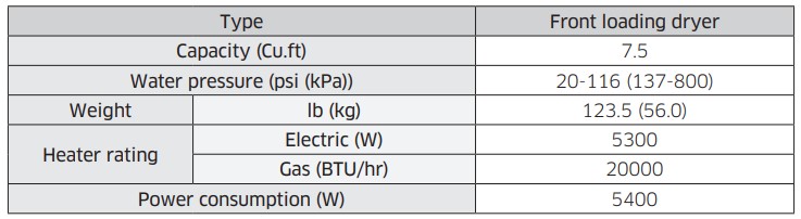
Specifications
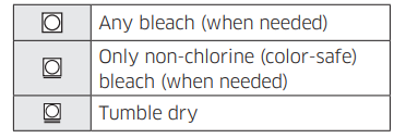
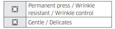
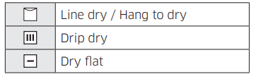
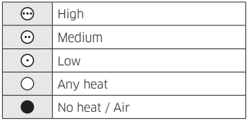
Fabric care chart
The following symbols provide garment care direction. The clothing care labels include symbols for drying, bleaching, drying and ironing, or dry cleaning when necessary. The use of symbols ensures consistency among garment manufacturers of domestic and imported items. Follow care label directions to optimize garment life and reduce laundering problems.
Wash cycle
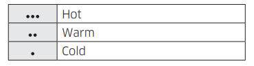
Water temperature
NOTE
The Water Temperature table lists appropriate wash water temperatures for various items. The temperature range is 106-126 °F (41-52 °C) for Hot, 84-106 °F (29-41 °C) for Warm, and 61-84 °F (16- 29 °C) for Cold. (Wash water temperature must be a minimum of 61 °F (16 °C) for detergent activation and effective cleaning.)
Bleach
Normal
Special instructions
Heat setting
Iron dry or steam temperatures
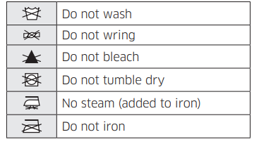
Warning symbols for laundering
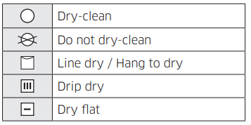
Dry-clean
Protecting the environment
This appliance is manufactured from recyclable materials. If you decide to dispose of this appliance, please observe local waste disposal regulations. Cut off the power cord so that the appliance cannot be connected to a power source. Remove the door so that animals and small children cannot get trapped inside the appliance.
 WARNING
 NOTE
NOTE
 WARNING
 NOTE
NOTE WARNING
 WARNING
 WARNING
 WARNING

 NOTE
NOTE

 WARNING
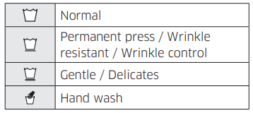
 NOTE
NOTE