Loading ...
Loading ...
Loading ...
16
ELECTRICAL CONNECTION
• The installation of this appliance and the connection to the electrical network should be
entrusted only to an electrician following the normal regulations.
• Protection against the parts under tension must be ensured after the building-in.
• The information on connections necessary are on the stickers. Place them on the hob
casing near the connection box.
• Connection to the mains must be made using an earthed plug, which must be accessible
after installation, or via an omnipolar circuit breaking device with a contact opening of at
least 3 mm.
• The electrical circuit must be separated from the network by adapted devices, for example:
circuit breakers, fuses or contactors.
• If the appliance is not fitted with an accessible plug, a disconnecting means must be
incorporated in the fixed installation, in accordance with the installation regulations.
• The inlet hose must be positioned so that it does not touch any of the hot parts of the hob
or oven.
• If the electrical supply is restricted, means of all-pole disconnection must be accessible
and incorporated in the fixed wiring in accordance with the wiring rules.
Caution!
This appliance must only be connected to a 230 V~ 50/60 Hz network.
Connect the earth wire.
Respect the connection diagram.
The connection box is located underneath at the back of the hob casing. To open the cover, use
a medium screwdriver. Place it in the slits and open the cover.
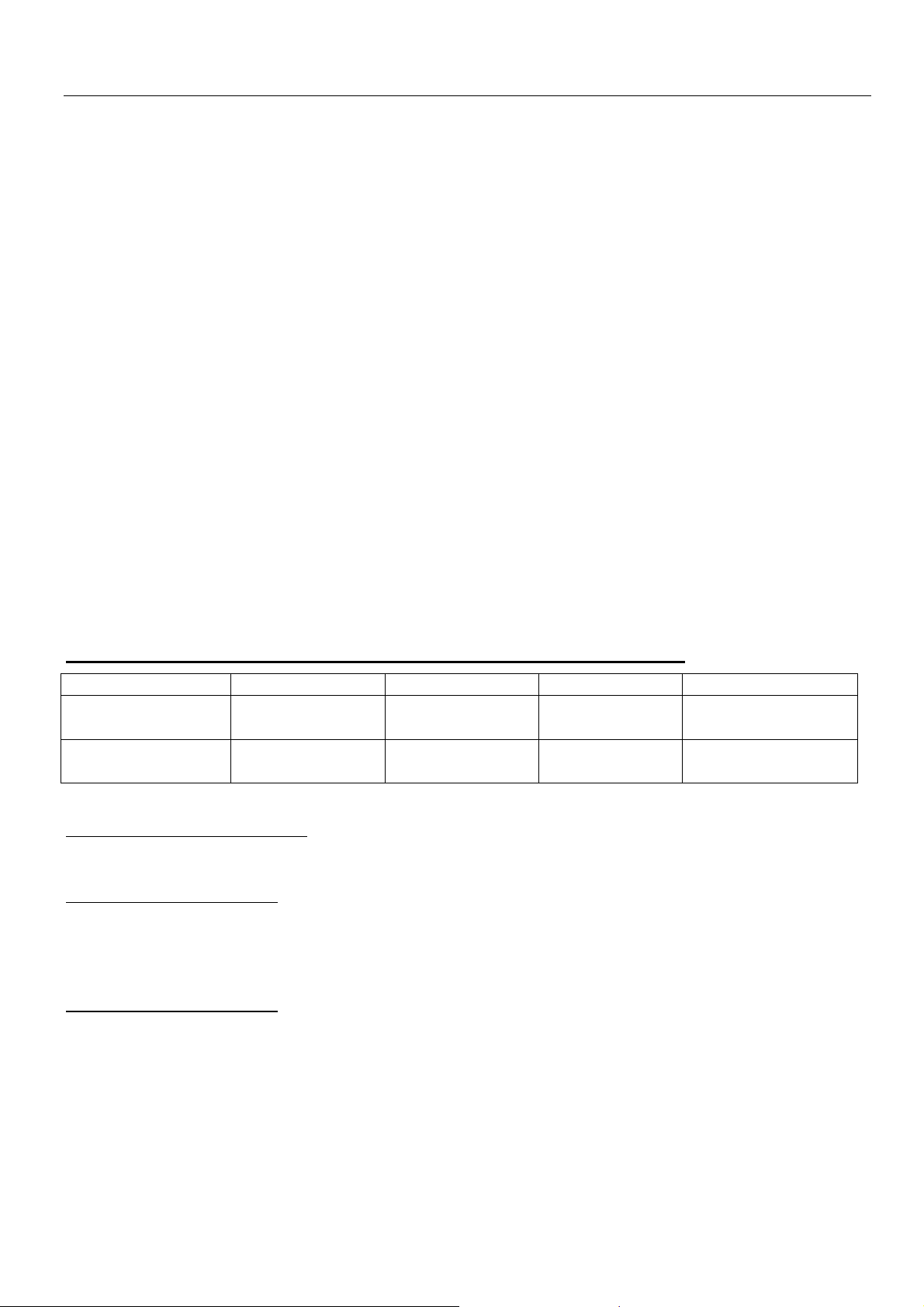
CONNECTION OF THE HOB FOR ILD914G5 , ILD604G5 AND ILD703G5
* calculated with the simultaneous factor following the standard EN 60 335-2-6/1990
Setting up the configurations:
For the various kinds of connection, use the brass bridges which are in the box next the terminal
Monophase 230V~1P+N
Put the 1
st
bridge between terminal 1 and 2, the 2
nd
between 4 and 5.
Attach the earth to the terminate “earth”, the neutral N to terminal 4 or 5, the Phase L to one of
the terminals 1 or 2.
Biphase 400V~2P+N
Put a bridge between terminal 4 and 5.
Attach the earth to the terminate “earth”, the neutral N to terminal 4 or 5, the Phase L1 to the
terminals 1 and the Phase L2 to the terminal 2.
Mains Connection Cable diameter Cable Protection calibre
230V~ 50/60Hz 1 Phase + N 3 x 2,5 mm²
H 05 VV - F
H 05 RR - F
25 A *
400V~ 50/60Hz 2 Phases + N 4 x 1.5 mm²
H 05 VV - F
H 05 RR - F
16 A *
Loading ...
Loading ...
Loading ...