
PE-DESIGN
PE-DESIGN
Version 5.0
Instruction Manual
IMPORTANT INFORMATION: REGULATIONS
Federal Communications Commissions (FCC) Declaration of Conformity
(For USA Only)
Responsible Party : Brother International Corporation
100 Somerset Corporate Boulevard
Bridgewater, NJ 08807-0911 USA
declares that the product
Product Name: Brother USB Writer
Model Number: PE-DESIGN
complies with Part 15 of the FCC Rules. Operation is subject to the following two conditions: (1) this
device may not cause harmful interference, and (2) this device must accept any interference received,
including interference that may cause undesired operation.
This equipment has been tested and found to comply with the limits for Class B digital device, pursu-
ant to Part 15 of the FCC Rules. These limits are designed to provide reasonable protection against
harmful interference in a residential installation. This equipment generates, uses, and can radiate
radio frequency energy and, if not installed and used in accordance with the instructions, may cause
harmful interference to radio communications. However, there is no guarantee that interference will
not occur in a particular installation. If this equipment does cause harmful interference to radio or tele-
vision reception, which can be determined by turning the equipment off and on, the user is encour-
aged to try to correct the interference by one or more of the following measures:
– Reorient or relocate the receiving antenna.
– Increase the separation between the equipment and receiver.
– Consult the dealer or an experienced radio/TV technician for help.
– Changes or modifications not expressly approved by the manufacturer or local sales distributor
could void the user’s authority to operate the equipment.
Canadian Department of Communications Compliance Statement
(For Canada Only)
This digital apparatus does not exceed the Class B limits for radio noise emission from digital
apparatus as set out in the interference-causing equipment standard entitled “Digital Apparatus”,
ICES-003 of the Department of Communications
Radio Interference
(Other than USA and Canada)
This machine complies with EN55022 (CISPR Publication 22) /Class B.

Congratulations on choosing our product!
Thank you very much for purchasing our product. To obtain the best performance from this unit and to
ensure safe and correct operation, please read this Instruction Manual carefully, and then keep it in a
safe place together with your warranty.
Please read before using this product
For designing beautiful embroidery patterns
• This system allows you to create a wide variety of embroidery patterns and supports a wider range of
sewing attribute settings (thread density, sewing pitch, etc.). However, the final result will depend on
your particular sewing machine model. We recommend that you make a trial sewing sample with
your sewing data before sewing on the final material.
For safe operation
• Avoid dropping a needle, a piece of wire or other metallic objects into the unit, or into the card slot.
• Do not store anything on the unit.
For a longer service life
• When storing the unit, avoid direct sunlight and high humidity locations. Do not store the unit close to
a heater, iron or other hot objects.
• Do not spill water or other liquids on the unit or cards.
• Do not drop or hit the unit.
For repairs or adjustments
• In the event malfunction occurs or adjustment is required, please consult your nearest service center.
Notice
This Instruction Manual does not explain how to use your computer under Windows. Please refer to the
Windows manuals.
Copyright acknowledgment
MS-DOS and Windows are registered trademarks of Microsoft Corp.
IBM is a registered trademark of International Business Machine Corporation.
Important
Using this unit for unauthorized copying of material from Embroidery Cards, newspapers and magazines
for commercial purpose is an infringement of copyright which is punishable by law.
Caution
The software included with this product is protected by copyright laws. This software can be used or cop-
ied only in accordance with the copyright laws.
“For additional product information and updates, visit our web site at:
www.brother.com”
“SAVE THESE INSTRUCTIONS”
“This product is intended for household use.”

New Features of Version 5.0
General
• USB card writer module . . . . . . . . . . . . . . . . . . . . . . . . . . . . . . . . . . . . . . . . . . . . . . . . . . . . . . . . . . .1
• Improved Thread Color Chart . . . . . . . . . . . . . . . . . . . . . . . . . . . . . . . . . . . . . . . . . . . . . . . . . .79, 144
• Automatic stitch direction recognition . . . . . . . . . . . . . . . . . . . . . . . . . . . . . . . . . . . . . . . . . . . . 98, 207
Design Center
• Most recent files added to Wizard . . . . . . . . . . . . . . . . . . . . . . . . . . . . . . . . . . . . . . . . . . . . . . . . . . . 84
Layout & Editing
• Imports data from embroidery cards. . . . . . . . . . . . . . . . . . . . . . . . . . . . . . . . . . . . . . . . . . . . . . . . 154
• Writes multiple data files to an original card . . . . . . . . . . . . . . . . . . . . . . . . . . . . . . . . . . . . . . . . . . 158
• Creates outline data from True Type font. . . . . . . . . . . . . . . . . . . . . . . . . . . . . . . . . . . . . . . . . . . . . 214
• Viewer makes changing the sewing order easier . . . . . . . . . . . . . . . . . . . . . . . . . . . . . . . . . . . . . . 210
• Creates stitch objects from shape object . . . . . . . . . . . . . . . . . . . . . . . . . . . . . . . . . . . . . . . . . . . . 203
• Optimizes entry points and exit points . . . . . . . . . . . . . . . . . . . . . . . . . . . . . . . . . . . . . . . . . . . . . . 218
• Simulates stitching . . . . . . . . . . . . . . . . . . . . . . . . . . . . . . . . . . . . . . . . . . . . . . . . . . . . . . . . . . . . . 221
• Imports and exports image data . . . . . . . . . . . . . . . . . . . . . . . . . . . . . . . . . . . . . . . . . . . 176, 178, 179
• Portrait Creator using built in files . . . . . . . . . . . . . . . . . . . . . . . . . . . . . . . . . . . . . . . . . . . . . . . . . . 177
• Wizard for creating stitch data from images . . . . . . . . . . . . . . . . . . . . . . . . . . . . . . . . . . . . . . . . . . 181
Automatic punching (also known as Auto-dizitizing) . . . . . . . . . . . . . . . . . . . . . . . . . . . . . . . . . . . . 182
Photo embroidery (2 types). . . . . . . . . . . . . . . . . . . . . . . . . . . . . . . . . . . . . . . . . . . . . . . . . . . 183, 190
Cross-stitching . . . . . . . . . . . . . . . . . . . . . . . . . . . . . . . . . . . . . . . . . . . . . . . . . . . . . . . . . . . . . . . . 195
• Allows you to edit entry points and exit points . . . . . . . . . . . . . . . . . . . . . . . . . . . . . . . . . . . . . . . . 124
• Curve block-type punching . . . . . . . . . . . . . . . . . . . . . . . . . . . . . . . . . . . . . . . . . . . . . . . . . . . . . . . 133
• Semi-automatic punching . . . . . . . . . . . . . . . . . . . . . . . . . . . . . . . . . . . . . . . . . . . . . . . . . . . . . . . . 133
• Measure Mode in manual punching . . . . . . . . . . . . . . . . . . . . . . . . . . . . . . . . . . . . . . . . . . . . . . . . 135
Others
• File Utility functions incorporated into Layout & Editing . . . . . . . . . . . . . . . . . . . . . . . . . . . . . . . . . 157
• Compatible with JPEG2000 (*.j2k) image files . . . . . . . . . . . . . . . . . . . . . . . . . . . . . . . . . . . . . . . . 176
• Photo Stitch from Design Center moved to Layout & Editing . . . . . . . . . . . . . . . . . . . . . . . . . . . . . 183
Contents Before Using Getting Started Design Center Layout & Editing
Programmable
Stitch Creator
Quick Reference Alphabetic Index
Before Using
■
Principal Parts............................................................ 1
■
Package Contents ..................................................... 1
■
Optional Supplies ...................................................... 1
■
Installing the Software .............................................. 2
System Requirements................................................. 2
Installation.................................................................... 2
Online Registration...................................................... 7
Uninstallation ............................................................... 7
Technical Support ....................................................... 7
■
Tips and Techniques for Creating Embroidery Pat-
terns ............................................................................. 8
Getting Started
Introduction.................................................................. 9
About this Chapter ...................................................... 9
• Layout & Editing .................................................... 9
• Design Center ..................................................... 10
• Programmable Stitch Creator............................. 10
■
Using the Auto Punch Function............................ 11
Starting Layout & Editing .......................................... 11
Opening an Image..................................................... 12
Editing the Image ...................................................... 13
Using the Wizard and Selecting the Auto Punch Func-
tion ............................................................................. 14
Automatically Extracting Pattern Outlines ................ 14
Automatically Creating an Embroidery Pattern........ 15
■
Using Design Center............................................... 16
Starting Design Center.............................................. 17
Opening an Image..................................................... 18
Converting to Line Image.......................................... 19
Editing Lines .............................................................. 20
Converting to Figure Handle Image ......................... 22
Moving to Sew Setting .............................................. 23
Setting Sewing Attributes.......................................... 23
• Setting the outlines.............................................. 23
• Setting the regions .............................................. 25
Previewing the Image ............................................... 28
Saving the File........................................................... 28
■
Using Layout & Editing........................................... 29
Starting Layout & Editing .......................................... 30
Importing Embroidery Patterns from Design Center 31
Zooming In and Out.................................................. 32
Moving the Embroidery Pattern ............................... 35
Adding an Oval ......................................................... 36
Adjusting the Size and Location of the Oval............ 37
• To change the size of the oval ........................... 37
• To center the oval on the pattern....................... 38
Adding Text............................................................... 38
Fitting the Text around the Oval............................... 40
Moving the Oval and Text ........................................ 41
• To move both patterns as a group..................... 41
• To move the text over the oval........................... 41
Adding a Circle for Drawing the Sun........................ 41
Selecting a Programmable Fill Stitch....................... 43
Adding Broken Lines for Drawing the Sun Rays..... 45
Changing the Sewing Order of Sun and Rays ........ 46
Adjusting the Rays.................................................... 46
Setting Hole Sewing ................................................. 47
Previewing the Sewing Image.................................. 48
Transferring the Data to a Card ............................... 49
Saving the File .......................................................... 49
■
Using Programmable Stitch Creator .................... 50
Starting Programmable Stitch Creator..................... 51
Opening a Programmable Stitch File....................... 52
Drawing Lines to Edit the Programmable Stitch...... 53
Saving the Edited Programmable Stitch.................. 54
Quitting Programmable Stitch Creator..................... 54
■
Creating data for the multi-position frame .......... 55
• Select the Design Page size .............................. 55
• Create the pattern............................................... 56
• Optimize Hoop Change...................................... 57
• Check the design................................................ 57
• Save the data...................................................... 58
• Write the data to an original card ....................... 58
Design Center
■
The Screen................................................................ 62
■
Using the Stage 2 Tool Box ................................... 63
Drawing and Erasing ................................................ 63
• Drawing............................................................... 63
• Erasing................................................................ 63
Zoom-in Mode .......................................................... 64
Fit Design Page to Window...................................... 64
Zoom-out Mode ........................................................ 64
■
Using the Stage 3 Tool Box ................................... 65
Selection Mode......................................................... 66
• Selecting patterns............................................... 66
Contents
Contents Before Using Getting Started Design Center Layout & Editing
Programmable
Stitch Creator
Quick Reference Alphabetic Index
• Moving patterns................................................... 66
• Scaling patterns................................................... 66
• Flipping a pattern horizontally or vertically ......... 67
• Rotating a pattern................................................ 67
Point Edit Mode......................................................... 68
• Moving points ...................................................... 68
• Inserting points .................................................... 68
• Deleting points..................................................... 68
Line Drawing Mode ................................................... 69
• Drawing a broken line ......................................... 69
Zoom-in Mode ........................................................... 69
Fit Design Page to Window ...................................... 70
Zoom-out Mode......................................................... 70
Enlarging Selected Outlines to the Screen Size ...... 70
■
Using the Stage 4 Tool Box ................................... 71
Region Setting Mode ................................................ 71
• Applying the sewing attributes to a region ......... 71
• Checking the sewing attributes of a region ........ 72
Line (all) Setting Mode .............................................. 73
• Applying the sewing attributes to an outline....... 73
• Checking the sewing attributes of an outline ..... 73
Line (part) Setting Mode ........................................... 74
• Applying the sewing attributes to a portion of the
outline ..................................................................74
• Checking the sewing attributes of a portion of an
outline ..................................................................75
Hole Sewing Mode.................................................... 76
Zoom-in Mode ........................................................... 76
Fit Design Page to Window ...................................... 76
Zoom-out Mode......................................................... 76
■
Using the Sewing Attributes Bar........................... 77
Setting the Thread Color and Stitch ......................... 77
• Region sew.......................................................... 77
• Line sew ............................................................. 78
• Color ................................................................... 79
• Stitch ................................................................... 80
■
Using the Menu Bar and the Toolbar ................... 81
File Menu................................................................... 81
• New Line Image .................................................. 82
• New Figure Data ................................................. 82
• Wizard ................................................................. 83
• Open.................................................................... 85
• Select TWAIN device.......................................... 86
• Input from TWAIN device.................................... 86
• Input from Clipboard ........................................... 87
• Output to Clipboard............................................. 88
• Import Figure ....................................................... 88
• Save..................................................................... 89
• Save As ............................................................... 89
• Exit....................................................................... 90
Edit Menu .................................................................. 91
• Undo .................................................................... 91
• Redo .................................................................... 91
• Cut ....................................................................... 91
• Copy.................................................................... 92
• Duplicate ............................................................. 92
• Paste................................................................... 92
• Delete.................................................................. 92
• Mirror – Horizontal .............................................. 93
• Mirror – Vertical .................................................. 93
• Rotate ................................................................. 94
• Numerical Setting-Size....................................... 94
• Numerical Setting-Rotate ................................... 95
• Select All ............................................................. 95
Sew Menu................................................................. 96
• Sewing Attributes................................................ 96
• Sewing Order.................................................... 100
Display Menu .......................................................... 103
• Grid Setup......................................................... 103
• Preview ............................................................. 104
• Refresh Window ............................................... 104
• Realistic Preview .............................................. 104
• Realistic Preview Attribute Setting ................... 104
• Toolbar.............................................................. 105
• Status Bar ......................................................... 105
Option Menu ........................................................... 106
• Layout & Editing ............................................... 106
• Programmable Stitch Creator .......................... 106
• Design Page Property ...................................... 106
• Select System Unit ........................................... 107
Stage Menu ............................................................ 108
• To Original Image............................................. 108
• To Line Image................................................... 108
• To Figure Handle.............................................. 110
• To Sew Setting ................................................. 112
Help Menu............................................................... 113
• Contents............................................................ 113
• Customer support............................................. 113
• About Design Center........................................ 113
Layout & Editing
■
The Screen.............................................................. 115
■
Using the Tool Box................................................ 116
Selection Mode....................................................... 117
• Selecting patterns............................................. 117
• Selecting patterns 2.......................................... 117
• Moving patterns ................................................ 117
• Scaling patterns................................................ 118
• Flipping a pattern horizontally or vertically....... 118
• Rotating a pattern ............................................. 119
Point Edit Mode ...................................................... 120
• Moving points.................................................... 120
• Reorienting a tangent to a point....................... 121
• Inserting points ................................................. 121
• Deleting points.................................................. 122
• Realigning......................................................... 122
• Selecting characters on a text pattern ............. 123

Contents Before Using Getting Started Design Center Layout & Editing
Programmable
Stitch Creator
Quick Reference Alphabetic Index
• Editing stitch data of a stitch object .................. 123
• Editing entry/exit points of a shape object........ 124
Zoom Mode ............................................................. 125
• Zooming in......................................................... 125
• Zooming out ...................................................... 126
• Zooming to the real size.................................... 126
• Enlarging selected objects to the screen size.. 126
• Return to the standard scale............................. 126
Text Input Mode ...................................................... 127
• Entering text ...................................................... 127
Circle and Arc Drawing Mode................................. 128
• Drawing a circle or an ellipse............................ 129
• Drawing an arc .................................................. 129
• Drawing a fan shape ......................................... 130
• Drawing an arc & string..................................... 130
Rectangle Drawing Mode ....................................... 131
• Drawing a box ................................................... 131
Outline Drawing Mode ............................................ 131
• Drawing a line.................................................... 132
Manual Punching Mode .......................................... 133
• Creating a manual punching pattern ................ 133
Measure Mode ........................................................ 135
• Measuring the distance between two points.... 135
■
Using the Sewing Attributes Bar......................... 136
Setting Geometric Attributes................................... 137
• Arc shape ......................................................... 137
• Edge radius ...................................................... 137
• Path shape ....................................................... 138
Setting Text Attributes............................................. 138
• Font ................................................................... 138
• Text size ........................................................... 140
• Transform level ................................................. 141
Setting the Thread Color and Stitch ....................... 142
• Line sew ............................................................ 142
• Region sew........................................................ 143
• Color ................................................................. 144
• Stitch ................................................................. 146
■
Using the Menu Bar and the Toolbar ................. 148
File Menu................................................................. 149
• New.................................................................... 149
• Open.................................................................. 150
• Import – from File .............................................. 151
• Import – from Design Center ............................ 153
• Import – from Card............................................ 154
• Save................................................................... 156
• Save As ............................................................. 156
• Export ................................................................ 157
• Write to Card – Current Design ........................ 157
• Write to Card – Other PES files........................ 158
• Property ............................................................. 161
• Print Setup......................................................... 161
• Print Preview ..................................................... 163
• Print ................................................................... 164
• Exit..................................................................... 165
Edit Menu ................................................................ 166
• Undo .................................................................. 166
• Redo ................................................................. 166
• Group ................................................................ 167
• Ungroup ............................................................ 167
• Cut..................................................................... 167
• Copy.................................................................. 168
• Duplicate ........................................................... 168
• Paste................................................................. 168
• Delete................................................................ 168
• Mirror – Horizontal ............................................ 169
• Mirror – Vertical ................................................ 169
• Rotate ............................................................... 170
• Numerical Setting-Size..................................... 171
• Numerical Setting-Rotate ................................. 172
• Center ............................................................... 172
• Align .................................................................. 173
• Select All ........................................................... 174
Image Menu............................................................ 175
• Input – from File................................................ 176
• Input – from TWAIN device.............................. 176
• Input – from Portrait.......................................... 177
• Input – from Clipboard...................................... 178
• Output – to File ................................................. 179
• Output – to Clipboard ....................................... 179
• Select TWAIN device ....................................... 179
• Modify ............................................................... 180
• Image to Stitch Wizard ..................................... 181
• Display Image – On/Faded/Off ........................ 196
Text Menu............................................................... 197
• Edit Text Letters................................................ 197
• Text Attribute Setting........................................ 198
• Fit Text to Path Setting..................................... 199
• Release Text from Path ................................... 201
• Transform Text ................................................. 201
• Clear Transformation........................................ 202
• TrueType Font Attribute Setting....................... 202
• Convert to Outline Object................................. 203
Sew Menu............................................................... 204
• Sewing Attribute Setting................................... 204
• Sewing Order.................................................... 210
• Set hole sewing ................................................ 212
• Cancel hole sewing .......................................... 213
• Stitch to Block ................................................... 213
• Convert to Stitch ............................................... 214
• Change colors of a stitch object....................... 215
• Select Sewing Area .......................................... 216
• Optimize hoop change ..................................... 217
• Optimize Entry/Exit points ................................ 218
Display Menu .......................................................... 219
• Grid Setup......................................................... 219
• Preview ............................................................. 220
• Refresh Window ............................................... 220
• Realistic Preview .............................................. 220
• Realistic Preview Attribute Setting ................... 221
• Stitch Simulator................................................. 221
• Toolbar.............................................................. 222
• Status Bar ......................................................... 222
Option Menu ........................................................... 223
• Design Center................................................... 223
Contents Before Using Getting Started Design Center Layout & Editing
Programmable
Stitch Creator
Quick Reference Alphabetic Index
• Programmable Stitch Creator........................... 223
• Design Property ................................................ 223
• Design Page Property....................................... 225
• Edit User Thread Chart..................................... 225
• Select System Unit............................................ 229
Help Menu ............................................................... 230
• Contents ............................................................ 230
• Customer support ............................................. 230
• Online Registration............................................ 231
• About Layout & Editing ..................................... 231
Programmable Stitch Creator
■
The Screen.............................................................. 233
■
Using the Tool Box................................................ 234
Selection Mode........................................................ 234
• Selecting lines ................................................... 234
• Moving lines ...................................................... 234
• Scaling lines ...................................................... 235
Point Edit Mode....................................................... 235
• Moving points .................................................... 235
• Inserting points .................................................. 236
• Deleting points................................................... 236
Line Drawing Mode ................................................. 237
• Drawing a broken line ....................................... 237
■
Using the Menu Bar............................................... 238
File Menu................................................................. 238
• New.................................................................... 238
• Open.................................................................. 238
• Template Open ................................................. 240
• Save................................................................... 240
• Save As ............................................................. 241
• Exit..................................................................... 241
Mode Menu ............................................................. 242
Edit Menu ................................................................ 244
• Undo .................................................................. 244
• Redo .................................................................. 244
• Cut ..................................................................... 245
• Copy .................................................................. 245
• Duplicate............................................................ 245
• Paste.................................................................. 245
• Delete ................................................................ 246
• Mirror – Horizontal............................................. 246
• Mirror – Vertical ................................................. 246
• Rotate ................................................................ 246
• Select All............................................................ 247
Display Menu........................................................... 248
• Grid .................................................................... 248
• Template-On, Faded, Off.................................. 249
• Preview.............................................................. 249
• Toolbar .............................................................. 249
• Status bar .......................................................... 250
Help Menu ............................................................... 250
• Contents............................................................ 250
• Customer support............................................. 250
• About Programmable Stitch Creator................ 251
Quick Reference
Design Center......................................................... 253
Layout & Editing...................................................... 255
Programmable Stitch Creator ................................ 259
Alphabetic Index
1
Contents Before Using Getting Started Design Center Layout & Editing
Programmable
Stitch Creator
Quick Reference Alphabetic Index
Check that the following items are included. If anything is missing or damaged, contact your service rep-
resentative.
NOTE:
The USB card writer module and the original card are not included with the kit for upgrading from other
models.
Before Using
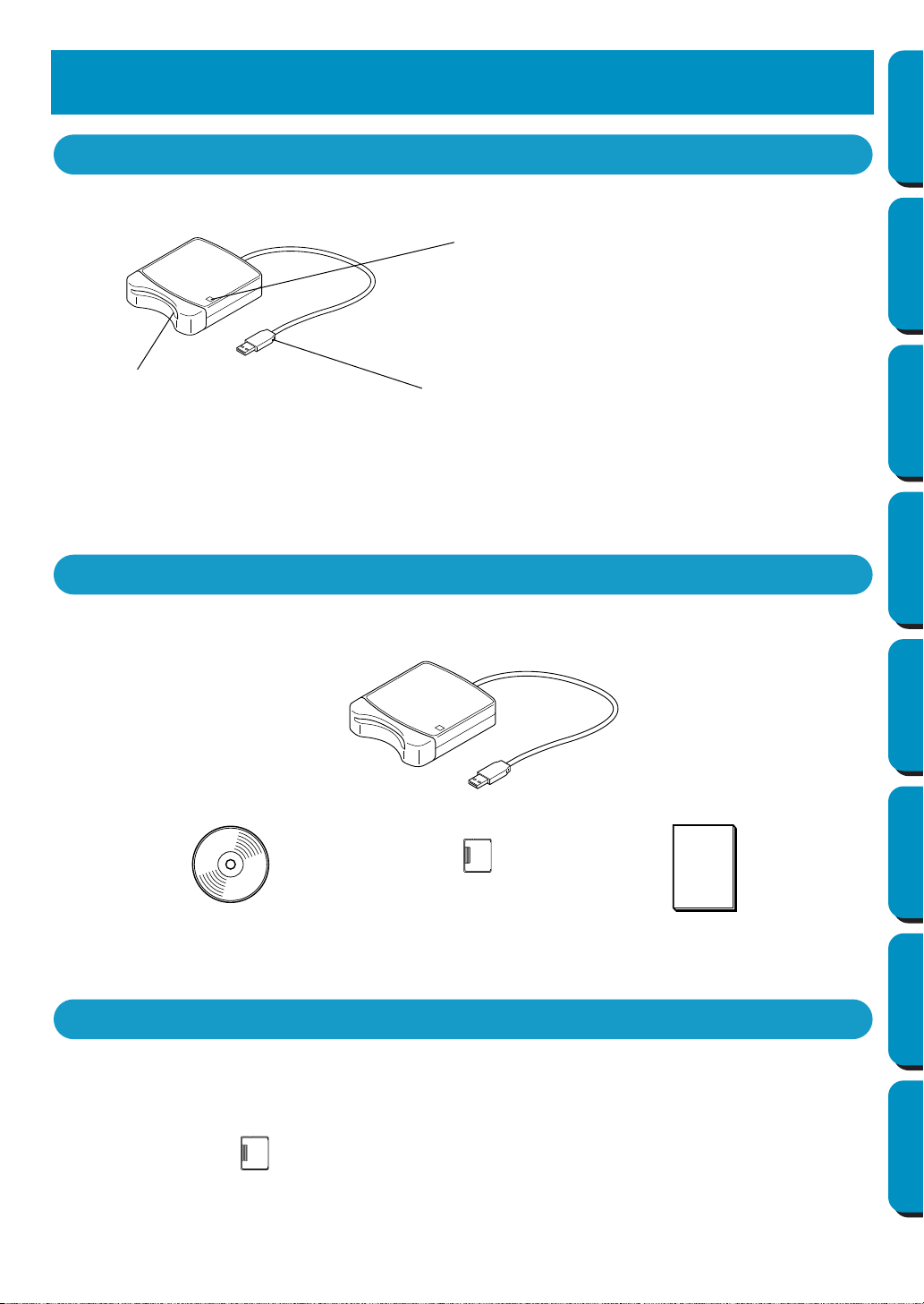
Principal Parts
USB connector
Connect to the computer.
LED indicator
This indicator lights up when the unit is turned on, and
flashes when the USB card writer module is communicat-
ing with the computer.
IMPORTANT:
Never remove an original card or unplug the
USB cable while this indicator is flashing.
Card slot
Insert an original card here.
NOTE:
Since power is supplied to the USB card writer module through the USB connection with the
computer, there is no power supply cable or power switch.
Package Contents
CD-ROM
Original card
Instruction manual
USB card writer module
Optional Supplies
Original card
IMPORTANT:
The only original cards that can be used with this
USB card writer module are those like the one
enclosed or optional original cards of the same
type.
2
Contents Before Using Getting Started Design Center Layout & Editing
Programmable
Stitch Creator
Quick Reference Alphabetic Index
System Requirements
Before installing the software on your computer, make sure that the computer meets the following
requirements.
NOTE:
• Power is supplied to this USB card writer module through the USB connection. Connect the USB card
writer module to a USB connector of the computer or to a self-powered USB hub that can supply
enough power to the card writer module. If the card writer module is not connected in this way, it may
not operate correctly.
• This product may not operate correctly with some computers and USB expansion cards.
Installation
This section describes how to install the driver and application software.
IMPORTANT:
Be sure to perform the installation according to the following instructions. If the installation is inter-
rupted or not performed according to the instructions, the software will not be installed correctly.
NOTE:
The following installation procedure includes descriptions and dialog boxes for Windows 98. The proce-
dure and dialog boxes for other operating systems may be slightly different.
1
Turn on the computer and start Windows. Quit all other applications.
2
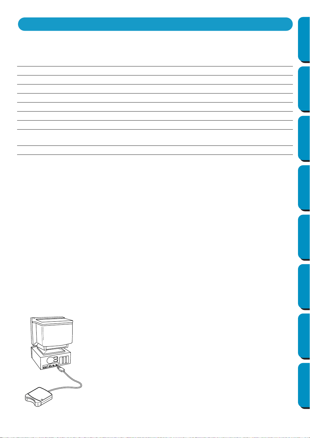
Plug the USB connector into the USB port on the computer.
Make sure that the connector is fully inserted.
Computer
IBM-PC or compatible computer originally equipped with a USB port
Operating system
Windows 98, ME, XP or 2000
Processor
Pentium 133 MHz or higher
Memory
Minimum 32 MB (64 MB or more is recommended)
Hard disk free space
Minimum 100 MB
Monitor
SVGA (800
×
600), 16-bit color or higher
Port
USB Ver. 1.1
Printer
A graphic printer that is supported by your system (if you wish to print
your images)
CD-ROM drive
Required for installation
Installing the Software
3
Contents Before Using Getting Started Design Center Layout & Editing
Programmable
Stitch Creator
Quick Reference Alphabetic Index
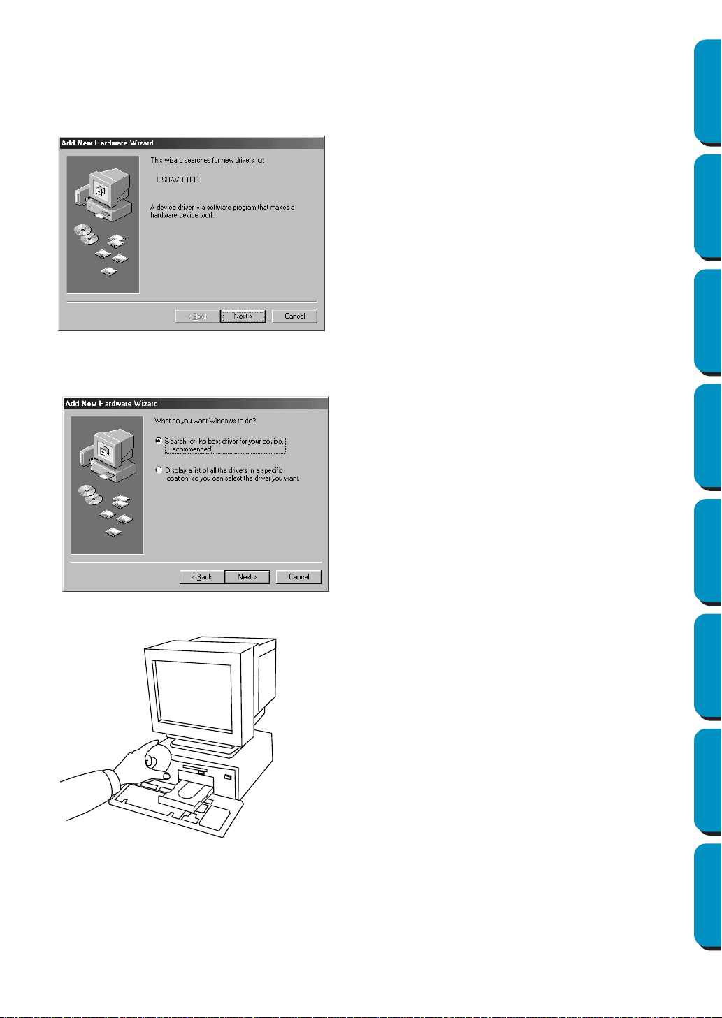
3
After a short while, the first Add New Hardware Wizard dialog box appears.
Click
Next.
IMPORTANT:
When using XP, select “Install from a list or specific location (Advanced)” on the first Wizard
screen and click Next.
4 Make sure that “Search for the best driver for your device. (Recommended)” is selected, and then
click Next.
5 Insert the enclosed CD-ROM into the computer’s CD-ROM drive.
4
Contents Before Using Getting Started Design Center Layout & Editing
Programmable
Stitch Creator
Quick Reference Alphabetic Index
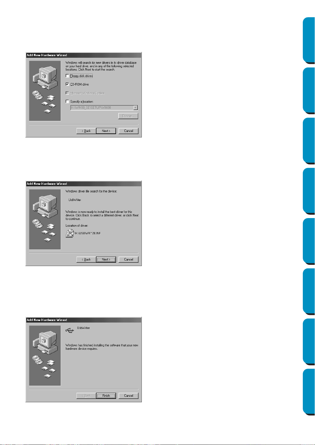
6 Select “CD-ROM drive”, and then after 5 to 10 seconds, click Next.
IMPORTANT:
Depending on the operating system, the dialog box shown in step 9 may also appear; how-
ever, the operation described in step 8 should be performed before continuing to step 9.
7 When UsbWriter appears, click Next.
IMPORTANT:
Depending on the operating system, the message “No digital signature.” may appear;
however, the installation can be continued.
8 When the dialog box shown at the right appears, click Finish.
This completes the installation of the driver software.
NOTE:
A message may appear, indicating that the computer should be restarted; however, it is not neces-
sary to restart yet, so click
Cancel.
5
Contents Before Using Getting Started Design Center Layout & Editing
Programmable
Stitch Creator
Quick Reference Alphabetic Index
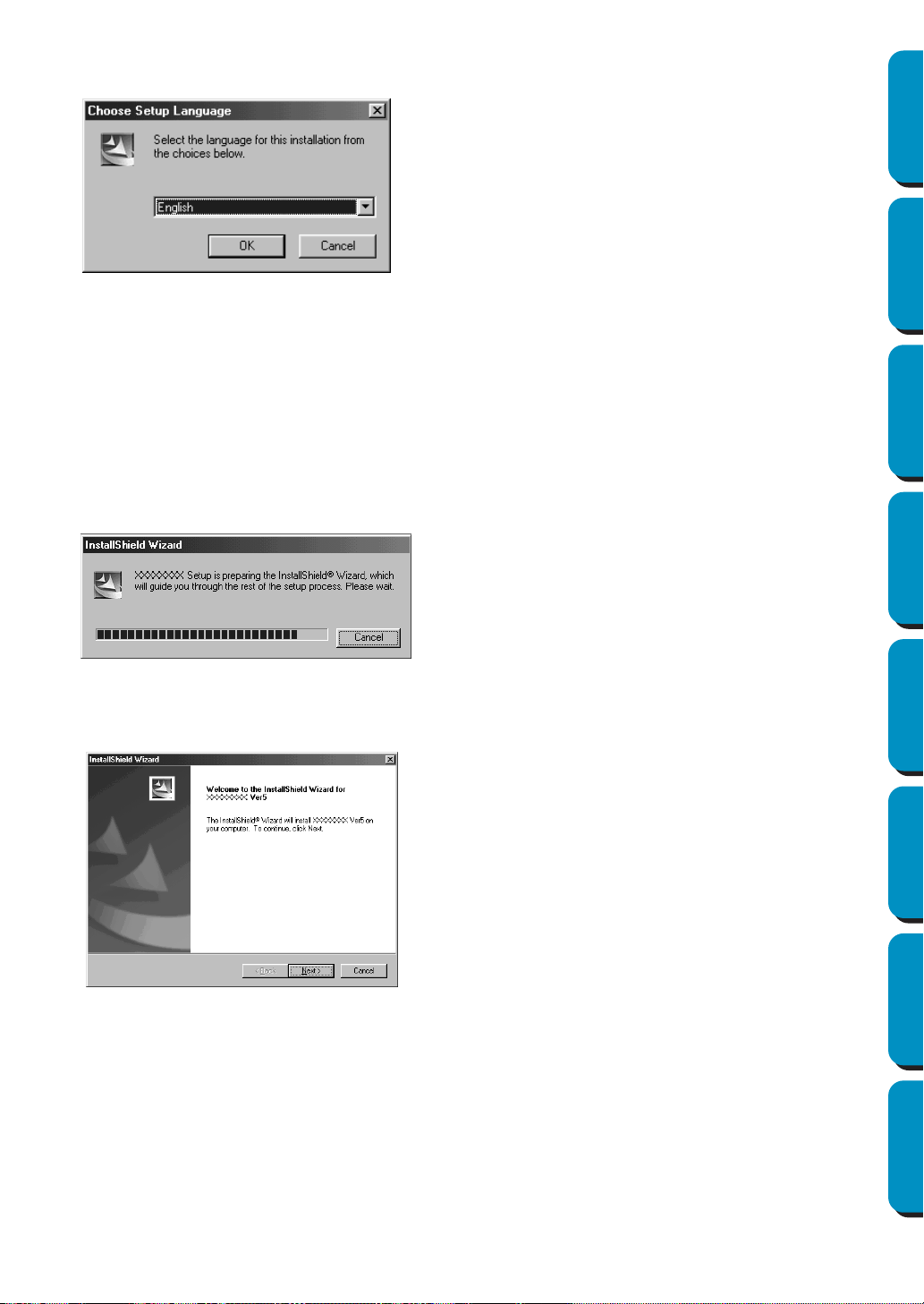
9 The Choose Setup Language dialog box appears. Select the desired language, and then click OK.
0 After a short while, the application installer automatically starts up.
If the installer does not automatically start up:
• Click the Start button.
• Click Run.
The Run dialog box appears.
• Type in the full path to the installer, and then click OK to start up the installer.
For example: D:\Setup (where “D:” is the name of the CD-ROM drive)
A When the InstallShield Wizard appears, click Next to continue with the installation.
6
Contents Before Using Getting Started Design Center Layout & Editing
Programmable
Stitch Creator
Quick Reference Alphabetic Index
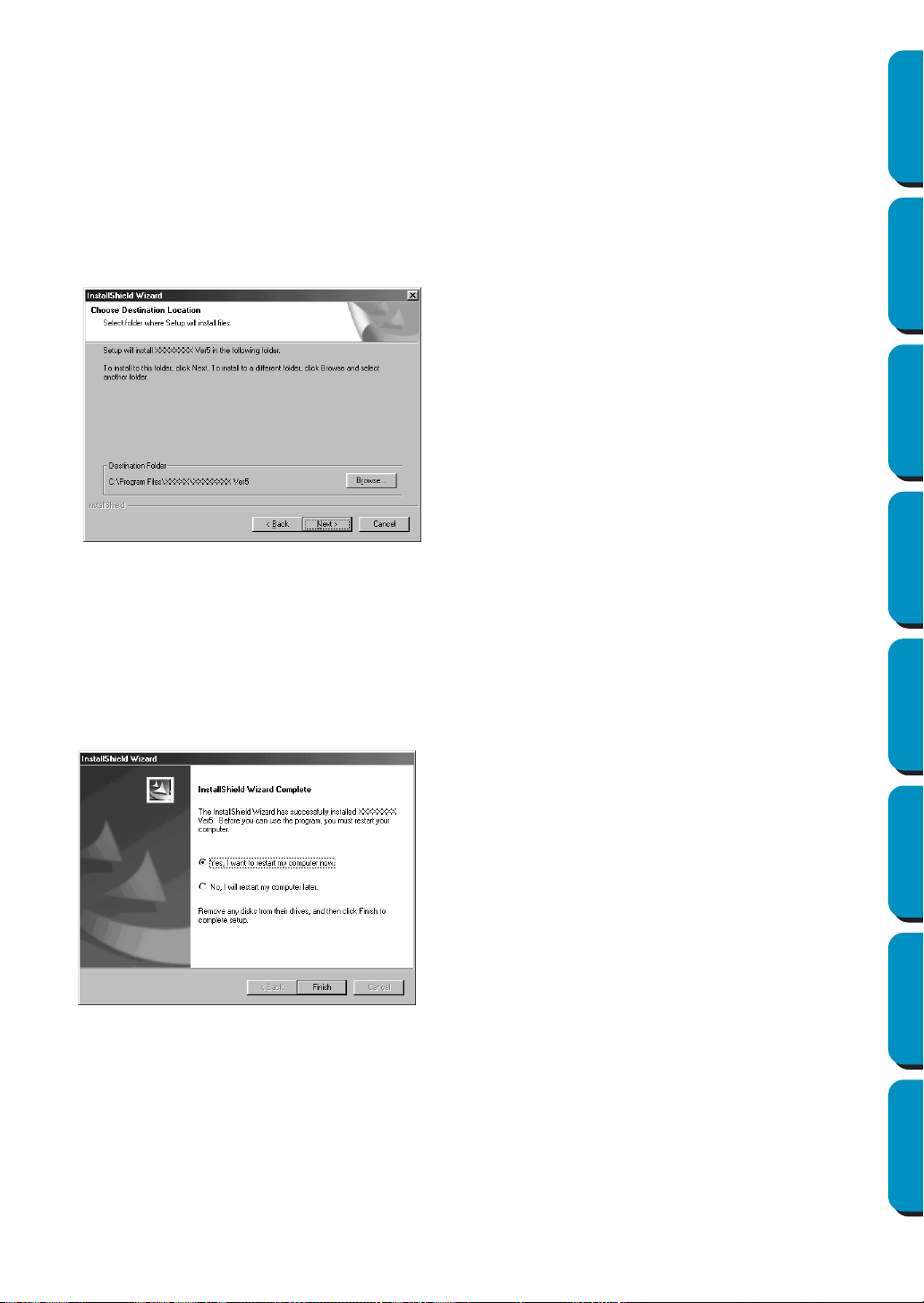
B Click Next to install the application into the default folder.
To install the application into another folder:
• Click Browse. Select the drive and folder (if necessary, type in the name of the new folder).
• When the desired folder is selected, click OK.
• The “Choose Destination Location” shows the selected folder. Click Next to install the application
into that folder.
• Click Back to return to the previous step.
• Click Cancel to exit.
C When the installation is completed, the dialog box shown at the right appears.
IMPORTANT:
With Windows 98 and ME, the computer must be restarted. Be sure to click Restart to com-
plete the setup.
NOTE:
With other operating systems, it is not necessary to restart the computer. Click Finish to complete the
setup.
This completes the entire setup operation.

7
Contents Before Using Getting Started Design Center Layout & Editing
Programmable
Stitch Creator
Quick Reference Alphabetic Index
Online Registration
If you wish to be contacted about upgrades and provided with important information such as, future prod-
uct developments and improvements, you can register your product online by following a simple registra-
tion procedure.
Click Online Registration on the Help menu to start up the installed Web browser and open the online
registration page on our Web site.
If you wish to be contacted about upgrades and provided with important information such as, future prod-
uct developments, you can register your product online by following a simple registration procedure.
IMPORTANT:
Online registration may not be available in some areas.
Uninstallation
1
Turn on the computer and start Windows.
2 Click the Start button in the task bar, select Setting, and then click Control Panel.
3 In the Control Panel window, double-click “Add/Remove Programs”.
4 In the Add/Remove Programs Properties dialog box, select program, and then click Add/Remove.
Technical Support
Please contact Technical Support if you have a problem.
Please check the company web site to find the Technical Support address for your area.
IMPORTANT:
Have the following information ready before contacting Technical Support.
• The make and model of your PC you are using as well as the Windows version. (Please check
the system requirements for this product once again. See page 2.)
• Information on any error messages that appear.
8
Contents Before Using Getting Started Design Center Layout & Editing
Programmable
Stitch Creator
Quick Reference Alphabetic Index
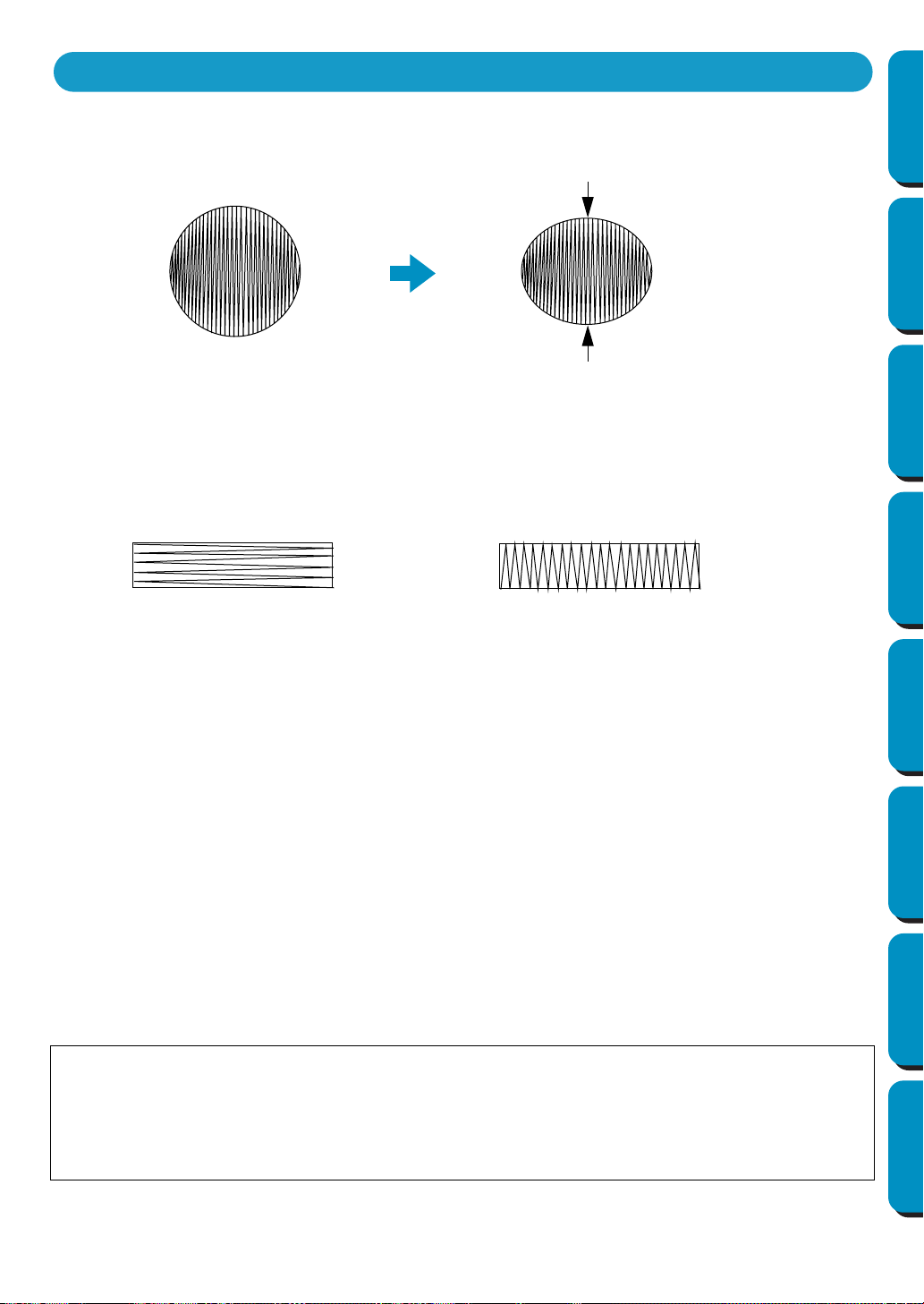
When Satin stitch is used in a wide area, the stitched area may shrink after sewing, depending on the
material and the type of thread used. When this happens, switch to this alternate method: Select Fill
stitch and use a stabilizer material on the reverse side of the fabric.
Note: When using Satin stitch in a wide area, the needle may move out of position by about 10 mm with
some machines. To avoid this, use the above mentioned alternate method.
To limit shrinking, set the stitch direction perpendicular to the larger edge of the area.
After creating an embroidery pattern made of several different parts (in Design Center or Layout & Edit-
ing), make sure that you check the sewing order and correct it if necessary.
With Design Center, the default sewing order is the order in which the sewing attributes are set.
With Layout & Editing, the default sewing order is the order in which the elements are drawn.
There are two ways of enlarging or reducing an imported embroidery pattern in Layout & Editing. You
may choose to simply scale your pattern with the selection cursor or apply the Stitch to Block function to
the pattern and then scale it.
When you scale an imported pattern, the number of stitches that will be sewn remain the same, resulting
in a change of embroidery quality if the size of the pattern is greatly changed.
Selecting the Sew – Stitch to Block command, then scaling a pattern allows you to keep the original
embroidery quality of the pattern, as the number of stitches that will be sewn automatically adapt to the
new size. Selecting the “Normal” sensitivity setting of the Stitch to Block function will allow you to main-
tain the embroidery quality in most cases. Selecting a finer density setting in the Stitch to Block Sensitiv-
ity dialog will allow you to obtain a more complex embroidery; selecting a coarser density will create a
simpler embroidery.
When a pattern is scaled only moderately, it may not be necessary to apply the Stitch to Block function.
This system allows you to create a wide variety of embroidery patterns and supports wider ranges for
the setting of the sewing attributes (thread density, sewing pitch, etc.). However, the final result also
depends on your particular sewing machine model. We recommend that you make a trial sewing sam-
ple with your sewing data before sewing on the final material. Remember to sew your trial sample on
the same fabric, using the same needle and the same machine embroidery thread as your final mate-
rial.
Tips and Techniques for Creating Embroidery Patterns
Data
After sewing
Shrinking more likely to occur
Shrinking less likely to occur
9
Contents Before Using Getting Started Design Center Layout & Editing
Programmable
Stitch Creator
Quick Reference Alphabetic Index
Introduction
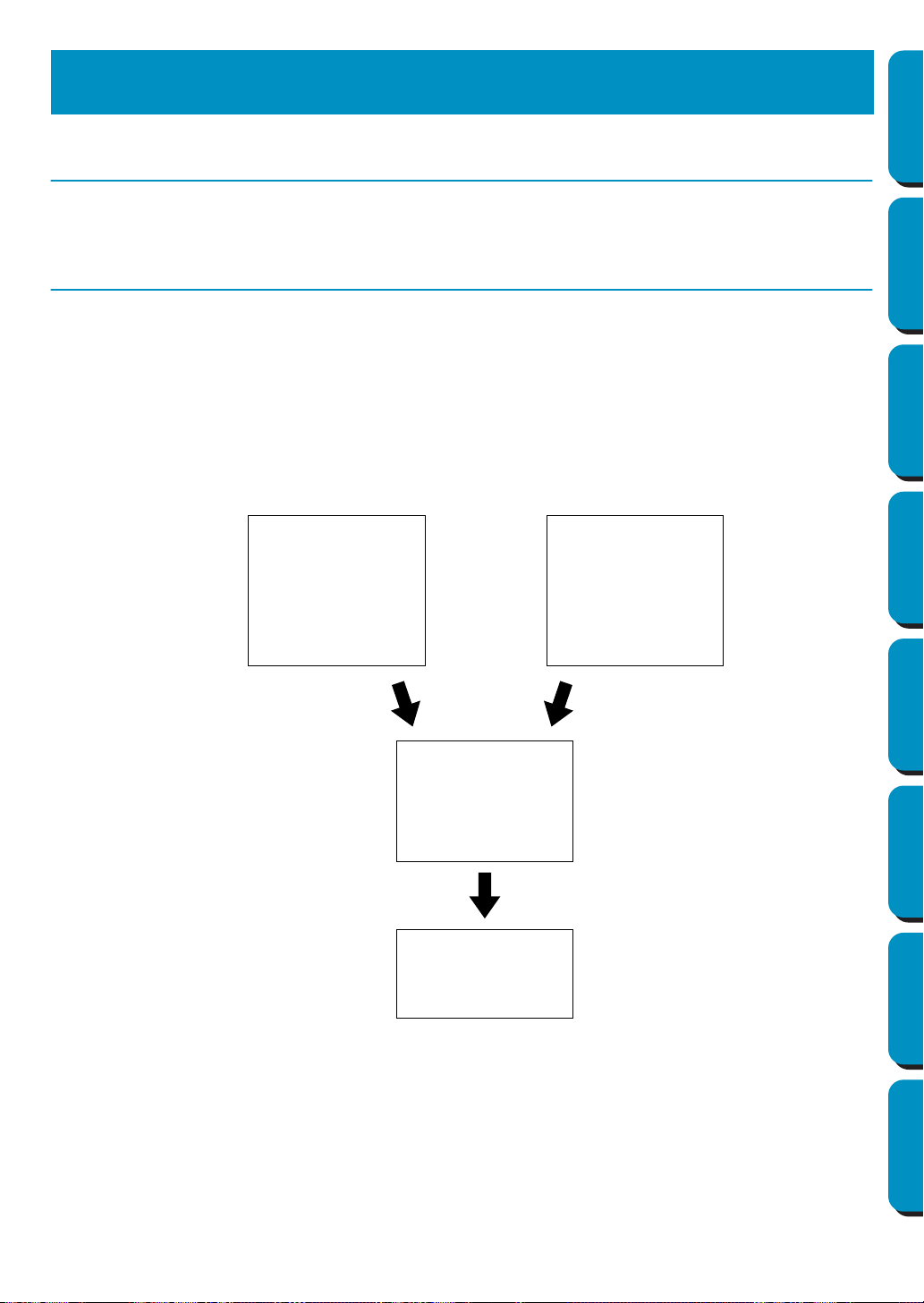
This package contains three applications.
About this Chapter
The next three sections of this chapter are organized as a tutorial to provide you with a hands-on intro-
duction to the different features of the applications.
First, using the Auto Punch function in Layout & Editing, you will create an embroidery pattern automati-
cally from an image. The embroidery pattern can also be created in Design Center using the 4-stage pro-
cedure described later.
Next, the pattern will be imported into Layout & Editing. You will learn how to add a few components to
the embroidery image and to organize the layout.
In the third section, you will then learn how to use Programmable Stitch Creator to edit a programmable
stitch in order to create your own.
■ Layout & Editing
Layout & Editing is used to automatically create embroidery patterns from images, combine images and
text, and create embroidery data that can be written to an Original card. The images may come from
scanning a printed image or can be created with an application like Paint
. The extension of the image
files must be bmp, tif, jpg, j2k, pcx, wmf, png, eps, pcd, or fpx. In addition, the following type of embroidery
data can be incorporated into the embroidery pattern.
Getting Started
1.
The Auto Punch
function of Layout &
Editing can be used to
create an embroidery
pattern automatically.
2.
Layout & Editing
will be used to combine
images and text and
organize the layout.
3.
Programmable Stitch
Creator will be used.
1.
Design Center can be
used create an
embroidery pattern.
or
→ page 11
→ page 16
→ page 29
→ page 50

10
Contents Before Using Getting Started Design Center Layout & Editing
Programmable
Stitch Creator
Quick Reference Alphabetic Index
◆ Embroidery patterns created with Design Center
◆ Embroidery patterns on Embroidery cards purchased from your dealer (Note that some patterns can-
not be read.)
◆ Embroidery patterns in the Tajima, Melco, Pfaff and Husqvarna formats
◆ Patterns created within Layout & Editing itself (These patterns include text, circles and related
shapes, rounded boxes, polygonal lines, curves and manual punching patterns.)
After gathering the different components of your embroidery picture, you can use the layout functions to
modify their relative position, orientation and scale.
When an embroidery image is complete, you can save it (the file name extension will be pes) and write it
to an Original card. The Original card can then be inserted into your sewing machine and the embroidery
process continued.
■ Design Center
Design Center is used to manually create embroidery patterns from images. The images may come from
scanning a printed image or can be created with an application like Paint
. The extension of the image
files must be bmp, tif, jpg, j2k, pcx, wmf, png, eps, pcd, or fpx. Design Center automatically detects out-
lines in the image and replaces them with broken lines that can be edited and assigned sewing
attributes.
The procedure is divided in four stages:
◆ Stage 1 – Original Image: You open the image file and select one or more colors that the application
will use to retrace the outlines.
◆ Stage 2 – Line Image: The original color image is replaced with a black and white image (the colors
selected in Stage 1 become black, and all the other colors become white). You can edit this image
using pens and erasers of different thicknesses. (You can also start at this step and draw a complete
black and white image by hand.)
When the image is ready, you set and start the automatic retracing process.
◆ Stage 3 – Figure Handle: The black and white image is replaced with a set of outlines made of edit-
able broken lines. You can edit the broken lines by moving, inserting or deleting points.
◆ Stage 4 – Sew Setting: In this final step, you apply sewing attributes (thread color and stitch type) to
the outlines and regions inside.
At any stage, you can save your work to retrieve it later. Up to stage 2, the file will be saved with the
extension pel. In stages 3 and 4, the file will be saved with the extension pem.
Saving your work as you move through the stages will be helpful if you make changes, then later decide
to use the original pattern.
When your image has reached stage 4, you can import it in Layout & Editing. The image will be consid-
ered a single object by Layout & Editing, which means that you will be able to move and scale it, but you
will not be able to edit the outline. You can however change the pattern and some of the sewing attributes
after applying the Stitch to Block function.
■ Programmable Stitch Creator
Programmable Stitch Creator allows you to create, edit and save fill stitch patterns, which you can apply
to the enclosed regions of patterns, both in Design Center and Layout & Editing. The fill stitch pattern
files are saved as pas files. The application comes with a number of pas files, which you can use as such
or edit to enhance your embroidery patterns.
11
Contents Before Using Getting Started Design Center Layout & Editing
Programmable
Stitch Creator
Quick Reference Alphabetic Index
In this section, we are going to create an embroidery pattern automatically. That pattern will be created
by automatic retracing of an image. This pattern will be used later as the stepping stone to creating a
more complex embroidery picture.
Please follow these instructions step by step, in the sequence given. If you have to interrupt your training
for any reason, it is recommended to save the file. You will be able to retrieve it later and resume your
work.
The complete procedure will take us through the different steps of a normal working session with Design
Center and will introduce you to its most important features.
Step 1 Starting Layout & Editing
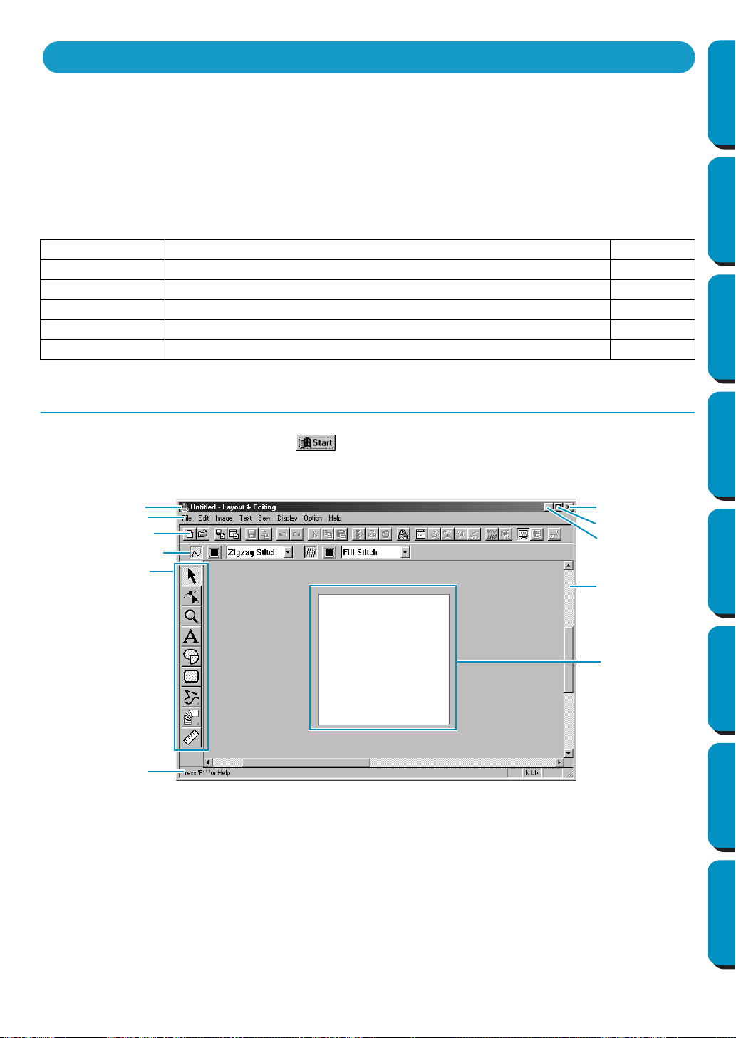
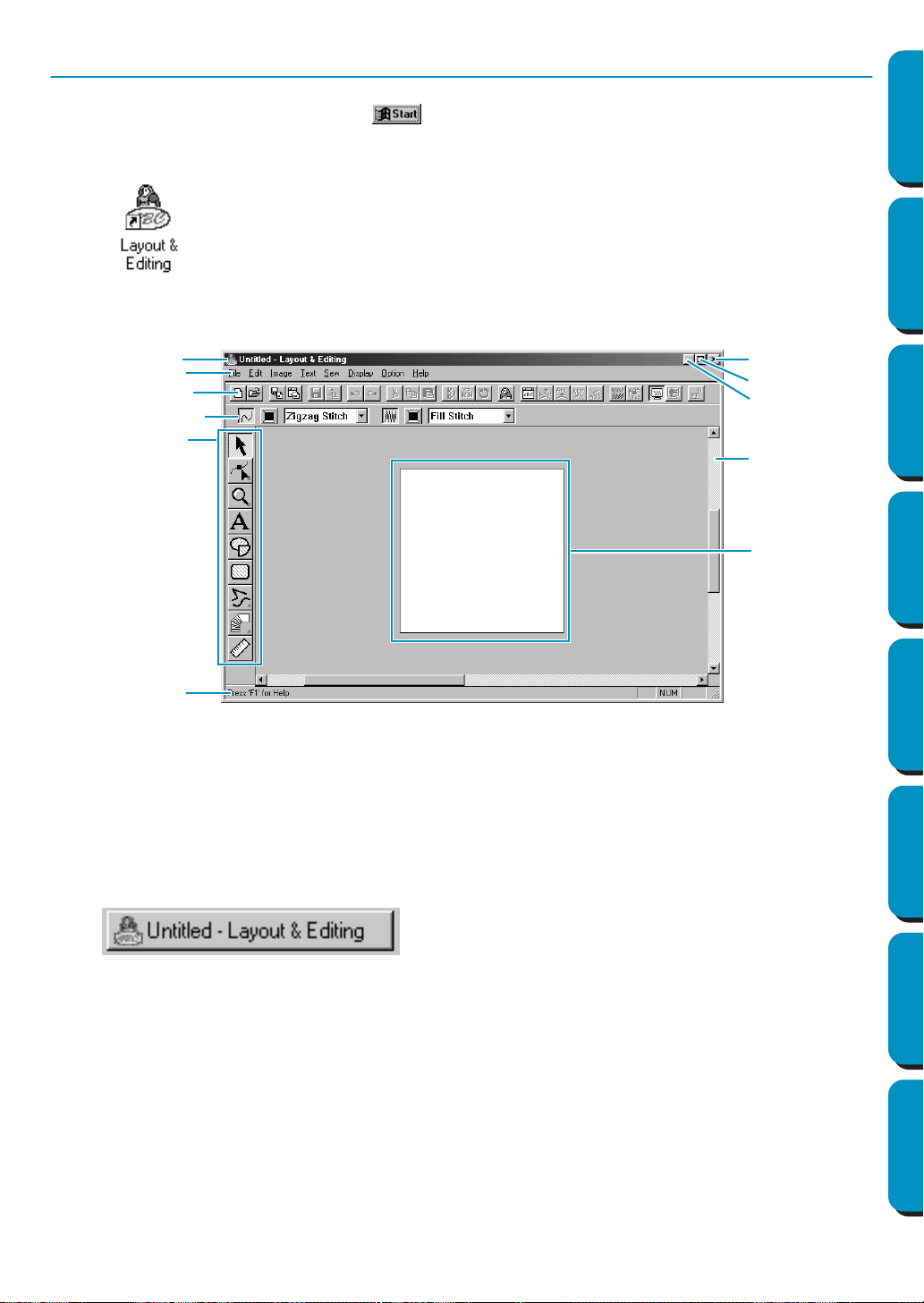
1 To start Layout & Editing, click the button, select Programs, then Version 5.0, and then click
Layout & Editing to open the Layout & Editing window.
Step 1 Starting Layout & Editing page 11
Step 2 Opening an Image page 12
Step 3 Editing the Image page 13
Step 4 Using the Wizard and Selecting the Auto Punch Function page 14
Step 5 Automatically Extracting Pattern Outlines page 14
Step 6 Automatically Creating an Embroidery Pattern page 15
Using the Auto Punch Function
Menu bar
Toolbar
Sewing attributes bar
Tool box
Work area
Design Page
Status bar
Maximize button
Close button
Title bar
Minimize button
12
Contents Before Using Getting Started Design Center Layout & Editing
Programmable
Stitch Creator
Quick Reference Alphabetic Index
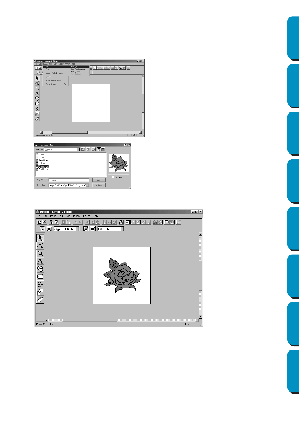
Step 2 Opening an Image
We are now going to open an image and convert it into an embroidery image.
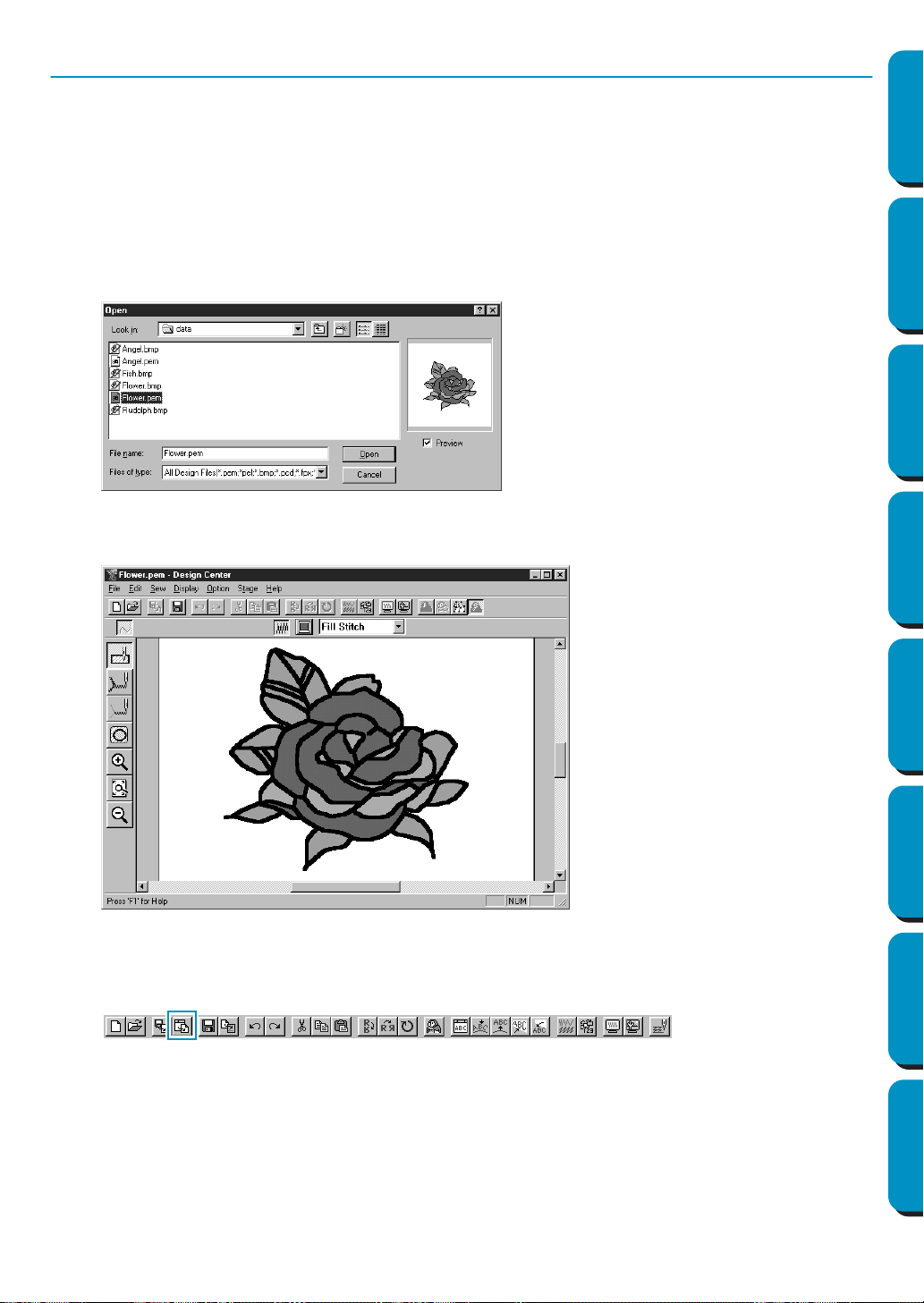
1 Click Image on the menu bar, select Input on the submenu, then click from File.
The Open dialog appears.
The image displays and is maximized to fit the work area.
◆ Select the sample file Flower.bmp in the
Data folder.
• If the Preview check box is checked, the
contents of the selected file displays in
the Preview window.
◆ Click Open to open the file and close
the dialog.
13
Contents Before Using Getting Started Design Center Layout & Editing
Programmable
Stitch Creator
Quick Reference Alphabetic Index
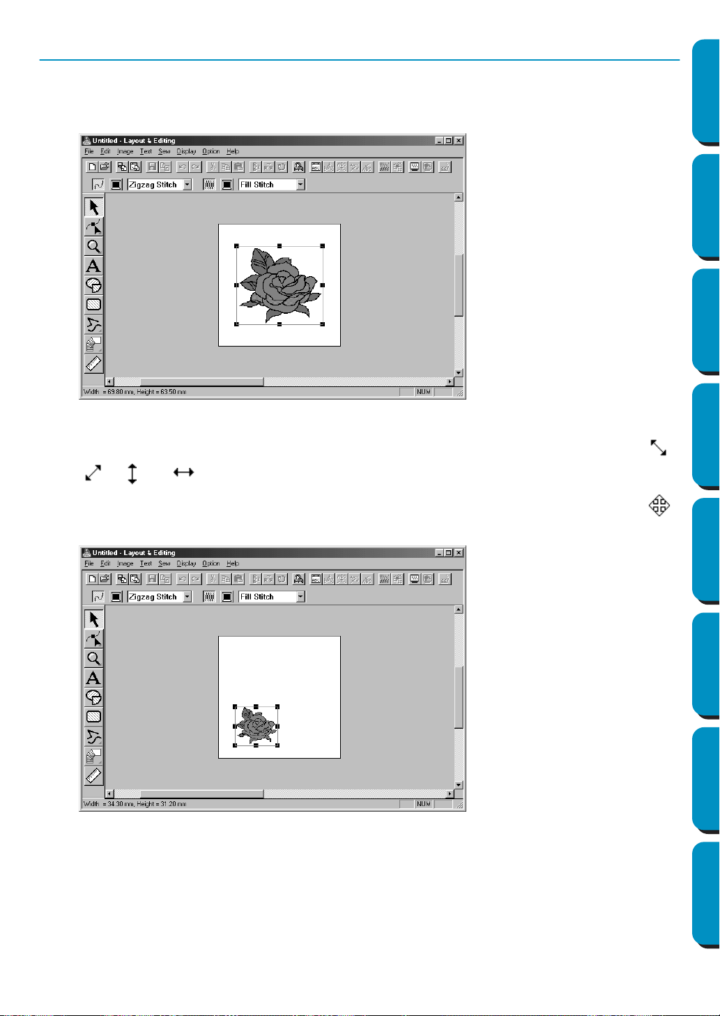
Step 3 Editing the Image
1 Click Image on the menu bar, then click Modify.
2 Handles appear around the selected image.
The Status bar shows the dimensions (width and height) of the selected pattern.
3 Move the cursor over a handle of the selected pattern, and then after the cursor changes to ,
, , or , adjust the size of the pattern.
4 Move the cursor over the selected pattern, and then after the shape of the cursor changes to ,
drag the pattern to the desired location.
14
Contents Before Using Getting Started Design Center Layout & Editing
Programmable
Stitch Creator
Quick Reference Alphabetic Index
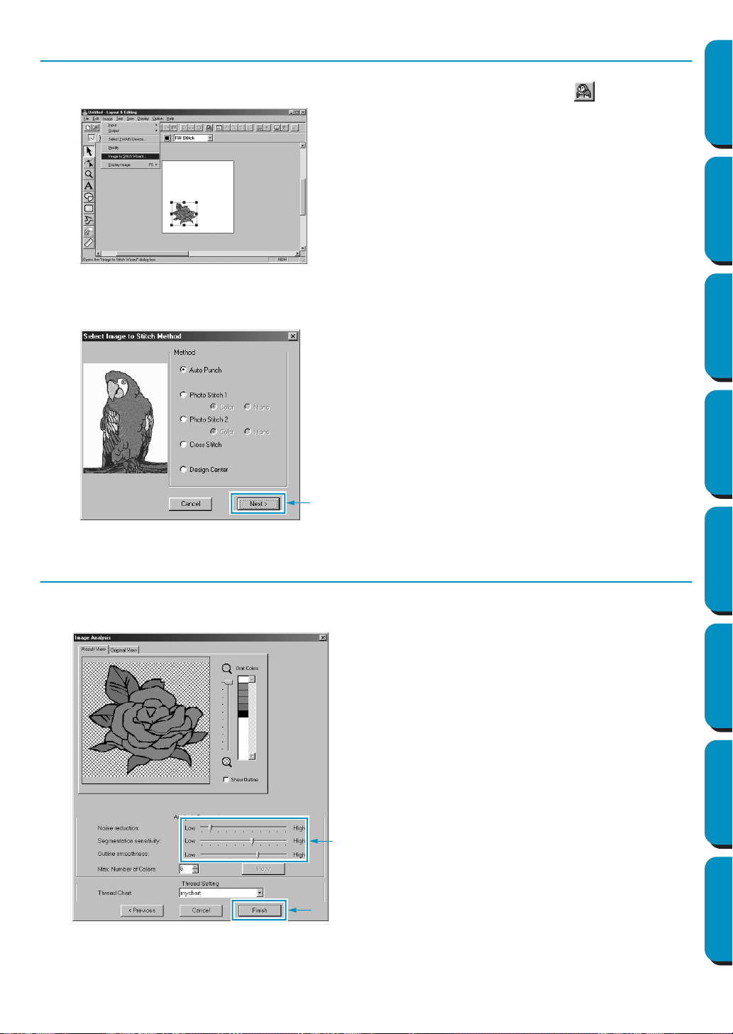
Step 4 Using the Wizard and Selecting the Auto Punch Function
1 Click Image on the menu bar, then click Image to Stitch Wizard. Otherwise, click on the Toolbar.
2 On the Select Image to Stitch Method dialog that appears, click the Auto Punch check box to select
it, and then click
Next.
Step 5 Automatically Extracting Pattern Outlines
1 Outlines are automatically extracted from the image and the Image Analysis dialog appears.
2 After the necessary settings are selected, click Finish.
• The following stitch methods are also avail-
able.
- Photo Stitch 1 (Color and Mono)
See the function details on page 183.
- Photo Stitch 2 (Color and Mono)
See the function details on page 190.
- Cross Stitch
See the function details on page 195.
- Design Center, Starting Design Center
See “Using Design Center” on page 16 or the
function details on page 61.
◆ Detailed settings for the imported image can
be adjusted and, if Retry is clicked, the new
settings can be applied.
◆ Areas that are not to be sewn appear with a
crosshatch pattern. Click each area to set
whether it should be sewn or not.
15
Contents Before Using Getting Started Design Center Layout & Editing
Programmable
Stitch Creator
Quick Reference Alphabetic Index
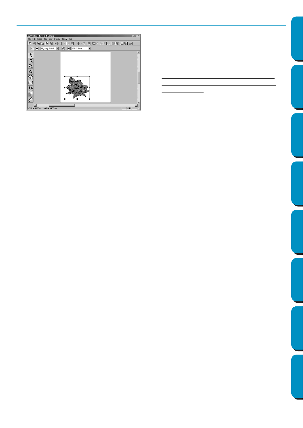
Step 6 Automatically Creating an Embroidery Pattern
◆ The embroidery pattern appears.
◆ The stitching and thread colors of the finished
embroidery pattern can be changed as you
wish.
◆ To continue editing the embroidery pattern,
continue with step 5 of “Using Layout & Edit-
ing” on page 36.
16
Contents Before Using Getting Started Design Center Layout & Editing
Programmable
Stitch Creator
Quick Reference Alphabetic Index
In this section, we are going to create an embroidery pattern. That pattern will be created by automatic
retracing of an image. This pattern will be used later as the stepping stone to creating a more complex
embroidery picture.
The complete procedure will take us through the different steps of a normal working session with Design
Center and will introduce you to its most important features.
Please follow these instructions step by step, in the sequence given. If you have to interrupt your training
for any reason, it is recommended to save the file (see Step 9). You will be able to retrieve it later and
resume your work.
Step 1 Starting Design Center page 17
Step 2 Opening an Image page 18
Step 3 Converting to Line Image page 19
Step 4 Editing Lines page 20
Step 5 Converting to Figure Handle Image page 22
Step 6 Moving to Sew Setting page 23
Step 7 Setting Sewing Attributes page 23
Step 8 Previewing the Image page 28
Step 9 Saving the File page 28
Using Design Center
17
Contents Before Using Getting Started Design Center Layout & Editing
Programmable
Stitch Creator
Quick Reference Alphabetic Index
Step 1 Starting Design Center
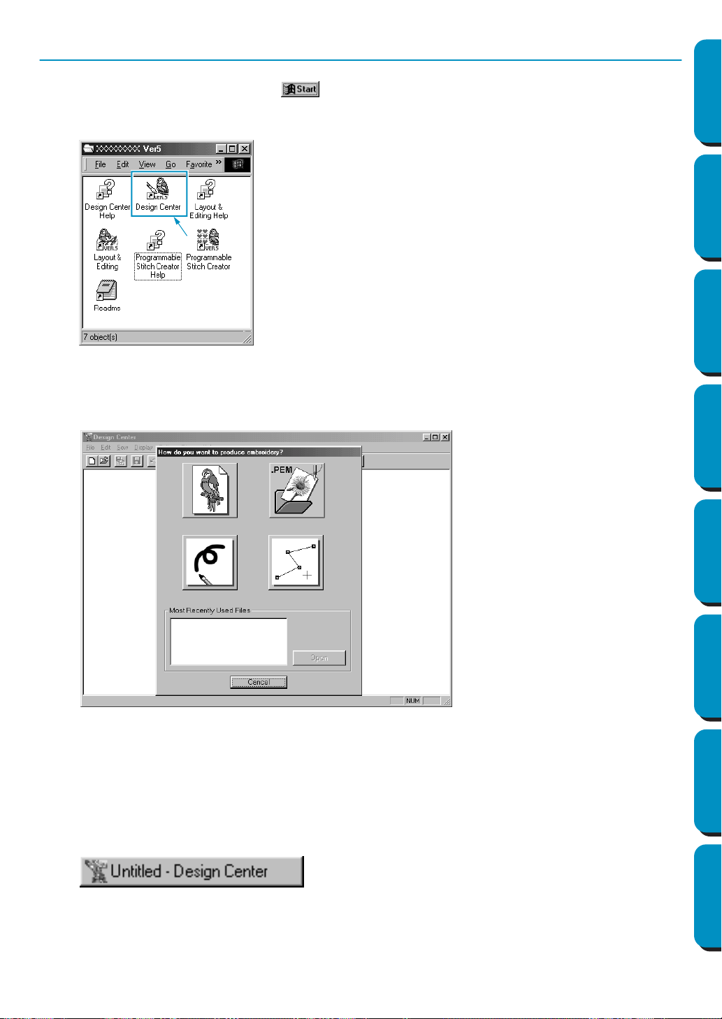
1 To start Design Center, click the button, select Programs, then Version 5.0, and then click
Design Center to open the Design Center window.
You may also double-click the Design Center icon in the program group.
You can also click Option on the menu bar of Layout & Editing, then click Design Center on the sub-
menu.
The Design Center window appears.
The window size will be smaller than the display area on the screen of your personal computer.
2 To make the Design Center window fill up the available space on your screen, click the maximize
button on the right side of title bar.
If you are working with other programs, you can reduce the Design Center window temporarily to
an icon (see icon below) by clicking the minimize button on the right side of the title bar. You can
then access the other windows and icons on the display screen by using the mouse.
To return to the Design Center window, click the icon, bearing the name of the opened document,
at the bottom of your screen.
If the shortcut icon for Design Center is
created, for example, on computer desk-
top, double-click it to start program.
18
Contents Before Using Getting Started Design Center Layout & Editing
Programmable
Stitch Creator
Quick Reference Alphabetic Index
Step 2 Opening an Image
We are now going to open an image and convert it into an embroidery image. If the Wizard dialog
appears, click Cancel to close it.
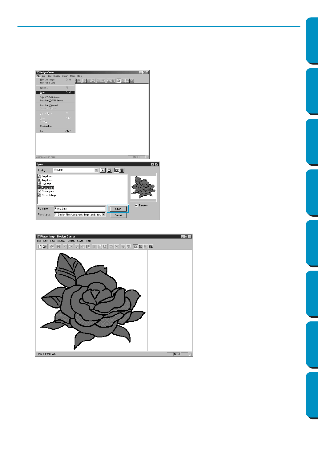
1 Click File on the menu bar, then click Open on the submenu.
The Open dialog appears.
The image displays and is maximized to fit the work area.
◆ Select the file Flower.bmp in the Data
folder.
• If the Preview check box is checked, the
contents of the selected file displays in
the Preview window.
◆ Click Open to open the file.
• Double-clicking the file name will also
open the file and close the dialog.
19
Contents Before Using Getting Started Design Center Layout & Editing
Programmable
Stitch Creator
Quick Reference Alphabetic Index
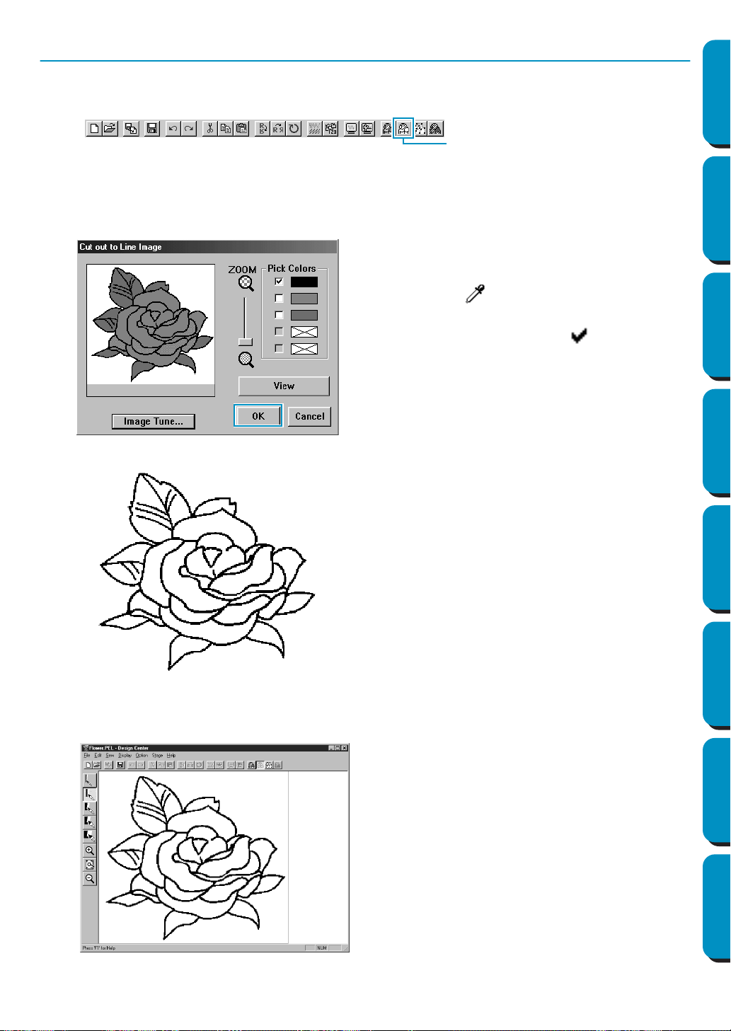
Step 3 Converting to Line Image
1 Move to line image: Click Stage on the menu bar, then click To Line Image on the submenu. You can
also click the button of the Toolbar shown below:
NOTE: Many menu functions can be activated by clicking a button on the Toolbar.
The
Cut out to Line Image dialog will display. In this dialog, you will select the color(s) that will be
used to make the outline of the image.
2 When you click OK, the line image displays.
◆ If necessary, scroll and zoom the image.
◆ Move the cursor over the image. Its shape
changes to . Click on any point of the out-
line. The selected color displays in the upper
box under
Pick Colors and a appears in the
check box to show that the color is selected.
• When the outline of the image uses more than one
color, you can repeat to select a total of five colors.
If you try to select more, colors are scrolled down,
and the color that was at the bottom is deselected.
• If you selected a color by mistake, simply click
its check box to deselect it.
◆ Click View to see the effect of your selection.
• If you wanted to select another choice of color,
click
Cancel. The image displays again and you
can repeat this step with another color.
◆ If your preview image looks like the one shown
here, click OK to confirm the outline of your pattern.
◆ Click Cancel to exit and go back to the image.
◆ If necessary, click
Image Tune to reduce the col-
ors or the noise. (page 109)
• At this stage, the data can be saved as a *.pel
file.
To Line Ima
g
e
20
Contents Before Using Getting Started Design Center Layout & Editing
Programmable
Stitch Creator
Quick Reference Alphabetic Index
Step 4 Editing Lines
At this step, you might normally need to correct a few lines. You should especially make sure that the lines
around regions are completely closed or intersect to form a region. You may also wish to edit a line image and
either add or remove some details or your image. You can do this at this stage using the pens and erasers of
the Tool Box.
In this example, you are going practice how to use an eraser to remove some of the outline.
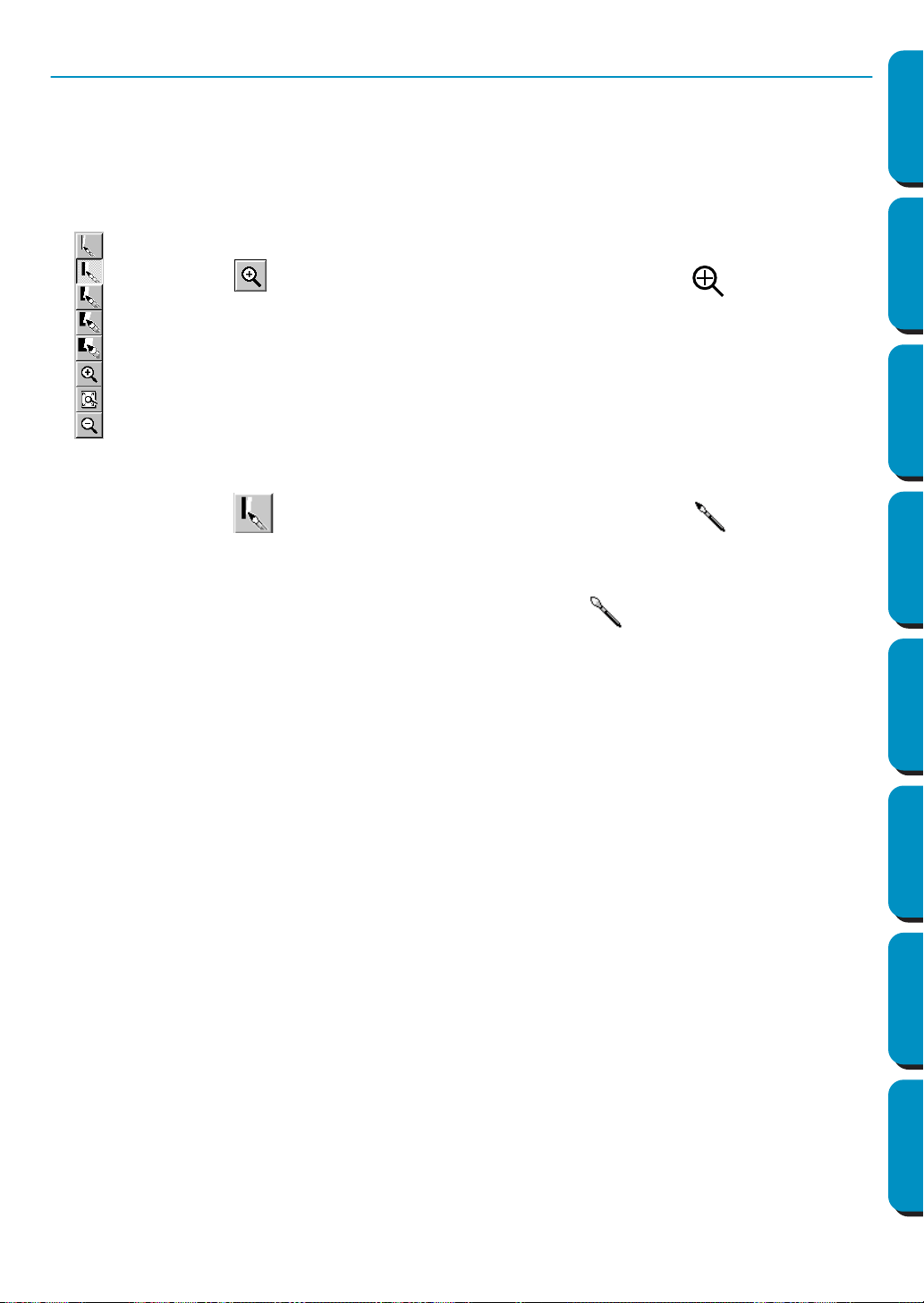
1 To make your editing job easier, enlarge the image using the zoom function.
Click on the Tool Box. The shape of the cursor changes to when you move
it over the work area.
2 Drag the cursor over the pattern and click. The area is enlarged as soon as you
release the mouse. You can repeat this step several times. To zoom in on a specific
area, position the cursor to a point just next to the area, then click the left mouse but-
ton and hold it down as you move the cursor diagonally. A dotted box appears as you
drag and the selected area will be magnified when you let go of the mouse button.
For a more complete description of the zoom features, see “Zoom-in Mode”, “Zoom-
out Mode” and “Fit Design Page to Window” on page 64.
3 Click on the Tool Box. The shape of the cursor changes to when you move
it over the work area.
4 Position the cursor over the first line you want to erase. Click and hold the right button
of the mouse. The shape of the cursor changes to .
5 Carefully erase the line, then move the cursor to the next line to erase and scroll the
image as needed. Repeat this procedure to delete a few petals and leaves.
NOTE:
If you deleted parts of the outline by mistake, you may need to redraw some of lines.
To do this, simply hold down the left mouse button and start drawing the line.
If you are not satisfied with your editions, you can go back to Stage 1, convert your
pattern and start editing again.
21
Contents Before Using Getting Started Design Center Layout & Editing
Programmable
Stitch Creator
Quick Reference Alphabetic Index
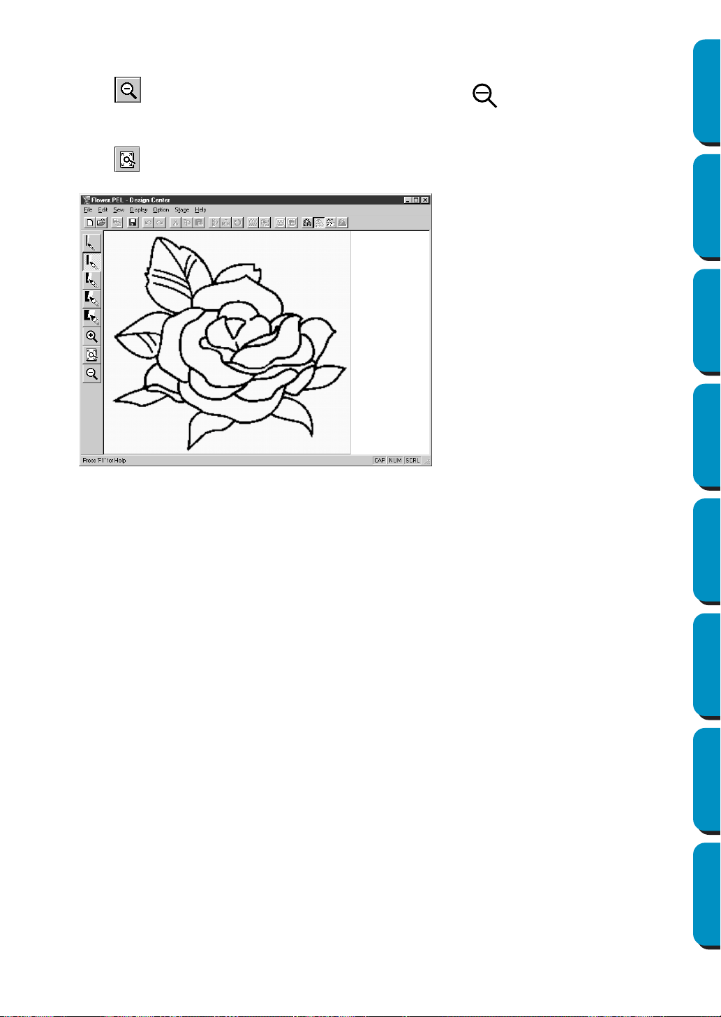
6 After editing your image, you will want to zoom out again to view the whole picture.
There are two ways of proceeding.
Click on the Tool Box. The shape of the cursor changes to when you move it over the
work area. Click a point of the Design Page and the image shrinks toward that point. Repeat this
step several times.
Click on the Tool Box. The Design Page fits the Design Center window automatically.
Your window may now look like the following:
22
Contents Before Using Getting Started Design Center Layout & Editing
Programmable
Stitch Creator
Quick Reference Alphabetic Index
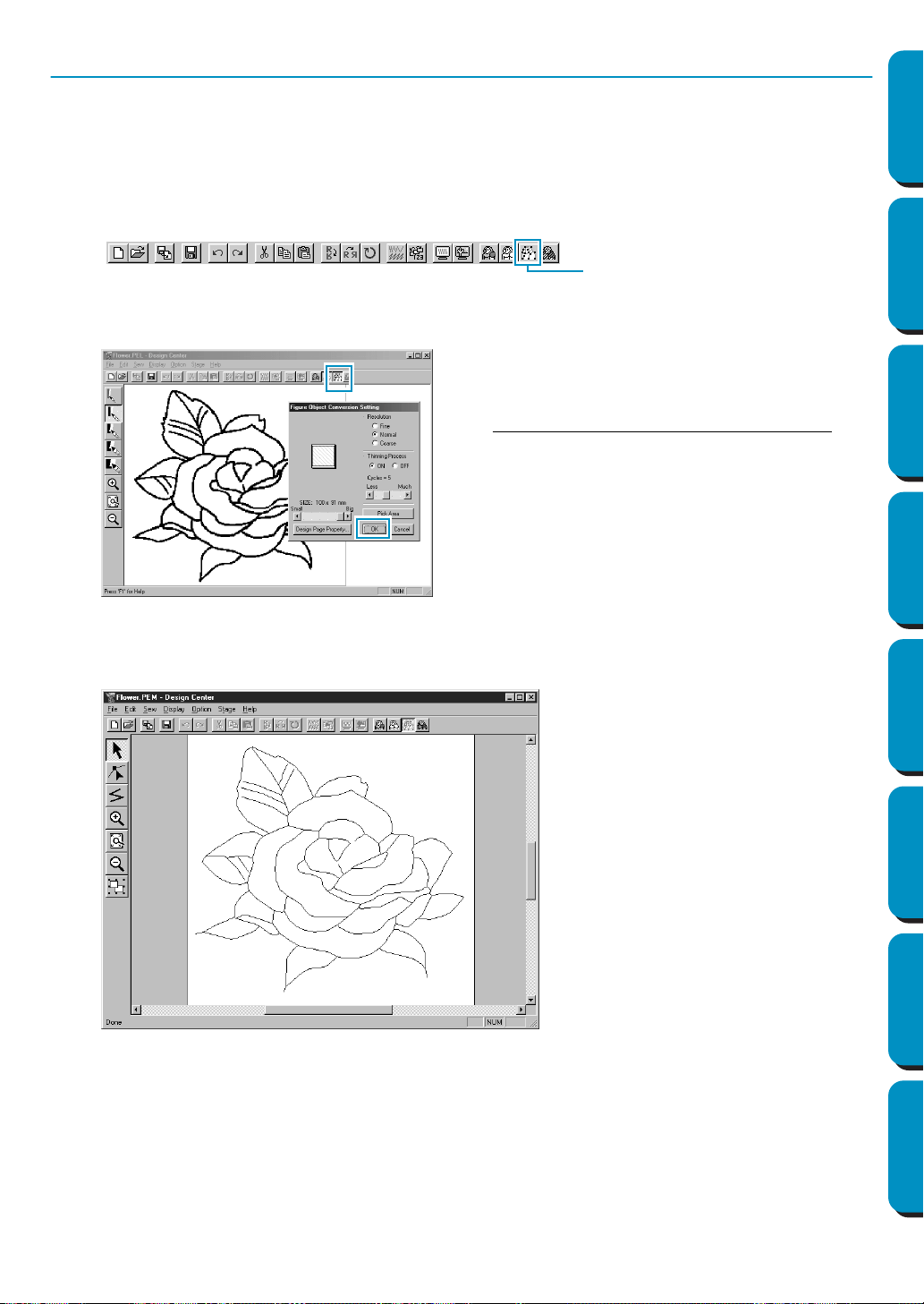
Step 5 Converting to Figure Handle Image
In Stage 2, the image is just a collection of dots or pixels. Editing in Stage 2 means adding or removing
black dots. When you move to Stage 3 (figure handle image) the application automatically follows adja-
cent black dots to detect paths and replaces them with broken lines. Those broken lines can then be
edited.
1 Click Stage on the menu bar, then click To Figure Handle on the submenu.
You can also click the button of the Toolbar shown below:
The following dialog will display.
2 When you click OK, the conversion process starts. After a while, the figure handle image appears.
The Tool Box provides editing tools to draw lines, move, delete points or insert new points, as well as
zooming tools. In this example, we will however leave the image as is. For details on how to edit the
figure handle image, see “Using the Stage 3 Tool Box” page 65.
NOTE:
You may also change the Design Page properties at this stage using the menu command Option -
Design Page Property
, which will open the Design Page Property dialog.
This dialog allows you to preview how the image
will fit in the selected Design Page. The Design
Page size is the actual size of the area to be
sewn.
◆ Lea
ve all settings unchanged and click OK.
• For more details about the settings, see
“Design Page Property” on page 106 and “To
Figure Handle” on page 110.
To Figure Handle
23
Contents Before Using Getting Started Design Center Layout & Editing
Programmable
Stitch Creator
Quick Reference Alphabetic Index
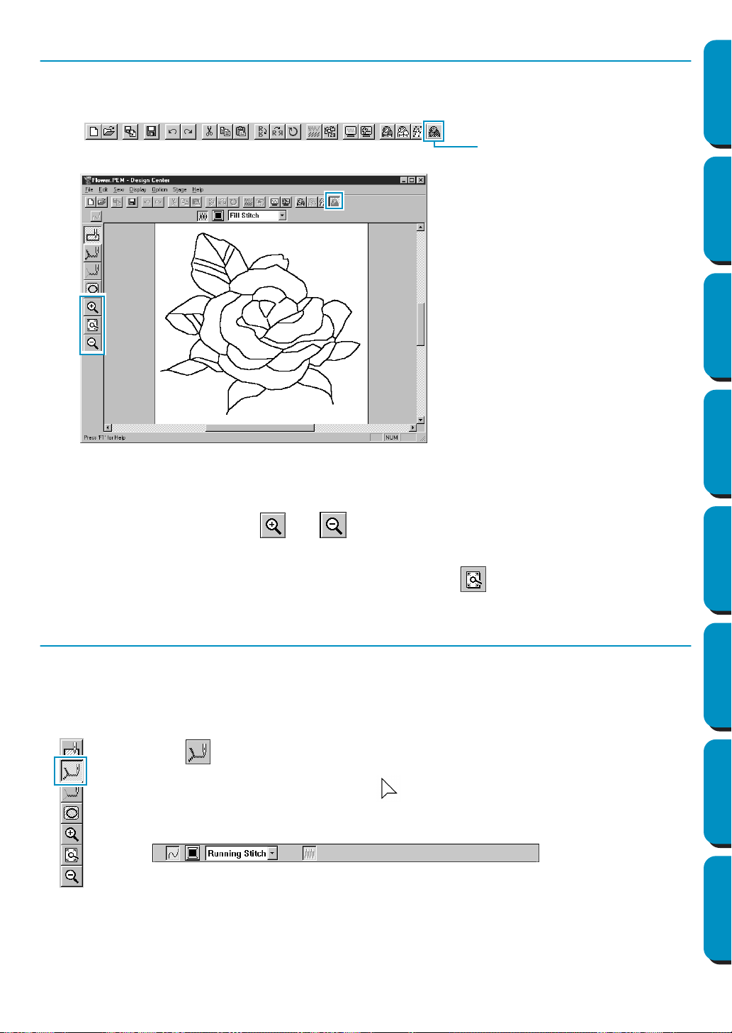
Step 6 Moving to Sew Setting
1 Click Stage on the menu bar, then click To Sew Setting on the submenu.
You can also click the button of the Toolbar shown below:
The Sew Setting window appears.
In this stage, you can set and check the sewing attributes of each part of the pattern. You can also
set a pair of patterns for hole sewing in order to avoid sewing twice at the same place.
The other tools available are for zooming.
2 To zoom in and out, use the and buttons on the Tool Box in the same way as you did at
the Figure Handle stage.
3 To maximize the Design Page so that it fits the window, click on the Tool Box.
Step 7 Setting Sewing Attributes
We are now going to apply sewing attributes to the different parts on the picture.
■ Setting the outlines
1
Click on the Tool Box.
The shape of the cursor changes to and is displayed together with a small figure
of the Tool Box button.
The Sewing Attributes bar now looks like this:
To Sew Settin
g
24
Contents Before Using Getting Started Design Center Layout & Editing
Programmable
Stitch Creator
Quick Reference Alphabetic Index
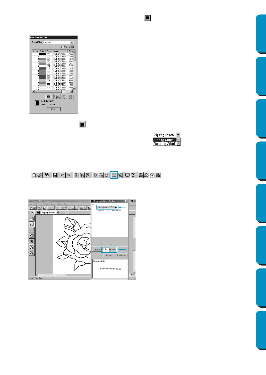
2 To set the outline color: Click the Line color button on the Sewing Attributes bar to display the
Line Thread Color dialog.
The Line color button shows the selected color.
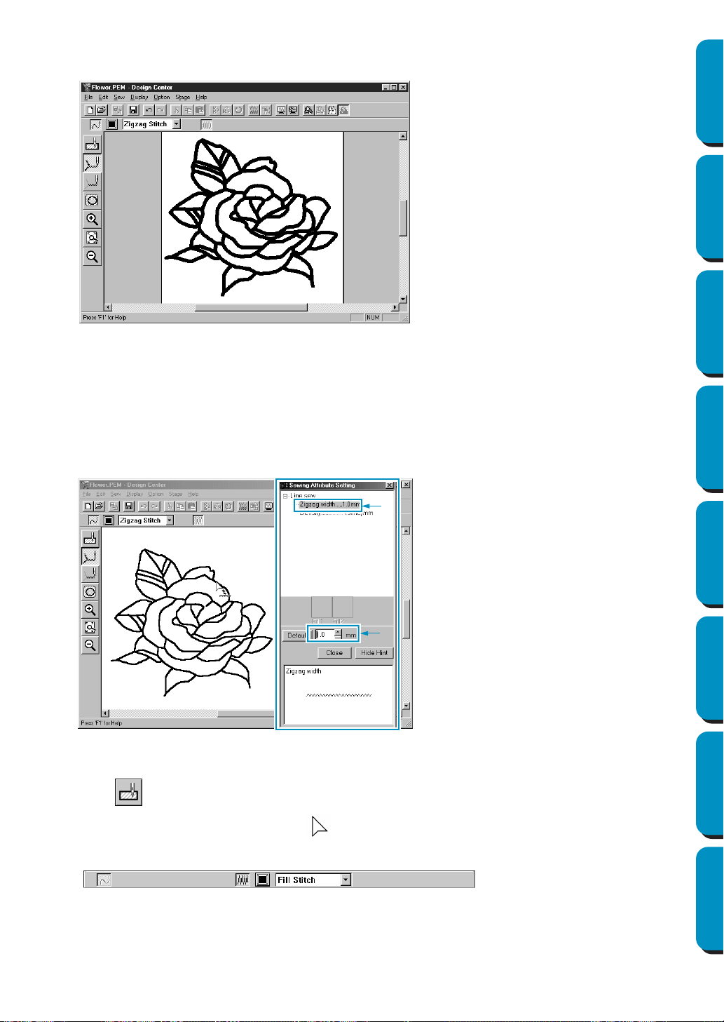
3 To set the stitch type: Click the Line sew type selector on the Sewing Attributes bar,
then click Zigzag Stitch.
4 To set the characteristics of the zigzag stitch, click Sew on the menu bar, then click Sewing
Attribute
on the submenu. You can also click the button of the Toolbar shown below.
The Sewing Attribute Setting dialog appears. The dialog displays the default settings for the line
stitch.
◆ Click the desired color if you want a
color other than black.
◆ Click Close only if you want to remove
the dialog from the screen.
◆ Place the cursor on the title bar; click
and drag the dialog box to a more con-
venient place on the screen.
◆ To change the width from 2.0 mm to
1.5 mm, for example, type or select
1.5
in the Zigzag width selector.
◆ Click
Close if you want to remove the
dialog from the screen.
25
Contents Before Using Getting Started Design Center Layout & Editing
Programmable
Stitch Creator
Quick Reference Alphabetic Index
5 Click on the outline of the pattern to apply the settings (color and stitch type) to the outlines.
Your image now looks like this:
If you think that the outline is still too thick, you can change it now.
6 To change the width of the outline: Click on the outline using the mouse’s right button.
The
Sewing Attribute Setting dialog displays.
Proceed in the same way as described in point 4 to change the Zigzag width from 1.5 mm to
1 mm.
7 Click on the outlines to apply the new setting.
Your image now looks like this:
■ Setting the regions
1
Click on the Tool Box.
The shape of the cursor changes to and is displayed together with a small rectangle.
The Sewing Attributes bar now looks like this:

26
Contents Before Using Getting Started Design Center Layout & Editing
Programmable
Stitch Creator
Quick Reference Alphabetic Index
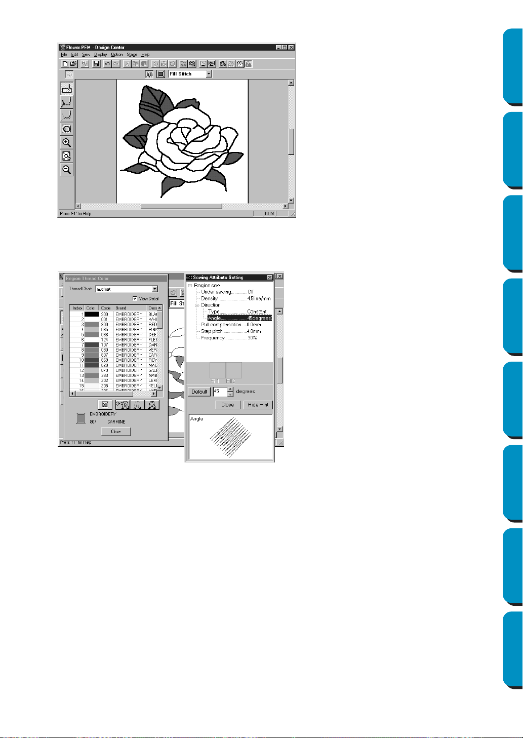
For the leaves:
Click the Region color button on the Sewing Attributes bar to display the Region Thread Color
dialog, then select the LEAF GREEN color.
The Region color button shows the selected color.
Click the Region sew type selector on the Sewing Attributes bar, then click Fill Stitch.
To set the characteristics of the fill stitch, click Sew on the menu bar, then click Sewing Attribute on
the submenu. You can also click the button of the Toolbar shown below.
The
Sewing Attribute Setting
dialog appears. The dialog displays the default settings for the region stitch.
◆ Set the direction of the fill stitch as explained in the “NOTE” below.
◆ Click on the regions of the leaves to which you want to apply a setting.
◆ Repeat the same operation for each stitch direction.
NOTE:
Using different directions for different regions can add contrast and improve the appearance of the
embroidery.
NOTE:
To be able to apply the sewing settings to a region, the region has to be closed. If you cannot apply
any setting to a given region, go back to the Figure Handle stage and make sure that region is closed.
Edit any faulty line with the Point Edit tool. For details on how to edit the figure handle image, see
“Point Edit Mode” on page 68.
Set the direction to 45˚ and click.
Set the direction to 90˚ and click. Set the direction to 135˚ and click.
27
Contents Before Using Getting Started Design Center Layout & Editing
Programmable
Stitch Creator
Quick Reference Alphabetic Index
After applying the sewing setting to the leaves, your image will look like this:
2 For one side of the petals:
Select the CARMINE color and set the direction, then click each region you want to apply the set-
tings to.
3 For the other side of the petals:
Select the RED color and set the direction, then click each region you want to apply the settings to.
28
Contents Before Using Getting Started Design Center Layout & Editing
Programmable
Stitch Creator
Quick Reference Alphabetic Index
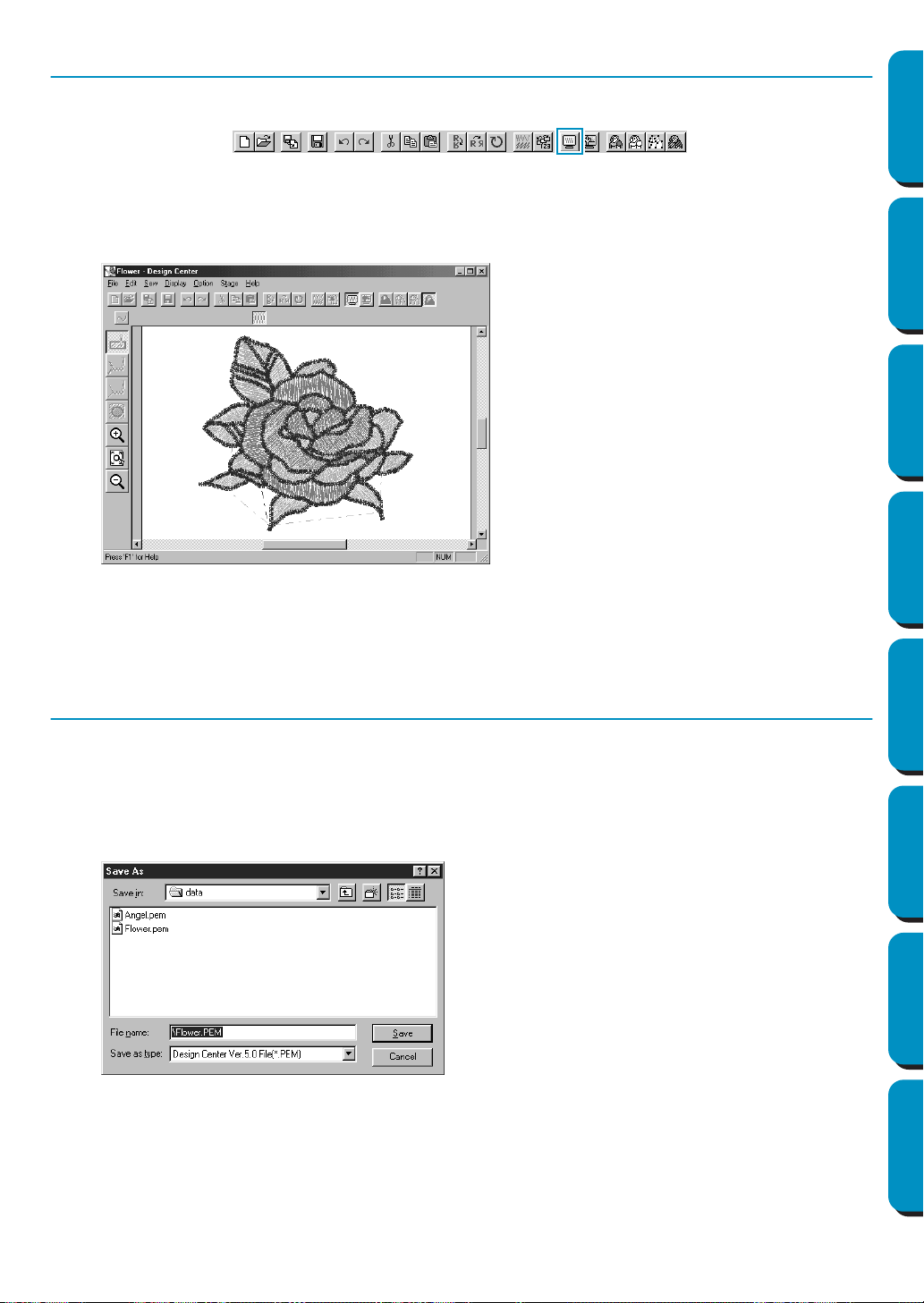
Step 8 Previewing the Image
To see how the pattern will look like once sewn, you can use the preview feature.
Toolbar:
Operation:
1 Click Display, then Preview.
You can also click on the button of the Toolbar shown above.
A preview of your embroidery pattern will appear.
2 To return to the normal working screen, click Display, then Preview or the Toolbar button again.
NOTE:
You cannot do any editing on the preview screen.
Step 9 Saving the File
This image will be used as the basis of a more complex embroidery picture. For that reason, we need to
save it.
1 Click File on the menu bar, then click Save As on the submenu.
This dialog displays.
NOTE:
To save the file under its default file name and in the same folder as the original file, you could use
Save instead of Save As.
If you did not save the line image data, you will be asked whether you want to save it as a
*.pel file.
◆ A default name
Flower.pem is dis-
played.
◆ If necessary, change the drive and
folder.
◆ Click Save to save the file.
29
Contents Before Using Getting Started Design Center Layout & Editing
Programmable
Stitch Creator
Quick Reference Alphabetic Index
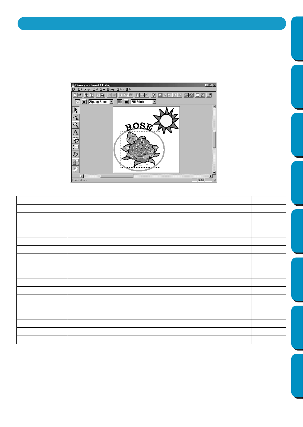
In this section, we are going to compose a complete embroidery file combining a pattern imported from
Design Center as well as patterns created with Layout & Editing, one of which we will apply a program-
mable stitch to.
The complete procedure will take you through the different steps of a normal working session with Layout
& Editing and will introduce you to some of its most important features.
At the end of this session, your embroidery picture will look like this:
Please follow these instructions step by step, in the sequence given. If you have to interrupt your training
for any reason, feel free to save the file (see Step 18). You will be able to retrieve it later and resume your
work.
Step 1 Starting Layout & Editing page 30
Step 2 Importing Embroidery Patterns from Design Center page 31
Step 3 Zooming In and Out page 32
Step 4 Moving the Embroidery Pattern page 35
Step 5 Adding an Oval page 36
Step 6 Adjusting the Size and Location of the Oval page 37
Step 7 Adding Text page 38
Step 8 Fitting the Text around the Oval page 40
Step 9 Moving the Oval and Text page 41
Step 10 Adding a Circle for Drawing the Sun page 41
Step 11 Selecting a Programmable Fill Stitch page 43
Step 12 Adding Broken Lines for Drawing the Sun Rays page 45
Step 13 Changing the Sewing Order of Sun and Rays page 46
Step 14 Adjusting the Rays page 46
Step 15 Setting Hole Sewing page 47
Step 16 Previewing the Sewing Image page 48
Step 17 Transferring the Data to a Card page 49
Step 18 Saving the File page 49
Using Layout & Editing
30
Contents Before Using Getting Started Design Center Layout & Editing
Programmable
Stitch Creator
Quick Reference Alphabetic Index
Step 1 Starting Layout & Editing
1 To start Layout & Editing, click the button, select Programs, then Version 5.0, and then click
Layout & Editing to open the Layout & Editing window.
You may also double-click the Layout & Editing icon in the program group.
The Layout & Editing window appears.
The window size will be smaller than the display area on the screen of your personal computer.
2 To make the Layout & Editing window fill up the available space on your screen, click the maximize
button on the right side of title bar.
If you are working with other programs, you can reduce the Layout & Editing window temporarily to
an icon by clicking the minimize button on the right side of title bar. You can then access the other
windows and icons on the display screen by using the mouse.
To return to the Layout & Editing window, click the icon.
NOTE:
If needed, you may change the Design Page properties at this point using the menu command
Option - Design Page Property, which will open the Design Page Property dialog. However, we will
leave the settings as is in this example.
If the shortcut icon for Design Center is
created, for example, on computer desk-
top, double-click it to start program.
Menu bar
Toolbar
Sewing attributes bar
Tool box
Work area
Design Page
Status bar
Maximize button
Close button
Title bar
Minimize button
31
Contents Before Using Getting Started Design Center Layout & Editing
Programmable
Stitch Creator
Quick Reference Alphabetic Index
Step 2 Importing Embroidery Patterns from Design Center
The first components of our embroidery picture will be a pattern imported from Design Center. If you
interrupted the exercise and closed the Design Center window, you will have to start the application
again and open the saved Flower.pem file again.
1 To start Design Center, click Option on the menu bar, then click Design Center on the submenu.
The Design Center window displays.
2 Click File on the Design Center menu bar, then click Open on the submenu.
An Open dialog similar to this will display.
3 The embroidery pattern appears on the Design Page of the Design Center application.
4 Click on the Layout & Editing window to bring it in the foreground of the screen.
5 Click File on the Layout & Editing menu bar, click Import on the submenu, then click from Design
Center
. You can also click the button of the Toolbar shown below.
◆ Select the drive, the folder and the file
name (
Flower.pem), then click Open.
• If the Preview check box is checked,
you may view your files in the Preview
window.
• Be sure to select a pem file saved in
stage 4. You cannot import another file
type from Design Center.
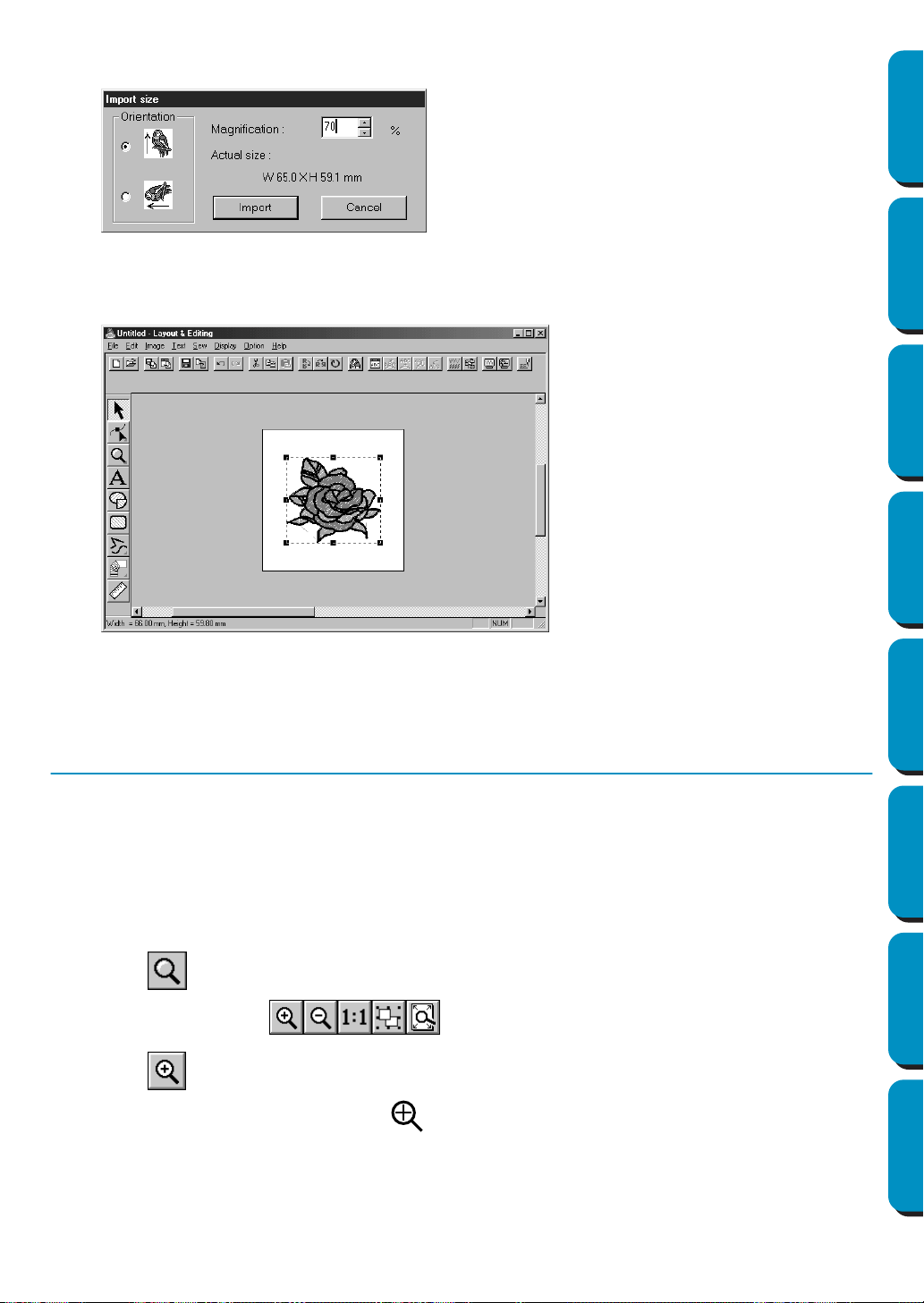
32
Contents Before Using Getting Started Design Center Layout & Editing
Programmable
Stitch Creator
Quick Reference Alphabetic Index
6 The Import Size dialog appears.
7 The embroidery pattern is imported into the Design Page of Layout & Editing.
The dotted line and the handles that appear around the image mean that the image is selected.
An imported image is always selected as a single object. It is not possible to select a part of an
imported image separately.
Step 3 Zooming In and Out
The quality of the display depends on the screen resolution of your computer. By default, the window is
set so that the entire Design Page is visible. If you need to work on a specific part of the Design Page,
you might wish to see a more detailed display of that part. This can be achieved by zooming in. When
you want to see the whole Design Page again, you can zoom out.
We are going to show how to zoom in on a portion of the picture and how to return to the standard dis-
play.
For a more complete description of the zoom features, see “Zoom Mode” on page 125.
1 Click on the Tool Box.
Five buttons appear: .
2 Click .
The shape of the cursor changes to .
◆ Select
70 %, for example.
◆ Leave the default orientation setting as
is.
◆ Click Import.
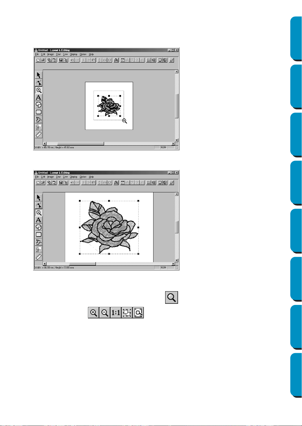
33
Contents Before Using Getting Started Design Center Layout & Editing
Programmable
Stitch Creator
Quick Reference Alphabetic Index
3 Drag the cursor across the area that you want to enlarge and click.
Alternatively, position the cursor at a corner of the rectangular area that you want to enlarge, then
click the mouse’s left button and keep the button down while moving the mouse toward the oppo-
site corner of the area. A dotted-line rectangle showing the selected area appears.
Release the mouse’s button when the dotted-line rectangle matches the area that you want to
enlarge. When you release the mouse’s left button, the selected area is enlarged.
The whole picture is enlarged at the same time. Repeat this procedure to enlarge the pattern even
more.
4 To display the image with its real dimensions, click on the Toolbar.
Five buttons appear: .
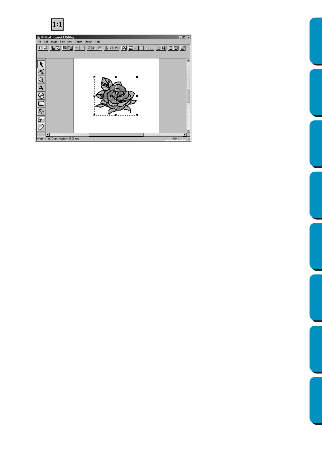
34
Contents Before Using Getting Started Design Center Layout & Editing
Programmable
Stitch Creator
Quick Reference Alphabetic Index
5 Click .
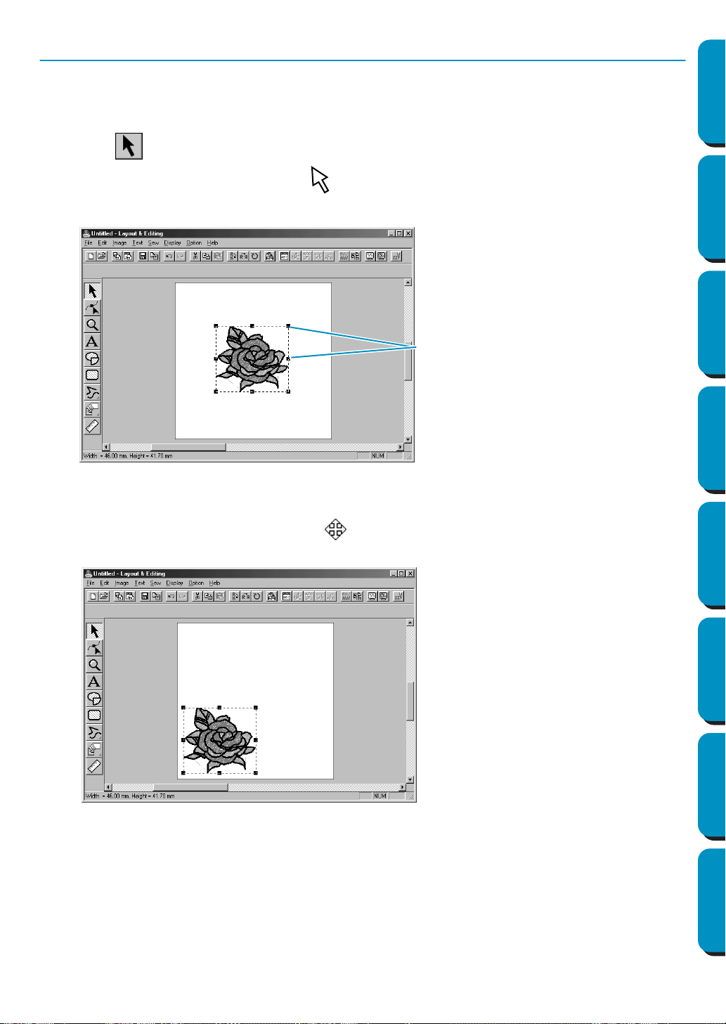
35
Contents Before Using Getting Started Design Center Layout & Editing
Programmable
Stitch Creator
Quick Reference Alphabetic Index
Step 4 Moving the Embroidery Pattern
When you import a pattern from Design Center, Layout & Editing puts the pattern at the center of the
Design Page. We are now going to see how to move the imported pattern to a different location.
1 Click on the Tool Box.
The shape of the cursor changes to .
2 Click the pattern.
The Status bar shows the dimensions (width and height) of the selected pattern.
3 Move the cursor over the selected pattern.
The shape of the cursor will change to .
You can now drag the pattern to another location.
Handles
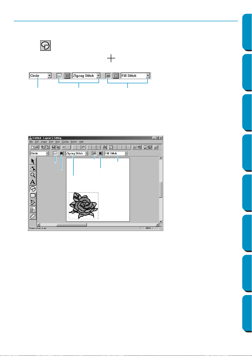
36
Contents Before Using Getting Started Design Center Layout & Editing
Programmable
Stitch Creator
Quick Reference Alphabetic Index
Step 5 Adding an Oval
The next component of our embroidery picture will be an oval. Since this oval will be used only as a guide
to fit text that we will add later, we must set it so that it is not sewn.
1 Click on the Tool Box.
The shape of the cursor changes to and displays together with a small ellipse. The Sewing
Attributes bar now looks like this:
If you keep the cursor for a while on a button or selector of the Sewing Attributes bar, a small label
indicating the function of the button will display.
The Arc shape selector allows you to select the shape of the pattern. For example, Circle is used to
draw circle and ellipses. The other options are used to draw circle-related patterns such as arcs.
For more details, see “Circle and Arc Drawing Mode” on page 128.
The Line stitch and Region stitch groups of buttons are for setting the stitch type and thread color
for the outline (Line stitch) and for the region inside (Region stitch).
If you click on the
Line sew button, the Line color button and the Line sew type selector disappear.
This means that the outline will not be sewn. To make the
Line color button and the Line sew type
selector reappear, click the Line sew button again.
2 Select the shape: Since the default shape is Circle, you don’t need to change the setting in the
Arc shape selector.
NOTE:
When drawing a circle or other circle-related pattern, you must always select the shape that you
want before drawing. You cannot, for example, draw a circle and change it to an arc afterward.
3 Disable the outline:
Click the Line sew button. The Line color and Line sew type buttons disappear
.
4 Disable the region inside: Click the Region sew button. The Region color and Region sew type
buttons disappear.
5 Draw the oval: Move the cursor to a point, click and drag.
As you drag, an outline of the oval is drawn. The final oval (outline and region inside) appears
when you release the mouse’s button.
Do not worry now about the position, size or aspect ratio (ratio between the height and width) of
the oval. We will adjust them later.
Arc shape
Line stitch
Region stitch
Line sew
Line color
Line sew type
Region sew
Region color
Region sew type
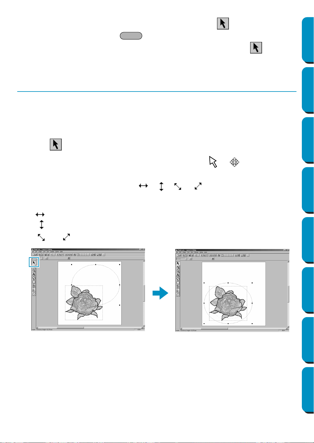
37
Contents Before Using Getting Started Design Center Layout & Editing
Programmable
Stitch Creator
Quick Reference Alphabetic Index
If, for any reason, you want to delete the oval and draw it again, click on the Tool Box, click on
the oval to select it, then press or click Edit – Delete on the menu bar.
If you wanted to attribute a color or a stitch type to the oval after drawing it, click on the Tool
Box, then click on the oval to select it and click on the
Line sew and Region sew buttons. The Sew-
ing Attributes bar for the oval will show the current settings and allow you to change them.
Step 6 Adjusting the Size and Location of the Oval
We are going to adapt the size and aspect ratio of the oval and move it to its final position.
■ To change the size of the oval
If your oval looks very different from the one shown in the illustration above, proceed as follows to
modify its size and proportions.
1 Click on the Tool Box.
2 Click the oval to select it. The shape of the cursor changes from to .
3 Move the cursor over one of the handles of the oval.
The shape of the cursor will change to , , or , depending on the handle the cur-
sor is on.
4 Drag the handle in the direction of the arrow to scale the pattern.
is for scaling the width.
is for scaling the height.
and are for scaling both dimensions at the same time.
Delete

38
Contents Before Using Getting Started Design Center Layout & Editing
Programmable
Stitch Creator
Quick Reference Alphabetic Index
■ To center the oval on the pattern
If your oval is not well centered, on the pattern, proceed as follows to move it.
1 Click on the Tool Box.
The shape of the cursor changes to .
2 Click the oval to select it.
3 Move the cursor over the oval.
The shape of the cursor will change to .
4 You can now drag the oval to its final location.
Step 7 Adding Text
The next component of our embroidery picture is a piece of text.
1 Click on the Tool Box.
The shape of the cursor changes to and this appears on the Sewing Attributes bar:
2 Set the text color: You can set the text color at this step. For this example, we are not going to
change the default black color.
3 Set the font: You can set the font at this step. For this example, we are not going to change the
default font, but if you click on the
Font selector, you can scroll through the many different font
styles available.
4 Set the text size: Click on the Text size selector and select the desired size of the characters (for this
example, we will keep the default size of
10.0 mm). The value indicates the height of the characters.
Text color
Font
Text size Text sew type
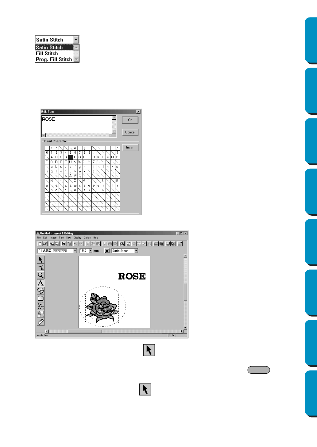
39
Contents Before Using Getting Started Design Center Layout & Editing
Programmable
Stitch Creator
Quick Reference Alphabetic Index
5 Set the text stitch: Click on the Text sew type selector and select the desired stitch for the text. For
this example, we will keep the default stitch
Satin stitch.
For more precise setting of the text attributes, see “Text Attribute Setting” on page 198.
6 Enter the text: Click anywhere in the Design Page. The actual location does not matter, because
we can move the text after creating it.
The
Edit Text dialog displays.
The text appears on your Design Page when you click OK.
If you want to edit the entered text, click on the Tool Box, then click on the text to select it and
click
Text – Edit Text Letters on the menu bar to open the Edit Text dialog. You may then edit your
text as necessary. If you simply wanted to delete the text, select it, then press .
If you want to change the text color, font or other attributes after entering the text, you can do so
while in the text mode or after clicking on the Tool Box, and selecting the text. The Sewing
Attributes bar for the text pattern will show the current settings and allow you to change them.
◆ Type your text (“ROSE”, for example).
◆ You can also enter a character by clicking
it on the character table, then clicking
Insert or simply by double-clicking it. This
is specially useful if you have to enter
accented characters that are not avail-
able on your keyboard.
◆ Click OK to confirm.
◆ Click Cancel to exit.
Delete

40
Contents Before Using Getting Started Design Center Layout & Editing
Programmable
Stitch Creator
Quick Reference Alphabetic Index
Step 8 Fitting the Text around the Oval
We are going to fit the text around the oval.
1 Click on the Tool Box to set the cursor in selection mode .
2 Click the text to select it.
3 Press the key and hold it down while clicking on the oval.
This allows you to select the oval without deselecting the text.
4 Click Text on the menu bar, then click Fit Text to Path Setting on the submenu.
You can also click the button of the Toolbar shown below.
This dialog appears.
◆ Click OK without changing any setting.
• For more details about this setting, see “Fit
Text to Path Setting” on page 199.
Ctrl
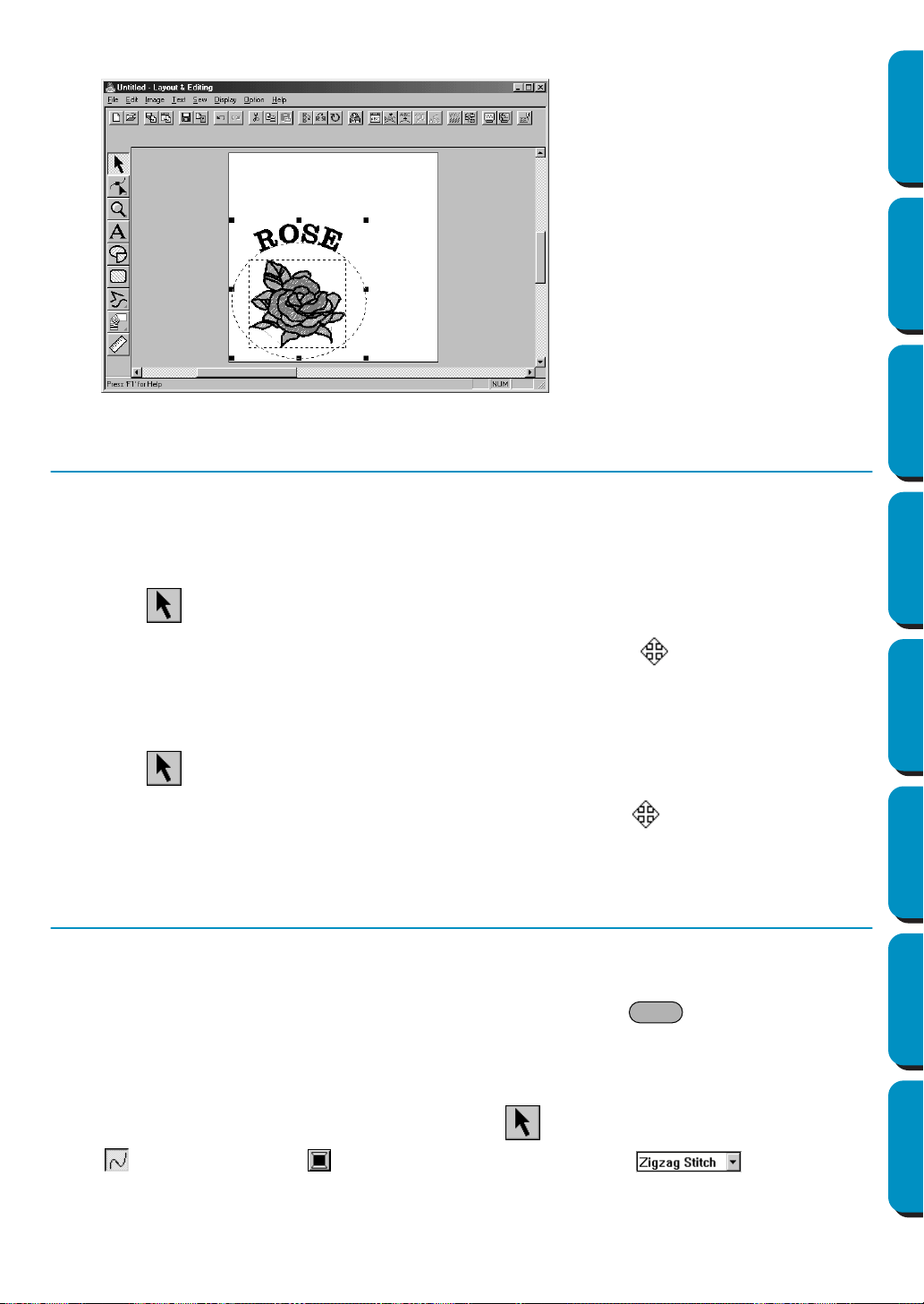
41
Contents Before Using Getting Started Design Center Layout & Editing
Programmable
Stitch Creator
Quick Reference Alphabetic Index
5 Your text now fits nicely on the oval.
Step 9 Moving the Oval and Text
Once the text is fit to the oval, you can move both patterns as a group, without affecting their relative
position, or you can move the text alone to change its position on the oval.
■ To move both patterns as a group
1
Click on the Tool Box, then click on the oval to select it.
2 Move the cursor over the oval, to change the shape of the cursor to .
3 Drag the oval: The text moves together with the oval.
■ To move the text over the oval
1
Click on the Tool Box, then click on the text to select it.
2 Move the cursor over the text to change the shape of the cursor to .
3 Drag the text: The text can only move along the oval.
Step 10 Adding a Circle for Drawing the Sun
The next component will be a sun. We will first draw a circle to get the basic shape.
1 Draw a circle.
To draw a circle, proceed as you did to draw the oval, but hold the key down while drag-
ging.
If you need to modify the size of the circle, drag a handle at one of the corners.
2 Set the stitch color and type of the outline.
To do this, you must first select the circle using the button. Next, click on the
Line sew button
so that the Line color button and the Line sew type selector appear and
select a line color and stitch.
Shift
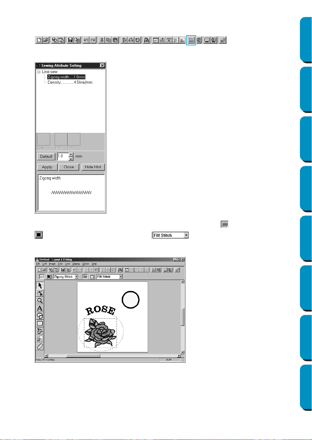
42
Contents Before Using Getting Started Design Center Layout & Editing
Programmable
Stitch Creator
Quick Reference Alphabetic Index
3 Set the sewing attributes of the outline stitch.
Select
Sew – Sewing Attribute Setting. You can also click the button of the Toolbar shown below.
The Sewing Attribute Setting dialog opens.
4 Set the sewing attributes of the region. Click on the Region sew button so that the Region color
button and the Region sew type selector appear and select a region color and a
stitch. In this example, we will leave the other sewing attributes of the region as is.
Your display will look as follows.
◆ Set the width of the zigzag stitch to
1.0 mm.
◆ Click Apply.
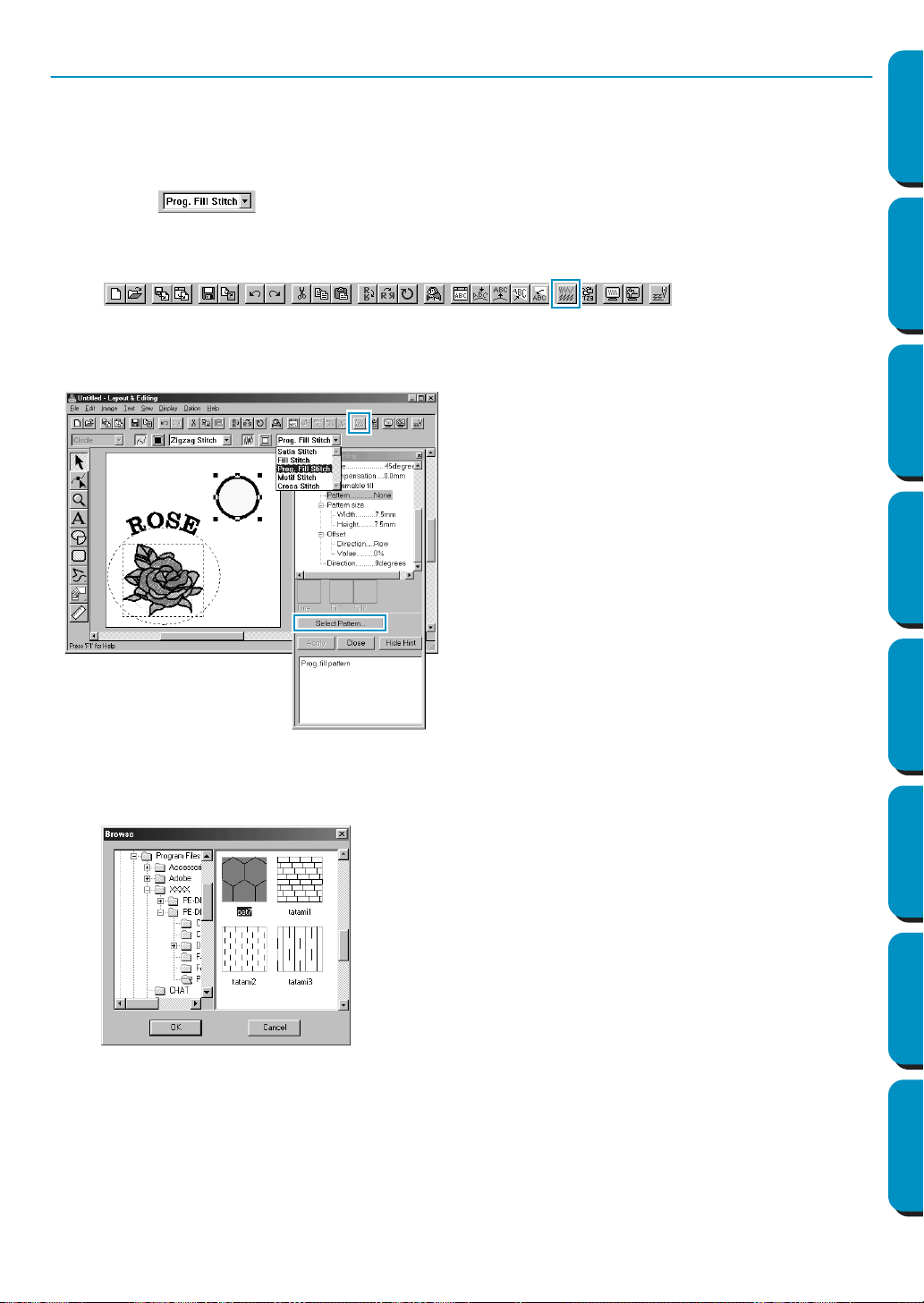
43
Contents Before Using Getting Started Design Center Layout & Editing
Programmable
Stitch Creator
Quick Reference Alphabetic Index
Step 11 Selecting a Programmable Fill Stitch
You are going to see how to select a special stitch pattern (fill stitch) created with the Programmable
Stitch Creator application, how to change its settings and how to apply it as the region stitch for the rays,
which you will draw in Step 12. Stitch patterns are arranged in a tile-like manner within the selected
regions, creating very decorative fill stitches.
1 Select in the Region sew type selector.
2 Click Sew – Sewing Attribute Setting on the menu bar to open the Sewing Attribute Setting dialog.
You can also click on the Toolbar button shown hereafter.
3 Change the stitch pattern size. Select a width and height of 10.0 mm (3/8 inch) by clicking on the
“up” arrow.
NOTE:
As soon as you click an arrow in this dialog, an illustration of the stitch pattern as well as the type
of setting you are selecting are displayed in the other preview window of the dialog. You can see
how each click on an arrow affects the pattern.
You may also type in a value. In that case however, you cannot preview the setting immediately as
you set it.
◆ Select Pattern in the Programmable Fill cate-
gory.
◆ Click Select Pattern to open the Browse dialog.
◆ Select the path Program Files/Version 5.0/Pat-
tern.
The Pattern folder contains the programmable
stitch files. These files have the extension pas.
The Browse dialog shown hereafter now allows
you to preview and browse through the existing
pas files.
Note:
“*.pas” files are patterns for Programmable Fill.
“*.pmf” files are patterns for Motif.
◆ Browse through the illustrated stitches and
click on the pat 7 illustration, which is then
highlighted.
◆ Either double-click the illustration or click OK to
select that stitch. The dialog closes and the
selected stitch can now be previewed in the
Sewing Attribute Setting dialog.

44
Contents Before Using Getting Started Design Center Layout & Editing
Programmable
Stitch Creator
Quick Reference Alphabetic Index
4 Change the row offset. Under the Offset category, set the Direction as Row and set the value at
“50%”, and holding the mouse button down on either arrow or by typing the value directly in the
edit box window.
NOTE:
You can only choose to change either the row or the column offset for a given pattern. You cannot
select both for the same stitch pattern.
5 Change the direction of the pattern. Rotate the pattern to the right by clicking on the “down” arrow
until a value of
340 degrees is selected. The Sewing Attribute Setting dialog will look like this:
• For more information on the different settings of a programmable stitch, see “Sewing Attribute
Setting” on page 204.
6 Click Apply.
The stitch and its settings are set. Until they are changed again, those sewing settings, just like
any other, will be applied to every new region that you draw.
7 Finish setting the remaining sewing attributes for the ray pattern that you will create in the following
step.
Select a region color using the Region color button.
8 Select a line color and stitch using the Line color button and the Line sew type selector
. (You can also set the characteristics of the pitch in the Line sewing tab of the Sew-
ing Attribute Setting
dialog.)
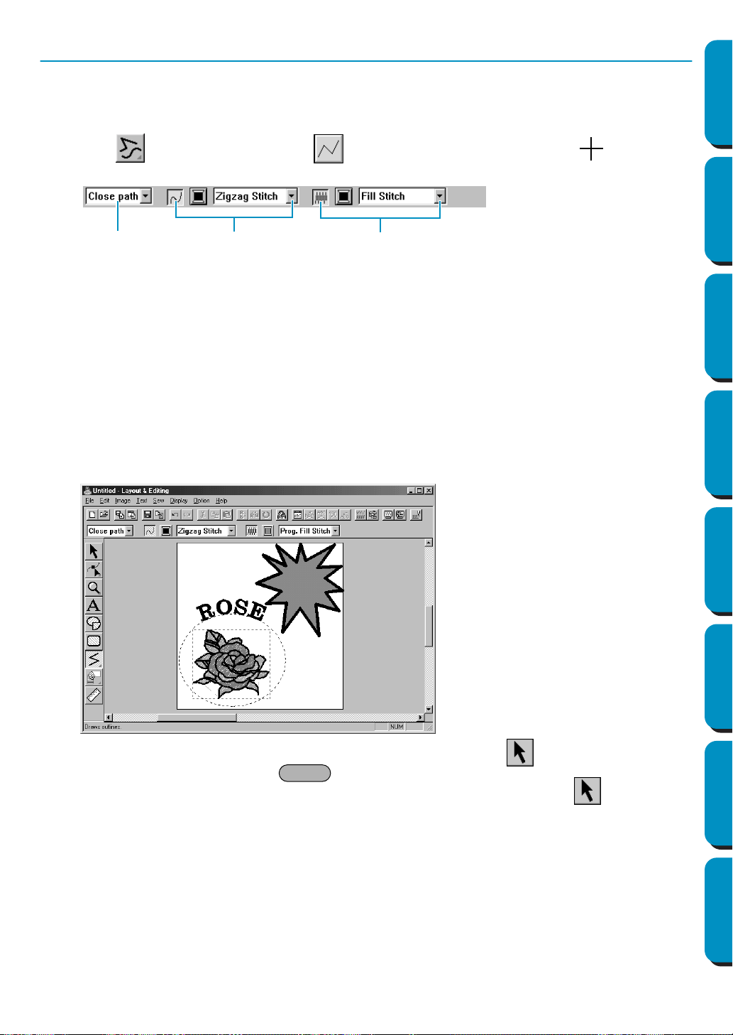
45
Contents Before Using Getting Started Design Center Layout & Editing
Programmable
Stitch Creator
Quick Reference Alphabetic Index
Step 12 Adding Broken Lines for Drawing the Sun Rays
Let’s draw a few rays around the sun. There are, of course, many ways to do this. You could, for example,
draw a single straight line for each ray. Here, we are going to use a closed polygonal line (broken line) to
make all the rays in one star-like pattern.
1 Click on the Tool Box, then click . The shape of the cursor changes to and displays
together with a miniature image of the tool button. The Sewing Attributes bar now looks like this:
2 Be sure Close path is selected in the Path shape selector.
When drawing a closed path, the first point and the last point are automatically joined. The pattern
has an outline and a region and you can apply sewing settings to both.
With an open path, the broken line is left open (the first and last point are not automatically joined).
The pattern will not have a region, thus you can only apply sewing settings to the outline.
3 Draw the broken line around the circle using the circle as a guide.
Move the mouse to the starting point and click. Move the mouse to the end point of the first straight
line and click again.
NOTE:
You can always remove the last-entered point by clicking the mouse’s right button.
4 Repeat until you arrive at the last ending point. At that point double-click. As soon as you have
double-clicked, the display will look like the following.
If, for any reason, you want to delete the pattern and draw it again, click on the Tool Box, click on
the pattern to select it, then press or click
Edit – Delete on the menu bar.
If you want to change the pattern path shape, color, or stitch after drawing it, click on the Tool
Box, then click on the pattern to select it. Then change the settings at the Sewing Attributes bar or the
Sewing Attribute Setting dialog.
Now that the rays are drawn, you might want to have a quick preview of the programmable stitch pattern
at this stage and come back to this exercise later. To see how to preview an embroidery pattern, refer to
Step 16 “Previewing the Sewing Image”.
Path shape
Line stitch
Region stitch
Delete
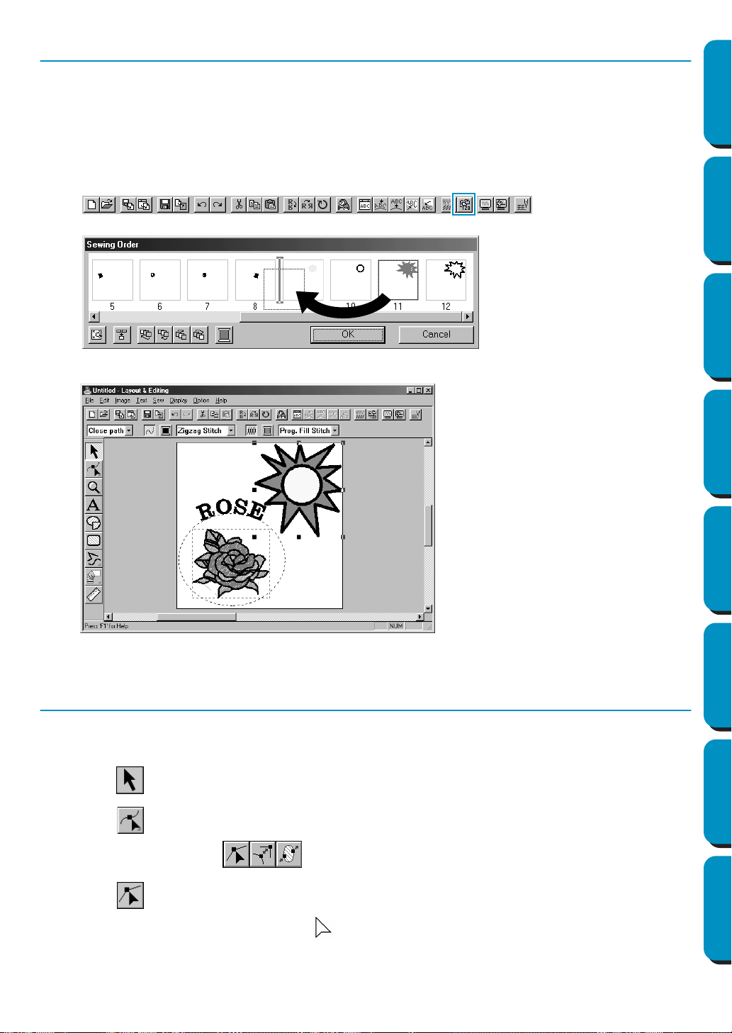
46
Contents Before Using Getting Started Design Center Layout & Editing
Programmable
Stitch Creator
Quick Reference Alphabetic Index
Step 13 Changing the Sewing Order of Sun and Rays
Since we have drawn the broken line after drawing the circle, the broken line pattern is in the foreground
of the screen, and the circle is behind. A pattern that is in the foreground of the screen is sewn last. Since
we do not want the embroidery to show the part of our broken line that is inside the circle of the sun, we
are going to reverse the sewing order.
1 Click Sew on the menu bar, then click Sewing Order on the submenu.
You can also click on the Toolbar button shown hereafter.
This will move the ray pattern to the back of the circle.
If necessary, move the circle so that it looks centered relative to the ray pattern.
Step 14 Adjusting the Rays
At this step you might wish to modify the rays. You can do that by moving, deleting and adding points on
the broken line pattern.
1 Click on the Tool Box and select the ray pattern.
2 Click on the Tool Box.
Three buttons appear: .
3 Click .
The shape of the cursor changes to and the existing points of the pattern are marked with
small empty squares.
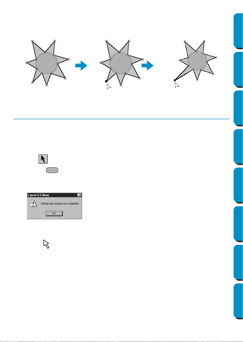
47
Contents Before Using Getting Started Design Center Layout & Editing
Programmable
Stitch Creator
Quick Reference Alphabetic Index
4 Click the point that you want to move.
The selected point is marked with a small black square.
5 Drag the point to a new position.
The point remains selected, so that you can drag it again.
To add or delete a point, see “Inserting points” on page 121 and “Deleting points” on page 122.
Step 15 Setting Hole Sewing
If the sun is sewn according to the current setting, the complete broken line for the rays will be sewn first,
then the circle will be sewn on top of the pattern of the rays. To avoid sewing twice at the same place, you
can set the pair of patterns (circle and broken line) for hole sewing. This way, the part of the rays that is
hidden behind the circle will not be sewn.
1 Click on the Tool Box, then click on the sun’s circle to select it.
2 Hold the key down and click on the sun’s rays.
The circle and the broken line are now selected together.
3 Click Sew on the menu bar, then click Set Hole Sewing on the submenu. This message displays:
When a pair of patterns are set to hole sewing, they cannot be moved separately. If you need to
readjust their relative position, you must first select the circle or the broken line with the selection
cursor , then release the hole sewing setting by clicking Sew on the menu bar, then Cancel
Hole Sewing
.
NOTE:
The Hole Sewing setting is not possible if one of the patterns in the pair is not completely inside the
other pattern.
◆ Click
OK to remove the message.
3
4
5
Ctrl
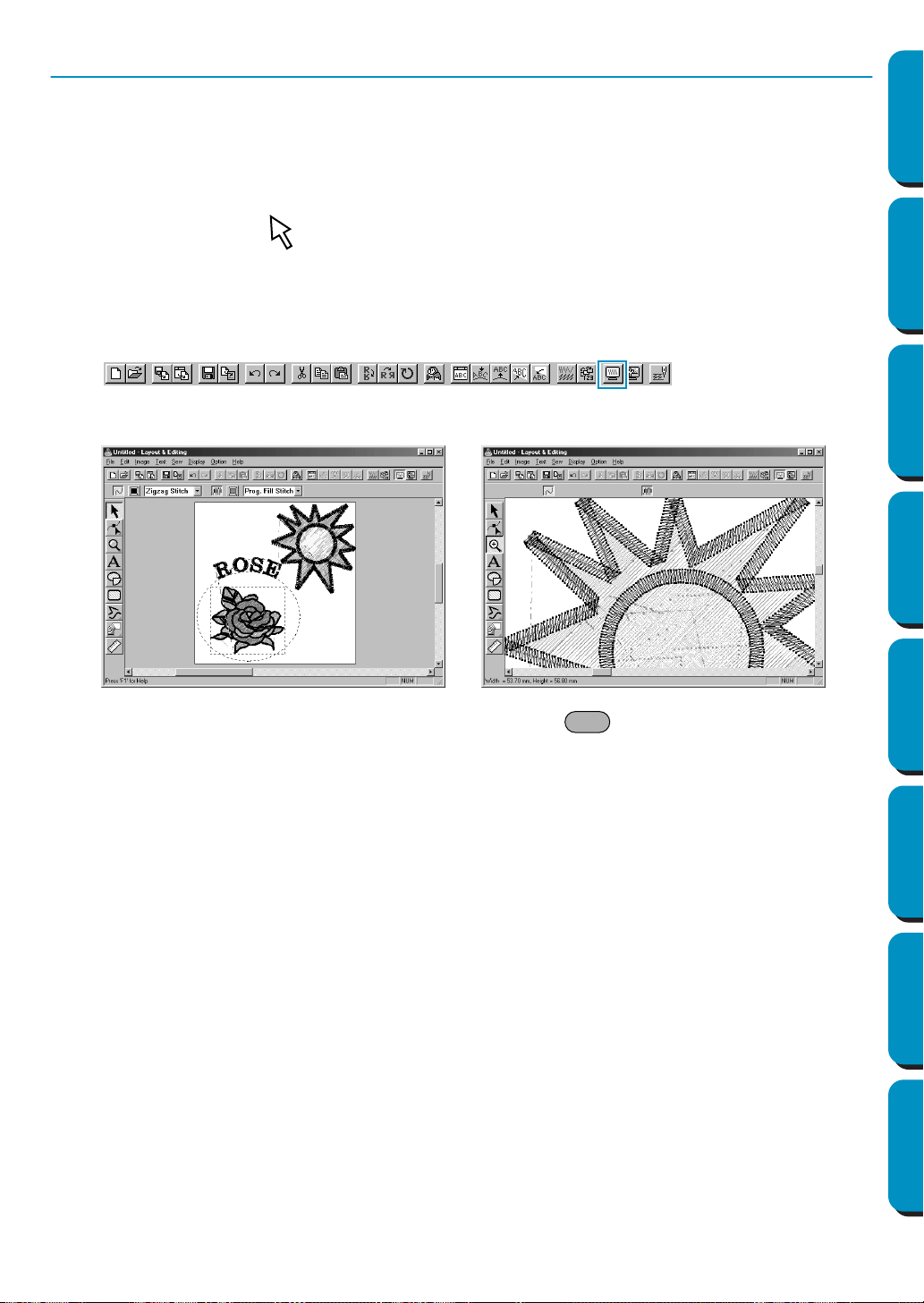
48
Contents Before Using Getting Started Design Center Layout & Editing
Programmable
Stitch Creator
Quick Reference Alphabetic Index
Step 16 Previewing the Sewing Image
Our embroidery image is now complete. You can preview it to have a more realistic view of how it will look
once sewn. The preview function also shows how sewing will actually proceed. For example, you will be
able to see clearly that the part of the broken line that is behind the circle is not sewn and how the
selected programmable stitch fills the rays.
1 To preview the entire embroidery picture, deselect everything by clicking on the white space with
the selection cursor .
To preview a single pattern, or a group of patterns, select the pattern(s).
To preview a region for which you selected programmable stitch pattern, select it and zoom in on it.
2 Click Display on the menu bar, then click Preview on the submenu.
You can also click on the button of the Toolbar shown below:
The preview display will appear.
3 To return to the normal display, repeat step 2 or press the key.
NOTE:
You cannot do any editing on the preview screen.
Esc
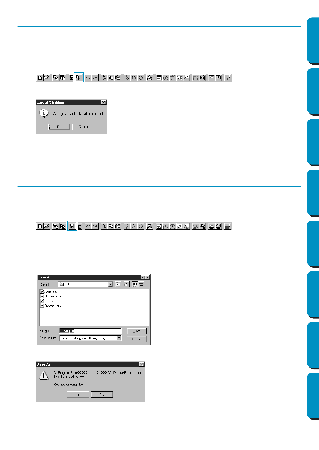
49
Contents Before Using Getting Started Design Center Layout & Editing
Programmable
Stitch Creator
Quick Reference Alphabetic Index
Step 17 Transferring the Data to a Card
Before you can actually sew your embroidery pattern, you must transfer it to an Original card.
1 Insert an Original card in the module.
2 Click File on the menu bar, then click Write to Card on the submenu.
You can also click on the button of the Toolbar shown below:
This dialog will display.
If the card module is not correctly connected or powered, if the card is not inserted or is defective,
you will see an error message. Refer to “Write to Card – Current Design” on page 157 for more
details.
Step 18 Saving the File
Before quitting the application, you should save your file on disk to be able to retrieve it later.
1 Click File on the menu bar, then click Save on the submenu.
You can also click on the button of the Toolbar shown below:
If the file already exists on the disk (the file has been saved at least once), the file is saved imme-
diately.
2 If the file name is still Untitled or if, for any other reason, the file cannot be found on the disk, the
application will ask you to enter a file name and select a target folder.
If the new file name already exists, this dialog will appear:
The new file name displays in the title bar of the Layout & Editing window.
◆ If the card is not brand new, make sure
that you want to erase the data that is
already stored on the card and click
OK.
◆ Click Cancel to exit.
◆ Select the drive, the folder and type the
file name.
◆ Click
Save to save.
◆ Click Cancel to exit.
◆ Click Yes to overwrite.
◆ Click
No if you do not want to overwrite
the existing file. You can then enter
another file name.
50
Contents Before Using Getting Started Design Center Layout & Editing
Programmable
Stitch Creator
Quick Reference Alphabetic Index
This application allows you to design your own fill stitch patterns, which you can set as sewing attributes
to enclosed regions of patterns, both in Design Center and Layout & Editing. The stitch patterns fill the
regions in a tile-like manner, resulting in particularly decorative embroidery patterns. You may create your
own fill stitch patterns or use the many stitches delivered with this application with or without editing
them.
In this exercise, you are going to see how to edit an existing stitch pattern.
The complete procedure will take you through the different steps of a normal working session with Pro-
grammable Stitch Creator and will introduce you to its most important features.
Please follow these instructions step by step, in the sequence given. If you have to interrupt your training
for any reason, feel free to save the file (see Step 4). You will be able to retrieve it later and resume your
work.
Step 1 Starting Programmable Stitch Creator page 51
Step 2 Opening a Programmable Stitch File page 52
Step 3 Drawing Lines to Edit the Programmable Stitch page 53
Step 4 Saving the Edited Programmable Stitch page 54
Step 5 Quitting Programmable Stitch Creator page 54
Using Programmable Stitch Creator
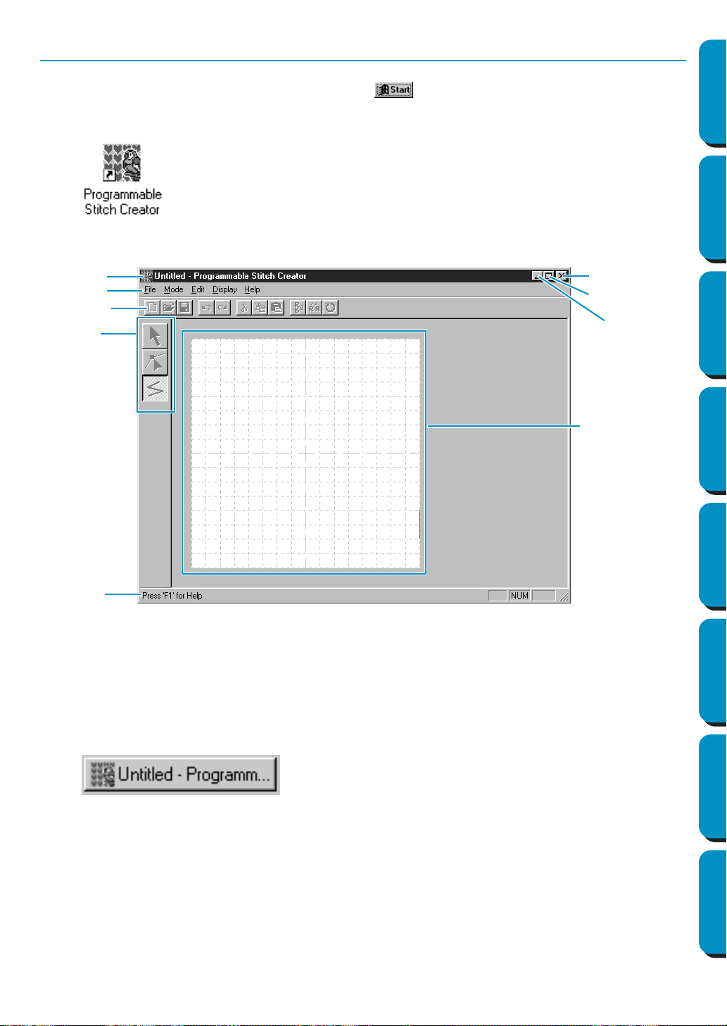
51
Contents Before Using Getting Started Design Center Layout & Editing
Programmable
Stitch Creator
Quick Reference Alphabetic Index
Step 1 Starting Programmable Stitch Creator
1 To start Programmable Stitch Creator, click the button, select Programs, then Version 5.0,
and then click Programmable Stitch Creator to open the Programmable Stitch Creator window.
You may also double-click the Programmable Stitch Creator icon in the program group.
The Programmable Stitch Creator window displays.
The window size will be smaller than the display area on the screen of your personal computer.
2 To make the Programmable Stitch Creator window fill up the available space on your screen, click
the maximize button on the right side of title bar.
If you are working with other programs, you can reduce the Programmable Stitch Creator window
temporarily to an icon by clicking the minimize button on the right side of title bar. You can then
access the other windows and icons on the display screen by using the mouse.
To return to the Programmable Stitch Creator window, click the icon.
If the shortcut icon for programmable stitch
creator is created, for example, on com-
puter desktop, double-click it to start pro-
gram.
Menu bar
Toolbar
Tool box
Work area
Status bar
Close button
Maximize button
Minimize butto
n
Title bar
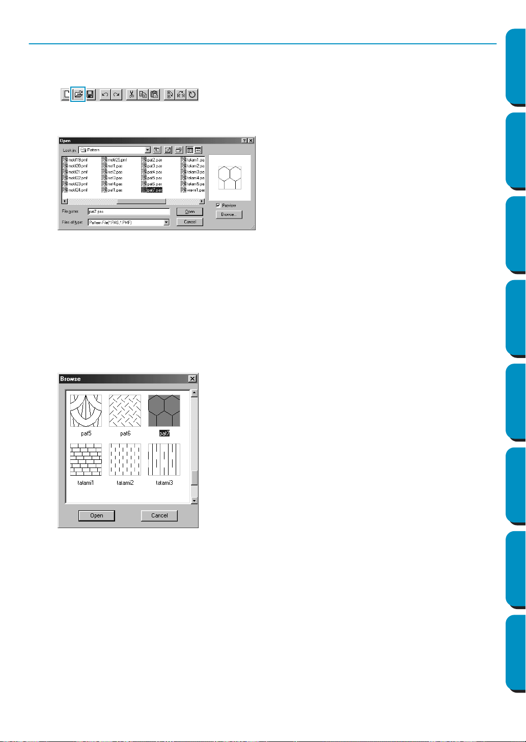
52
Contents Before Using Getting Started Design Center Layout & Editing
Programmable
Stitch Creator
Quick Reference Alphabetic Index
Step 2 Opening a Programmable Stitch File
1 Click File on the menu bar, then click Open on the submenu.
You can also click on the Toolbar button shown below.
The Open dialog opens.
The Browse dialog opens.
NOTE:
You will create a pattern for Programmable Fill
here.
If you know which file you want to open:
◆ Select a pas file in the Pattern folder by click-
ing on it.
The contents of the selected file displays in
the
Preview window, provided its check box
is checked.
◆ Double-click the selected
pas file or click
Open to open the file.
If you want to scroll through the available files
before opening one:
◆ Click Browse to preview all the available pas
files in the selected folder.
◆ Browse through the files with the help of the
scroll bar.
◆ Select a stitch pattern by clicking on it. The
selected pattern is highlighted.
◆ Double-click the selected pattern or click
Open to open the file and to close both the
Open and the Browse dialogs.
NOTE:
“*.pas” files are patterns for Programmable Fill.
“*.pmf” files are patterns for Motif. Use the
Mode menu to change the type of file to create.
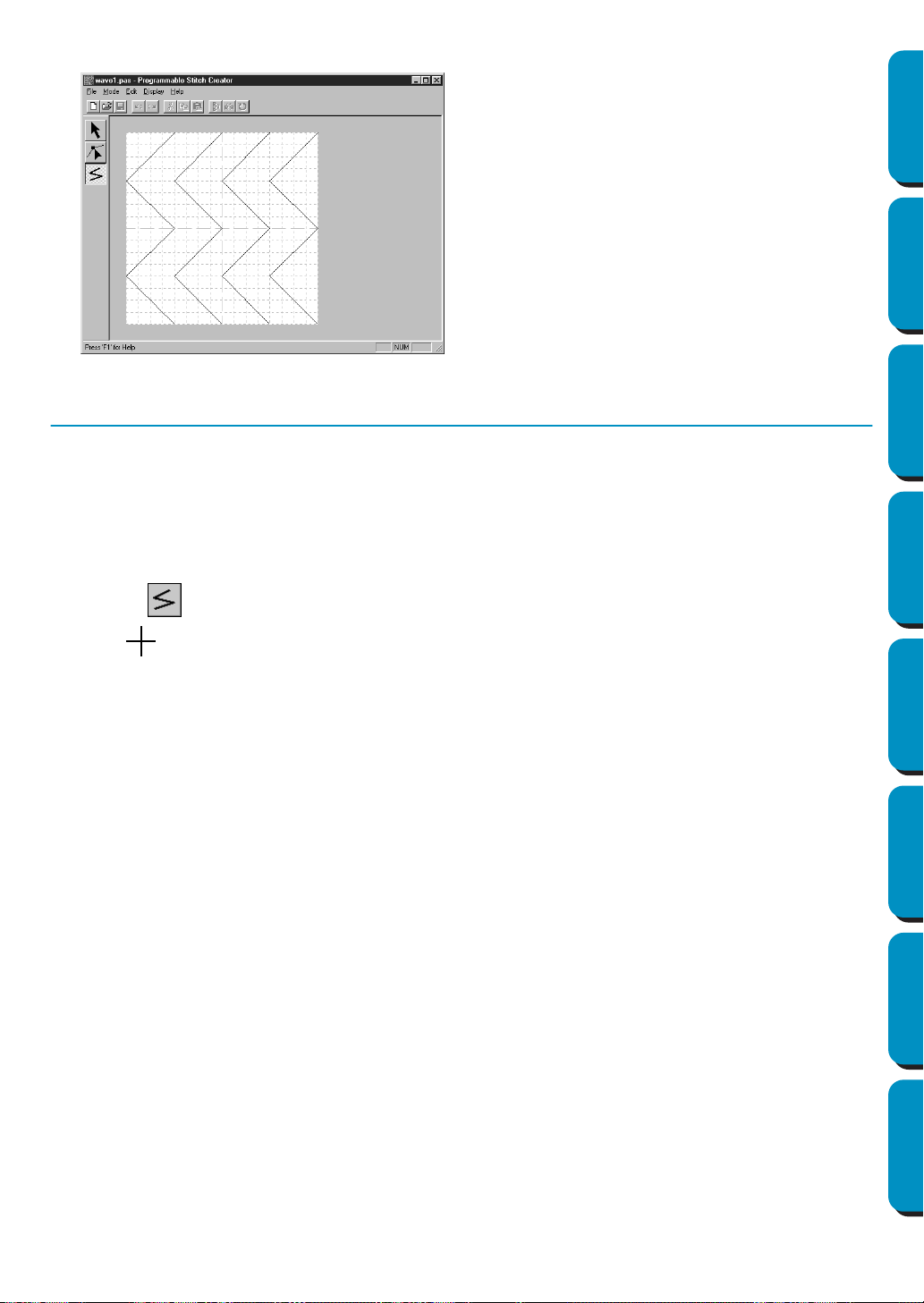
53
Contents Before Using Getting Started Design Center Layout & Editing
Programmable
Stitch Creator
Quick Reference Alphabetic Index
The stitch pattern displays on the work area of the Programmable Stitch Creator application.
Step 3 Drawing Lines to Edit the Programmable Stitch
We are going to draw a wave between the displayed ones using the Line drawing tool of the Tool Box.
To draw these waves, we will use the grid setting medium with which the pes file stitch pattern was saved.
NOTE:
Grid types should be selected according to the details you want to draw. Select a narrower grid for
more detailed stitches and a wider grid for more simple ones.
For more information on the grids and on how to select them, refer to “Grid” on page 248.
1 Click on the Tool Box. Move the cursor over the work area. The shape of the cursor changes
to and displays together with a miniature illustration of the tool button.
2 Move the mouse to the second vertical grid line following a wave and click.
NOTE:
The horizontal and vertical lines that you draw on the work area always follow the grid. The points
you create by clicking the mouse are inserted at the intersection of the horizontal and vertical lines
of the grid, enabling you to draw diagonal lines as well. So, regardless on where you click, a point
will automatically be inserted at the nearest intersection.
3 Move the mouse to the first angle and click again.
NOTE:
You can always remove the last-entered point by clicking the mouse’s right button.
4 Repeat until you reach the end of the line and double-click.
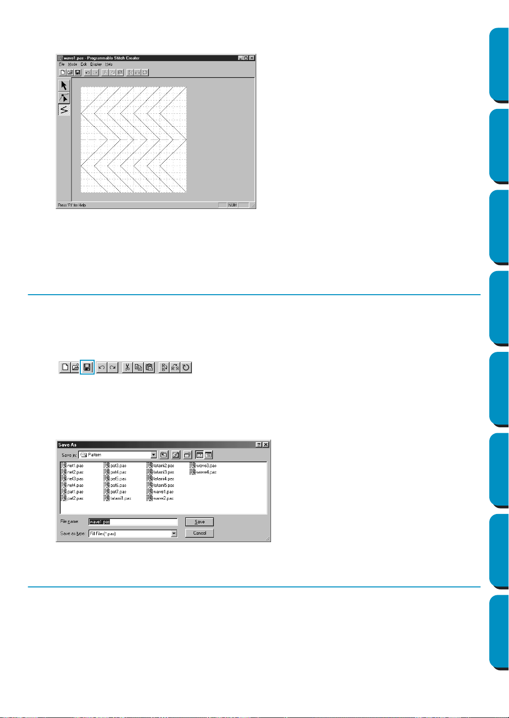
54
Contents Before Using Getting Started Design Center Layout & Editing
Programmable
Stitch Creator
Quick Reference Alphabetic Index
5 Repeat the procedure to add two more waves.
Your display may look somewhat like the following.
If you want to edit some points of the pattern that you drew, you can do so in the Point edit mode,
which you were introduced to in the Layout & Editing window. The Point edit mode lets you move,
insert and delete points (see “Point Edit Mode” on page 235 or go back to Step 14 “Adjusting the
Rays” on page 46).
Step 4 Saving the Edited Programmable Stitch
In order to apply your edited stitch pattern to a region in Layout & Editing or Design Center, you must first
save it as a pas file. To do this, proceed as follows.
1 Click File on the menu bar, then click Save on the submenu.
You can also click on the button of the Toolbar shown below:
Since the pas files that come with your program are “Read Only” files and cannot be overwritten,
the Save as dialog opens.
2 Type in a file name and select another target folder if you want to save your own stitch pattern files
separately.
Step 5 Quitting Programmable Stitch Creator
Now that you have created a stitch pattern, you may close this application as you will no longer need it for
this exercise.
1 Click File on the menu bar, then click Exit on the submenu.
If you have saved your file as recommended in the previous step, the application will close immedi-
ately. If you have changed anything after the last time you saved the file, you will be asked whether
you want to save the file. Click
Yes, then proceed as explained in the previous step.
◆ Select the drive, the folder and type the
file name.
◆ Click Save to save.
◆ Click Cancel to exit.
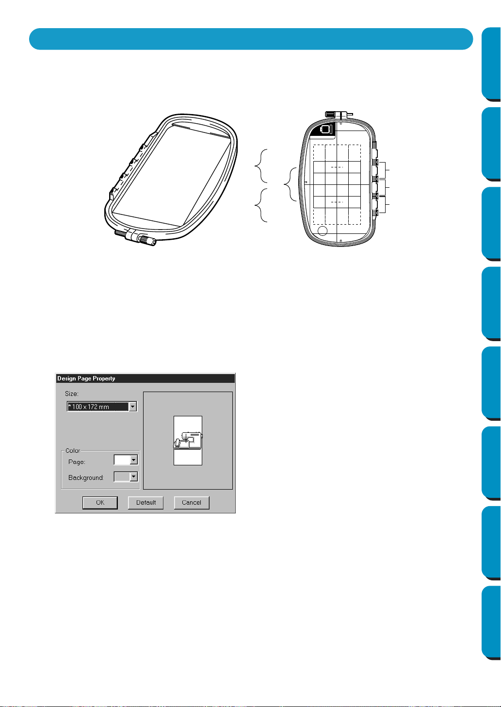
55
Contents Before Using Getting Started Design Center Layout & Editing
Programmable
Stitch Creator
Quick Reference Alphabetic Index
By attaching the enclosed (or optional) multi-position frame (130 × 300 mm or 100 × 172 mm) at each of
its three installation positions, multi-position designs can be embroidered.
With this program you will be able to create designs that you can stitch in any multi-position hoop.
(Jumbo Hoop and Extra Large Hoop)
Although the size of the pattern that can be embroidered using an multi-position frame is 130 × 180 mm
(or 100 × 100 mm, depending on the sewing area of the embroidery machine), first determine which of
the three installation positions (indicated as a, b, and c in the illustration above) the multi-position frame
will be installed at and determine the orientation of the data.
When creating the pattern, each design section can only be as large as the sewing field of the machine.
■ Select the Design Page size
1
In Layout & Editing, click Option, then Design Page Property.
NOTE:
The Design Page size in dialog shown above is not available in Design Center since the maximum
sizes for a single pattern are 260
×
160 mm, 130
×
180 mm, and 100
×
100 mm. Remember that
260
×
160 mm size cannot be used for a multi-position frame.
◆ From the
Size selector, choose a
Design Page size of 130 × 300 mm,
300 × 130 mm, 100 × 172 mm, or 172 ×
100 mm.
(Settings for multi-position frames are
indicated by “*”.)
• Choose the appropriate setting after
checking the size of the embroidery
frame available for your machine.
Creating data for the multi-position frame
a
b
c
a
b
c
ABC
Example of Multi-Position Frame: 100 × 172 mm embroidery frame
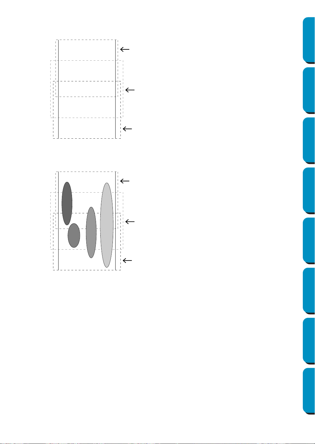
56
Contents Before Using Getting Started Design Center Layout & Editing
Programmable
Stitch Creator
Quick Reference Alphabetic Index
■ Create the pattern
1
The Design Page appears on the screen as shown below.
2 Create the pattern, making sure that it meets the following conditions.
NOTE:
If a pattern does not meet the conditions mentioned above, a warning will appear when continuing
to the next step.
With the
Optimize hoop change setting, the actual sewing order (including the embroidery frame installa-
tion order) is optimized as explained on page 57.
(The Optimize hoop change setting can be found on the Sew menu. The setting is turned on when a
check mark appears in front of the setting.)
◆ Explanation of a, b, and c:
a: Embroidering area when the
embroidery frame is installed at the
top installation position.
b: Embroidering area when the
embroidery frame is installed at the
middle installation position.
c: Embroidering area when the
embroidery frame is installed at the
bottom installation position.
The broken lines indicate each area.
◆
The size of one pattern must be no bigger
than 100 × 100 mm (or 130 × 180 mm).
(If the pattern is imported from Design
Center, only these size settings are
available.)
◆ Each pattern must completely fit within
one single area (a, b, or c).
1: This pattern is correct since it fits
completely within area a.
2: This pattern is correct since it fits
completely within either area b or
area c.
3: The size of this pattern is accept-
able, but its position must be cor-
rected since it does not fit
completely within any of the areas.
4: This pattern must be corrected
since it is too large.
◆ Specify the sewing order in the same
way that it is specified for a normal
frame.
a
b
c
a
b
c
4
3
2
1

57
Contents Before Using Getting Started Design Center Layout & Editing
Programmable
Stitch Creator
Quick Reference Alphabetic Index
■ Optimize Hoop Change
1
Click on Sew.
2 Select Optimize Hoop Change.
By Selecting
Optimize Hoop Change, you are minimizing the number of times the hoop is reposi-
tioned while stitching the entire design. When Optimize Hoop Change is turned off, each design is
sewn in the order the designs are placed in the design page.
NOTE:
Since the pattern may not be sewn correctly or the fabric may not feed evenly if the embroidery
frame installation position is changed too often, we recommend turning on the Optimize hoop
change setting. Since turning on this setting will change the sewing order that you have set, check
the sewing order before you begin embroidering.
■ Check the design
NOTE:
Make sure that no pattern has been selected before clicking this command. If a pattern has
already been selected, only the information for that pattern is displayed.
1 Click Option, then Design Property.
At the same time that the
Design Property dialog appears, the Design Page is automatically
enlarged or shrunk to fit in the entire window.
NOTE:
If an object is larger than the embroidering area or if an object is positioned so that it does not
completely fit within an embroidering area, the error message “Please change the object size or
position.” is displayed instead of this dialog. After the object causing the error appears selected,
change its size or position. (If more than one object causes the error message to appear, the
objects will appear selected in the sewing order.)
NOTE:
Make sure that no pattern has been selected before clicking this command. If a pattern has been
already been selected, only the information for that pattern is displayed.
◆ The first line of the dialog shows the
position in the embroidery frame instal-
lation order for the currently displayed
design.
• Only the designs that would be sewn at
the current position in the embroidery
frame installation order appear in the
Design Page. In addition, the embroi-
dering area for the current frame instal-
lation position is outlined in red.
◆ Click
Previous or Next to display infor-
mation for the designs at other posi-
tions in the embroidery frame
installation order.
• At this time, the corresponding pattern
and embroidery frame position appear
in the Design Page.
58
Contents Before Using Getting Started Design Center Layout & Editing
Programmable
Stitch Creator
Quick Reference Alphabetic Index
2 To preview the image, click Display, then Preview or click on the Toolbar.
NOTE:
Just like for the command
Option – Design Property, if an object is larger than the embroidering
area or if an object is positioned so that it does not completely fit within an embroidering area, the
error message “Please change the object size or position.” is displayed instead of displaying a pre-
view of the image. After the object causing the error appears selected, change its size or position.
(If more than one object causes the error message to appear, the objects will appear selected in
the sewing order.)
NOTE:
Make sure that no pattern has been selected before clicking this command. If a pattern has been
already been selected, only that pattern is previewed.
■ Save the data
1
Click File, then Save or Save As, and then save the data.
All of the data is saved as one file (*.pes).
If the file size or the number of color changes is larger than the specified number or if one of the
patterns do not completely fit within an embroidering area, the message “Please change the
object size or position. Do you want to save the data anyway?” is displayed.
NOTE:
The saved file cannot be opened in a previous version (ver. 2.0x or earlier) of Layout & Editing.
NOTE:
If a Design Page for a Multi-position embroidery frame (130
×
300 mm, 300
×
130 mm, 100
×
172
mm, or 172
×
100 mm) is selected, you can select only “PES Version 2.5, PES Version 3.0, or PES
version 4.0 as the File Type.
■ Write the data to an original card
1
Click File, then Write to Card or click on the Toolbar, and then write the data to an original
card.
Data for an multi-position embroidery frame is created by considering the data for each embroi-
dery frame installation position as one pattern and combining them.
Therefore, when this type of data is written to an original card, all of the data for one multi-position
embroidery frame pattern is saved as a combination of multiple patterns.
(For more details on the number of patterns that is written to a card, refer to “3. Check data”.)
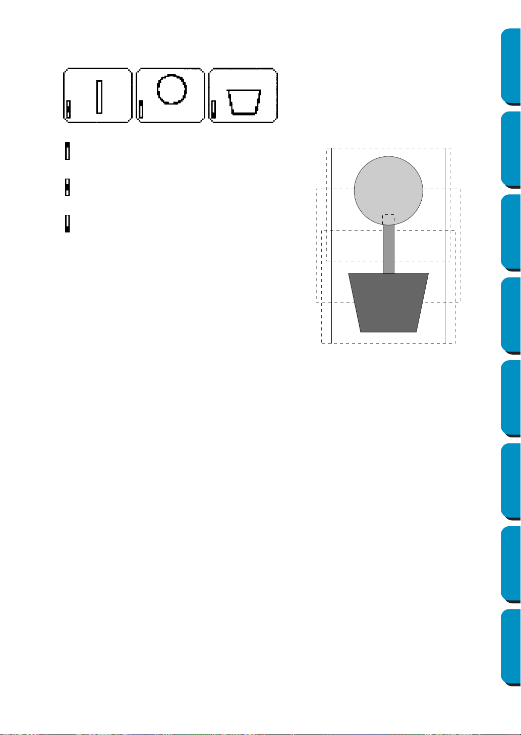
59
Contents Before Using Getting Started Design Center Layout & Editing
Programmable
Stitch Creator
Quick Reference Alphabetic Index
If the pattern shown below at the right is written to an original card and the written pattern is
checked on the embroidering machine, it will appears as follows.
Therefore, the frame installation position sewing order for the pattern shown above is b, a, then c.
: This pattern is sewn when the embroidery
frame is installed at the top installation posi-
tion (position a).
: This pattern is sewn when the embroidery
frame is installed at the middle installation
position (position b).
: This pattern is sewn when the embroidery
frame is installed at the bottom installation
position (position c).

60
Contents Before Using Getting Started Design Center Layout & Editing
Programmable
Stitch Creator
Quick Reference Alphabetic Index
Notes on embroidering using the multi-position embroidery frame:
• Before embroidering your project, sew a trial sample of the pattern on a scrap piece of fabric
that is the same as that used for your project. In addition, use the correct needle and thread.
• Be sure to affix stabilizer material to the back of the fabric and tightly stretch the fabric within
the embroidery frame. When embroidering on thin or stretch fabrics, use two layers of stabilizer
material. If no stabilizer material is used, the fabric may become over-stretched or wrinkled or
the embroidery may not be sewn correctly.
• Use the zigzag stitch for sewing the outlines in order to prevent embroidering outside the out-
lines.
• For patterns that require the embroidery frame
to be installed at different installation posi-
tions, design the embroidery pattern data so
that the various parts of the pattern overlap in
order to prevent misalignment while embroi-
dering.
61
Contents Before Using Getting Started Design Center Layout & Editing
Programmable
Stitch Creator
Quick Reference Alphabetic Index
Design Center is used to create individual patterns from image files created with other applications. You
can also apply stitch patterns created with Programmable Stitch Creator to regions of images displayed
in Design Center. The resulting embroidery pattern can then be imported into the Layout & Editing
Design Page and combined with other patterns.
The embroidery pattern is created in four stages:
◆ STAGE 1: Original image
You can open an image that you purchased from a commercial source, created using an application such
as Paintbrush or scanned from a printed source using a scanner and the appropriate software.
The image file must be in the uncompressed format, its file name extension must be bmp, tif, jpg, j2k, pcx,
wmf, png, eps, pcd, or fpx
.
Note that graphic files in other formats can be converted into the specified format if you have the proper
conversion software.
In Stage 1, the image is displayed with its original colors and you cannot modify it.
◆ STAGE 2: Line image
To move from Stage 1 to Stage 2, you select maximum 5 colors of the image data that will be converted
into black outlines. Unselected colors will be converted into white. You can then correct the black and
white image using pens and erasers of different thicknesses.
If you save the file in Stage 2, its file name extension will be PEL.
◆ STAGE 3: Figure handle image
When you move to Stage 3, the application automatically detects the outline of the black areas and
replaces it with a set of broken lines. The broken lines can be edited (you can move and delete points or
insert new points).
If you save the file in Stage 3, its file name extension will be PEM.
◆ STAGE 4: Sewing settings
You can set the stitch, thread color, etc. for the outlines and regions to complete the embroidery data
If you save the file in Stage 4, its file name extension will be PEM.
If you have to interrupt your work at stage 2, 3 and 4, save the file and retrieve it later to resume working.
Design Center
STAGE 1: Original image
STAGE 2: Line image
STAGE 3: Sewing settings
STAGE 4: Figure handle image
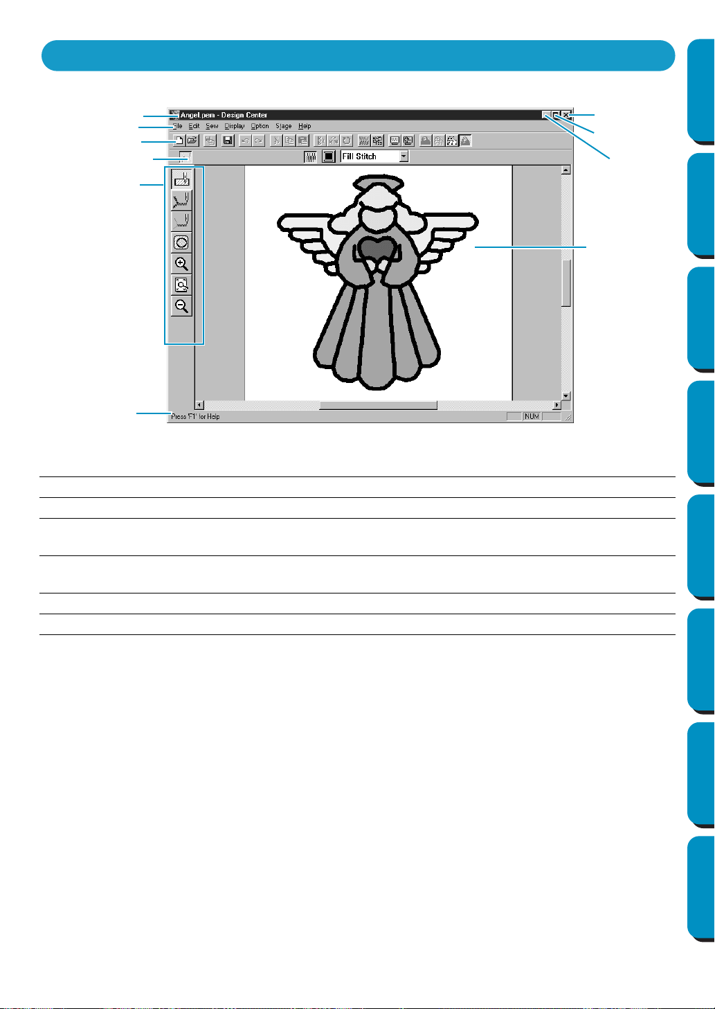
62
Contents Before Using Getting Started Design Center Layout & Editing
Programmable
Stitch Creator
Quick Reference Alphabetic Index
Menu bar Gives access to the functions.
Toolbar Shortcut for the menu functions.
Sewing attributes bar Sets the sewing attributes (color, stitch) of the patterns (displays in Stage
4 only)
Tool box Used to select and edit the image. Stage 1 has no Tool Box; the other
stages all have a different Tool Boxes.
Status bar Provides short information.
Design Page The actual part of the work area that can be saved and sewn.
The Screen
Menu bar
Toolbar
Sewing attributes bar
Tool box
Design Page
Status bar
(different in each stage)
Title bar
Close button
Maximize
Minimize
button
button
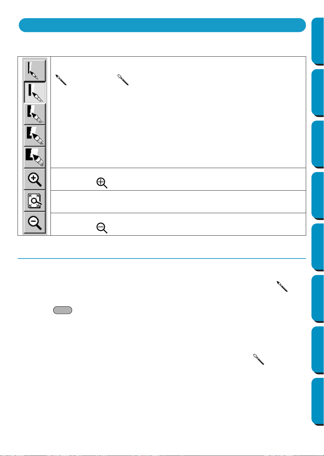
63
Contents Before Using Getting Started Design Center Layout & Editing
Programmable
Stitch Creator
Quick Reference Alphabetic Index
In Stage 2, the Tool Box is used to modify the line image generated from the original image or to create a
line image from scratch.
Drawing and Erasing
■ Drawing
1 Click the button with the desired pen thickness on the Tool Box. The cursor changes to .
2 To add a dot, click; to draw a line, drag with the mouse’s left button.
If the key is held down while moving the mouse, only vertical or horizontal lines will be
drawn.
■ Erasing
1
Click the button with the desired eraser thickness on the Tool Box.
2 To erase, drag while pressing the mouse’s right button. The cursor changes to .
The five first buttons are used as pens and erasers of different thicknesses.
Cursor shape when moved or dragged over the work area:
for the pens and for the erasers.
When you start the application, the number 2 Pen tool is active by default.
Sets the cursor in zoom-in mode.
Cursor shape:
Maximizes the selected Design Page to fit in the window.
Sets the cursor in zoom-out mode.
Cursor shape:
Using the Stage 2 Tool Box
Shift
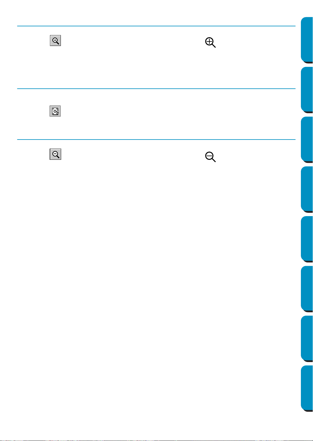
64
Contents Before Using Getting Started Design Center Layout & Editing
Programmable
Stitch Creator
Quick Reference Alphabetic Index
Zoom-in Mode
1 Click on the Tool Box. The shape of the cursor changes to .
2 Click on the area you want to enlarge or drag the cursor across the area that you want to enlarge,
then release it. You can repeat this step several times.
Fit Design Page to Window
This feature allows you to maximize the selected Design Page so that it will fit in the window.
1 Click on the Tool Box. The Design Page is enlarged or shrunk automatically to fit the window.
Zoom-out Mode
1 Click on the Tool Box. The shape of the cursor changes to .
2 Click on the area you want to shrink or drag the cursor across the area that you want to shrink,
then release it. The image shrinks toward that point. You can repeat this step several times.
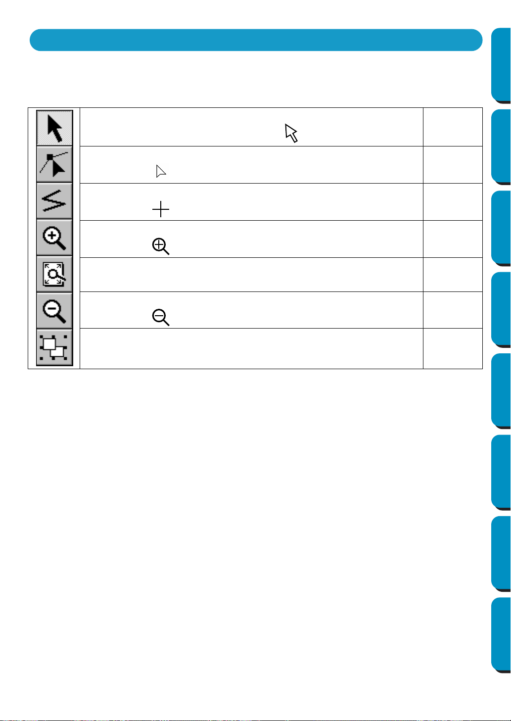
65
Contents Before Using Getting Started Design Center Layout & Editing
Programmable
Stitch Creator
Quick Reference Alphabetic Index
In Stage 3, outline data that has been generated automatically can be edited using the Tool Box.
Clicking a button of the Tool Box changes the cursor mode and shape. The left side of the Status bar tells
you what you can do in each cursor mode.
Sets the cursor in selection mode.When you start the application, the selec-
tion mode is active by default. Cursor shape:
page 66
Sets the cursor in point edit mode.
Cursor shape:
page 68
Sets the cursor in line drawing mode.
Cursor shape:
page 69
Sets the cursor in zoom-in mode.
Cursor shape:
page 69
Maximizes the selected Design Page to fit in the window.
page 70
Sets the cursor in zoom-out mode.
Cursor shape:
page 70
Fills the display with the selected objects.
page 70
Using the Stage 3 Tool Box
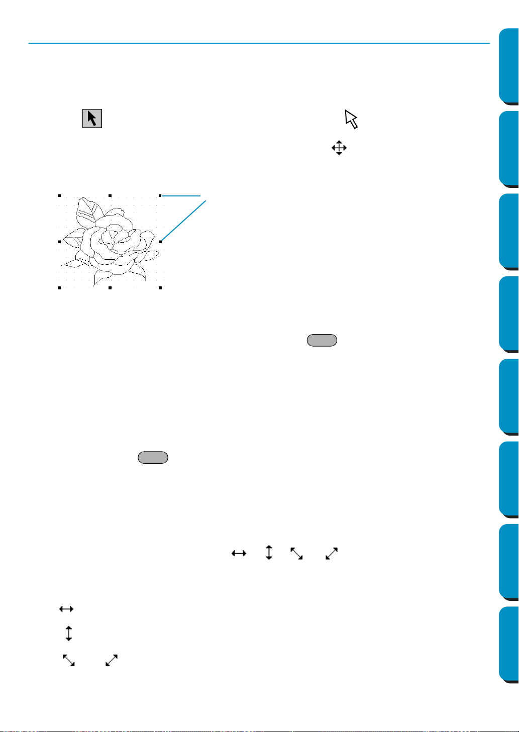
66
Contents Before Using Getting Started Design Center Layout & Editing
Programmable
Stitch Creator
Quick Reference Alphabetic Index
Selection Mode
The cursor selection mode is used to select one or more outlines. Once an outline is selected, you can
move it, scale it, and change its direction by rotating it or inverting it.
■ Selecting patterns
1
Click on the Tool Box. The shape of the cursor changes to .
2 Click the pattern that you want to select. The cursor changes when it touches an outline.
You know that the object is selected when handles are displayed and the outlines display in blue.
Note that a pattern will not be selected if you click on a transparent part of it.
3 To deselect the pattern, select another one, click on the white space or click another button of the
Tool Box, except a Zoom tool.
4 To select an additional pattern, click it while holding the key down.
Note that you can also select patterns by dragging the cursor across the whole pattern that you
want to select. As you drag, a dotted rectangle appears. When you release the mouse button, all
patterns that are completely contained in that rectangle will be selected.
■ Moving patterns
1
Select the data that you wish to move.
2 Position the cursor over the data and click (a dotted box appears around the data), then drag to a
new destination.
Holding down the key while dragging the pattern moves the pattern horizontally or vertically.
NOTE:
By pressing the arrow keys, the selected pattern can be moved 0.5 mm (about 0.02 inch) to the
left, right, up or down.
■ Scaling patterns
1
Move the cursor over one of the handles of a selected pattern or group of selected patterns.
The shape of the cursor will change to , , or , depending on the handle the
cursor is on.
2 Drag the handle in the direction of the arrow to scale the pattern.
is for scaling the width.
is for scaling the height.
and are for scaling both dimensions at the same time.
Handles
Shift
Shift
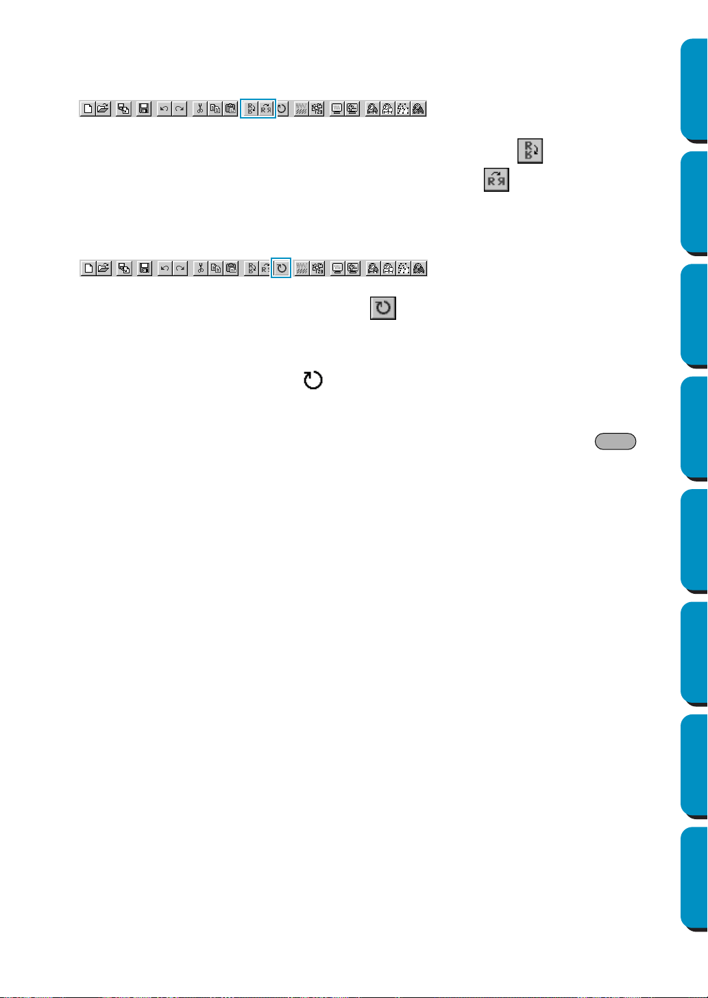
67
Contents Before Using Getting Started Design Center Layout & Editing
Programmable
Stitch Creator
Quick Reference Alphabetic Index
■ Flipping a pattern horizontally or vertically
1
Select the data that you wish to flip horizontally (up/down) or vertically(left/right). The buttons
below become active.
2 To flip horizontally, select the command Edit – Mirror – Horizontal or click on the Toolbar.
To flip vertically, select the command
Edit – Mirror – Vertical or click on the Toolbar.
■ Rotating a pattern
1
Select the data that you wish to rotate.The button below becomes active.
2 Select the menu command Edit – Rotate or click on the Toolbar. The handles around the
selected pattern are replaced by smaller boxes on the four corners of the selected area.
3 To rotate the pattern, move the cursor on one of the four rotation handles.
The shape of the cursor changes to as soon as your cursor touches a rotation handle. Click
on a rotation handle and a lined box appears around the selected the pattern.
You can rotate the pattern clockwise or counterclockwise by dragging the mouse.
A simple dragging of the mouse will rotate the pattern by 1˚ increments. Pressing the key
will rotate it by 15˚ increments.
Shift
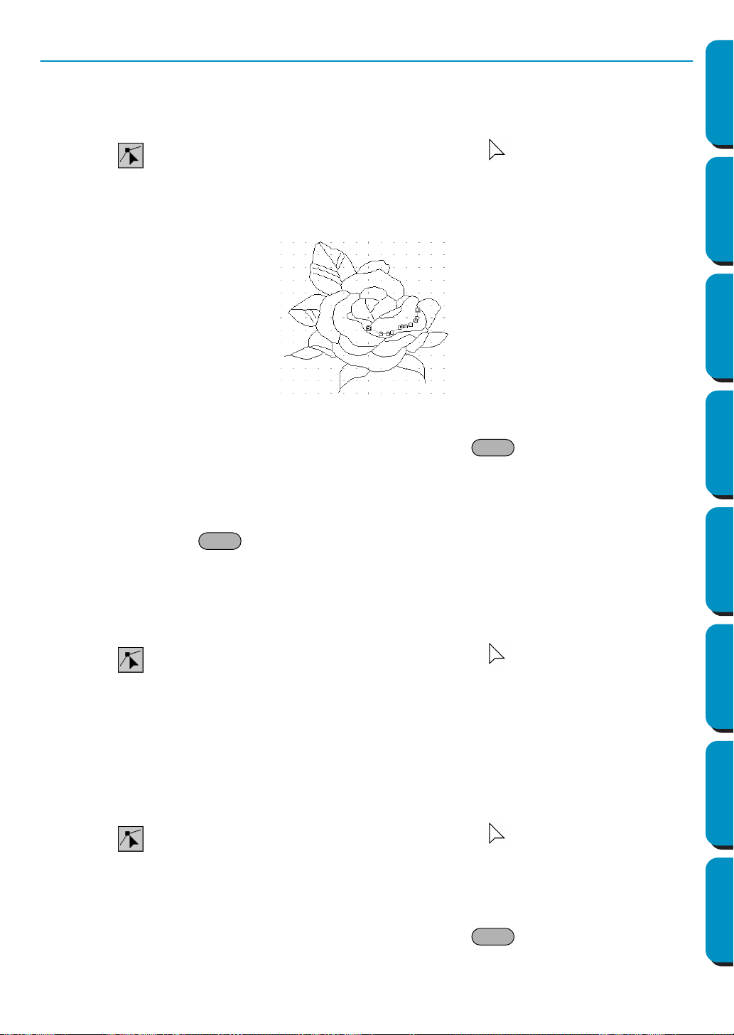
68
Contents Before Using Getting Started Design Center Layout & Editing
Programmable
Stitch Creator
Quick Reference Alphabetic Index
Point Edit Mode
The point edit mode allows you to move, insert and delete points in an outline.
■ Moving points
1
Click on the Tool Box. The shape of the cursor changes to .
2 Click the outline that you want to edit.
The selected line displays in pink and existing points of the selected line are marked with small
empty squares. The starting and ending points of a line are marked by bigger squares.
3 Click the point that you want to move.
To select an additional point, click that point while holding the key down.
The selected points are marked by filled squares.
NOTE:
If you click on the line instead of a square, a new point is inserted.
4 Drag the cursor to a new position. All the selected points move in the same direction.
Holding down the key while dragging the point moves the point horizontally or vertically.
NOTE:
By pressing the arrow keys, the selected point can be moved 0.1mm (about 0.01 inch) to the left,
right, up or down.
■ Inserting points
1
Click on the Tool Box. The shape of the cursor changes to .
2 Click the outline that you want to edit.
The selected line displays in pink and existing points of the selected line are marked with small
empty squares. The starting and ending points of a line are marked by bigger squares.
3 Click where you want to insert a new point on the outline.
A new point appears, marked by a filled black square. The new point can be edited.
■ Deleting points
1
Click on the Tool Box. The shape of the cursor changes to .
2 Click the outline that you want to edit.
The existing points of the outline are marked with small empty squares.
3 Click the point that you want to delete.
To select an additional point, click that point while holding the key down.
The selected points are marked by filled squares.
Shift
Shift
Shift
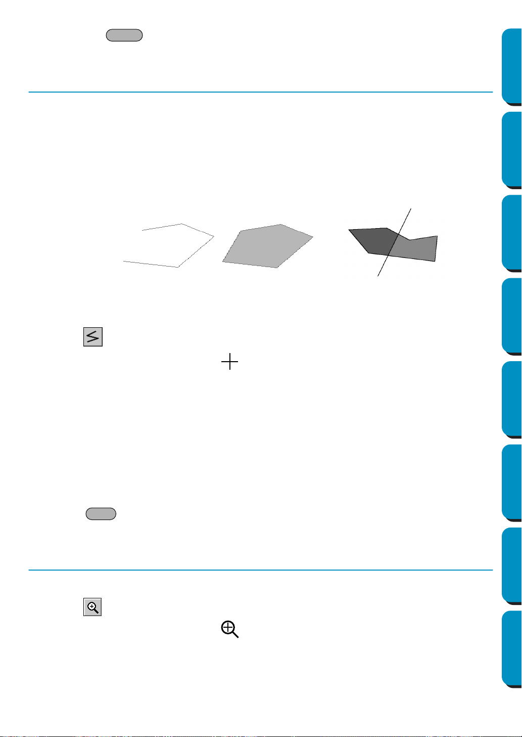
69
Contents Before Using Getting Started Design Center Layout & Editing
Programmable
Stitch Creator
Quick Reference Alphabetic Index
4 Press the key to remove the point from the outline.
Note that the points marked by red squares cannot be deleted.
Line Drawing Mode
The line drawing mode allows you to add broken lines to your pattern. A broken line is made of one or
more contiguous straight lines, the ending point of a straight line being the starting point of the next one.
If the broken line you drew did not create enclosed regions, it remains a simple outline and you can only
set sewing attributes for the line itself in Stage 4.
If the broken line did create enclosed regions, you can assign stitches and colors to both the outline and
the regions in Stage 4.
If you draw a line through an existing region, creating two separate regions, you will be able to set sewing
attributes to both separately, as well as to the separating line.
■ Drawing a broken line
1
Click on the Tool Box.
The shape of the cursor changes to and is displayed together with a small image of the tool
button.
2 Draw the line.
Move the mouse to the starting point and click.
Move the mouse to the ending point of the first straight line and click again.
NOTE:
You can always remove the last-entered point by clicking the mouse’s right button.
If needed, use the grid to help you draw the lines. You can set the grid so that each of its vertical
and horizontal lines are visible. For more information on the grid, refer to “Grid Setup” on page
103.
3 Repeat until you arrive at the last end point. At that point double-click.
If the key is held down while moving the mouse, only vertical or horizontal lines will be
drawn.
Zoom-in Mode
The zoom-in mode is used to magnify a part of the outline so that you can check it and edit it more easily.
1 Click on the Tool Box.
The shape of the cursor changes to .
2 Click on the area you want to enlarge or drag the cursor across the area that you want to enlarge,
then release it. You can repeat this step several times.
Delete
Broken line without a region
Broken line with region
Starting point
Ending point
Broken lines with two regions
Shift
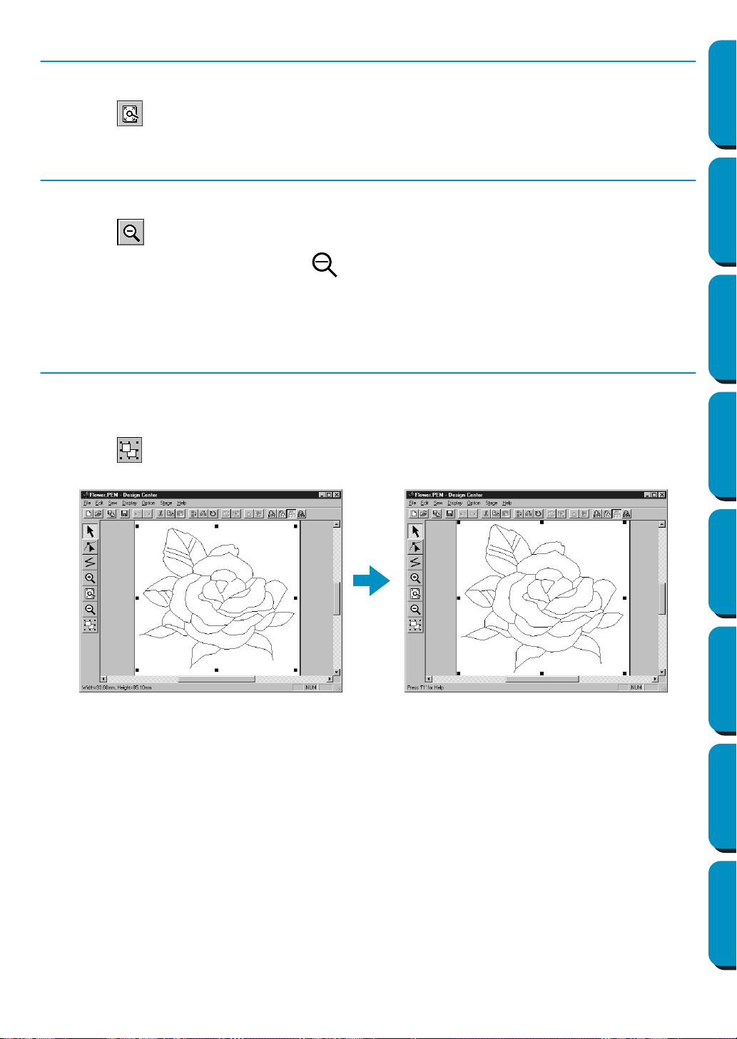
70
Contents Before Using Getting Started Design Center Layout & Editing
Programmable
Stitch Creator
Quick Reference Alphabetic Index
Fit Design Page to Window
This feature allows you to maximize the selected Design Page so that it will fit in the window.
1 Click on the Tool Box. The Design Page is enlarged or shrunk automatically to fit the window.
Zoom-out Mode
The zoom-out mode is used to return to the normal display after zooming in.
1 Click on the Tool Box.
The shape of the cursor changes to .
2 Click on the area you want to shrink or drag the cursor across the area that you want to shrink,
then release it. The image shrinks toward that point. You can repeat this step several times.
Enlarging Selected Outlines to the Screen Size
The last button of the Tool Box allows you to quickly enlarge a selected outline to the screen size.
1 Select one or more outlines.
2 Click on the Tool Box.
The selected outlines now occupy all the available space on the screen.

71
Contents Before Using Getting Started Design Center Layout & Editing
Programmable
Stitch Creator
Quick Reference Alphabetic Index
In Stage 4, outline data from Stage 3 are assigned line and region sewing attributes. This is done by
using the Tool Box and the Sewing Attributes bar.
Clicking a button of the Tool Box changes the cursor mode and shape. The left side of the Status bar tells
you what you can do in each cursor mode.
Region Setting Mode
In this mode, you can apply the current sewing attributes to an enclosed region. You can also change the
sewing attributes applied to a region.
■ Applying the sewing attributes to a region
1
Click on the Tool Box.
The shape of the cursor changes to and is displayed together with a small rectangle.
The Sewing Attributes bar now looks like this:
You can select the color and stitch at this step or after applying them to the region. See “Color” on
page 79 and “Stitch” on page 80.
You can also use the menu (see “Sewing Attributes” on page 96) or the following method to define
the density and other characteristics of the stitch. If you do not make these settings at this stage,
the current settings will be applied, but you can modify them later.
Sets the cursor in region setting mode.
When you start the application, this tool is active by default
Cursor shape: , with a miniature of the button
page 71
Sets the cursor in line (all) setting mode.
Cursor shape: , with a small image of the button
page 73
Sets the cursor in line (part) setting mode.
Cursor shape: , with a small image of the button
page 74
Sets the cursor in hole sewing mode.
Cursor shape: , with a small image of the button
page 76
Sets the cursor in zoom-in mode.
Cursor shape:
page 76
Maximizes the selected Design Page to fit in the window.
page 76
Sets the cursor in zoom-out mode.
Cursor shape:
page 76
Using the Stage 4 Tool Box
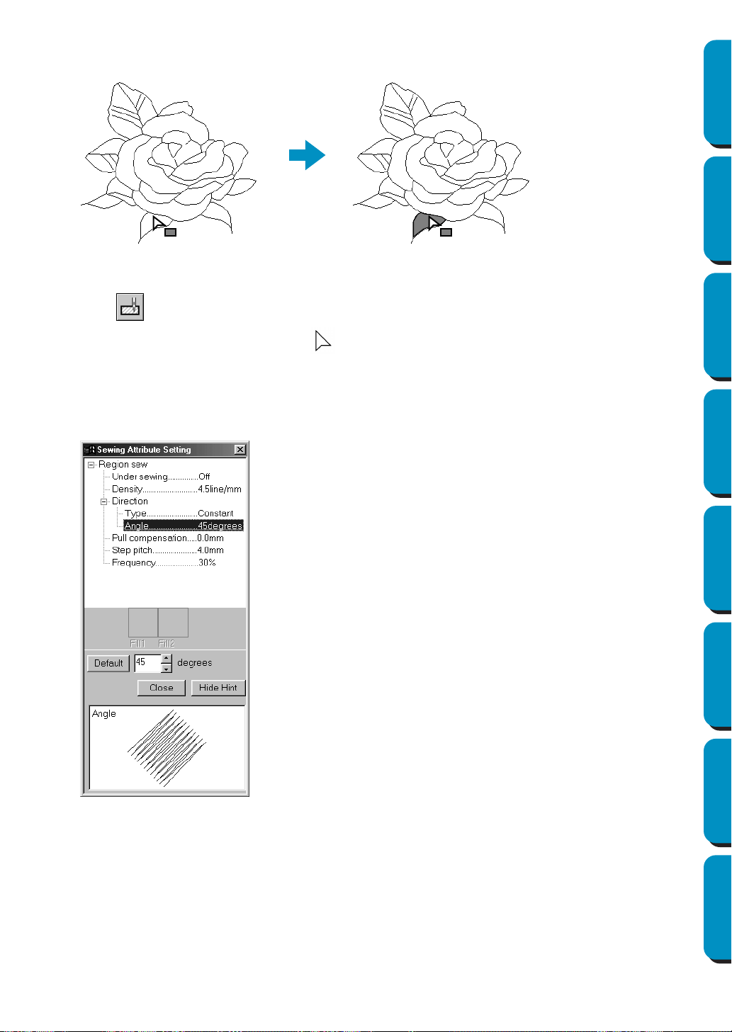
72
Contents Before Using Getting Started Design Center Layout & Editing
Programmable
Stitch Creator
Quick Reference Alphabetic Index
2 Click the enclosed region that you want to set.
The color and stitch selected on the Sewing Attributes bar are applied to the region.
■ Checking the sewing attributes of a region
1
Click on the Tool Box.
The shape of the cursor changes to and is displayed together with a small rectangle.
2 Click the enclosed region using the mouse’s right button.
The Sewing Attributes bar shows the color and stitch for the selection. You can change the color
and stitch at this step (see “Applying the sewing attributes to a region” on page 71).
The Sewing Attribute Setting dialog for the selected stitch displays.
◆ If necessary, change the settings.
See “Sewing Attributes” on page 96.
• To restore the default value of a set-
ting after changing it, click the
Default
button at the left of that setting.
◆ To apply the new settings to the
region, click each region you want to
apply those settings to using the left
button.
◆ Click
Close to remove the dialog from
the screen.
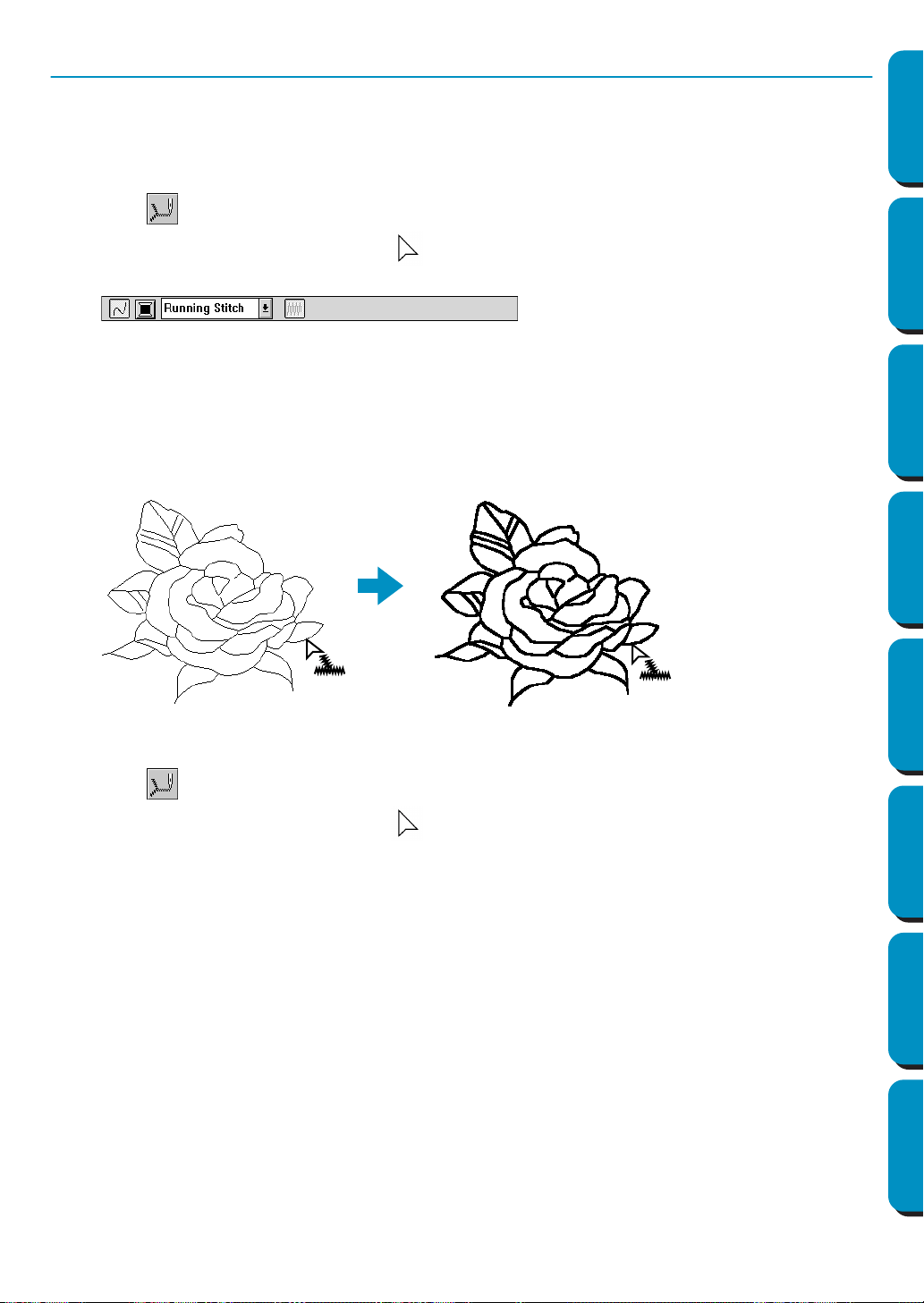
73
Contents Before Using Getting Started Design Center Layout & Editing
Programmable
Stitch Creator
Quick Reference Alphabetic Index
Line (all) Setting Mode
In this mode, you can apply the current sewing attributes to the outline of patterns. You can also change
the sewing attributes applied to outlines.
■ Applying the sewing attributes to an outline
1
Click on the Tool Box.
The shape of the cursor changes to and is displayed together with a small figure of the Tool
Box button. The Sewing Attributes bar now looks like this:
You can select the color and stitch at this step or after applying them to the outline. See “Color” on
page 79 and “Stitch” on page 80.
You can also use the menu (See “Sewing Attributes” on page 96) or the following method to define
the characteristics of the stitch. If you do not make these settings now, the current settings will be
applied, but you can modify them later.
2 Click the outline that you want to set.
The color and stitch selected on the Sewing Attributes bar are applied to the clicked outline.
■ Checking the sewing attributes of an outline
1
Click on the Tool Box.
The shape of the cursor changes to and is displayed together with a small figure of the Tool
Box button.
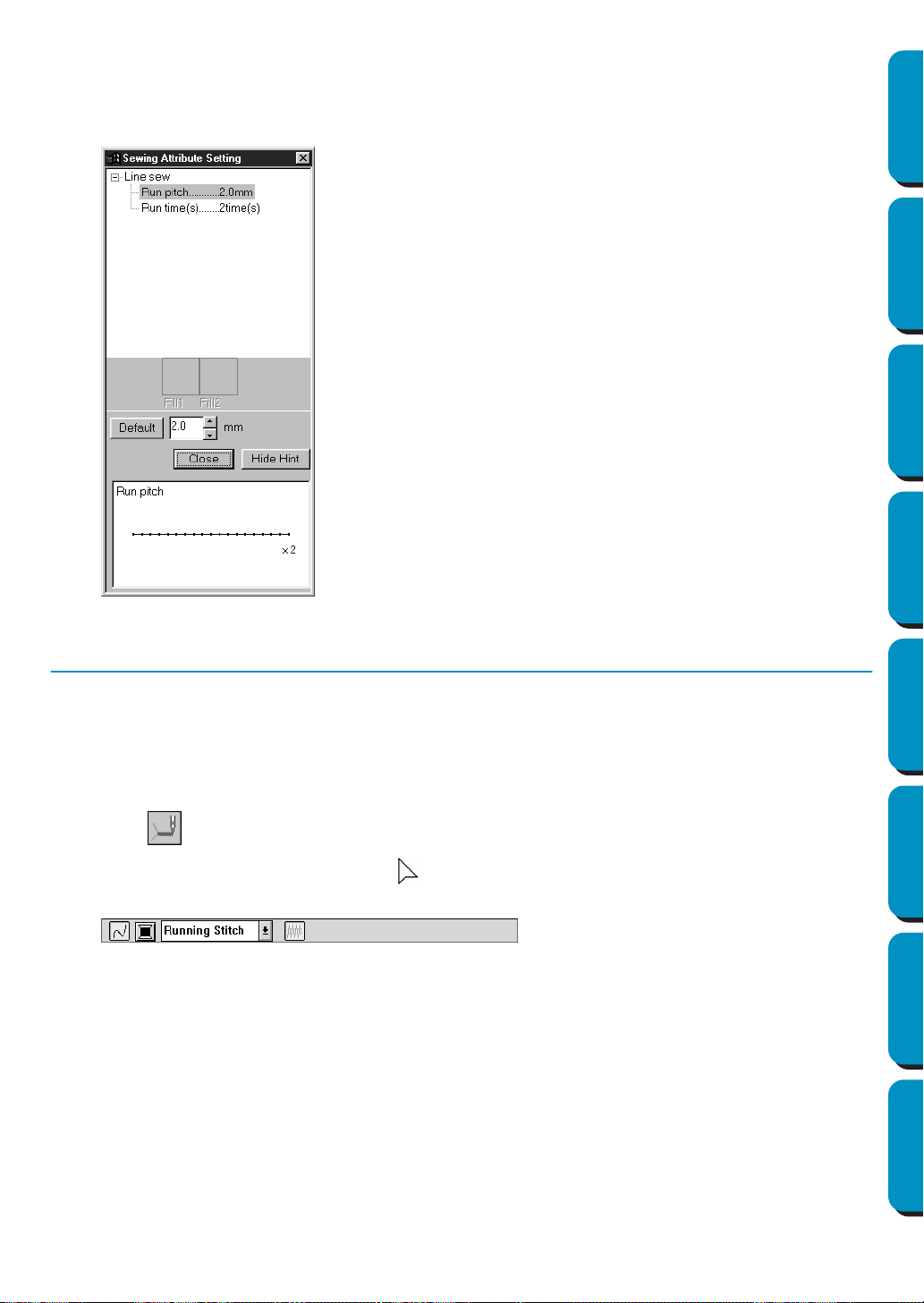
74
Contents Before Using Getting Started Design Center Layout & Editing
Programmable
Stitch Creator
Quick Reference Alphabetic Index
2 Click the outline using the mouse’s right button.
The Sewing Attributes bar shows the color and stitch for the selection. You can change the color
and stitch at this step (see “Applying the sewing attributes to an outline” on page 73).
The
Sewing Attribute Setting dialog for the selected stitch displays.
Line (part) Setting Mode
In this mode, you can apply the current sewing attributes to a portion of the outline. You can also change
the sewing attributes applied to a portion of the outline.
A single line of the outline extends from both sides of the cursor position to the next branch points.
■ Applying the sewing attributes to a portion of the outline
1
Click on the Tool Box.
The shape of the cursor changes to and is displayed together with a small figure of the Tool
Box button. The Sewing Attributes bar now looks like this:
You can select the stitch at this step or after applying them to a portion of the outline. See “Stitch”
on page 80. The color cannot be set separately for a portion of the outline. If you set a portion of
the outline before setting the whole outline, the default color will be black.
2 You can also use the menu (see “Sewing Attributes” on page 96) or the method described on page
75 (Checking the sewing attributes of a portion of an outline) to define the characteristics of the
stitch. If you do not make these settings now, the current settings will be applied, but you can mod-
ify them later.
◆ If necessary, change the settings.
See “Sewing Attributes” on page 96.
• To restore the default value of a set-
ting after changing it, click the
Default
button at the left of that setting.
◆ To apply the new settings to the out-
line, then click the outline of the pat-
tern(s) using the left button.
◆ Click Close to remove the dialog from
the screen.

75
Contents Before Using Getting Started Design Center Layout & Editing
Programmable
Stitch Creator
Quick Reference Alphabetic Index
3 Click the line of the outline that you want to set.
The stitch selected on the Sewing Attributes bar are applied to the line.
■ Checking the sewing attributes of a portion of an outline
1
Click on the Tool Box.
The shape of the cursor changes to and is displayed together with a small figure of the Tool
Box button.
2 Click the line you want to check using the mouse’s right button.
The Sewing Attributes bar shows the color and stitch for the selection. You can change the stitch
(not the color) at this step (see “Applying the sewing attributes to a region” on page 71).
The
Sewing Attribute Setting dialog for the selected stitch displays.
◆ If necessary, change the settings.
See “Sewing Attributes” on page 96.
• To restore the default value of a set-
ting after changing it, click the
Default
button at the left of that setting.
◆ To apply the new settings to single
lines, click the lines you want to apply
the settings to with the left button.
◆ Click
Close to remove the dialog from
the screen.
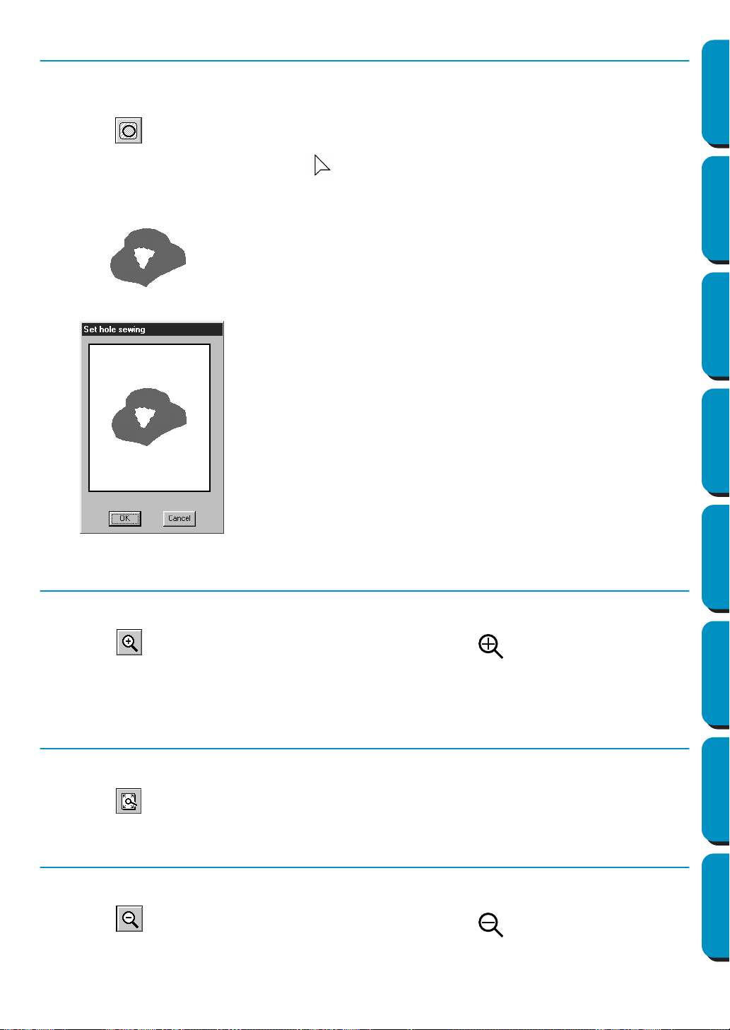
76
Contents Before Using Getting Started Design Center Layout & Editing
Programmable
Stitch Creator
Quick Reference Alphabetic Index
Hole Sewing Mode
The hole sewing mode is used to avoid sewing overlapping areas twice. It can be set only when one of
the overlapping areas is completely enclosed in another area.
1 Click on the Tool Box.
The shape of the cursor changes to and is displayed together with a small figure of the Tool
Box button.
2
Click on the enclosing part of a pattern comprised of a region completely enclosed into another one
.
3 This dialog will display.
Zoom-in Mode
The zoom-in mode is used to magnify a part of the outline so that you can inspect it and edit it more easily
.
1 Click on the Tool Box. The shape of the cursor changes to .
2 Click on the area you want to enlarge or drag the cursor across the area that you want to enlarge,
then release it. You can repeat this step several times.
Fit Design Page to Window
This feature allows you to maximize the selected Design Page so that it will fit in the window.
1 Click on the Tool Box. The Design Page is enlarged or shrunk automatically to fit the window.
Zoom-out Mode
The zoom-out mode is used to return to the normal display after zooming in.
1 Click on the Tool Box. The shape of the cursor changes to .
2 Click on the area you want to shrink or drag the cursor across the area that you want to shrink,
then release it. The image shrinks toward that point. You can repeat this step several times.
◆ Click on the central region to toggle hole sew-
ing on/off.
◆ Click
OK to set hole sewing.
◆ Click
Cancel to exit without setting hole sewing.
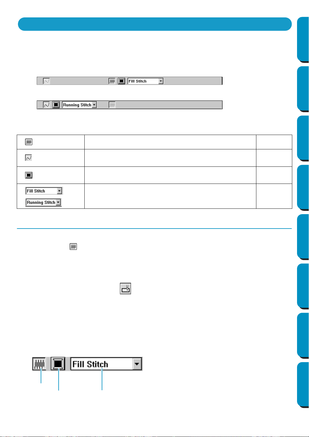
77
Contents Before Using Getting Started Design Center Layout & Editing
Programmable
Stitch Creator
Quick Reference Alphabetic Index
The Sewing Attributes, available in Stage 4, bar allows you to set the color and stitch of a region or out-
line.
The sewing attributes which are available depend on the cursor mode.
Example 1: The cursor is in the region setting mode.
Example 2: The cursor is in the line setting mode.
When the cursor is left for a while on an element of the Sewing Attributes bar, a label indicating the func-
tion of that element appears.
Setting the Thread Color and Stitch
■ Region sew
Purpose: Switches the inside region on/off.
When the inside region is switched off, it is not sewn (and you cannot set its color
or stitch).
Available: When you click on the Tool Box to put the cursor in the Region sewing
mode.
Operation:
1 Click the Region sew button.
This button has two states:
on: the Region color button and the Region sew type selector are displayed.
off: the Region color button and the Region sew type selector are not displayed.
Region sew: Switches the inside region on/off. page 77
Line sew: Switches line sew on/off. page 78
Region color, Line color: Sets the thread color for outline or region
inside.
page 79
Region sew type, Line sew type: Sets the stitch for outline or
region inside.
page 80
Using the Sewing Attributes Bar
Region sew
Region color
Region sew type
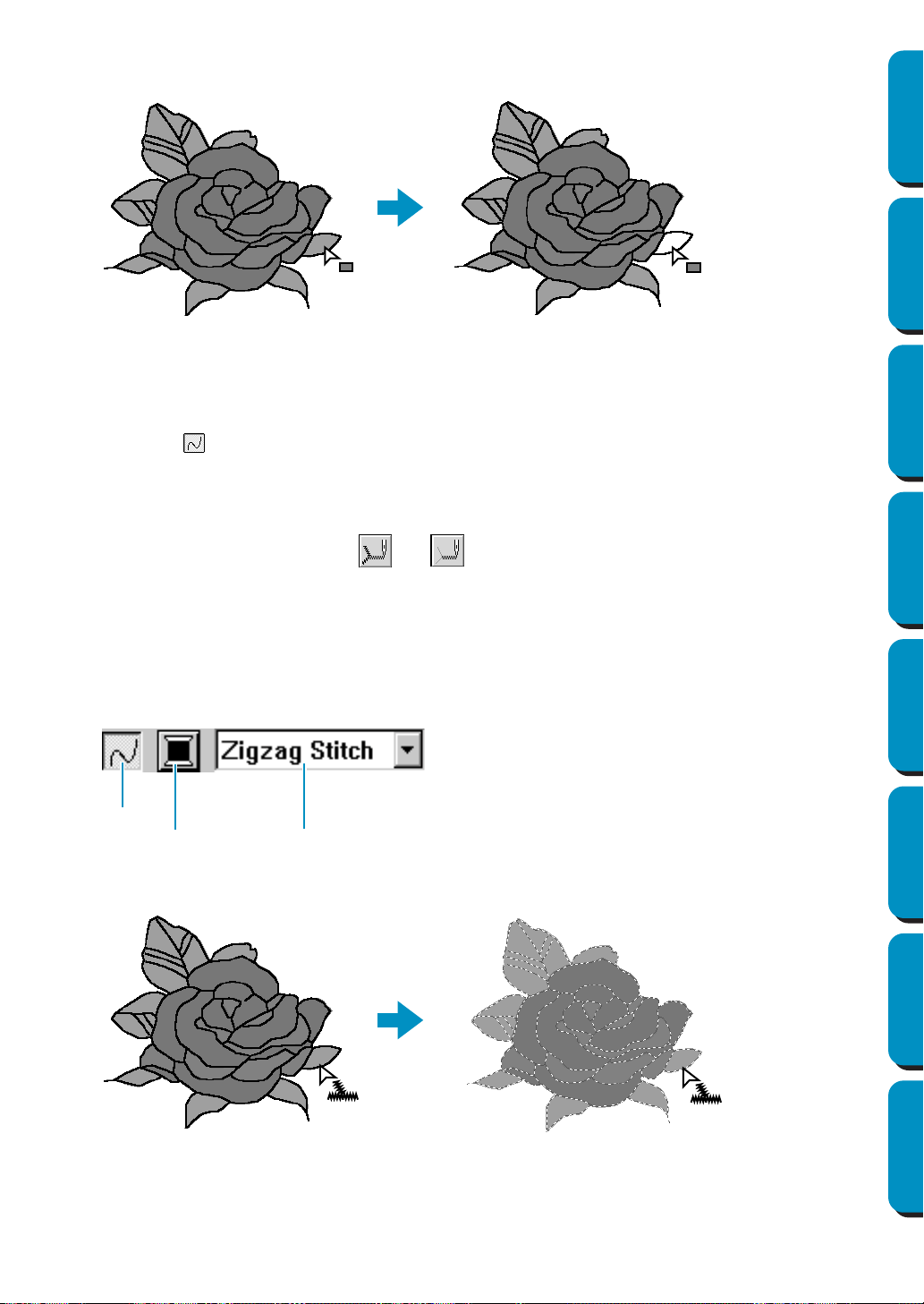
78
Contents Before Using Getting Started Design Center Layout & Editing
Programmable
Stitch Creator
Quick Reference Alphabetic Index
2 Click inside a region to turn it on or off.
When you turn off the region, the region disappears.
When you turn on the region, the region gets the color displayed on the
Region color button, and
the stitch displayed on the Region sew type selector.
See also: “Color” on page 79 and “Stitch” on page 80
■ Line sew
Purpose: Switches the outline on/off.
When the outline is switched off, it is not sewn (and you cannot set its color or stitch).
Available: When you click or on the Tool Box to put the cursor in the Line (all or
parts) sewing mode.
Operation:
1 Click the Line sew button.
This button has two states:
on: the Line color button and the Line sew type selector are displayed.
off: the Line color button and the Line sew type selector are not displayed.
2 Click an outline to turn it on or off.
When you turn off the outline, it is replaced by a dotted line that will not be sewn.
When you turn on the outline, the outline gets the color displayed on the Line color button, and the
stitch displayed on the Line sew type selector.
See also: “Color” on page 79 and “Stitch” on page 80
Line sew
Line color
Line sew type
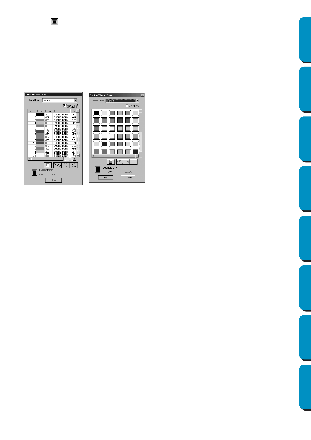
79
Contents Before Using Getting Started Design Center Layout & Editing
Programmable
Stitch Creator
Quick Reference Alphabetic Index
■ Color
Purpose: Sets the thread color for outline or region inside.
Available: When the cursor is in Region setting mode or Line setting mode.
Operation:
1 Click the Color button.
A Thread Color dialog similar to the one shown below appears.
Clear the View Details check box to view a list of only the thread colors.
When you click the desired color, the new color is displayed on the
Region color button or Line
color
button.
NOTE:
For details on specifying a user thread chart or for information on how machines handle thread
colors, refer to “Edit User Thread Chart” on page 225.
See also: “Region sew” on page 77, “Line sew” on page 78 and “Special colors” on page 145.
◆ From the Thread Chart list, select a system
chart or a user thread chart.
◆ From the list below, select the desired color.
The name of the selected color appears at the
bottom of the dialog.
• Descriptions for the four buttons under the list
are provided in “Special colors” on page 145.
◆ Click
Close to remove the dialog from the
screen.
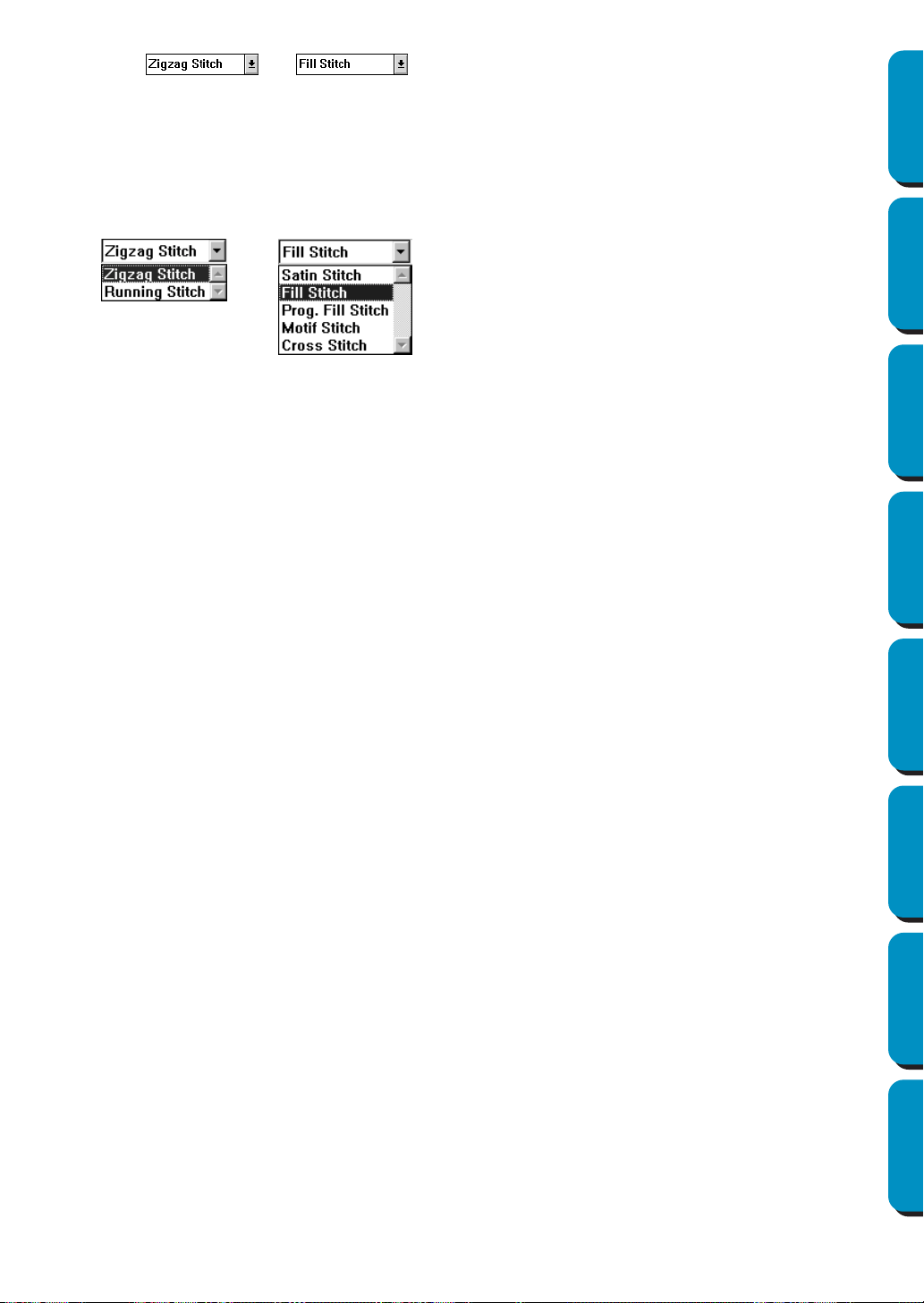
80
Contents Before Using Getting Started Design Center Layout & Editing
Programmable
Stitch Creator
Quick Reference Alphabetic Index
■ Stitch
Purpose: Sets the stitch for outline or region inside.
Available: When the cursor is in Region setting mode or Line setting mode.
Operation:
1 Click the sew type selector.
The available options display.
For outlines, Running Stitch and Zigzag Stitch are available. For regions Fill Stitch, Satin Stitch,
Programmable Fill Stitch, Motif Stitch and Cross Stitch are available.
2 Click the desired stitch.
The new setting displays on the selector.
“Region sew” on page 77 and “Line sew” on page 78
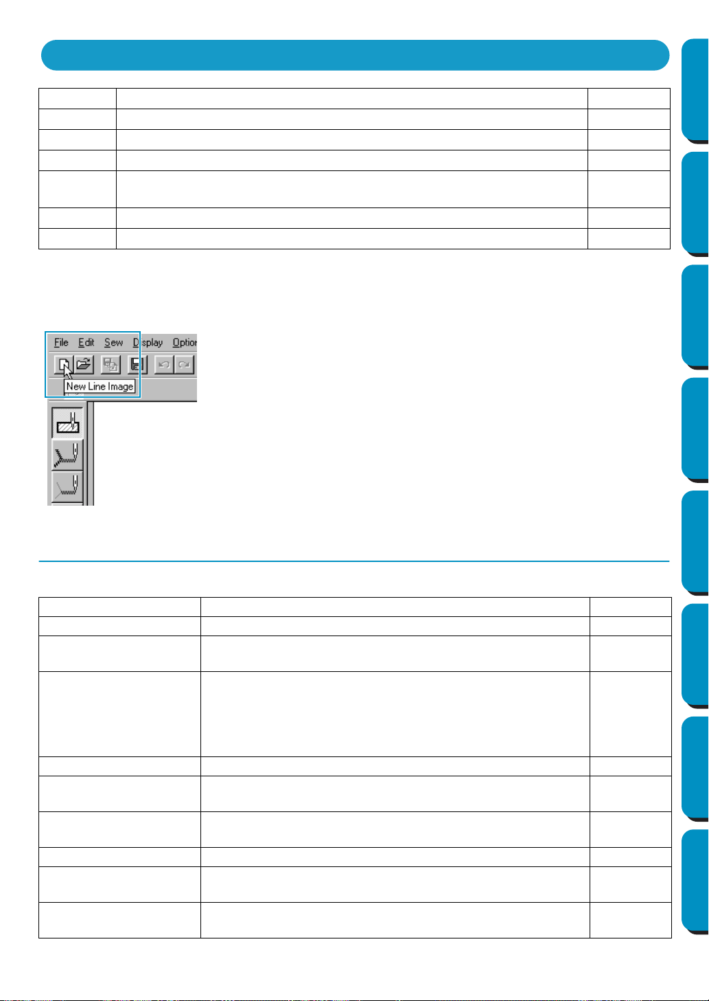
81
Contents Before Using Getting Started Design Center Layout & Editing
Programmable
Stitch Creator
Quick Reference Alphabetic Index
Many functions available on the menu can also be accessed by clicking an icon on the Toolbar or by
pressing a shortcut key or key combination.
When you leave the cursor for a while on a button of the Toolbar, a label indicating the function of the but-
ton displays.
File Menu
The File menu handles file input/output, such as opening, saving and printing.
File Handles file input/output, such as opening and saving. page 81
Edit Performs simple actions on selected objects, such as cutting and pasting. page 91
Sew Allows you to control the way the pattern will be sewn. page 96
Display Modifies the appearance of the screen. page 103
Option
Allows you to start the other applications and to set the Design Page size
and unit system.
page 106
Stage Allows you to move from one stage to the next or previous one. page 108
Help Gives you access to the on-screen help information system. page 113
New Line Image Creates a new blank Design Page and switches to Stage 2. page 82
New Figure Data Creates a new blank Design Page and switches to Stage 3. page 82
Wizard
Gives a step-by-step guide for creating pattern data, according
the type of data you want to create.
page 83
Open
Opens a previously saved file (*.PEM, *.PEL) or image file
(Windows BMP (*.bmp), Exif (*.tif, *.jpg), ZSoftPCX (*.pcx),
Windows Meta File (*.wmf), Portable Network Graphics
(*.png), Encapsulated PostScript (*.eps), Kodak PhotoCD
(*.pcd), FlashPix (*.fpx), JPEG2000 (*.j2k).
page 85
Select TWAIN device Selects which TWAIN device installed in the computer to use. page 86
Input from TWAIN
device
Operates a TWAIN standardized scanner or other device to
import an image.
page 86
Input from Clipboard
Opens a new design page in Stage 1, and puts the image data
on the clipboard.
page 87
Output to Clipboard Copies the Stage 1 image data to the clipboard. page 88
Import Figure
Adds a *.pem file to your Design Page (available only in Stage
3).
page 88
Save
Saves your Design Page on the disk as latest Version file
(default).
page 89
Using the Menu Bar and the Toolbar
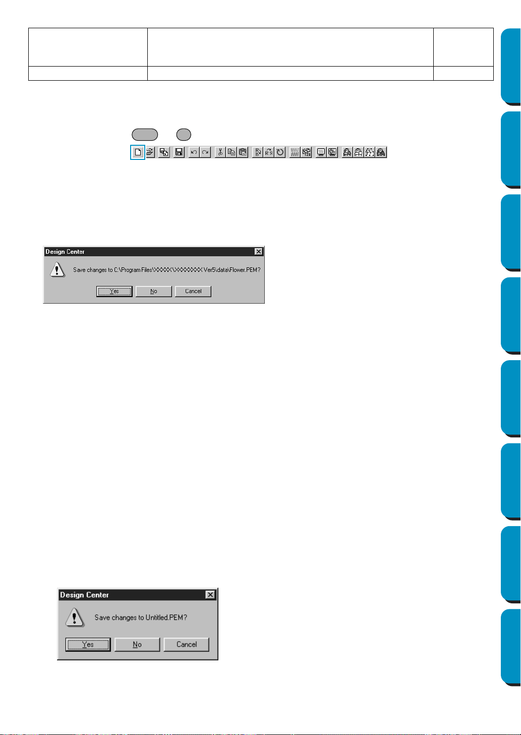
82
Contents Before Using Getting Started Design Center Layout & Editing
Programmable
Stitch Creator
Quick Reference Alphabetic Index
■ New Line Image
Purpose: Creates a new blank Design Page and switches to Stage 2.
Shortcut key: +
Toolbar:
Operation:
1 Click File, then New Line Image.
If the current Design Page is not edited, a new blank Design Page (Stage 2) appears immediately.
2 If the current Design Page is edited, you will be asked whether you want to save the changes, for
example:
Depending on the stage you are currently using and the editing you did, the file to be saved is a
*.pel file or a *.pem file or both.
A new file opens automatically in Stage 2. In Stage 2, you can use the pens and erasers to create
black and white drawings. You may also want to use this feature to create patterns that are easier
to draw by hand, for example, free-hand writing.
See also: “Open” on page 85, “Save” and “Save As” on page 89 and “New Figure Data”
below
■ New Figure Data
Purpose: Creates a new blank Design Page and switches to Stage 3.
Shortcut key: No shortcut key for this function
Toolbar: No button for this function
Operation:
1 Click File, then New Figure Data.
If the current Design Page is not edited, a new blank Design Page (Stage 3) appears immediately.
2 If the current Design Page is edited, you will be asked whether you want to save the changes, for
example:
Save As
Saves the current file under a new file name. Savable files are:
in Stage 1, Bitmap files (*.bmp); in Stage 2, PEL files; and in
Stage 3 and 4, PEL and PEM files.
page 89
Exit Exits the application. page 90
◆ Click Yes to save the Design Page first.
◆ Click
No to abandon the Design Page.
◆ Click
Cancel to do anything else (for exam-
ple, modifying the current Design Page or
saving it with another file name).
◆ Click Yes to save the Design Page first.
◆ Click No to abandon the Design Page.
◆ Click Cancel to do anything else (for exam-
ple, modify the current Design Page or sav-
ing it with another file name).
Ctrl N
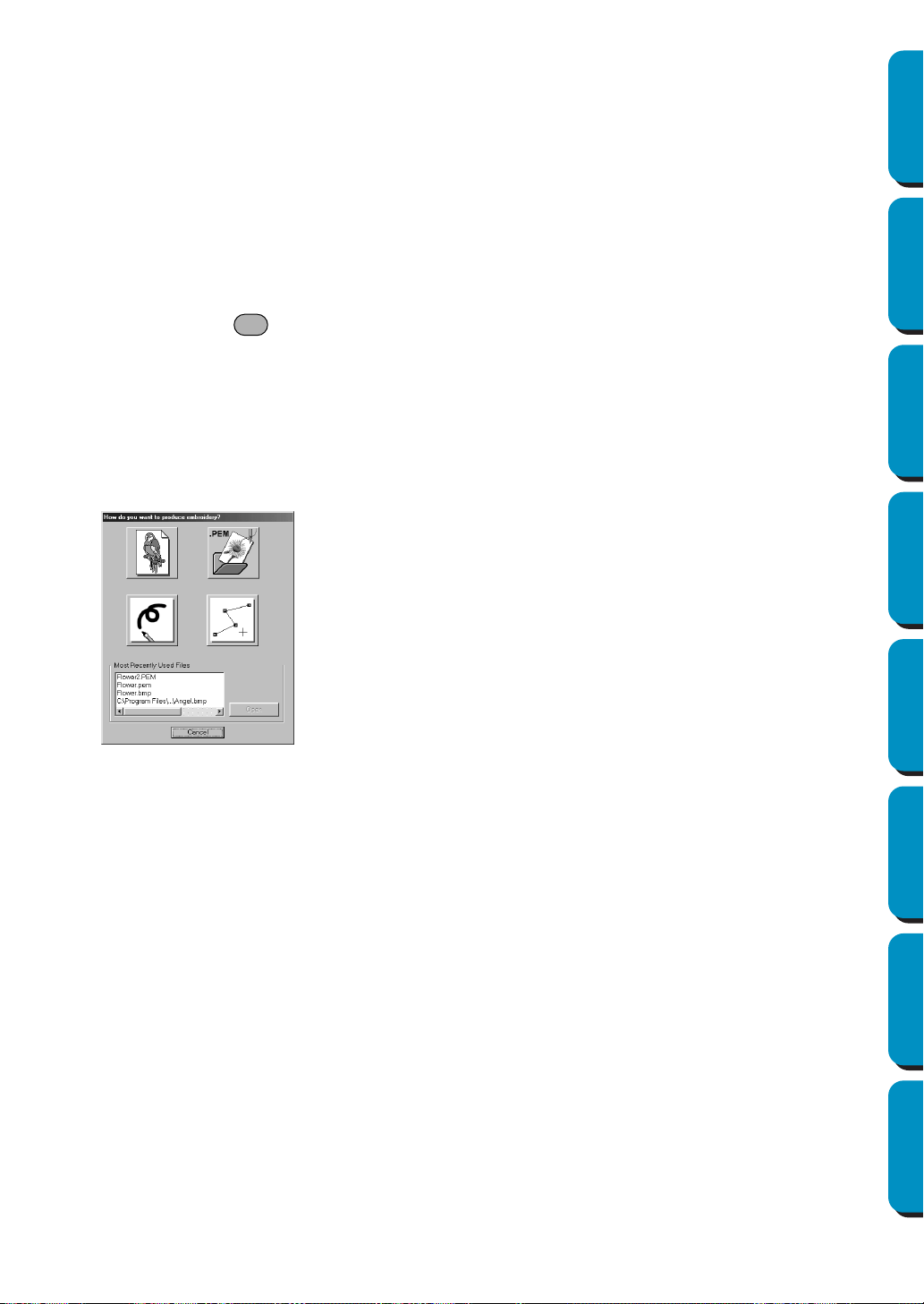
83
Contents Before Using Getting Started Design Center Layout & Editing
Programmable
Stitch Creator
Quick Reference Alphabetic Index
Depending on the stage you are currently using and the editing you did, the file to be saved is a
*.pel file or a *.pem file or both.
A new file opens automatically in Stage 3. The size of the Design Page is the currently set size.
In Stage 3, you can use the line drawing tool to draw lines, or you can use Import Figure to retrieve
the data from a saved pem file.
See also: “Open” on page 85, “Save” and “Save As” on page 89 and “New Line Image” on
page 82
■ Wizard
Purpose: Gives a step-by-step guide for creating pattern data, according the type of data
you want to create.
Shortcut key:
Toolbar: No button for this function
Operation:
1 Click File, then Wizard.
A step-by-step selection guide dialog similar to this will display.
(The same type of dialog will display when Design Center is running.)
However, if the current Design Page is edited, you will be asked whether you want to save the changes.
Position the mouse pointer over any button and the name of the action will display.
The functions for each button are described below.
◆ From Image
Use this button when creating normal embroidery data from an image.
Click the button, and the From Image dialog is displayed showing the next necessary step.
(See below)
◆ Open PEM
Use this button when you want to edit a saved (previously created) PEM file.
Click the button and the File Open dialog will open to select a PEM file.
For details, see the section in File – “Open” about PEM files (page 85).
◆ New Line Image
Opens a new Stage 2 Design Page.
Use this button when you want to use the black and white Pen tool to draw an image, then cre-
ate embroidery data from the image.
For details, see File – “New Line Image” (page 82).
◆ New Figure
Opens a new Stage 3 Design Page.
F3
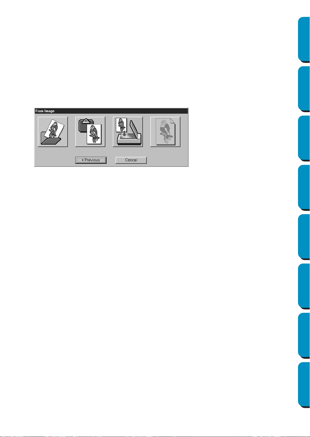
84
Contents Before Using Getting Started Design Center Layout & Editing
Programmable
Stitch Creator
Quick Reference Alphabetic Index
Use this button when you want to create data from vector data from the beginning, or when you
want to create data from vector data taken from a previously saved PEM file.
For details, see File – “New Figure Data” (page 82).
◆ Most Recently Used Files
Displays a list of the most recently edited files.
From the list, click the name of the file that you wish to edit, and then click OPEN.
◆ Cancel
Closes this dialog.
When From Image is selected
When you click the From Image button from the dialog on page 83, the following dialog opens.
Position the mouse pointer over any button and the name of the action will display.
The functions for each button are described below.
◆ Open Image File
Opens a previously saved image file and pastes it in the Design Page.
For details, see the section in File – “Open” about image files (page 85).
◆ From TWAIN device
Import an image from a TWAIN device and paste it in the Design Page.
For details, see File – “Input from TWAIN device” (page 86).
◆ From Clipboard
Pastes an image from the clipboard in the Design page. This function can only be used when
there is an image on the clipboard.
For details, see File – “Input from Clipboard” (page 87).
◆ Use Current image
Use an image opened in Stage 1. This function can only be used when an image is opened in
Stage 1.
◆ Previous
Closes the current dialog, and returns to the selection dialog from the previous step.
◆ Cancel
Closes this dialog.
If any button other than Previous/Cancel is clicked, the image importing operation will take place,
and the image will be pasted on the Stage 1 Design Page. After that, the Cut out to Line Image
dialog, which lets you choose colors for outlines, will open. You can then continue with creating
normal embroidery data.
For directions on that topic, see Stage – “To Line Image” (page 108).
After that, continue through the steps Stage – “To Figure Handle” (page 110) and Stage – “To Sew
Setting” (page 112) to create the data. For details, see those sections in the manual.
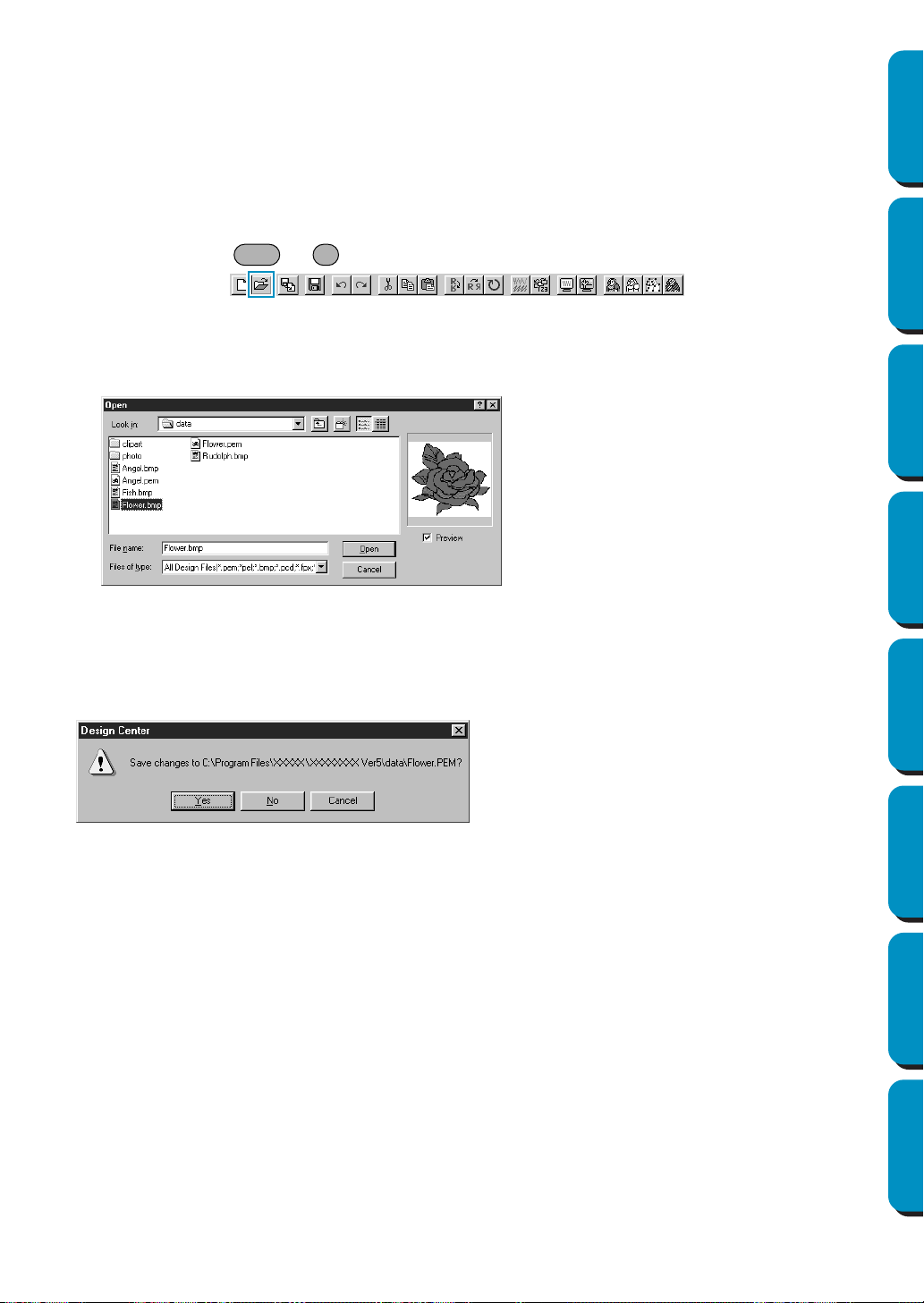
85
Contents Before Using Getting Started Design Center Layout & Editing
Programmable
Stitch Creator
Quick Reference Alphabetic Index
■ Open
Purpose: Opens a previously saved file (*.PEM, *.PEL) or image file (Windows BMP
(*.bmp), Exif (*.tif, *.jpg), ZSoftPCX (*.pcx), Windows Meta File (*.wmf), Portable
Network Graphics (*.png), Encapsulated PostScript (*.eps), Kodak PhotoCD
(*.pcd), FlashPix (*.fpx), JPEG2000 (*.j2k).
NOTE:
For pcd and fpx files that are saved on many pages, only the first page can be
opened. Tif files that have used LZW compression can not be opened.
Shortcut key: +
Toolbar:
Operation:
1 Click File, then Open.
A Open dialog similar to this will display.
2 The selected file opens immediately if your current Design Page is not edited.
If the current Design Page is edited, you will be asked whether you want to save the changes.
3 Depending on the stage you are currently using and the editing you did, the file to be saved is a
*.pel file or a *.pem file or both.
See also: “New Line Image” on page 82, “Save” and “Save As” on page 89
◆ Select the drive, the folder and the file
name.
• Be sure to select the right type of file
extensions in
List Files of Type.
• If the Preview check box is checked, the
content of the selected file displays in
the preview window.
◆ Click Open or double-click the file name
to open the file in Design Center.
◆ Click
Cancel to exit.
◆ Click
Yes to save the Design Page first.
◆ Click
No to abandon the Design Page.
◆ Click
Cancel to do anything else (for
example, modifying the current Design
Page or saving it with another file name).
Ctrl O
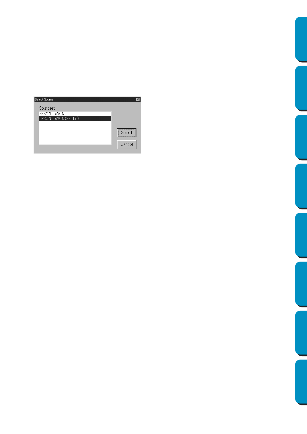
86
Contents Before Using Getting Started Design Center Layout & Editing
Programmable
Stitch Creator
Quick Reference Alphabetic Index
■ Select TWAIN device
Purpose: Selects which TWAIN device installed in the computer to use.
Shortcut key: No shortcut key for this function
Toolbar: No button for this function
Operation:
1 Click File, then Select TWAIN device.
A dialog similar to this will display.
From the devices in the display, select which device to use and highlight that device.
NOTE:
If there is no TWAIN device installed, there will be no names displayed on the Sources list.
Use this function after installing the driver software for the TWAIN device you want to use.
See also: “Input from TWAIN device” below
■ Input from TWAIN device
Purpose: Operates a TWAIN standardized scanner or other device to import an image.
Shortcut key: No shortcut key for this function
Toolbar: No button for this function
Operation:
1 Check that the scanner or other device is correctly connected.
2 Click File, then Input from TWAIN device.
The driver interface set in the
Select TWAIN device dialog is displayed.
Operate that interface, make the settings for importing an image, and import the image.
NOTE:
For information on using the interface, see the help manual for that interface, or contact the manu-
facturers of the interface.
◆ Click
Select to choose the selected
device and close the dialog.
◆ Click Cancel to ignore the operation
done to change the device and close
the dialog.
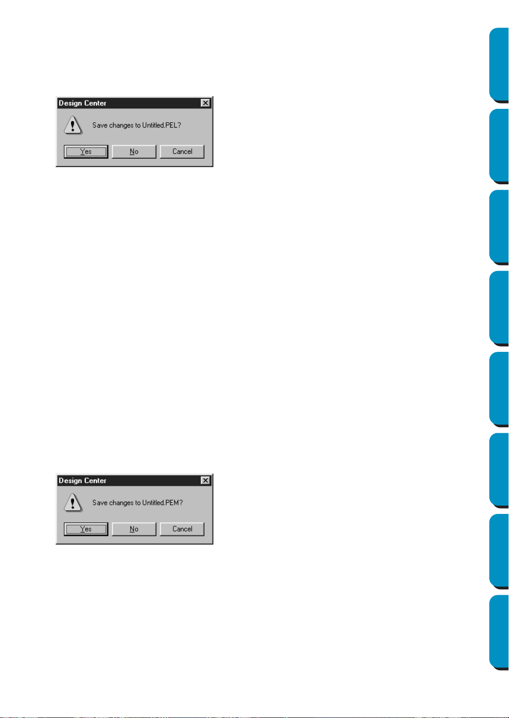
87
Contents Before Using Getting Started Design Center Layout & Editing
Programmable
Stitch Creator
Quick Reference Alphabetic Index
3 When the image transfer between the scanner (or other device) and the driver is complete, the
imported image will be pasted in Stage 1.
If you were editing a pattern on the design page before the transfer, you will be asked whether you
want to save the changes, for example:
NOTE:
TWAIN is an application interface (API) standardization for software controlling scanners, etc.
Also, the software itself is called TWAIN.
This software supports TWAIN standardized devices, so you can control the scanner and import
the image directly.
Before using this function, you must go to the “Select TWAIN device” dialog to select a TWAIN
device.
See also: “Select TWAIN device” on page 86
■ Input from Clipboard
Purpose: Opens a new design page in Stage 1, and puts the image data on the clipboard.
Shortcut key: No shortcut key for this function
Toolbar: No button for this function
Operation:
1 Click File, then Input from Clipboard. (This can only be done when there is image data on the clip-
board.)
If the current Design Page is not edited, the Stage 1 design page will open and will show the
image data as it was on the clipboard.
2 If the current Design Page is edited, you will be asked whether you want to save the changes, for
example:
3 Depending on the stage you are currently using and the editing you did, the file to be saved is a
*.pel file or a *.pem file or both.
See also: “Open” on page 85, “Save” and “Save As” on page 89
◆ Click Yes to save the Design Page first.
◆ Click No to abandon the Design Page.
◆ Click Cancel to do anything else (for
example, modify the current Design
Page or saving it with another file
name).
◆ Click Yes to save the Design Page first.
◆ Click
No to abandon the Design Page.
◆ Click
Cancel to do anything else (for
example, modify the current Design Page
or saving it with another file name).
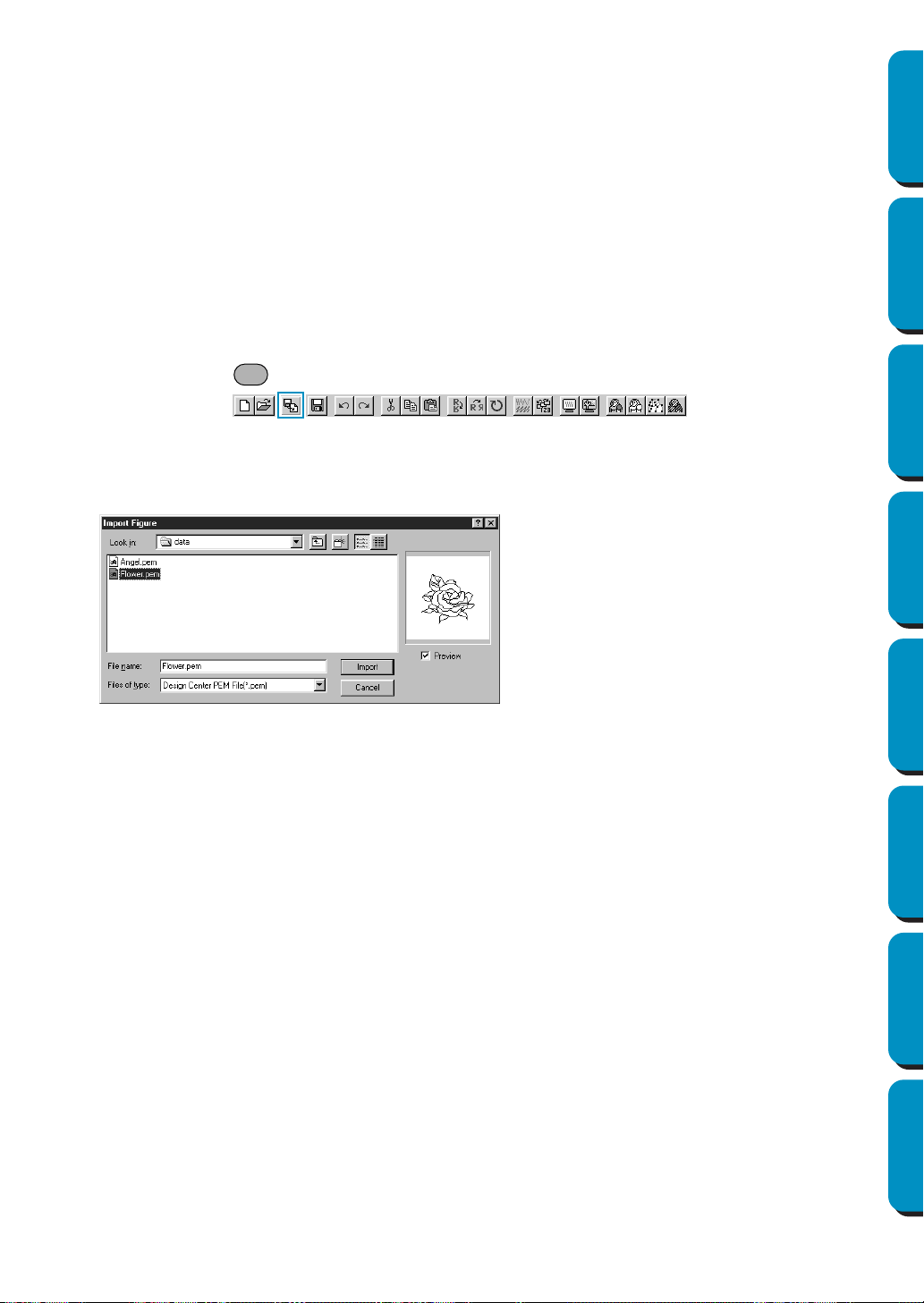
88
Contents Before Using Getting Started Design Center Layout & Editing
Programmable
Stitch Creator
Quick Reference Alphabetic Index
■ Output to Clipboard
Purpose: Copies the Stage 1 image data to the clipboard.
Shortcut key: No shortcut key for this function
Toolbar: No button for this function
Operation:
1 Click File, then Output to Clipboard. (This can only be done when there is image data in the Stage
1 design page.)
The image data in the design page is copied to the clipboard.
■ Import Figure
Purpose: Adds a *.pem file to your Design Page (available only in Stage 3).
Shortcut key:
Toolbar:
Operation:
1 Click File, then Import Figure.
A dialog similar to this will display.
The selected pattern will be added to your Design Page.
See also: “Open” on page 85
◆ Select the drive, the folder and the
file name.
◆ Click Import to open.
◆ Click
Cancel to exit.
F8
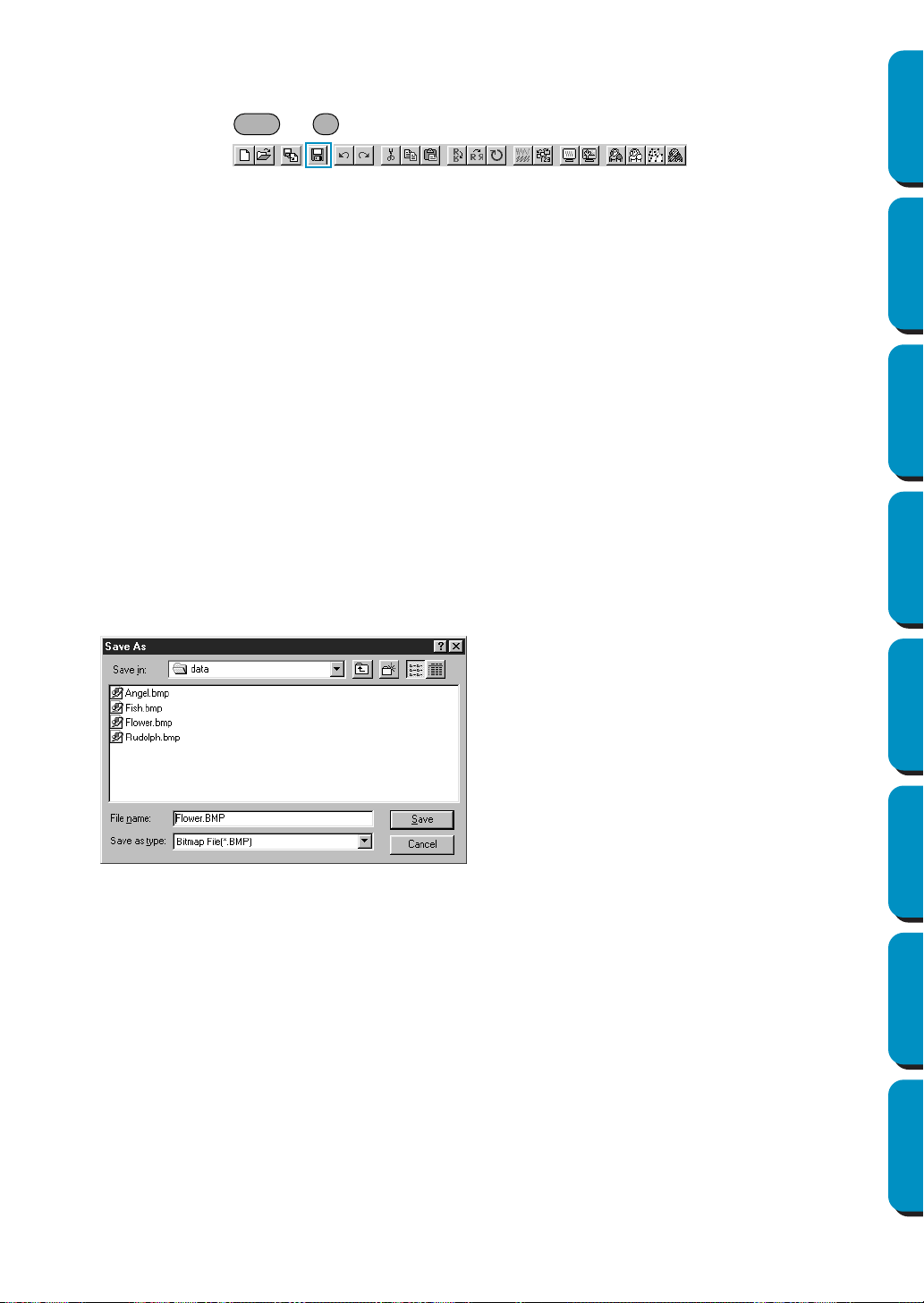
89
Contents Before Using Getting Started Design Center Layout & Editing
Programmable
Stitch Creator
Quick Reference Alphabetic Index
■ Save
Purpose: Saves your Design Page on the disk as latest Version file (default).
Shortcut key: +
Toolbar:
Operation:
1 Click File, then Save.
If the file already exists on the disk (the file has been saved at least once during the same stage as
the current one), the file is saved immediately.
2 If the file name is still Untitled or if, for any other reason, the file cannot be found on the disk, the
application automatically switches to
Save As.
See also: “Save As” below
■ Save As
Purpose: Saves the current file under a new file name.
Savable files are: in Stage 1, Bitmap files (*.bmp); in Stage 2, PEL files; and in
Stage 3 and 4, PEL and PEM files.
Shortcut key: No shortcut key for this function
Toolbar: No button for this function
Operation:
1 Click File, then Save As.
A
Save As dialog similar to this will display.
Stage1 image data can only be saved as a Bitmap file (*.bmp).
From Stage 2 to 4, black and white data can be saved as a PEL file, and pattern data can be
saved as a PEM file.
◆ Select the drive, the folder and type the
file name.
• The correct extension is automatically
set.
◆ Click Save to save.
◆ Click
Cancel to exit.
Ctrl S

90
Contents Before Using Getting Started Design Center Layout & Editing
Programmable
Stitch Creator
Quick Reference Alphabetic Index
2 If the new file name already exists, this dialog will appear.
See also: “Save” on page 89
NOTE:
If you select a previous version, saved *.pem files can be opened with a previous
version of the software. However, some information may be lost.
■ Exit
Purpose: Exits the application.
Shortcut key: +
Toolbar: No button for this function
Operation:
1 Click File, then Exit.
If the current Design Page is not edited, the application closes immediately.
2 If the current Design Page is edited, you will be asked whether you want to save the changes.
See also: “Save” and “Save As” on page 89
◆ Click
Yes to overwrite.
◆ Click No if you do not want to overwrite
the existing file.
Alt F4
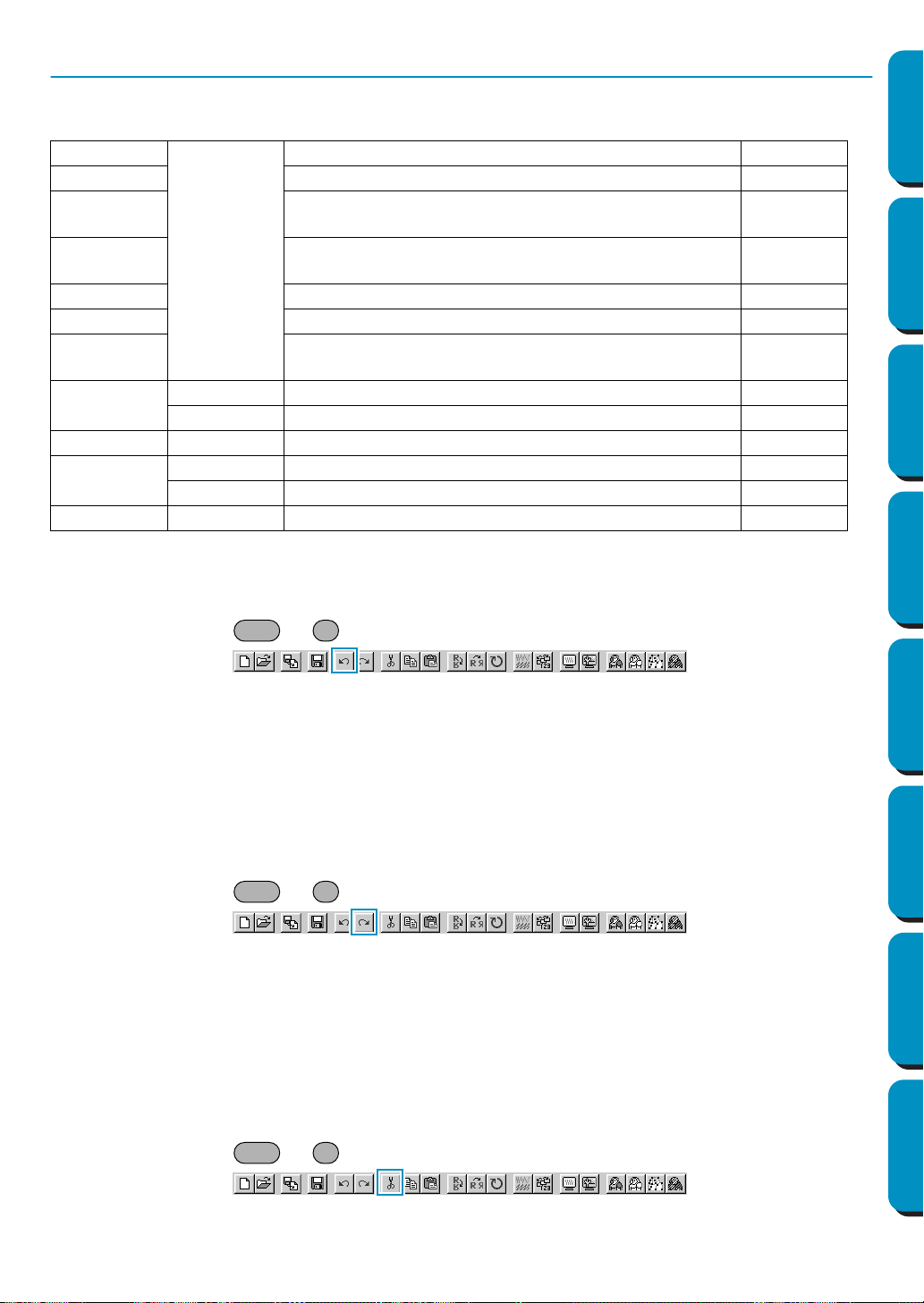
91
Contents Before Using Getting Started Design Center Layout & Editing
Programmable
Stitch Creator
Quick Reference Alphabetic Index
Edit Menu
The functions of the Edit menu perform simple actions on selected patterns, such as cutting and pasting.
■ Undo
Purpose: Undoes the last operation.
Shortcut key: +
Toolbar:
Operation:
1 Click Edit, then Undo.
The last operation is automatically undone.
See also: “Redo” below
■ Redo
Purpose: Cancels the effect of the last Undo.
Shortcut key: +
Toolbar:
Operation:
1 Click Edit, then Redo.
The effect of the last
Undo is cancelled.
See also: “Undo” above
■ Cut
Purpose: Removes the selected data from the screen while saving a copy in the clipboard.
Shortcut key: +
Toolbar:
Undo Undoes the last operation. page 91
Redo Cancels the effect of the last Undo. page 91
Cut
Removes the selected data from the screen while sav-
ing a copy in the clipboard.
page 91
Copy
Saves the selected data in the clipboard without remov-
ing them from the screen.
page 92
Duplicate Makes a copy of the selected data. page 92
Paste Pastes the contents of the clipboard on the screen. page 92
Delete
Removes the selected data from the screen without
saving them in the clipboard.
page 92
Mirror
Horizontal Flips the selected data up/down. page 93
Vertical Flips the selected data left/right. page 93
Rotate Allows you to change the direction of the pattern. page 94
Numerical
Setting
Size Resizes the selection numerically. page 94
Rotate Rotates the selected pattern numerically. page 95
Select All Selects all the data. page 95
Ctrl Z
Ctrl A
Ctrl X
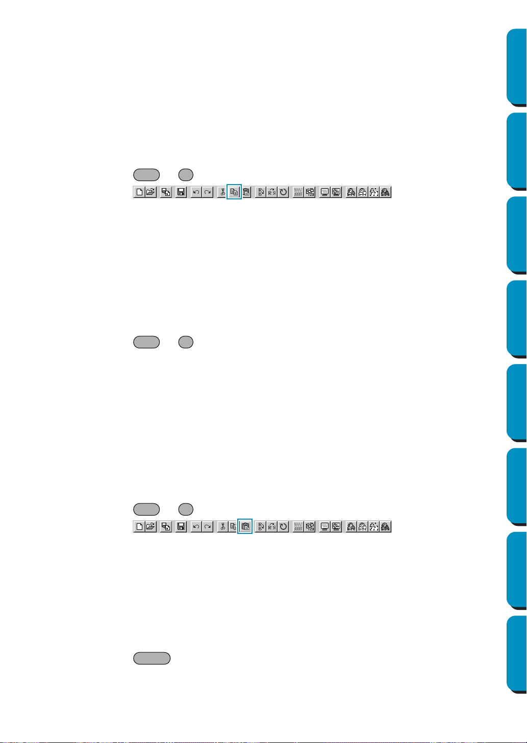
92
Contents Before Using Getting Started Design Center Layout & Editing
Programmable
Stitch Creator
Quick Reference Alphabetic Index
Operation:
1 Select one or more outline data (Stage 3 only).
2 Click Edit, then Cut.
The selected outline data disappear. Since they are saved in the clipboard, you can paste them
back using
Edit – Paste.
See also: “Copy”, “Paste” and “Delete” below
■ Copy
Purpose: Saves the selected data in the clipboard without removing them from the screen.
Shortcut key: +
Toolbar:
Operation:
1 Select one or more outline data (Stage 3 only).
2 Click Edit, then Copy.
The outline data are copied into the clipboard and are ready to be pasted.
See also: “Cut” on page 91, “Duplicate” and “Paste” below
■ Duplicate
Purpose: Makes a copy of the selected data.
Shortcut key: +
Toolbar: No button for this function
Operation:
1 Select one or more outline data (Stage 3 only).
2 Click Edit, then Duplicate.
A copy of the outline data appears on the screen.
See also: “Copy” above and “Paste” below
■ Paste
Purpose: Pastes the contents of the clipboard on the screen.
Shortcut key: +
Toolbar:
Operation:
1 Click Edit, then Paste (Stage 3 only).
The outline data saved in the clipboard (using Cut or Copy) are pasted on the screen.
See also: “Cut” on page 91, “Copy” and “Duplicate” above
■ Delete
Purpose: Removes the selected data from the screen without saving them in the clipboard.
Shortcut key:
Toolbar: No button for this function
Ctrl C
Ctrl D
Ctrl V
Delete
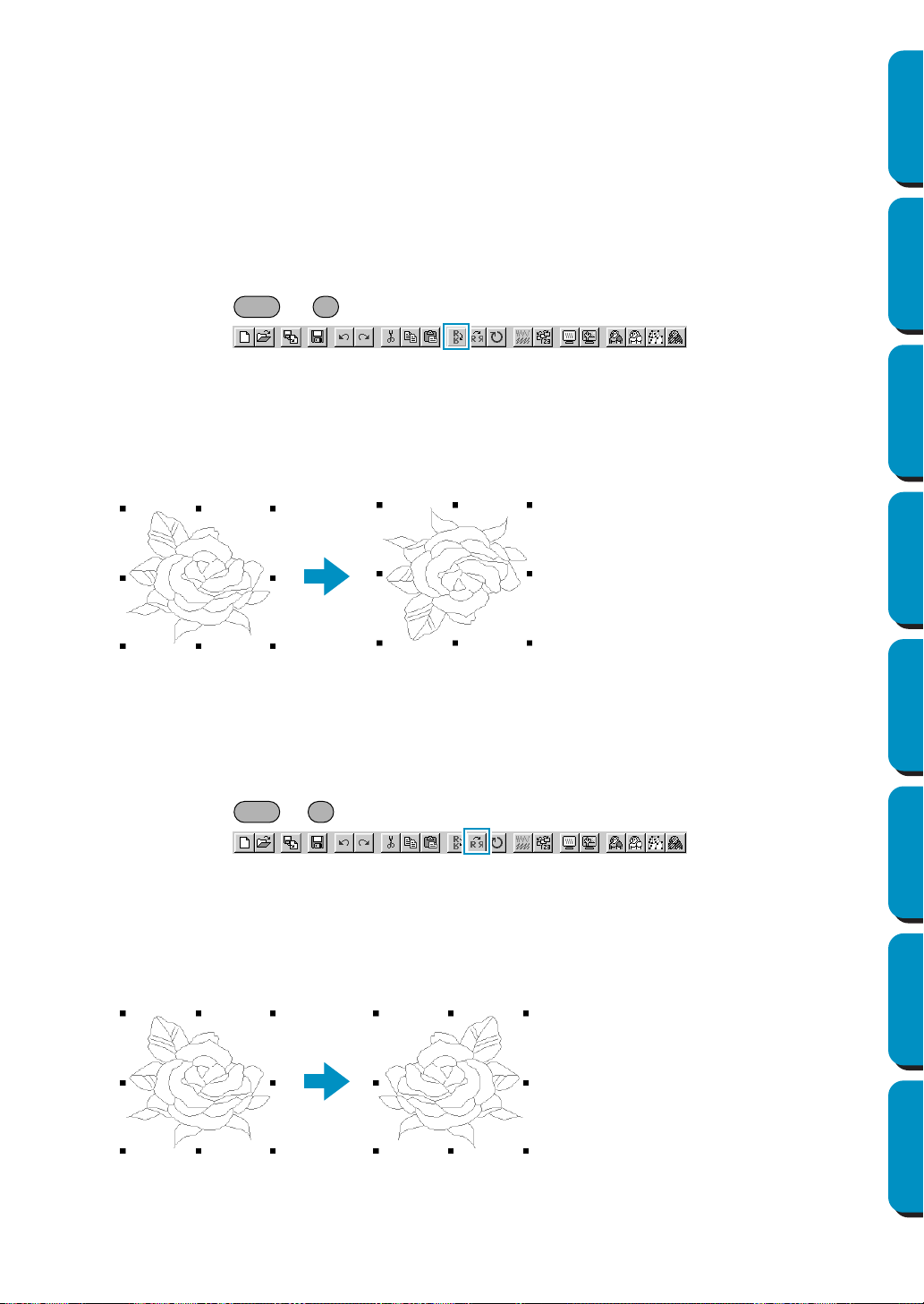
93
Contents Before Using Getting Started Design Center Layout & Editing
Programmable
Stitch Creator
Quick Reference Alphabetic Index
Operation:
1 Select one or more outline data (Stage 3 only).
2 Click Edit, then Delete.
The selected outline data are removed from the screen. Since they are not saved in the clipboard,
the only way to make them reappear is to use
Edit – Undo.
See also: “Undo” and “Cut” on page 91
■ Mirror – Horizontal
Purpose: Flips the selected data up/down.
Shortcut key: +
Toolbar:
Operation:
1 Select one or more outline data (Stage 3 only).
2 Click Edit, then Mirror, then Horizontal.
A horizontal mirror image (top and bottom inverted) of the outline data appears on the screen.
Two successive executions of this command restores the original image.
See also: “Flipping a pattern horizontally or vertically” on page 67 and “Mirror – Vertical”
below
■ Mirror – Vertical
Purpose: Flips the selected data left/right.
Shortcut key: +
Toolbar:
Operation:
1 Select one or more outline data (Stage 3 only).
2 Click Edit, then Mirror, then Vertical.
A vertical mirror image (left and right inverted) of the outline data appears on the screen.
Two successive executions of this command restores the original image.
See also: “Flipping a pattern horizontally or vertically” on page 67 and “Mirror – Horizontal”
above
Ctrl H
Ctrl J
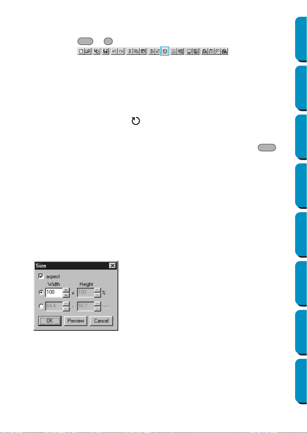
94
Contents Before Using Getting Started Design Center Layout & Editing
Programmable
Stitch Creator
Quick Reference Alphabetic Index
■ Rotate
Purpose: Allows you to change the direction of the pattern.
Shortcut key: +
Toolbar:
Operation:
1 Select one or more outline data (Stage 3 only).
2 Click Edit, then Rotate.
The handles around a selected pattern are replaced by smaller rectangle on the four corners of
the selected area.
3 To rotate a pattern, move the cursor on one of the four rotation handles.
The shape of the cursor changes to as soon as your cursor touches a rotation handle. Click
a handle and a lined box appears around the selected pattern.
You can rotate the pattern clockwise or counterclockwise by dragging the mouse.
A simple dragging of the mouse will rotate the pattern by 1˚ increments. Pressing the key
will rotate it by 15˚ increments.
See also: “Rotating a pattern” on page 67
■ Numerical Setting-Size
Purpose: Resizes the selection numerically.
Shortcut key: No shortcut key for this function.
Toolbar: No button for this function.
Operation:
1 Select one or more patterns. (Stage 3 only)
2 Click Edit, then Numerical Setting, then Size.
The
Size dialog appears.
◆ To change the width and height propor-
tionally, check aspect.
◆ Select the units (% or mm/inch) for the
width and height.
◆ Either typing in a value or clicking the
arrows to select the desired value can
enter the width and height.
Select 100% to leave the pattern
unchanged.
If aspect is selected, changing one
dimension automatically changes the
other so the proportion of the width and
height remains unchanged.
◆ Click
OK to confirm.
◆ Click Preview to view the pattern at the
new size in the Design Page.
◆ Click
Cancel to exit without making any
changes.
Ctrl Y
Shift
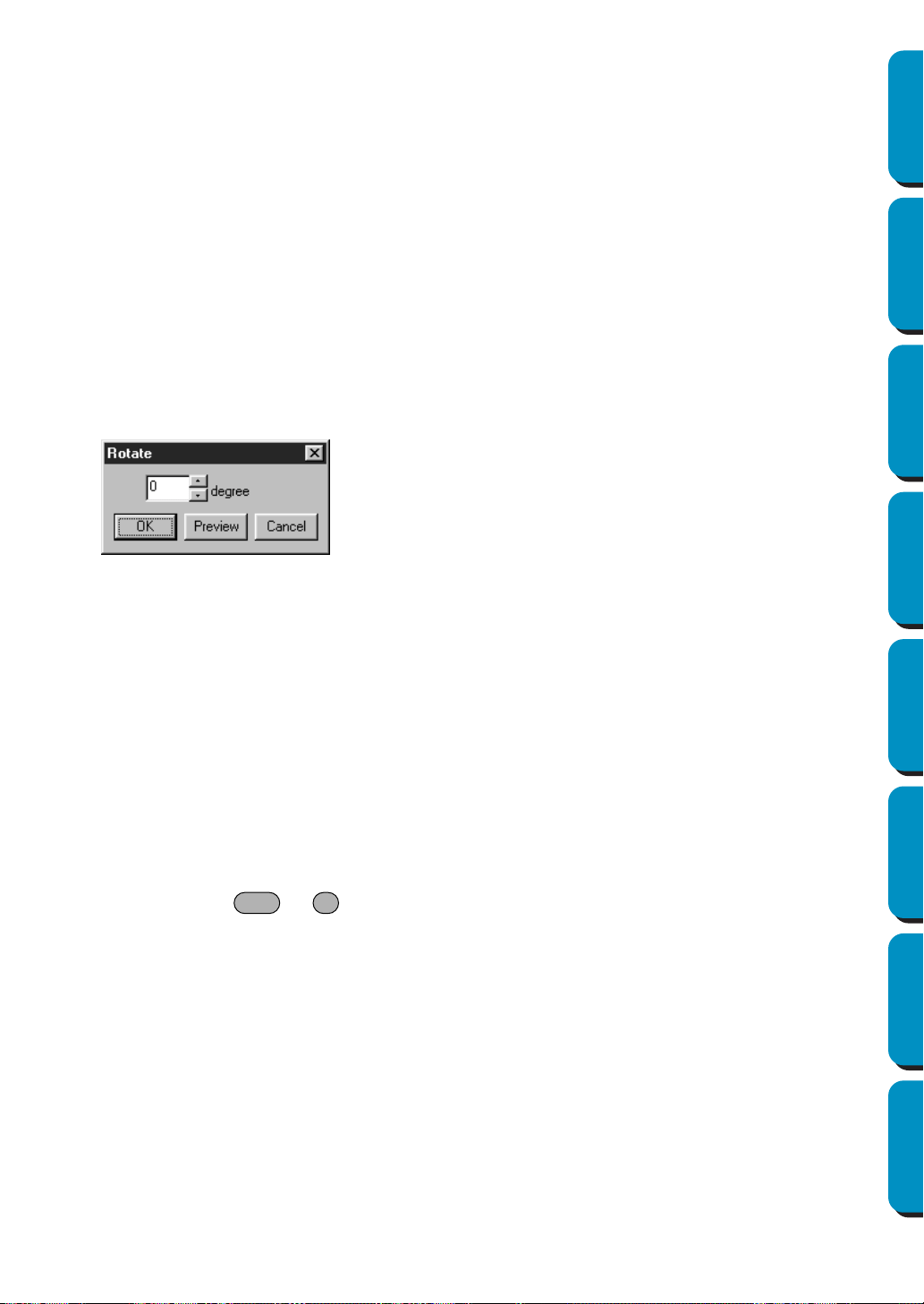
95
Contents Before Using Getting Started Design Center Layout & Editing
Programmable
Stitch Creator
Quick Reference Alphabetic Index
NOTE:
The maximum value that can be entered is the largest value that will not allow the pattern to
exceed the size of the Design Page.
The minimum value is 1 mm (0.04 inch).
See also: “Select System Unit” on page 107
■ Numerical Setting-Rotate
Purpose: Rotates the selected pattern numerically.
Shortcut key: No shortcut key for this function.
Toolbar: No button for this function.
Operation:
1 Select one or more patterns. (Stage 3 only)
2 Click Edit, then Numerical Setting, then Rotate.
The Rotate dialog appears.
NOTE:
The range of values that can be entered is between 0 and 359 degrees, in 1-degree increments.
■ Select All
Purpose: Selects all the data.
Shortcut key: +
Toolbar: No button for this function
Operation:
1 Click Edit, then Select All (Stage 3 only).
◆ The desired rotation angle can be
entered by either typing in a value or
clicking the arrows to select the desired
value.
Select 0 degree to leave the pattern
unchanged.
◆ Click OK to confirm.
◆ Click
Preview to view the pattern
rotated the specified angle in the
Design Page.
◆ Click Cancel to exit without making any
changes.
Ctrl E
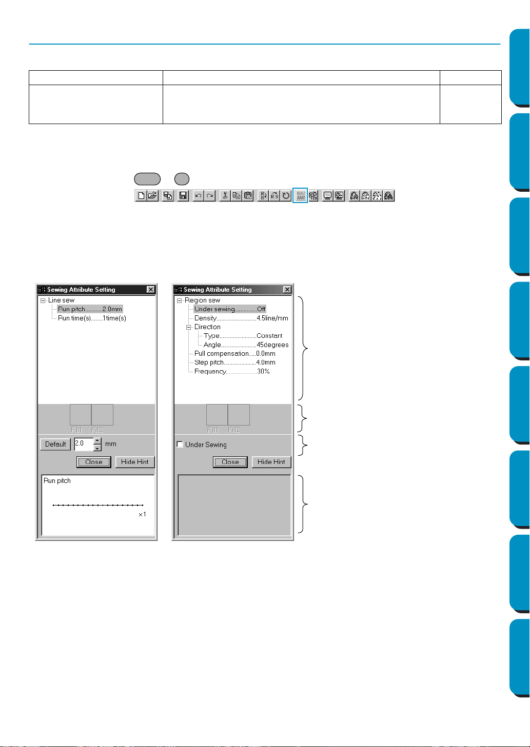
96
Contents Before Using Getting Started Design Center Layout & Editing
Programmable
Stitch Creator
Quick Reference Alphabetic Index
Sew Menu
The Sew menu allows you to control the way the pattern will be sewn.
■ Sewing Attributes
Purpose: Sets the sewing attributes for outlines and regions.
Shortcut key: +
Toolbar:
Operation:
1 Click Sew, then Sewing Attribute.
A Sewing Attribute dialog similar to this will display.
You can freely change the size of this dialog.
When in Line Sewing Mode, only Line sewing items are displayed. When in Region Sewing Mode,
only Region sewing items are displayed.
A: Sewing attribute display area: Displays the present settings for each of the sewing attributes.
B: Selected pattern display area: When a pattern for Programmable Fill or Motif sewing is
selected, that pattern is displayed.
C: Edit box: Displays the setting values to be changed for the item selected
in the Sewing attribute display area.
D: Hint image display area: When set to display a hint, a hint image showing the settings in
the edit box is displayed.
Sewing Attributes Sets the sewing attributes for outlines and regions. page 96
Sewing Order
Allows you to check and modify the sewing order of the dif-
ferent colors of a pattern as well as the sewing order of
each color individually.
page 100
◆ Select the item you want to change
or set in the Sewing attribute dis-
play area (A), then enter the change
or setting in the Edit box. (C)
◆ The method for entering the set-
ting varies according to the item. If
entering numerical values, you can
click on the arrow buttons to select
values or enter the values directly.
If the Default button is displayed in
the Edit box (C), click the button to
apply the Default setting to the
selected item.
◆ When in Line Sewing Mode, click
on the outline to apply the contents
of the settings to the outline.
When in Region Sewing Mode,
click on the region to apply the con-
tents of the settings to the region.
◆ Click Close to exit.
◆ Click Show Hint/Hide Hint to turn
the hint image display on or off (D).
Ctrl W
For Line Sewing Mode
For Region Sewing Mode
A
B
C
D
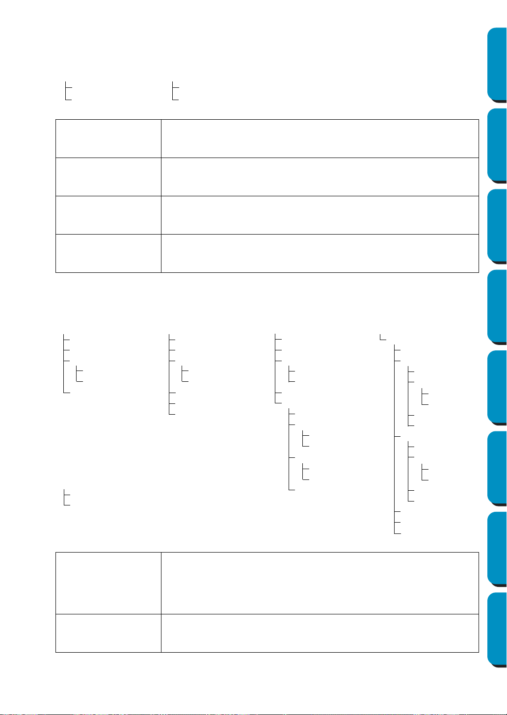
97
Contents Before Using Getting Started Design Center Layout & Editing
Programmable
Stitch Creator
Quick Reference Alphabetic Index
Line sewing attribute
Setting items according to the selected stitch
Zigzag stitch
Line sewing
Zigzag width
Density
Running stitch
Line sewing
Run pitch
Run times
Zigzag width
Sets the width of the zigzag.
Range: 1 - 10 mm (0.04 - 0.39 inch)
Default: 2 mm (0.08 inch)
Density
Sets the number of lines per mm (inch).
Range: 1 - 7 lines per mm (25 - 178 lines per inch)
Default: 4.5 lines per mm (114 lines per inch)
Run pitch
Sets the pitch of the line sewing.
Range: 1 - 10 mm (0.04 - 0.39 inch)
Default: 2 mm (0.08 inch)
Run times
Sets the number of times the border will be sewn.
Range: 2, 4, 6
Default: 2
Region sewing attribute
Setting items according to the selected stitch
Satin stitch
Region sewing
Under sewing
Density
Direction
Type
Angle
Pull compensation
Fill stitch
Region sewing
Under sewing
Density
Direction
Type
Angle
Pull compensation
Step pitch
Frequency
Programmable fill
Region sewing
Under sewing
Density
Direction
Type
Angle
Pull compensation
Programmable Fill
Pattern
Pattern size
Width
Height
Offset
Direction
Value
Direction
Motif stitch
Region sewing
Motif
Use Pattern
Pattern1
Pattern
Pattern size
Width
Height
H-Arrange
V-Arrange
Pattern2
Pattern
Pattern size
Width
Height
H-Arrange
V-Arrange
Row offset
Direction
Run pitch
Cross stitch
Size
Times
Under Sewing
Sets Under Sewing on/off. Try to use Under Sewing for wide areas, in order
to prevent shrinking during stitching. Depending on the shape of the region,
however, it may not be possible to make this setting.
On: Under Sewing will be done
Off: Under Sewing will not be done
Density
Sets the number of lines per mm.
Range: 1 - 7 lines per mm (25 - 178 lines per inch)
Default: 4.5 lines per mm (114 lines per inch)
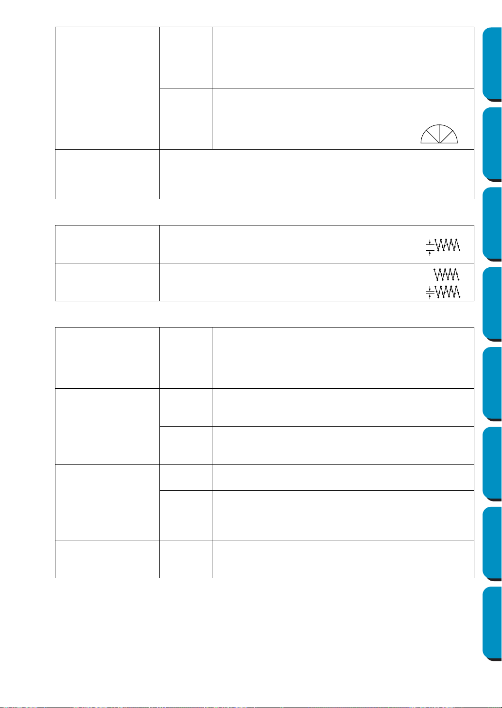
98
Contents Before Using Getting Started Design Center Layout & Editing
Programmable
Stitch Creator
Quick Reference Alphabetic Index
Direction
Type
Specifies the type of sewing direction.
Constant: Sews at a fixed angle. The angle is specified by the
Angle setting.
Variable: Varies the sewing direction according to the object
being sewn.
Angle
Specifies the sewing angle.
(If
Variable is selected as the Type setting, this setting is not
available.)
Range: 0 - 179 degrees
Default: 45 degrees
Pull Compensation
Lengthens the sewing region in the stitch pattern’s sewing direction to pre-
vent pattern shrinkage during sewing.
Range:0 - 2 mm (0.00 - 0.08 inch)
Default:0 mm (0.00 inch)
Fill stitch only:
Step Pitch
Sets the pitch of the steps.
Range: 1 - 10 mm (0.04 - 0.39 inch)
Default: 4.0 mm (0.16 inch)
Frequency
Sets the spacial frequency steps.
Range: 0 - 99%
Default: 30%
Programmable fill stitch only:
Pattern
Select a pattern for Programmable Fill Stitch.
Click Select Pattern, and the Browse dialog opens. Select the
folder containing the pas file you want to open. Scroll through
the available stitch patterns and double-click the desired pat-
tern or click OK to select the pattern.
Pattern Size
Width
Sets the stitch pattern width.
Range: 5 - 10 mm (0.20 - 0.39 inch)
Default: 7.5 mm (0.30 inch)
Height
Sets the stitch pattern height.
Range: 5 - 10 mm (0.20 - 0.39 inch)
Default: 7.5 mm (0.30 inch)
Offset
Direction
Sets the offset arrangement of the pattern, and sets the direc-
tion of offset as Row/Column.
Value
When the pattern’s arrangement is offset, sets the amount of
offset.
Range: 0 - 99%
Default: 0%
Pattern Direction
Allows you to rotate the angle of the stitch patterns.
Range: 0 - 359 degrees
Default: 0 degrees
0˚
45˚
90˚
135˚
179˚
Step pitch
0%
30%
99
Contents Before Using Getting Started Design Center Layout & Editing
Programmable
Stitch Creator
Quick Reference Alphabetic Index
Motif stitch only:
Use Pattern
Selects whether to use pattern 1 or pattern 2 for Motif. If you
choose to use both patterns, the data is created so that sewing
is alternated between them after each row.
Pattern1 only: Uses only pattern 1 (Default)
Pattern2 only: Uses only pattern 2
Pattern1 and 2: Uses pattern 1 and pattern 2
Pattern
Select a pattern for Motif sewing.
Click Select Pattern, and the Browse dialog will display. Select
the folder containing the pmf file you want to open. Scroll
through the available stitch patterns and double-click the
desired pattern or click OK to select the pattern
Pattern Size
Width
Sets the pattern width (the direction along the line).
Range: 2 - 10 mm (0.08 - 0.39 inch)
Default: 5 mm (0.20 inch)
Height
Sets the pattern height (the direction perpendicular to the line).
Range: 2 - 10 mm (0.08 - 0.39 inch)
Default: 5 mm (0.20 inch)
H-Arrange
(Horizontal Arrange)
Sets the horizontal arrangement of the
pattern. For patterns like , patterns will
be arranged along the line as shown to the
right.
V-Arrange
(Vertical Arrange)
Sets the vertical arrangement of the pat-
tern. For patterns like , patterns will be
arranged along the line as shown to the
right.
Row Offset
When the pattern arrangement is offset, sets the amount of
offset for each row.
Range: 0 - 10 mm (0.00 - 0.39 inch)
Default: 0 mm (0.00 inch)
Direction
Allows you to rotate the angle of the Motif patterns.
Range: 0 - 359 degrees
Default: 0 degrees
Run Pitch
Sets the pitch of the sewing.
Range: 1 - 10 mm (0.04 - 0.39 inch)
Default: 2 mm (0.08 inch)
Cross stitch only:
Size
Sets the horizontal and vertical size of the pattern.
Range: 1.5 - 5 mm (0.06 - 0.20 inch)
Default: 2.5 mm (0.10 inch)
Times
Sets the number of times that the pattern will be sewn. Sews
twice per time.
Range: Single, Double, Triple
Default: Single
Normal:
Mirror:
Alternate:
Normal:
Mirror:
Alternate:
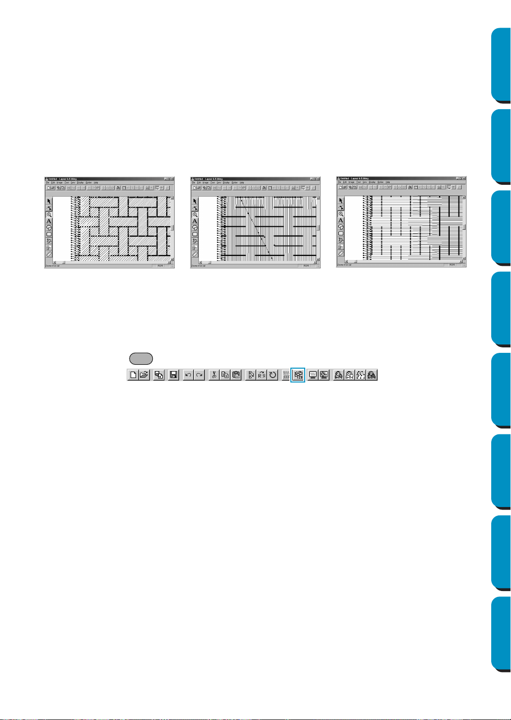
100
Contents Before Using Getting Started Design Center Layout & Editing
Programmable
Stitch Creator
Quick Reference Alphabetic Index
Note on the Programmable Fill Stitch:
When setting the stitch and pattern directions of a programmable stitch, take note that whenever
the stitch and pattern direction settings cause the stitch to be sewn in the same direction as a line
in a stitch pattern, that line will not be sewn.
Use the preview function of your application to view exactly how your stitch pattern will be sewn
and set the stitch direction and pattern direction according to the selected stitch or to the effect
that you want to produce. To get an even better view, make test samples of different settings.
Example of a programmable fill stitch:
See also: “Preview” on page 104, “Programmable Stitch Creator” on page 233
■ Sewing Order
Purpose: Allows you to check and modify the sewing order of the different colors of a pat-
tern as well as the sewing order of each color individually.
Shortcut key:
Toolbar:
Operation:
1 Click Sew, then Sewing Order.
The Sewing Order dialog opens and displays the Color tab. The embroidery pattern is grayed.
Example 2:
Stitch direction: 90˚
Example 1:
Stitch direction: Default: 45˚
Example 3:
Stitch direction: 0˚
F10

101
Contents Before Using Getting Started Design Center Layout & Editing
Programmable
Stitch Creator
Quick Reference Alphabetic Index
2 To check and review the sewing order of the different colors of a pattern:
Make sure the
Color tab is displayed.
◆ Click . The color that will be sewn first
displays.
◆ Click or to review the colors that
will be sewn between the first and last.
• As you click , , , or ,
the corresponding colors display.
◆ Click to see the color that will be sewn
last.
◆ Click if you want the selected color to
be sewn last.
◆ Click if you want the selected color to
be sewn first.
◆ Click to move the selected color back
one spot in the sewing order.
◆ Click to move the selected color for-
ward one spot in the sewing order.
◆ Click OK to confirm.
◆ Click Cancel to exit.
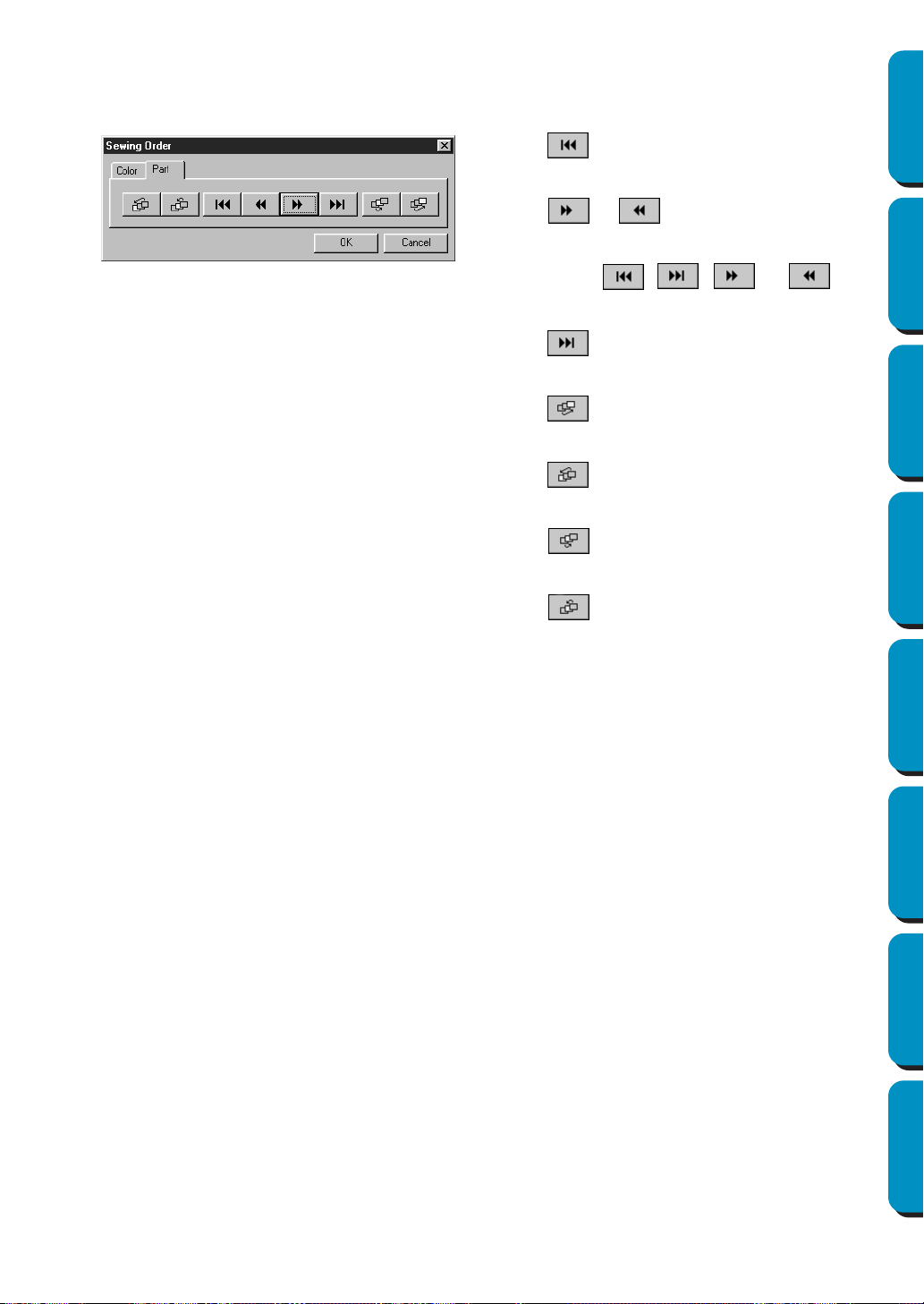
102
Contents Before Using Getting Started Design Center Layout & Editing
Programmable
Stitch Creator
Quick Reference Alphabetic Index
3 To check and review the sewing order of the parts of the same color, select a color in the Color tab,
then click the
Part tab.
The parts to which you attributed the selected color are displayed in gray.
Note that all inside regions are always sewn before the outlines. If you set an outline to be sewn
first, it will be the first outline to be sewn, but will still be sewn after all inside regions.
See also: “Preview” on page 104
◆ Click . The part that will be sewn first
displays.
◆ Click or to review the parts that
will be sewn between the first and last.
• As you click , , , or ,
the corresponding parts display.
◆ Click to see the part that will be sewn
last.
◆ Click if you want the selected part to be
sewn last.
◆ Click if you want the selected part to be
sewn first.
◆ Click to move the selected part one
spot back in the sewing order.
◆ Click to move the selected part one
spot forward in the sewing order.
◆ Click OK to confirm.
◆ Click Cancel to exit.
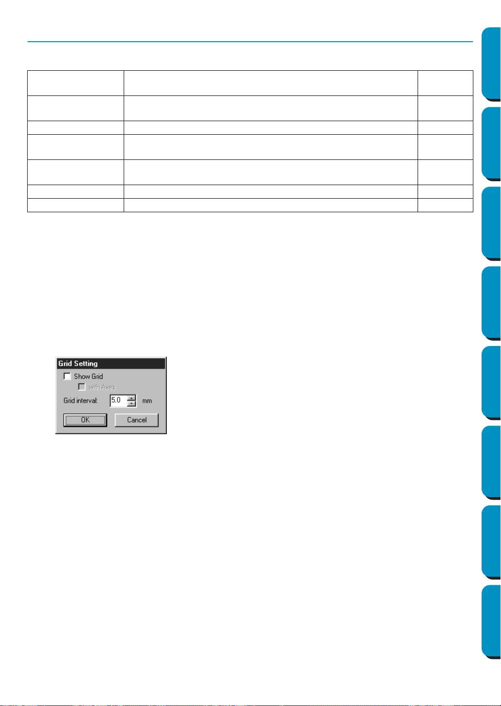
103
Contents Before Using Getting Started Design Center Layout & Editing
Programmable
Stitch Creator
Quick Reference Alphabetic Index
Display Menu
The Display menu lets you modify the appearance of the screen.
■ Grid Setup
Purpose: Allows you to set up the grid, to switch it on or off and to display it with or without
the horizontal and vertical lines.
Shortcut key: No shortcut key for this function
Toolbar: No button for this function
Operation:
1 Click Display, then Grid Setup (Stage 3 only).
This dialog displays.
2 To set the grid interval, click the up and down arrows or type in the value.
Setting range: 1 - 10 mm (0.04 - 0.39 in)
Click OK to confirm or Cancel to exit.
3 To switch the grid on or off, click the Show grid check box.
The grid will display when the
Show grid check box is checked.
4 To switch the horizontal and vertical lines of the grid on and off, click the with Axes check box.
The lines will display when the
with Axes check box is checked.
NOTE:
When the Show grid check box is checked and the with Axes check box is not checked, only the
intersection points of the grid will be displayed.
See also: “Select System Unit” on page 229
Grid Setup
Allows you to set up the grid, to switch it on or off and to display it
with or without the horizontal and vertical lines.
page 103
Preview
Displays a realistic image of how the patterns will look like when
embroidered.
page 104
Refresh Window Updates the screen. page 104
Realistic Preview
Displays a realistic image of how either selected patterns or all
patterns will look after being embroidered.
page 104
Realistic Preview
Attribute Setting
Sets the preview attributes for Realistic Preview. page 104
Toolbar Turns the Toolbar on/off. page 105
Status Bar Turns the Status bar on/off. page 105
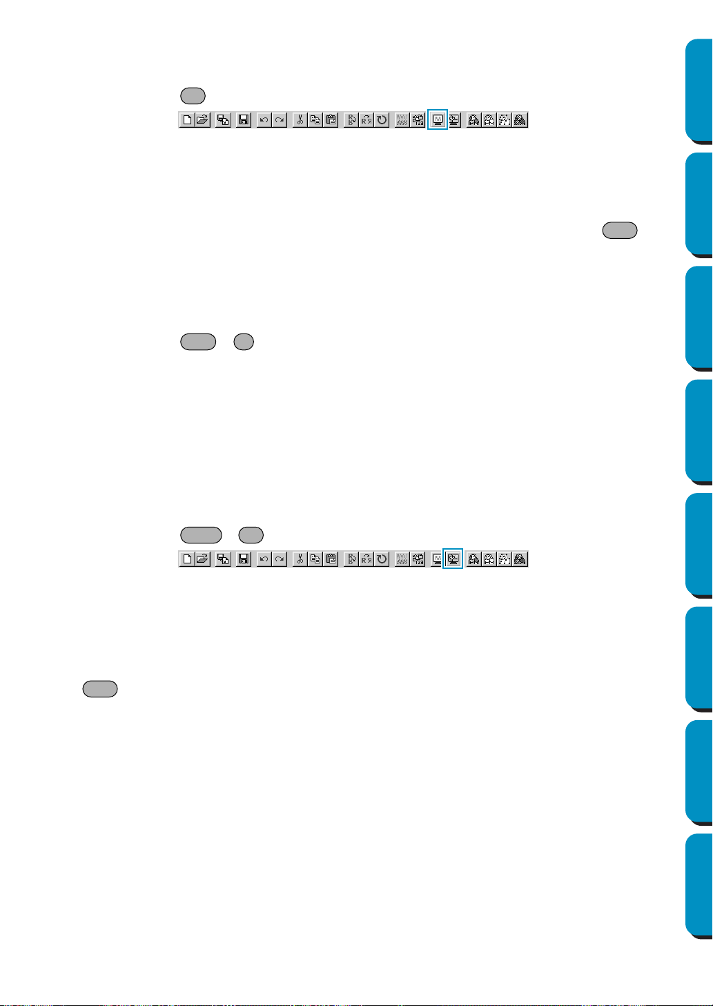
104
Contents Before Using Getting Started Design Center Layout & Editing
Programmable
Stitch Creator
Quick Reference Alphabetic Index
■ Preview
Purpose: Displays a realistic image of how the patterns will look like when embroidered.
Shortcut key:
Toolbar:
Operation:
1 Click Display, then Preview (Stage 4 only).
A preview of your embroidery patterns will appear.
You cannot make any settings while previewing a pattern.
2 To return to the normal working screen, click Display, then Preview again or press the key.
See also: “Sewing Order” on page 100
■ Refresh Window
Purpose: Updates the screen.
Shortcut key: +
Toolbar: No button for this function
Operation:
1 Click Display, then Refresh Window.
Use this function when the screen does not seem to update correctly.
■ Realistic Preview
Purpose: Displays a realistic image of how either selected patterns or all patterns will look
after being embroidered.
Shortcut key: +
Toolbar:
Operation:
1 Click Display, then Realistic Preview (Stage 4 only).
The patterns on the Design Page are displayed realistically according to the settings in the Realis-
tic Preview Attribute Setting dialog.
2 To return to the normal working screen, click Display, then Realistic Preview again or press the
key.
NOTE:
The Realistic Preview function cannot display a beautiful preview of the pattern if the monitor is set
to 256 colors or less. The monitor should be set to at least 16-bit High Color (65536 colors).
See also: “Realistic Preview Attribute Setting” below
■ Realistic Preview Attribute Setting
Purpose: Sets the preview attributes for Realistic Preview.
Shortcut key: No shortcut key for this function
Toolbar: No button for this function
F9
Esc
Ctrl R
Shift F9
Esc
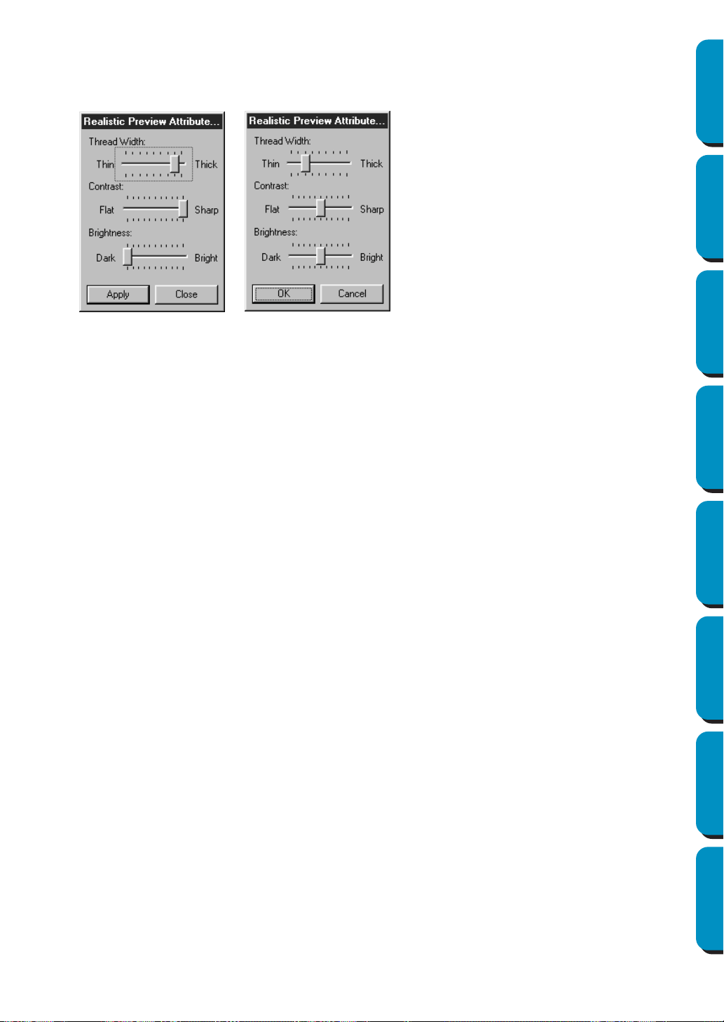
105
Contents Before Using Getting Started Design Center Layout & Editing
Programmable
Stitch Creator
Quick Reference Alphabetic Index
Operation:
1 Click Display, then Realistic Preview Attribute Setting (Stage 4 only).
The following dialog appears.
See also: “Realistic Preview” on page 104
■ Toolbar
Purpose: Turns the Toolbar on/off.
Shortcut key: No shortcut key for this function
Toolbar: No button for this function
Operation:
1 Click Display, then Toolbar.
The Toolbar will be toggled on/off.
See also: “Status Bar” below
■ Status Bar
Purpose: Turns the Status bar on/off.
Shortcut key: No shortcut key for this function
Toolbar: No button for this function
Operation:
1 Click Display, then Status bar.
The Status bar will be toggled on/off.
See also: “Toolbar” above
◆ Use Thread Width to set how wide the
thread will appear.
◆ Use Contrast to set the contrast.
◆ Use Brightness to set how bright the
display is.
◆ Click Apply to display a Realistic Pre-
view of the patterns with the new set-
tings. (When Realistic Preview is
displayed)
Or, click OK to save the settings for the
next time Realistic Preview is dis-
played. (When Realistic Preview is not
displayed)
◆ Click Close or Cancel to exit.
106
Contents Before Using Getting Started Design Center Layout & Editing
Programmable
Stitch Creator
Quick Reference Alphabetic Index
Option Menu
The Option menu allows you to select the Design Page size and the unit system.
■ Layout & Editing
Purpose: Starts Layout & Editing and displays its window up front.
Shortcut key:
Toolbar: No button for this function
Operation:
1 Click Option, then Layout & Editing.
Layout & Editing starts if its window wasn’t open and if it was open, the window comes up front.
■ Programmable Stitch Creator
Purpose: Starts Programmable Stitch Creator and displays its window up front.
Shortcut key: No shortcut key for this function
Toolbar: No button for this function
Operation:
1 Click Option, then Programmable Stitch Creator.
Programmable Stitch Creator starts if its window wasn’t open and if it was open, the window
comes up front.
■ Design Page Property
Purpose: Allows you to change the size of the Design Page and the color of the Design
Page and the Design Page background.
Shortcut key: No shortcut key for this function
Toolbar: No button for this function
Layout & Editing Starts Layout & Editing and displays its window up front. page 106
Programmable Stitch
Creator
Starts Programmable Stitch Creator and displays its win-
dow up front.
page 106
Design Page Property
Allows you to change the size of the Design Page and the
color of the Design Page and the Design Page back-
ground.
page 106
Select System Unit Allows you to select the system unit (mm or inch). page 107
F5
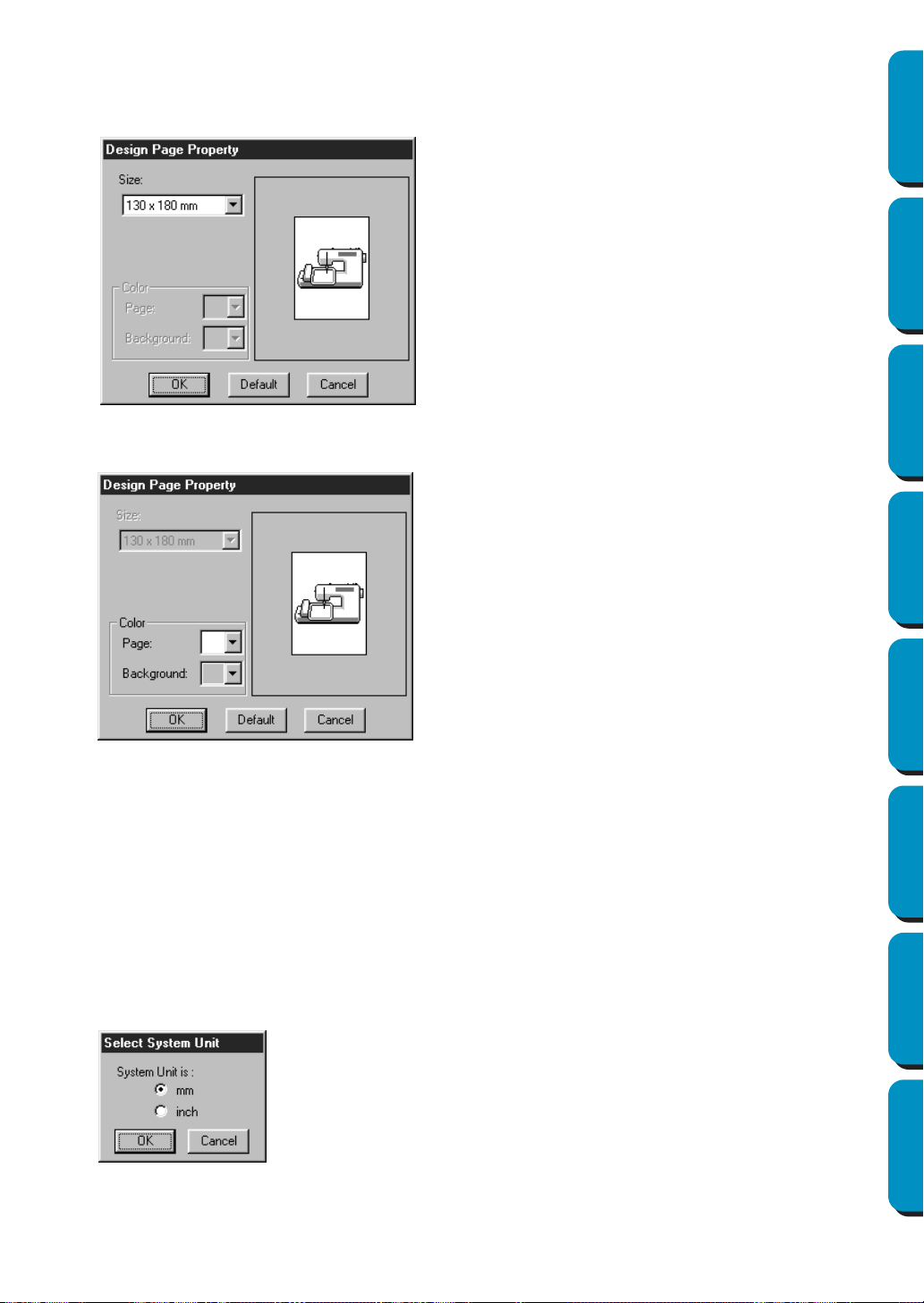
107
Contents Before Using Getting Started Design Center Layout & Editing
Programmable
Stitch Creator
Quick Reference Alphabetic Index
Operation:
1 Click Option, then Design Page Property.
At the Stage 3 only, the dialog will display as follows.
At the Stage 4 only, the dialog will display as follows.
See also: “Select System Unit” below
■ Select System Unit
Purpose: Allows you to select the system unit (mm or inch).
Shortcut key: No shortcut key for this function
Toolbar: No button for this function
Operation:
1 Click Option, then Select System Unit.
This dialog will display.
◆ Select the size by clicking its selector arrow,
then by clicking the size.
The preview area allows you to view the setting
changes. The sewing machine picture shows
the direction of the Design Page (frame) on the
machine.
◆ Click OK to confirm.
◆ Click Default to go back to the default setting.
◆ Click Cancel to exit.
◆ Select the Page color or the Background color
by clicking its selector arrow, then by clicking
the color.
The preview window allows you to view the
selected colors.
◆ Click
OK to confirm.
◆ Click Default to go back to the default setting.
◆ Click
Cancel to exit.
◆ Select the unit.
◆ Click
OK to confirm.
◆ Click Cancel to exit.
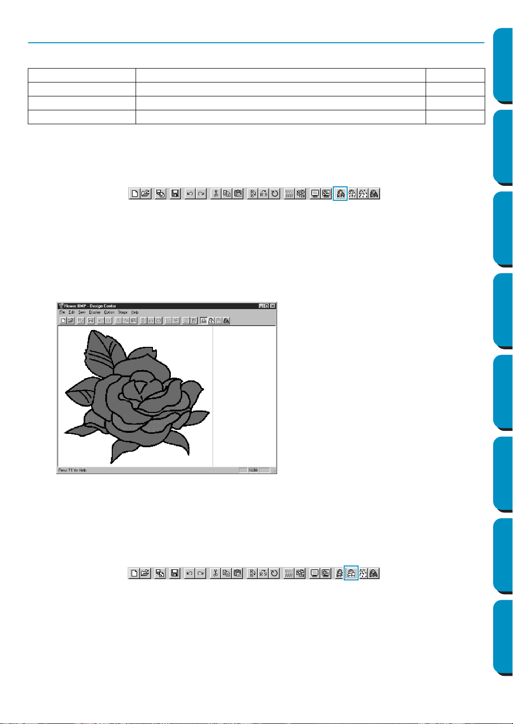
108
Contents Before Using Getting Started Design Center Layout & Editing
Programmable
Stitch Creator
Quick Reference Alphabetic Index
Stage Menu
The Stage menu allows you to move from one stage to the next or previous one.
■ To Original Image
Purpose: Moves back to Stage 1.
Shortcut key: No shortcut key for this function
Toolbar:
Operation:
1 Click Stage, then To Original Image.
You are back to Stage 1 (the original color image displays).
NOTE:
This function can only be used if there was image data in Stage 1 (if image data was opened, if
image data was pasted from the clipboard, etc.)
If you have started with a new file (Stage 2), for example, the function is not enabled.
See also: “To Line Image” below, “To Figure Handle” on page 110, “To Sew Setting” on page
112
■ To Line Image
Purpose: Moves to Stage 2.
Shortcut key: No shortcut key for this function
Toolbar:
Operation:
1 Click Stage, then To Line Image.
If you were in Stage 3, you are returned to Stage 2, except when you have modified the image in
Stage 3. In that case, a message will ask you to confirm that you want to abandon the changes
made in Stage 3.
To Original Image Moves back to Stage 1. page 108
To Line Image Moves to Stage 2. page 108
To Figure Handle Moves to Stage 3. page 110
To Sew Setting Moves from Stage 3 to Stage 4. page 112

109
Contents Before Using Getting Started Design Center Layout & Editing
Programmable
Stitch Creator
Quick Reference Alphabetic Index
NOTE:
If you started in Stage 3 by opening a Stage 3 file, you cannot go to Stage 2.
[Color Reduction function]
If you click the Image Tune button in the above dialog, a Image Tune dialog similar to this will display,
and you can reduce the colors of the image data (posterize) or reduce the noise.
With this function, you can apply an even gradation to make the image smoother. You can use Pick
Colors
to select colors easily, even from image data that was taken from a scanner or other device,
and does not have clear outlines.
NOTE:
This operation is done so that the operations in the Cut Out to Line Image dialog can be done, so
the image that results from these operations cannot be saved.
◆ If necessary, scroll and zoom the image.
◆ Select the color(s) that you want to convert into
black. To do this, move the cursor over the
image. The shape changes to . Click on a
color. The color moves to the upper box under
Pick Colors and a appears in the check box
to show that the color is on. You can repeat to
select a total of five colors. If you try to select
more, colors are scrolled down, and the color
that was at the bottom is deselected.
• If you selected a color by mistake, simply click
its check box to deselect it.
◆ Click View to see the effect of your selection.
You can repeat this step after clicking on the
check boxes of the selected colors to toggle
them on/off, or after selecting different colors.
◆ Click OK to confirm.
◆ Click Cancel to exit.
◆ Image Window displays the image
resulting from the current operations.
◆
Tone sets the amount of color reduc-
tion (posterization). The right side
(High) shows the original image. The
farther to the left side (Low) the setting
is made, the greater the amount of
color reduction.
◆ If Noise Reduction is checked, the very
small areas of noise are deleted.
◆
Click
OK
to show the finished image on
the Design Page and on the Cut Out to
Line Image dialog, and close the dialog.
Before you open this dialog, the Pick
Colors that were picked out in the Cut
Out to Line Image dialog are reset.
◆ Click
Cancel to close the dialog.
Image Window
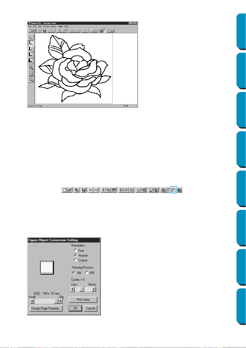
110
Contents Before Using Getting Started Design Center Layout & Editing
Programmable
Stitch Creator
Quick Reference Alphabetic Index
2 When you click OK, the black and white image is displayed and you are in Stage 2.
Note that all the colors that you selected and turned on are converted to black. It is recommended
to select just as many colors as necessary to have a good outline of the image. In the above exam-
ple, a single color was selected.
In Stage 2, you can edit the image using the pens and erasers and use the zooming tools.
Note that if you do not like the result, you can go back to Stage 1 and select different colors.
See also: “To Original Image” on page 108, “To Figure Handle” below and “To Sew Setting”
on page 112
■ To Figure Handle
Purpose: Moves to Stage 3.
Shortcut key: No shortcut key for this function
Toolbar:
Operation:
1 Click Stage, then To Figure Handle.
If you were in Stage 4, a message warns you that may lose some data if you go back to Stage 3. If
you want to make sure no data is lost, click
Cancel in that dialog and save your settings. Other-
wise, click OK and you are returned to Stage 3.
If you were in Stage 2, this dialog displays.
◆ Set the resolution. For details, see the following
table.
◆ Set the thinning process. For details, see the
following table.
◆ Set the size as a percentage of the original using
the SIZE slider (setting range: 25% - 400 %). You
will not be able to enlarge the image beyond the
limits of the Design Page area. If necessary, set
the Design Page size by clicking Design Page
Property
and selecting one of the two other
Design Page sizes in the dialog that opens.
• The preview window reflects the setting
changes you make.
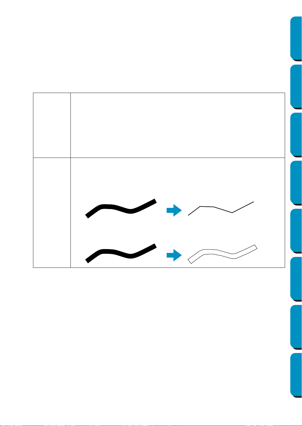
111
Contents Before Using Getting Started Design Center Layout & Editing
Programmable
Stitch Creator
Quick Reference Alphabetic Index
◆ If necessary, click Pick Area. A cross-shaped cur-
sor will appear. Select the desired area by moving
the cursor across the image. You will return to this
screen as soon as you release the mouse.
• The preview window reflects the setting
changes you make.
◆ Click
OK to confirm.
◆ Click Cancel to exit.
Resolution
This setting determines how detailed the generated pattern image will be. Basically,
the outline of the line image is converted into pieces of broken lines. To make a more
detailed pattern, you need more points on the broken lines, which also increases the
length of the file.
In general, Normal provides a sufficient resolution without making the file too large.
If Coarse gives a satisfactory result for a particular image, select Coarse in order to
keep the file as small as possible.
Select Fine only if the image contains many small details, and Normal does not give
a satisfactory result.
Thinning
Process
This setting determines how the black lines of the line image are converted into pat-
tern lines.
ON: the black lines are replaced with pattern lines following the center of the black
lines. You can set the degree of detailedness with the slider (if the degree is high,
even very thick black lines will be replaced with a center line).
OFF: the black lines are replaced with pattern lines following the border of the black
lines.
ON
OFF
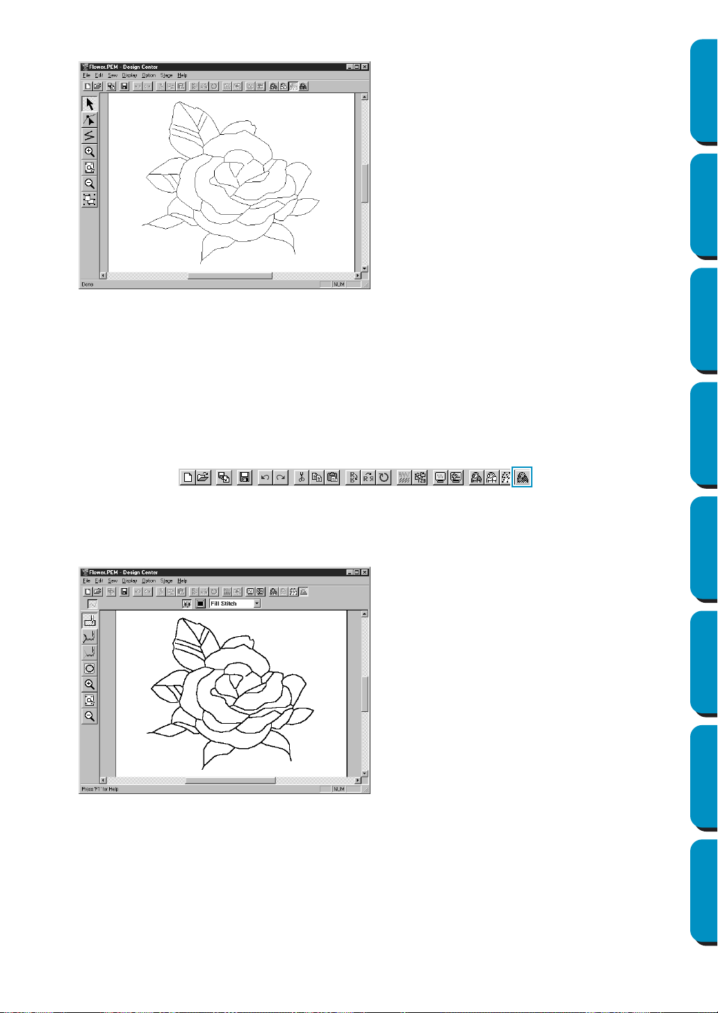
112
Contents Before Using Getting Started Design Center Layout & Editing
Programmable
Stitch Creator
Quick Reference Alphabetic Index
2 When you click OK, the Figure Handle Image displays and you are in Stage 3.
In Stage 3, you can edit the patterns, by moving, deleting and inserting points and by drawing
lines. Use the zooming tools available whenever you need to zoom your pattern.
See also: “To Original Image” and “To Line Image” on page 108, “To Sew Setting” below,
“Grid Setup” on page 103 and “Design Page Property” on page 106
■ To Sew Setting
Purpose: Moves from Stage 3 to Stage 4.
Shortcut key: No shortcut key for this function
Toolbar:
Operation:
1 Click Stage, then To Sew Setting.
You are now in Stage 4.
You can set the sewing attributes. Use the zooming tools available whenever you need to scale your pattern.
See also: “To Original Image” and “To Line Image” on page 108 and “To Figure Handle” on
page 110
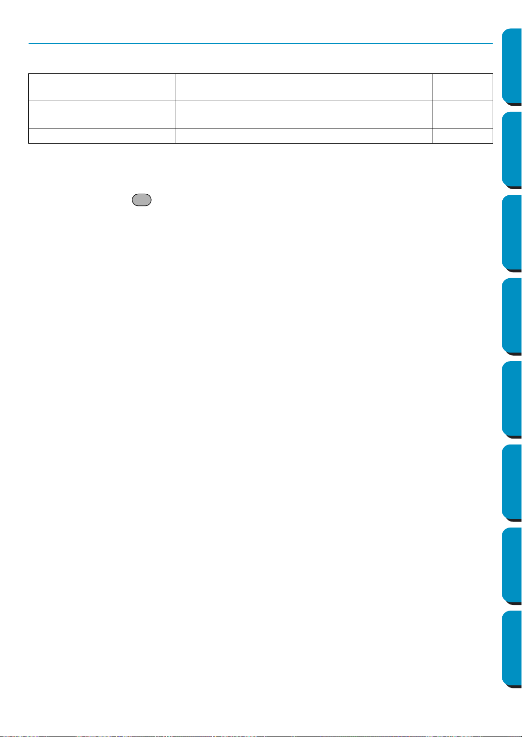
113
Contents Before Using Getting Started Design Center Layout & Editing
Programmable
Stitch Creator
Quick Reference Alphabetic Index
Help Menu
The Help menu gives you access to the on-screen help information system.
■ Contents
Purpose: Starts the on-screen help information for this application.
Shortcut key:
Toolbar: No button for this function
Operation:
1 Click Help, then Contents.
A table of contents of the on-screen help information displays.
2 Refer to your Windows manual for the next operation.
See also: “About Design Center” below
■ Customer support
Purpose: Opens the FAQ (Frequently Asked Questions) page in this company’s Web site.
Shortcut key: No shortcut key for this function
Toolbar: No button for this function
Operation:
1 Click Help, then Customer support from the menu.
2 The browser installed in the computer will start, and open the FAQ page of this company’s Web
site.
NOTE:
This function cannot be used if there is no Internet browser correctly installed in the computer.
■ About Design Center
Purpose: Gives information about the version of this application.
Shortcut key: No shortcut key for this function
Toolbar: No button for this function
Operation:
1 Click Help, then About Design Center.
A dialog will display.
2 Click OK to remove it.
See also: “Contents” above
Contents
Starts the on-screen help information for this applica-
tion.
page 113
Customer Support
Opens the FAQ (Frequently Asked Questions) page in
this company’s Web site.
page 113
About Design Center Gives information about the version of this application. page 113
F1

114
Contents Before Using Getting Started Design Center Layout & Editing
Programmable
Stitch Creator
Quick Reference Alphabetic Index
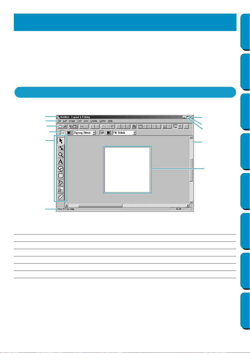
115
Contents Before Using Getting Started Design Center Layout & Editing
Programmable
Stitch Creator
Quick Reference Alphabetic Index
Layout & Editing is used to assemble an embroidery Design Page from different elements.
The most complex elements are created with Design Center and imported in the Design Page. You can
then add text, boxes, circles, broken lines, curves and manual punching patterns. You can move all the
patterns to obtain the best layout, and define sewing attributes (thread color and stitch type, including a
stitch pattern created by Programmable Stitch Creator) for the different components of your Design
Page.
When you have finished, you can save your work on your hard disk, print it, and transfer it to a card.
The card can be inserted in your sewing machine to automatically embroider your creation.
Menu bar Gives access to the functions.
Toolbar Shortcut for the menu functions.
Sewing attribute bar Sets the sewing attributes (color, stitch) of the patterns.
Tool box Used to select and create patterns.
Status bar Provides short information.
Design Page The actual part of the work area that can be saved and sewn.
Layout & Editing
The Screen
Menu bar
Toolbar
Sewing attributes
Tool box
Work area
Design Page
Status bar
Maximize button
Minimize button
Close button
Title bar
bar
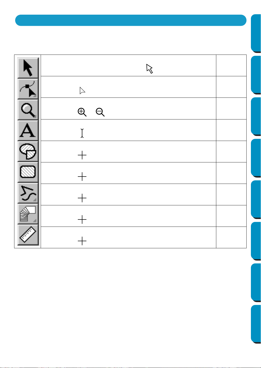
116
Contents Before Using Getting Started Design Center Layout & Editing
Programmable
Stitch Creator
Quick Reference Alphabetic Index
Patterns are created and edited using the Tool Box and the Sewing Attributes bar.
Clicking a button of the Tool Box changes the cursor mode and shape. The left side of the Status bar tells
you what you can do in each cursor mode.
Sets the cursor in selection mode. When you start the application, the selec-
tion mode is active by default. Cursor shape:
page 117
Sets the cursor in point edit mode.
Cursor shape:
page 120
Sets the cursor in zoom mode.
Cursor shape: or
page 125
Sets the cursor in text input mode.
Cursor shape:
page 127
Sets the cursor in circle and arc drawing mode.
Cursor shape: with a miniature of the tool button
page 129
Sets the cursor in rectangle drawing mode.
Cursor shape: with a miniature of the tool button
page 131
Sets the cursor in outline drawing mode.
Cursor shape: with a miniature of the tool button
page 132
Sets the cursor in manual punching mode.
Cursor shape: with a miniature of the tool button
page 133
Sets the cursor in measure mode.
Cursor shape: with a miniature of the tool button
page 135
Using the Tool Box
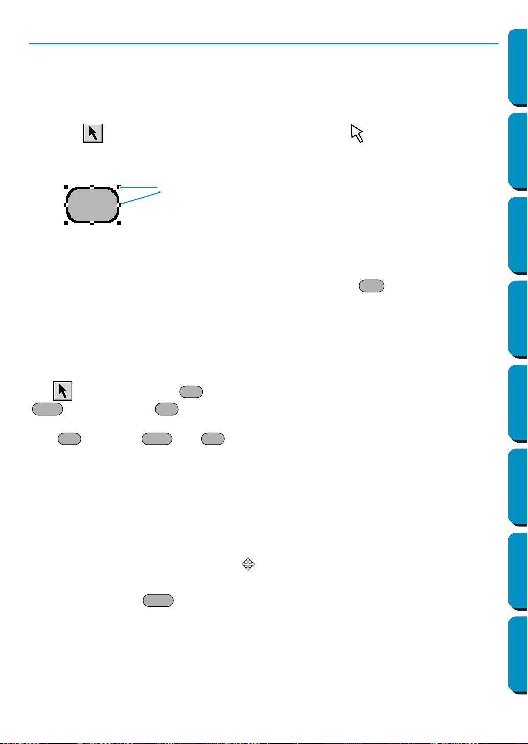
117
Contents Before Using Getting Started Design Center Layout & Editing
Programmable
Stitch Creator
Quick Reference Alphabetic Index
Selection Mode
To apply settings to an existing pattern, you must first select it.The cursor selection mode is used to
select one or more patterns. Once a pattern is selected, you can move it, scale it, and change its direc-
tion by rotating it or inverting it.
■ Selecting patterns
1
Click on the Tool Box. The shape of the cursor changes to .
2 Click the pattern that you want to select.
You know that the object is selected when handles are displayed.
The Status bar shows the dimensions (width and height) of the selection.
3 To deselect the pattern, select another one, click on the white space or click another tool button of
the Tool Box.
4 To select an additional pattern, click that pattern while holding the key down.
Note that you can also select patterns by dragging the cursor across the Design Page. As you
drag, a dotted rectangle appears. When you release the mouse button, all patterns that overlap
that rectangle will be selected.
If you select other patterns than you wanted to, click on the white space to deselect all, and start
again.
■ Selecting patterns 2
With is selected, press the key to select the next object in the sewing order. Hold down the
key and press the key to select the previous object in the sewing order.
If the key (or the and keys) are pressed:
• and no object is selected, the first object (or the last object) in the sewing order becomes selected.
• and multiple objects are selected, all objects become deselected except the soonest (or latest) object
within the sewing order.
• and the last (or first) object in the sewing order is selected, the first (or last) object in the sewing order
becomes selected.
■ Moving patterns
1
Move the cursor over a selected pattern or group of selected patterns.
The shape of the cursor will change to .
2 You can now drag the pattern to another location.
Holding down the key while dragging the pattern moves the pattern horizontally or verti-
cally.
NOTE:
By pressing the arrow keys, the selected pattern can be moved 0.5 mm (about 0.02 inch) to the
left, right, up or down.
• If Snap to Grid is selected, each press of an arrow key moves the pattern 1 grid mark in the
specified direction.
Handles
Ctrl
Tab
Shift Tab
Tab Shift Tab
Shift
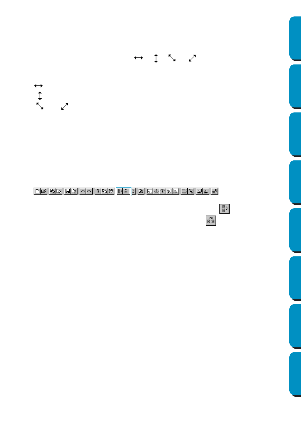
118
Contents Before Using Getting Started Design Center Layout & Editing
Programmable
Stitch Creator
Quick Reference Alphabetic Index
• The arrow keys cannot be used to move text on a path if just the text is selected. The path must
also be selected in order to move using the arrow keys.
■ Scaling patterns
1
Move the cursor over one of the handles of a selected pattern or group of selected patterns.
The shape of the cursor will change to , , or , depending on the handle the
cursor is on.
2 Drag the handle in the direction of the arrow to scale the pattern.
is for scaling the width.
is for scaling the height.
and are for scaling both dimensions at the same time.
As you drag the handle, you can check the changing size on the Status bar.
Note that some patterns imported from cards cannot be scaled.
When you scale imported patterns, the number of stitches remain the same, resulting in a quality
loss. To maintain the quality of the embroidery, you need to adjust the number of stitches after
scaling the pattern. This can be done in the Stitch to Block Sensitivity dialog, which you open by
selecting the Sew – Stitch to Block command. For more information on how to select this function,
see “Stitch to Block” on page 213.
■ Flipping a pattern horizontally or vertically
1
Select the data that you wish to flip horizontally or vertically. The buttons below become active.
2 To flip horizontally, select the command Edit – Mirror – Horizontal or click on the Toolbar.
To flip vertically, select the command Edit – Mirror – Vertical or click on the Toolbar.
NOTE:
Images imported from embroidery cards cannot be flipped if they were designed with the mirror
function turned off.
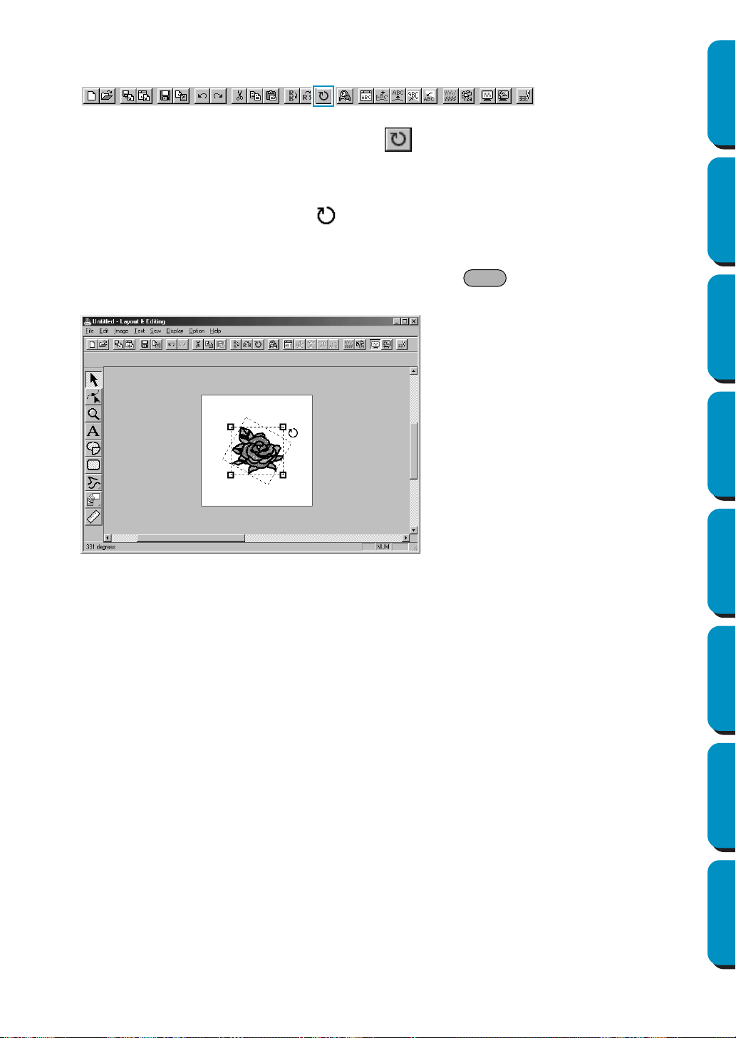
119
Contents Before Using Getting Started Design Center Layout & Editing
Programmable
Stitch Creator
Quick Reference Alphabetic Index
■ Rotating a pattern
1
Select the data that you wish to rotate.The button below becomes active.
2 Select the menu command Edit – Rotate or click on the Toolbar. The handles around the
selected pattern are replaced by smaller boxes on the four corners of the selected area.
3 To rotate the pattern, move the cursor on one of the four rotation handles.
The shape of the cursor changes to as soon as your cursor touches a rotation handle. Click
on a rotation handle and a lined box appears around the selected the pattern.
Rotate the pattern clockwise or counterclockwise by dragging the mouse. A simple dragging of the
mouse will rotate the pattern by 1˚ increments. Pressing the key will rotate it by 15˚ incre-
ments.
Shift
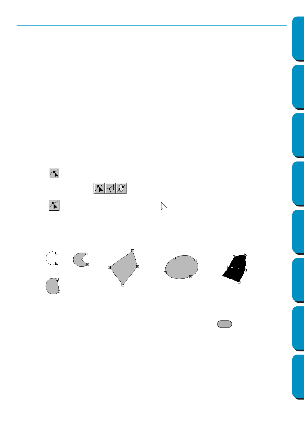
120
Contents Before Using Getting Started Design Center Layout & Editing
Programmable
Stitch Creator
Quick Reference Alphabetic Index
Point Edit Mode
The point edit mode is used to:
◆ move a point of a broken line, a curve, an arc, fan shape and arc & string or of a manual punching pat-
tern;
◆ reorient the tangent to a point of a curve;
◆ insert a new point in a broken line, curve or manual punching pattern;
◆ delete a point in a broken line, curve or manual punching pattern;
◆ realign the part of a broken line or a curve on both sides of a point;
◆ select and set a character in a text pattern.
◆ move, insert or delete stitch data of a stitch object
◆ edit the entry points and exit points of stitching for a shape object
■ Moving points
1
Click on the Tool Box.
Three buttons appear: .
2 Click . The shape of the cursor changes to .
3 Click the pattern that you want to edit.
The pattern can be a broken line, a curve, an arc, a fan shape, an arc & string or a manual punch-
ing pattern.
The existing points of the pattern are marked with small empty squares
4 Click the point that you want to move.
The selected point is marked with a small black square.
You can select more than one point by clicking them while holding the key down, or by
dragging the mouse across the area.
NOTE:
If you click on the line of the pattern instead of a square, a new point is inserted.
5 Drag the point to a new position.
All the selected points move in the same direction if more than one is selected.
The point remains selected, so that you can drag it again.
Ctrl

121
Contents Before Using Getting Started Design Center Layout & Editing
Programmable
Stitch Creator
Quick Reference Alphabetic Index
Holding down the key while dragging the point moves the point horizontally or vertically.
Note that you must drag a point that is selected. If you start dragging by clicking elsewhere on the
outline, a new point will be inserted or the selected point(s) will be deselected.
NOTE:
By pressing the arrow keys, the selected point can be moved 0.5 mm (about 0.02 inch) to the left,
right, up or down.
• If
Snap to Grid is selected, each press of an arrow key moves the point 1 grid mark in the spec-
ified direction.
• The arrow keys cannot be used to move the endpoints of an arc or text on a path if just the text
is selected.
■ Reorienting a tangent to a point
1
Click on the Tool Box.
Three buttons appear: .
2 Click . The shape of the cursor changes to .
3 Click the pattern that you want to edit.
The pattern can only be a curve.
The existing points of the pattern are marked with small empty squares.
4 Click the point at which you want to reorient the tangent to the curve.
The selected point is marked with a small black square and a control handle.
5 Click on one end of the handle and drag it without releasing the mouse.
■ Inserting points
1
Click on the Tool Box.
Three buttons appear: .
2 Click . The shape of the cursor changes to .
Shift
4
5
45 4
Handle
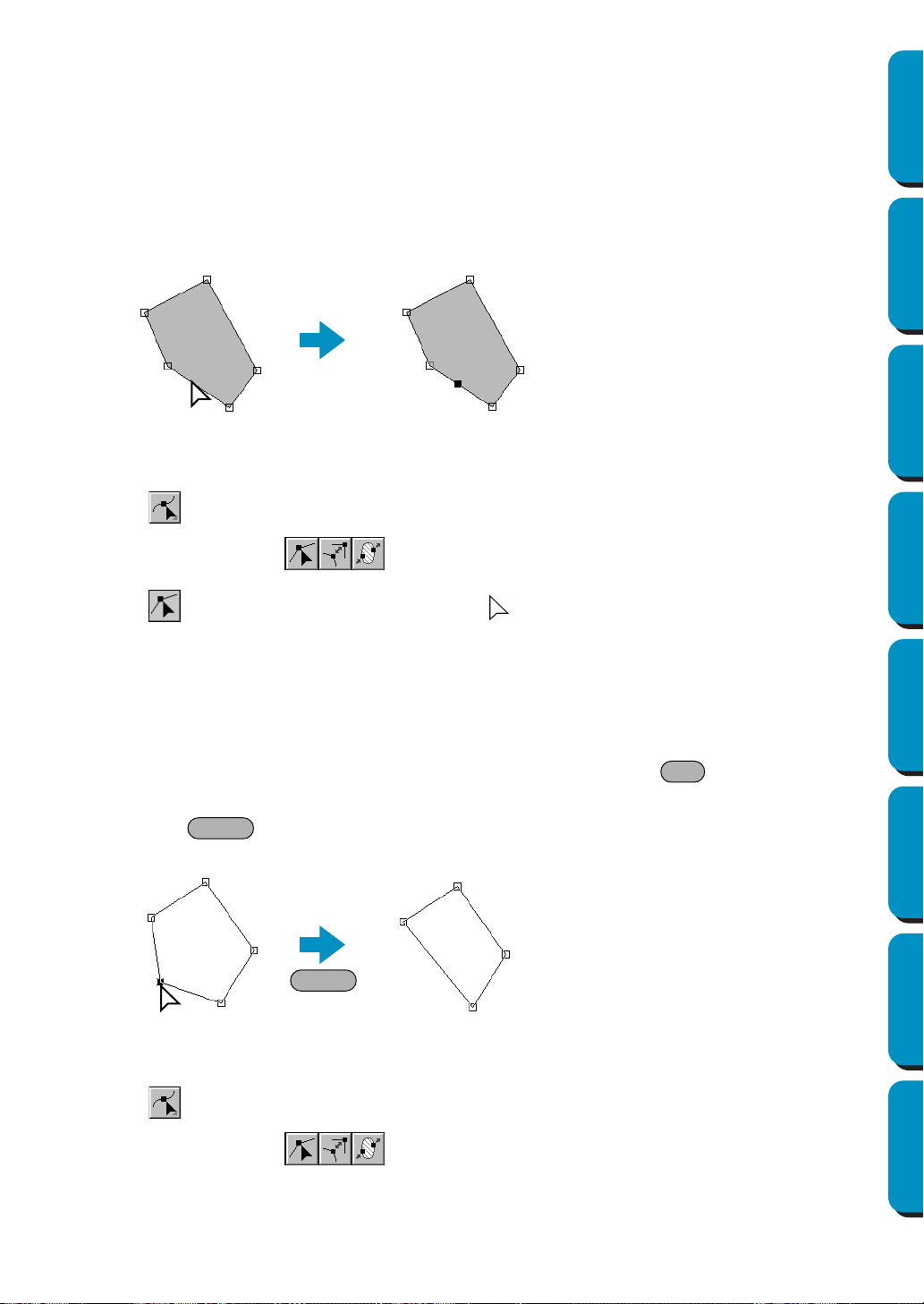
122
Contents Before Using Getting Started Design Center Layout & Editing
Programmable
Stitch Creator
Quick Reference Alphabetic Index
3 Click the pattern that you want to edit.
The pattern can be a broken line, a curve or a manual punching pattern.
The existing points of the pattern are marked with small empty squares.
4 Click at a point of the contour other than an existing point.
A new point appears and is automatically selected (marked with a small black square and in the
case of a curve, with a control handle).
When a manual punching pattern is selected, a pair of new points is inserted.
The new point can be immediately moved. In the case of a new point on a curve, you can also use
the handle to reorient the tangent to the new point.
■ Deleting points
1
Click on the Tool Box.
Three buttons appear: .
2 Click . The shape of the cursor changes to .
3 Click the pattern that you want to edit.
The pattern can be a broken line, a curve or a manual punching pattern.
The existing points of the pattern are marked with small empty squares.
4 Click the point that you want to delete.
The selected point is now marked with a small black square.
You can select more than one point by clicking them while holding the key down, or by
dragging the mouse across the area.
5 Press the key to remove the point from the path. When a manual punching pattern is
selected, a pair of points is deleted.
■ Realigning
1
Click on the Tool Box.
Three buttons appear: .
4
Ctrl
Delete
Delete
4
5

123
Contents Before Using Getting Started Design Center Layout & Editing
Programmable
Stitch Creator
Quick Reference Alphabetic Index
2 Click . The shape of the cursor changes to and displays together with a small image of
the Tool Box button.
3 Click the pattern that you want to edit.
The pattern can be a broken line or a curve.
The existing points of the pattern are marked with small empty squares.
4 Click the point that you want to realign.
If the point was on a curved part, it is now on a broken line and vice versa.
NOTE:
When the point is on a curved part, you can use the handle to reorient the tangent (see “Reorient-
ing a tangent to a point” on page 121).
■ Selecting characters on a text pattern
1 Click on the Tool Box.
Three buttons appear: .
2 Click . The shape of the cursor changes to .
3 Click the text pattern that you want to edit.
The existing points of the text are marked with small empty squares.
4 Click the square of the character that you want to select.
If you want to select more than one character, hold the key while clicking other squares or
drag the cursor across.
The selected characters are marked with black squares.
5 When some characters of a text pattern are selected, you can apply a font, size, color, stitch and
other attributes different from the rest of the text pattern.
■ Editing stitch data of a stitch object
1
Click on the Tool Box.
Three buttons appear: .
2 Click . The shape of the cursor changes to .
Ctrl
3
4
5

124
Contents Before Using Getting Started Design Center Layout & Editing
Programmable
Stitch Creator
Quick Reference Alphabetic Index
3 Click the stitch object that you want to edit.
The existing stitch data in the stitch object are marked with small empty squares.
NOTE:
Stitch objects are patterns surrounded with a dotted line.
If the shape object is not surrounded with a dotted line, it cannot be edited. Select the menu com-
mand
Sew – Convert to Stitch to convert the pattern to a stitch object.
4 Selecting stitch points
Click the points that you want to select, or drag the cursor across them.
The selected points are marked with black squares.
Other selection methods
• Select more points by holding down the key while clicking the additional points or by
dragging the cursor across the area.
• If the key is held down while another point is clicked, all points between the two selected
points (within the stitching order) are selected.
• Hold down the key and press the → or ↓ key to select additional points in the sewing
direction from the current point, or hold down the key and press the ← or ↑ key to select
additional points in the opposite direction of sewing from the current point.
• Hold down the key and press the → or ↓ key to move the selection in the sewing direc-
tion, or hold down the key and press the ← or ↑ key to move the selection in the opposite
direction of sewing.
• Press the key to select all points in the next color. Hold down the key and press
the key to select all points in the previous color.
Moving stitch points
The selected points can be dragged to the new position.
If the key is held down while the points are dragged, the selection can only be moved hor-
izontally or vertically.
If the ←, ↑, ↓ or → key is pressed, the selection is moved in the corresponding direction by 0.1
mm.
Inserting stitch points
Click on a line between two points to add a new point at that position.
Deleting stitch points
Press the key to delete the selected point.
■ Editing entry/exit points of a shape object
1
Click on the Tool Box.
Three buttons appear: .
2 Click . The shape of the cursor changes to and displays together with a small image of
the Tool Box button.
NOTE:
If a check mark appears in front of the
Optimize Entry/Exit points setting on the Sew menu (the set-
ting is turned on), this button cannot be selected. To use this tool to manually edit the entry and
exit points, turn off the Optimize Entry/Exit points setting.
Ctrl
Shift
Shift
Shift
Ctrl
Ctrl
Tab Shift
Tab
Shift
Delete
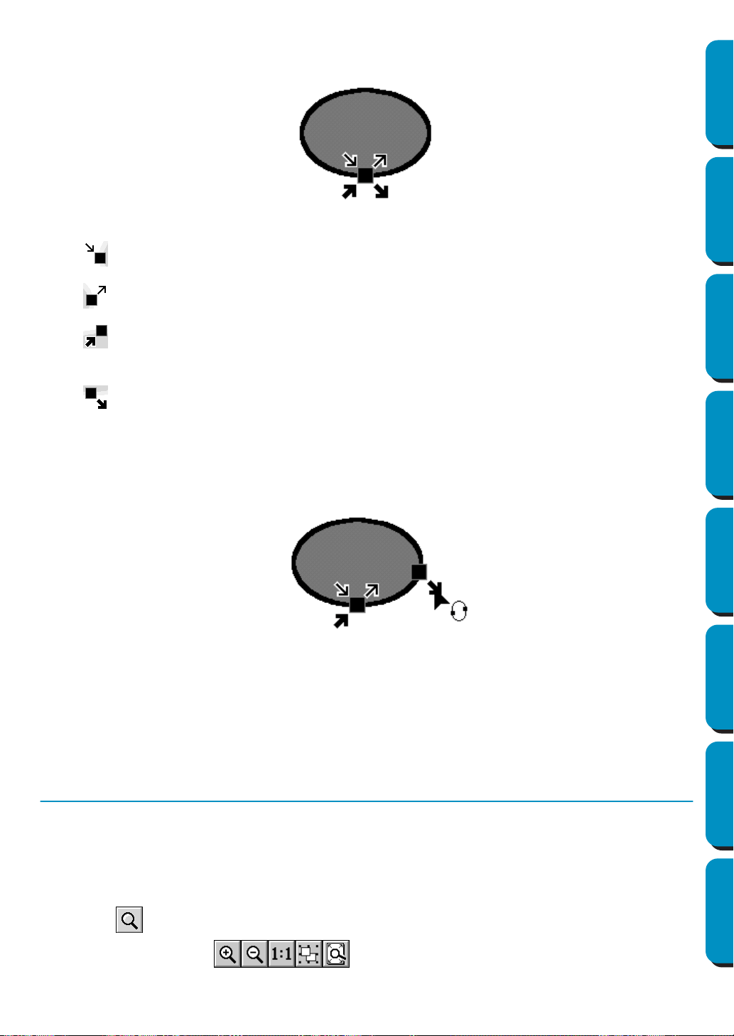
125
Contents Before Using Getting Started Design Center Layout & Editing
Programmable
Stitch Creator
Quick Reference Alphabetic Index
3 Click the shape object that you want to edit.
The entry points and the exit points of the shape object appear as shown below.
The symbols representing the four overlapping points shown above are described below:
: This is the entry point for sewing the outlines. The previous pattern is connected to this point.
:
This is the exit point for sewing the outlines. From this point, sewing continues to the next pattern.
: This is the entry point for sewing the inside regions. The previous pattern is connected to this
point.
: This is the exit point for sewing the inside regions. From this point, sewing continues to the
next pattern.
If the outlines or the inside regions are not set to be sewn, the corresponding point does not appear.
4 Drag the arrow mark for the point that you want to edit along the outline to the desired position.
Continue this step until all points are moved to the desired positions.
NOTE:
• Shape objects that can be edited in this way are data created with the Circle, Rectangle and Out-
line tools. Objects created with the Text or Manual punch tools cannot be edited.
• If the Optimize Entry/Exit points setting on the Sew menu is turned on, all manual adjustments of
the entry points and exit points will be lost, and the points will be automatically optimized.
Zoom Mode
The zoom mode is used to control the scale of the display. You can zoom in to work on details of a pattern
with higher precision and you can zoom out again to see and work on parts of your Design Page that is
hidden.
■ Zooming in
1
Click .
Five buttons appear: .
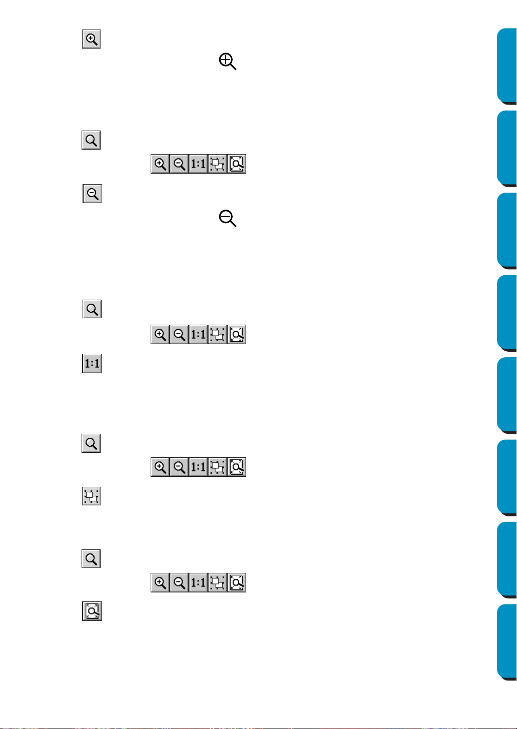
126
Contents Before Using Getting Started Design Center Layout & Editing
Programmable
Stitch Creator
Quick Reference Alphabetic Index
2 Click .
The shape of the cursor changes to .
3 Drag the cursor across the area that you want to enlarge.
The area is enlarged as soon as you release the mouse. You can repeat the entire operation.
■ Zooming out
1
Click .
Five buttons appear: .
2 Click .
The shape of the cursor changes to .
3 Click a point of the Design Page where you want to do the next work.
The image shrinks toward that point.
You can repeat this step until the image has returned to its normal size.
■ Zooming to the real size
1
Click .
Five buttons appear: .
2 Click .
Your Design Page now appears in (almost) real size.
■ Enlarging selected objects to the screen size
1
Select one or more patterns.
2 Click .
Five buttons appear: .
3 Click .
The selected objects now occupy all the available space on the screen.
■ Return to the standard scale
1
Click .
Five buttons appear: .
2 Click .
The Design Page is zoomed in or out to return to the standard scale.
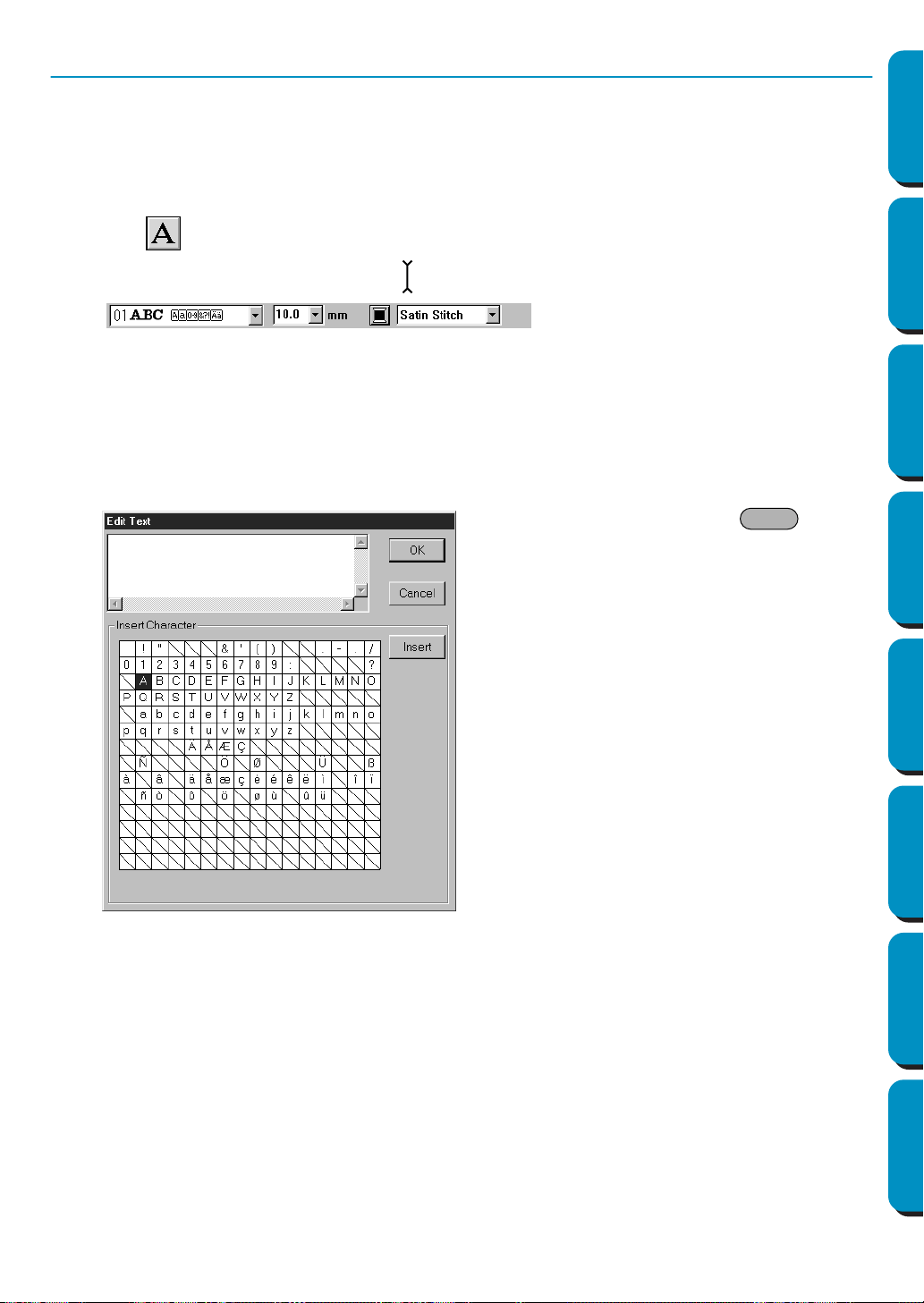
127
Contents Before Using Getting Started Design Center Layout & Editing
Programmable
Stitch Creator
Quick Reference Alphabetic Index
Text Input Mode
The text input mode is used to enter strings of text in your Design Page. You can enter accented charac-
ters for European languages, that are not directly available on your keyboard.
The basic settings for the text strings include font and size.
■ Entering text
1
Click on the Tool Box.
The shape of the cursor changes to . The Sewing Attributes bar now looks like this:
You can select a color, a font and a size at this step or after creating the pattern.
See “Color” on page 144, “Font” on page 138 and “Text size” on page 140.
You can also set the sewing attributes using the Sew menu (see “Sewing Attribute Setting” on
page 204) and the text attributes using the Text menu (see “Text Attribute Setting” on page 198).
2 Click at a point where you want the text to appear.
The Edit Text dialog displays.
◆ Type your text. Press the key to
enter new lines of text.
◆ You can also enter a character by clicking
it on the character table, then clicking
Insert or simply by double-clicking it. This
is specially useful if you have to enter
accented characters that are not avail-
able on your keyboard.
◆ Click OK to confirm. Your text opens on
the Design Page.
◆ Click Cancel to exit.
• If a character that you entered is not
available for the selected font, a warning
message displays. Click
OK in that dialog
to close it and to return to the Edit Text
dialog where you can correct your text.
Enter
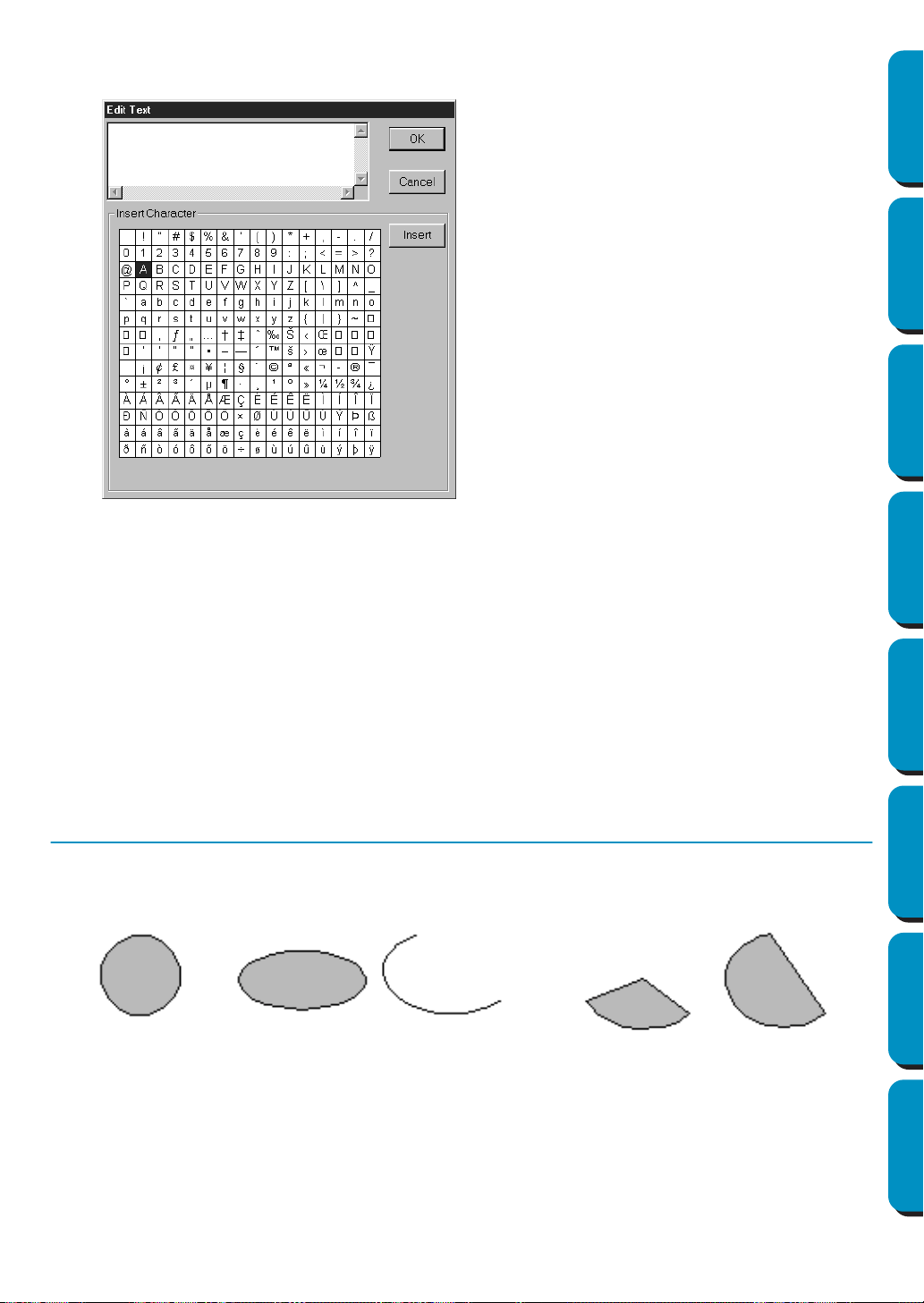
128
Contents Before Using Getting Started Design Center Layout & Editing
Programmable
Stitch Creator
Quick Reference Alphabetic Index
(If a TrueType Font is selected)
If a TrueType Font is selected, a dialog similar to the one shown below will appear.
Based on the set attributes, all characters for the selected font appear in the Insert Character chart.
Enter characters in the same way that you would enter characters with a built-in font (as explained
above).
NOTE:
With some TrueType fonts, the text cannot be converted correctly into embroidery data due to the
shape of the design or the text cannot be embroidered correctly. Before sewing your project,
embroider a trial piece of fabric. In addition, text of some TrueType fonts cannot be converted. In
this case, the area containing the converted text will be empty or a message warning that the text
cannot be converted will appear.
NOTE:
If you need to edit the entered text, you can do so in the Edit Text dialog which opens when you
execute the Text – Edit Text Letters command. See “Edit Text Letters” on page 197.
Circle and Arc Drawing Mode
The circle or arc drawing mode allows you to create several patterns related to the circle: normal circles
(or ellipses), arcs, fan shapes and arc & strings.
All these patterns, except arcs have an outline and a region inside can independently be assigned differ-
ent sewing attributes. Arcs are simple outlines.
Note that you have to decide which pattern type you want to draw before drawing it. You cannot, for
example, draw a normal circle and change it into an arc afterwards.
Circle Ellipse Arc Fan shape Arc & string
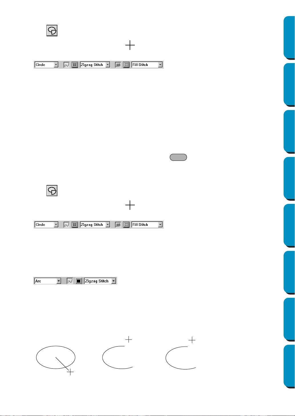
129
Contents Before Using Getting Started Design Center Layout & Editing
Programmable
Stitch Creator
Quick Reference Alphabetic Index
■ Drawing a circle or an ellipse
1
Click on the Tool Box.
The shape of the cursor changes to and displays together with a small ellipse. The Sewing
Attributes bar now looks like this:
You can select the colors and stitches at this step or after creating the pattern. See “Color” on
page 144 and “Stitch” on page 146.
You can also set the sewing attributes using the Sew menu (see “Sewing Attribute Setting” on
page 204).
You must decide now which kind of circle-related graphic you need.
2 Click the Arc shape selector, then click Circle.
3 Move the mouse to a point, click and drag the mouse.
The point where you start dragging is considered a corner of an imaginary rectangle. The point
where you release the mouse will be the diagonally opposed point of the rectangle. The ellipse will
fit inside the imaginary rectangle (its great axis equal to the larger edge of the rectangle, and it
small axis equal to the smaller edge).
Note that you can draw a perfect circle by holding the key down while dragging the
mouse.
■ Drawing an arc
1
Click on the Tool Box.
The shape of the cursor changes to and displays together with a small ellipse. The Sewing
Attributes bar now looks like this:
You can select the colors and stitches at this step or after creating the pattern. See “Color” on
page 144 and “Stitch” on page 146.
You can also set the sewing attributes using the
Sew menu (see “Sewing Attribute Setting” on
page 204).
You must decide now which kind of circle-related graphic you need.
2 Click the Arc shape selector, then click Arc.
3 Proceed as you would to draw a circle or an ellipse.
When you release the mouse, a radial line appears on the ellipse.
4 Move the cursor (without dragging) to the start point of the arc and click.
The radial line disappears.
5 Move the cursor (without dragging) to the end point of the arc and click.
Shift
Click at start point
Move to end point
Click at end point
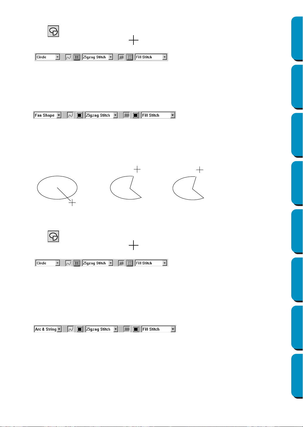
130
Contents Before Using Getting Started Design Center Layout & Editing
Programmable
Stitch Creator
Quick Reference Alphabetic Index
■ Drawing a fan shape
1
Click on the Tool Box.
The shape of the cursor changes to and displays together with a small ellipse. The Sewing
Attributes bar now looks like this:
You can select the colors and stitches at this step or after creating the pattern. See “Color” on
page 144 and “Stitch” on page 146.
You can also set the sewing attributes using the Sew menu (see “Sewing Attribute Setting” on
page 204). You must decide now which kind of circle-related graphic you need.
2 Click the Arc shape selector, then click Fan shape.
3 Proceed as you would to draw a circle or an ellipse.
When you release the mouse, a radial line appears on the ellipse.
4 Move the cursor (without dragging) to the start point of the fan shape and click.
The radial line disappears.
5 Move the cursor (without dragging) to the end point of the fan shape and click.
■ Drawing an arc & string
1
Click on the Tool Box.
The shape of the cursor changes to and displays together with a small ellipse. The Sewing
Attributes bar now looks like this:
You can select the colors and stitches at this step or after creating the pattern. See “Color” on
page 144 and “Stitch” on page 146.
You can also set the sewing attributes using the
Sew menu (see “Sewing Attribute Setting” on
page 204).
You must decide now which kind of circle-related graphic you need.
2 Click the Arc shape selector, then click Arc & String.
3 Proceed as you would to draw a circle or an ellipse.
When you release the mouse, a radial line appears on the ellipse.
4 Move the cursor (without dragging) to the start point of the arc & string and click.
The radial line disappears.
Click at start point
Move to end point
Click at end point
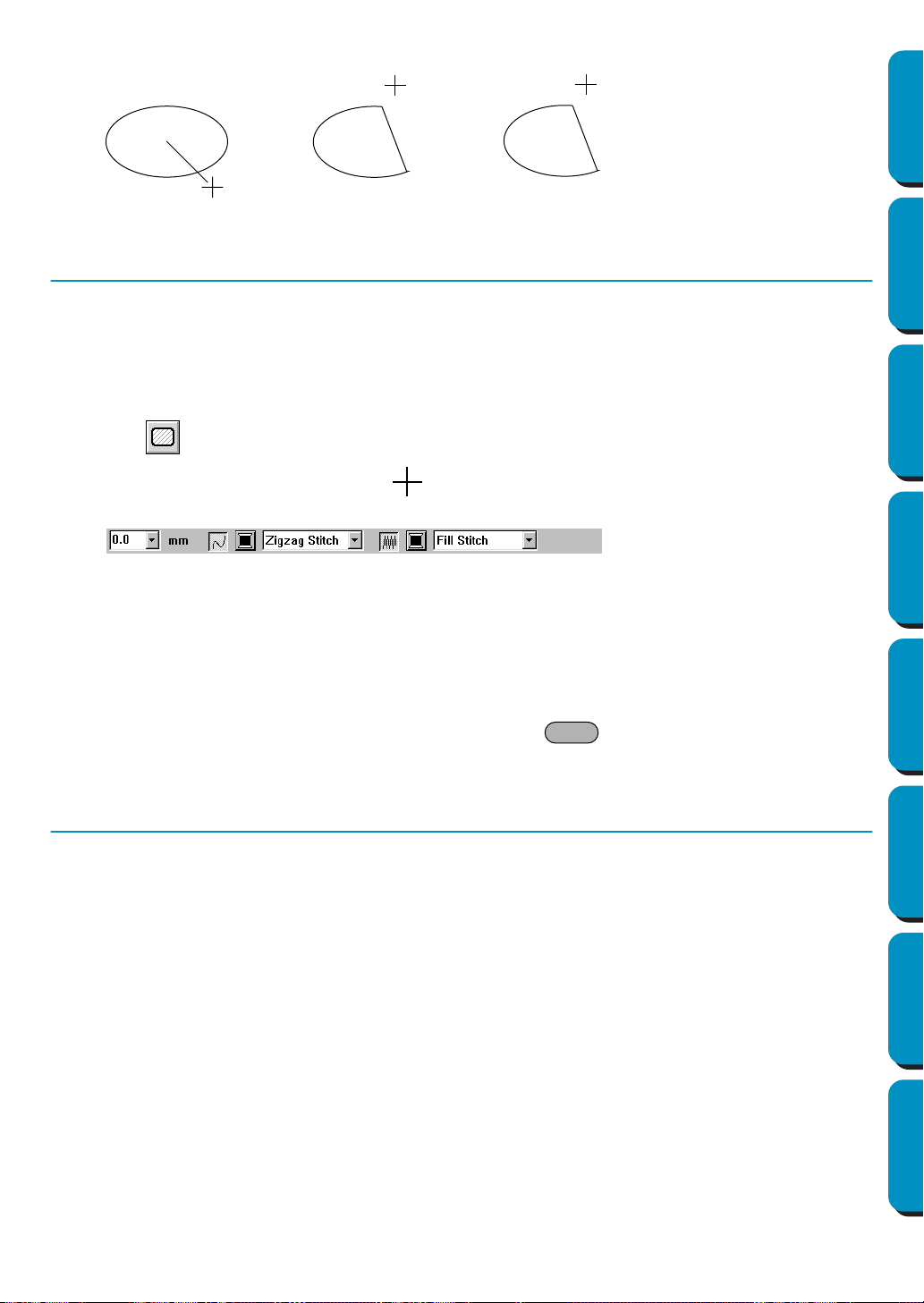
131
Contents Before Using Getting Started Design Center Layout & Editing
Programmable
Stitch Creator
Quick Reference Alphabetic Index
5 Move the cursor (without dragging) to the end point of the arc & string and click.
Rectangle Drawing Mode
With the rectangle drawing mode, you can create rectangles (boxes) with sharp or rounded corners. A
box will automatically have an outline and a region inside that can independently be assigned different
sewing attributes.
■ Drawing a box
1
Click on the Tool Box.
The shape of the cursor changes to and displays together with a small rounded box. The
Sewing Attributes bar now looks like this:
You can set the edge radius, colors and stitches at this step or after creating the pattern. See
“Edge radius” on page 137, “Color” on page 144 and “Stitch” on page 146.
You can also set the sewing attributes using the
Sew menu (see “Sewing Attribute Setting” on
page 204).
2 Move the mouse to a point, click and drag the mouse.
The point where you start dragging is considered a corner of the box. The point where you release
the mouse will be the diagonally opposed corner of the box.
Note that you can draw a perfect square by holding the key down while dragging the
mouse.
Outline Drawing Mode
The outline drawing mode allows you to add lines and curves to your pattern.
If the pattern is open, it will end at the last point entered. Since this type of pattern does not have an
inside region, it is considered a simple outline when setting the stitch and color.
If the pattern is closed, the last point will be automatically joined with the first one. Since this type of pat-
tern has an outline and an inside region, each part can be assigned different stitches and colors. How-
ever, if the line of the pattern crosses itself, the inside region cannot be determined.
While creating the pattern, you can freely switch between drawing straight lines or curves.
Furthermore, if an image is used as a template, there is a tool that automatically extracts the image
boundary.
Click at start point
Move to end point
Click at end point
Shift

132
Contents Before Using Getting Started Design Center Layout & Editing
Programmable
Stitch Creator
Quick Reference Alphabetic Index
■ Drawing a line
1
Click on the Tool Box.
Three buttons appear:
is for drawing straight lines. (Shortcut key: )
is for drawing curves. (Shortcut key: )
is for semi-automatically drawing lines. (Shortcut key: )
2 Click the button for the type of line that you want to draw. The shape of the cursor changes to
and displays together with the symbol for the selected line type. The Sewing Attributes bar now
looks like this:
You can select the path shape, colors and stitches at this step or after creating the pattern. See
“Path shape” on page 138, “Color” on page 144 and “Stitch” on page 146.
You can also set the sewing attributes using the
Sew menu (see “Sewing Attribute Setting” on
page 204).
3 Draw the outline.
Move the mouse to the start point and click.
Move the mouse to the end point of the first line and click again.
NOTE:
You can always remove the last-entered point by clicking the right mouse button.
4 Repeat until you arrive at the last end point. At that point double-click.
NOTE:
• While drawing the pattern, you can freely switch between the different line types either by clicking
a different button or by pressing the shortcut key.
• When drawing a straight line, hold down the key while moving the mouse to draw verti-
cally or horizontally.
• A template image is needed in order to draw using the semi-automatic line drawing tool. If there
is no image, this tool will draw like the normal straight line drawing tool.
Open line
Closed line
Start point
End point
This closed broken line has no region inside.
Open curve
Closed curve
Start point
End point
This closed curve has no region inside.
Z
X
C
Shift
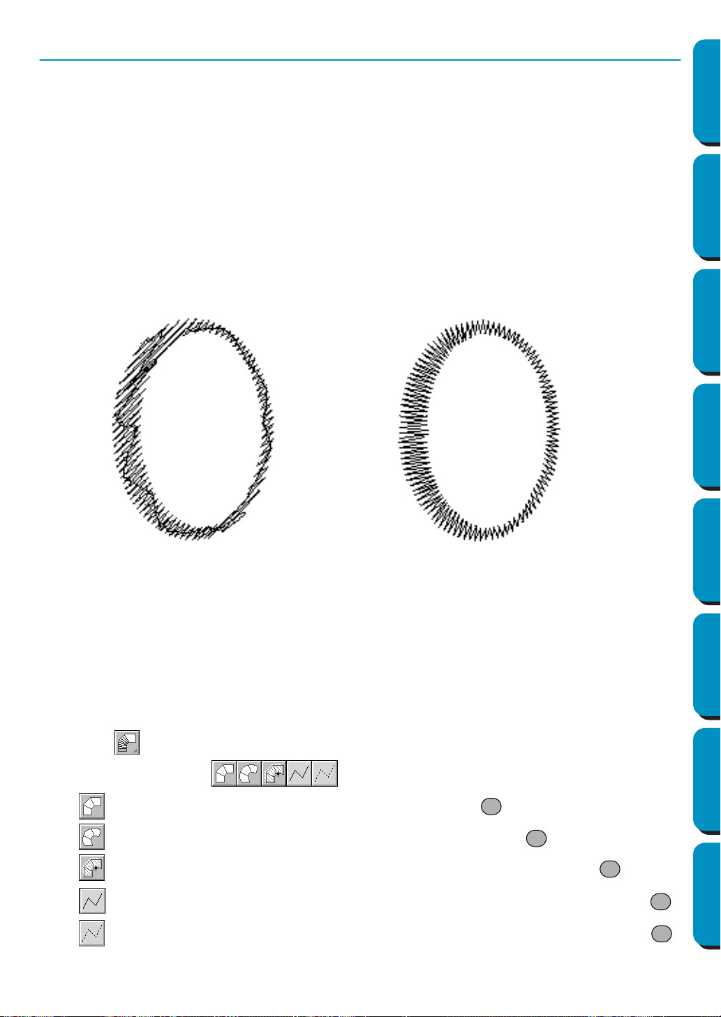
133
Contents Before Using Getting Started Design Center Layout & Editing
Programmable
Stitch Creator
Quick Reference Alphabetic Index
Manual Punching Mode
This mode is used to create patterns that look like manual embroidery. When you use the standard Fill or
Satin stitch to fill a region, the thread in the whole region has the same direction. Some patterns, how-
ever, look better when the thread direction “follows” the curves of the pattern. The Manual Punching
mode provides such a feature.
Letters that you design yourself constitute a typical example of patterns that look better when using the
Manual Punching mode. The illustrations below show the preview of two letters “O”.
The first one has been designed using two concentric ovals without a line sew setting, filling the larger
oval with Fill stitch and turning off the region sew setting inside the small oval. The pair was then set for
hole sewing.
The second letter has been redrawn using Manual Punching. To do this, we duplicated the first letter,
removed the region inside, and created a manual punching pattern using the outlines of the ovals as
guides. The ovals were then deleted.
The stitch density for both letters was set to a minimum in order to make it easier to see the difference
between the two patterns on the preview display.
When creating a manual punching pattern, it is easier to use something in the background as a guide. In
the above example, we used two ovals that we removed after completing the manual punching pattern.
Another possibility is to load a template image and redraw it using manual punching patterns. The advan-
tage of this method over the automatic conversion provided by Design Center is that you have a better
control on the thread orientation.
■ Creating a manual punching pattern
1
Open a template or prepare a pattern that you will use as a guide.
2 Click on the Tool Box.
Five buttons appear:
is for creating block-type punching patterns. (Shortcut key: )
is for creating curved block-type punching patterns. (Shortcut key: )
is for semi-automatically creating block-type punching patterns. (Shortcut key: )
is for creating running-type punching patterns (the broken line is sewn). (Shortcut key: )
is for creating feed-type punching patterns (the broken line is not sewn). (Shortcut key: )
Fill stitch
Manual Punching
(the thread has a constant direction)
(the direction of the thread follows the curve)
Z
X
C
V
B
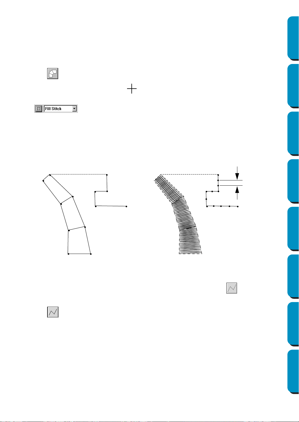
134
Contents Before Using Getting Started Design Center Layout & Editing
Programmable
Stitch Creator
Quick Reference Alphabetic Index
While creating a manual punching pattern, you can alternate the types. For example, you can start
with a block-type pattern, then switch to a running-type pattern (to draw an outline of the block-
type pattern) then switch to the feed type to move to the beginning of the next block-type pattern.
The whole pattern, consisting of different types, will be considered a single object (all parts will
have the same stitch and color).
In the example below, we start with a block-type pattern, use the feed type to move the cursor,
then create a run-type pattern.
3 Click to start creating a block-type pattern.
The shape of the cursor changes to and displays together with a small image of the block-
type button. The Sewing Attributes bar now looks like this:
You can select the color and stitch at this step or after creating the pattern. See “Color” on page
144 and “Stitch” on page 146.
You can also set the sewing attributes using the Sew menu (see “Sewing Attribute Setting” on
page 204).
4 Click point 1 on the Design Page (start point).
Click point 2 and next points referring to the illustration below.
Note that you can always click the mouse’s right button to remove the last entered point.
5 After clicking at point 8 (the last point of the above block-type pattern), click (feed-type pat-
tern button), then click at point 9 (the start point of the running-type pattern).
6 Click (running-type pattern button) and click at points 10, 11, and 12 shown in the above
illustration.
7 When you reach point 13, (the last point of the entire pattern), double click to complete the pattern.
NOTE:
• You can freely switch between the block-type and the curved block-type punching pattern by
using the Point Edit tool.
• When entering points, change the punch type by pressing the appropriate shortcut key.
• A template image is needed in order to use the semi-automatic block-type punch tool. If there is
no image, this tool will create a punching pattern like the normal block-type punch tool.
1
2
3
4
5
6
7
8
9
10
11
12
13
1
2
3
4
5
6
7
8
9
10
11
12
13
Step pitch
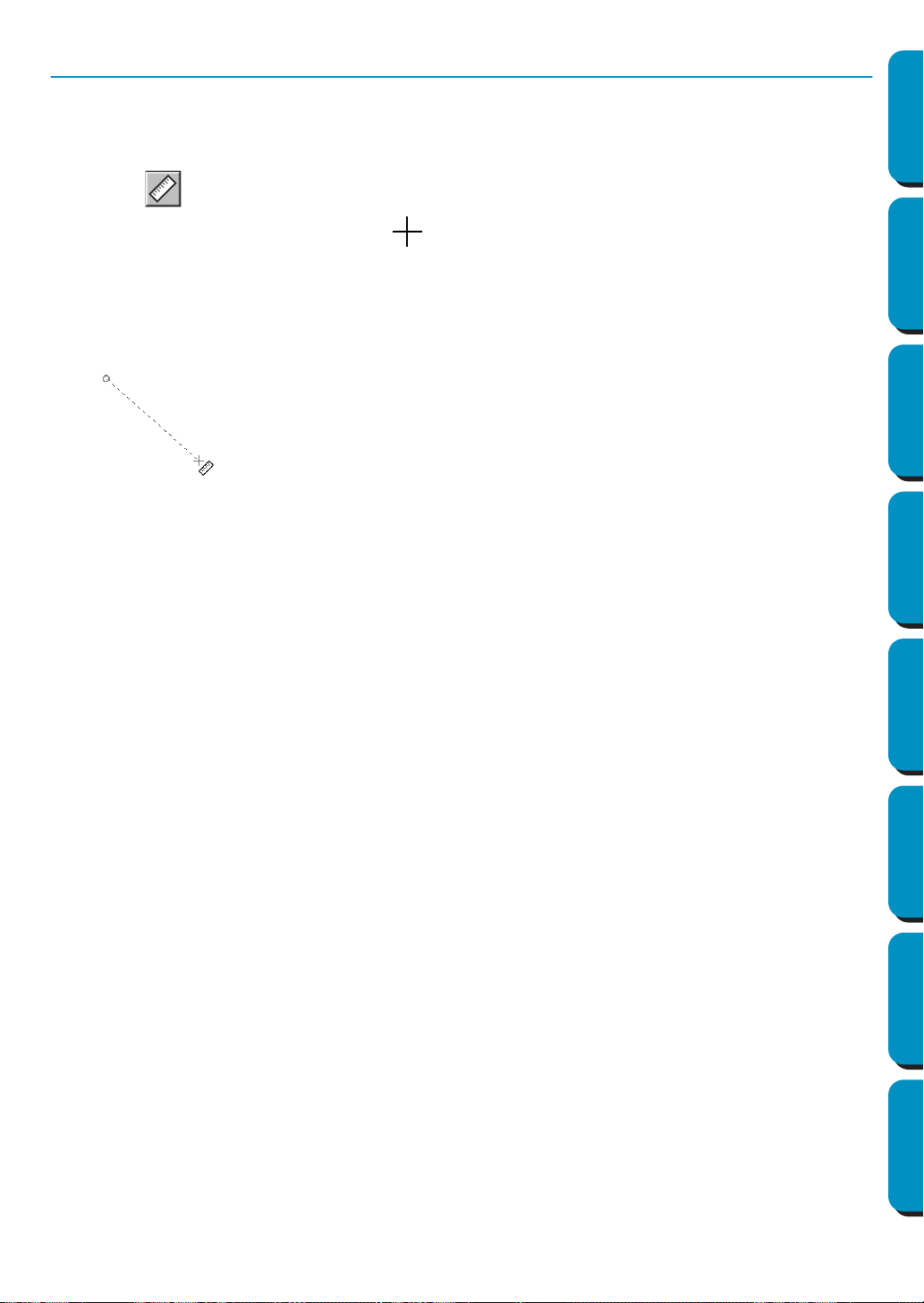
135
Contents Before Using Getting Started Design Center Layout & Editing
Programmable
Stitch Creator
Quick Reference Alphabetic Index
Measure Mode
The measure mode allows you to measure the distance between any two points.
■ Measuring the distance between two points
1
Click on the Tool Box.
The shape of the cursor changes to and displays together with a small ruler.
2 Click one end of the length that you want to measure. A small circle appears to indicate the start-
ing point of the distance.
Drag the cursor to view the length in the status bar between the starting point and the cursor’s
position.
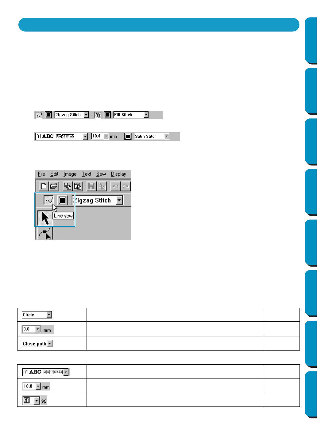
136
Contents Before Using Getting Started Design Center Layout & Editing
Programmable
Stitch Creator
Quick Reference Alphabetic Index
The Sewing Attributes bar allows you to set the following characteristics:
◆ geometric attributes (arc shape, rectangle edge radius, and path shape);
◆ text attributes (font, size and transformation level);
◆ embroidery attributes (thread color and stitch, outline and region inside on/off).
The sewing attributes which are available depend on the cursor mode and the type of embroidery pattern
selected.
Example 1: The cursor is in selection mode, but nothing is selected.
Example 2: The cursor is in text input mode, or in selection mode with text selected.
When the cursor is left for a while on an element of the Sewing Attributes bar, a label indicating the func-
tion of that element appears. In the following instructions, we will name the components of the Sewing
Attributes bar according to these labels, for easier identification.
As a general rule, the different characteristics available for a given pattern can be set either just before
creating the pattern, or after the pattern is created. For example, when drawing a rectangle, you can set
the colors and the corner radius just after starting the Rectangle Drawing mode. When the rectangle is
created, you can select it and change its characteristics.
The only exception to that rule is when you use the Circle and Arc Drawing mode: you must decide what
kind of pattern you want (circle, arc, etc.) before actually creating it. And you will not be able to change
that once the pattern is created.
Geometric attributes
Arc shape: Selects the type of arc. page 137
Edge radius: Sets the corners of rectangles. page 137
Path shape: Opens and closes broken lines and curves. page 138
Text attributes
Font: Selects a font for text. page 138
Text Size: Selects the size for text. page 140
Transform level: Selects the level of transformation. page 141
Using the Sewing Attributes Bar
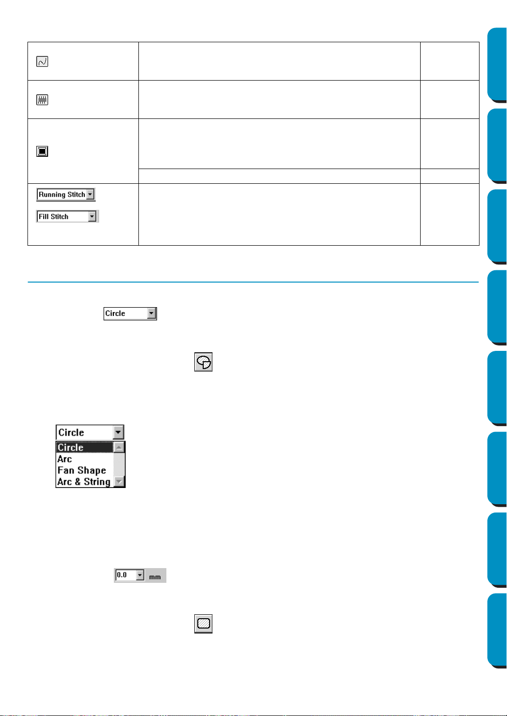
137
Contents Before Using Getting Started Design Center Layout & Editing
Programmable
Stitch Creator
Quick Reference Alphabetic Index
Setting Geometric Attributes
■ Arc shape
Purpose: Selects the type of arc.
Available: When you click on the Tool Box to start the Circle and Arc Drawing mode.
Operation:
1 Click the Arc shape selector.
The options display.
2 Click one of the options.
The setting applies to all the patterns that you will create in the Circle and Arc Drawing mode until
you change the setting.
See also: “Circle and Arc Drawing Mode” on page 128
■ Edge radius
Purpose: Sets the corners of rectangles.
Available: When you click on the Tool Box to start the Rectangle Drawing mode.
When you select an existing rectangle with the cursor in Selection mode.
Embroidery attributes
Line sew: Switches the outline on/off. When the outline is
switched off, it is not sewn (and you cannot set its color or
stitch).
page 142
Region sew: Switches the inside region on/off. When the
inside region is switched off, it is not sewn (and you cannot set
its color or stitch).
page 143
Line color, Region color, Text color, Punch color: Sets the
thread color for outline, region inside, text, manual punching
pattern and imported pattern (after the Stitch to Block function
has been applied).
page 144
Special colors page 145
Line sew type: Sets the stitch for the outlines.
Region sew type: Sets the stitch for outline, region inside, text,
manual punching pattern and imported pattern (after the Stitch
to Block function has been applied).
page 146
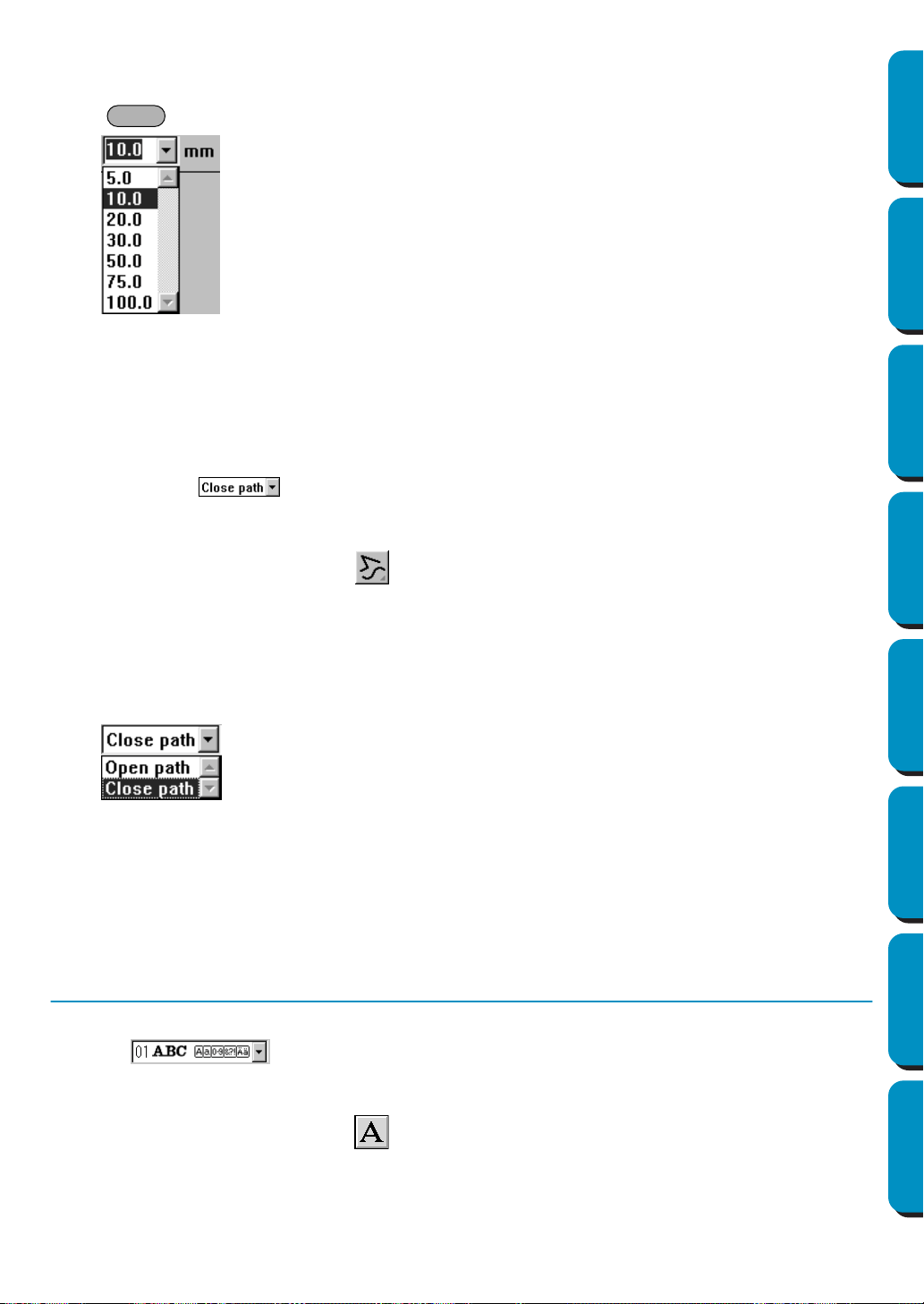
138
Contents Before Using Getting Started Design Center Layout & Editing
Programmable
Stitch Creator
Quick Reference Alphabetic Index
Operation:
1 Type the desired value on the Edge radius selector (0 - 100 mm or 0 - 3.93 inches) and press the
key or click on the Edge radius selector to display the available values.
2 Click the desired value.
The setting applies to all the patterns that you will create in the Rectangle Drawing mode until you
change the setting.
If a rectangle is selected, the setting also applies to that rectangle.
See also: “Rectangle Drawing Mode” on page 131
■ Path shape
Purpose: Opens and closes broken lines and curves.
Available: When you click on the Tool Box to start the outline Drawing mode.
When you select an existing broken line or curve with the cursor in Selection
mode.
Operation:
1 Click on the Path shape selector.
Two options are available.
2 Click the desired option.
The setting applies to all the patterns that you will create in the outline Drawing mode until you
change the setting.
If a broken line or curve is selected, the setting applies to that broken line or curve.
See also: “Outline Drawing Mode” on page 131
Setting Text Attributes
■ Font
Purpose: Selects a font for text.
Available: When you click on the Tool Box to start the Text Input mode.
When you select existing text patterns with the cursor in Selection mode.
When you select characters with the cursor in Point Edit mode.
Enter
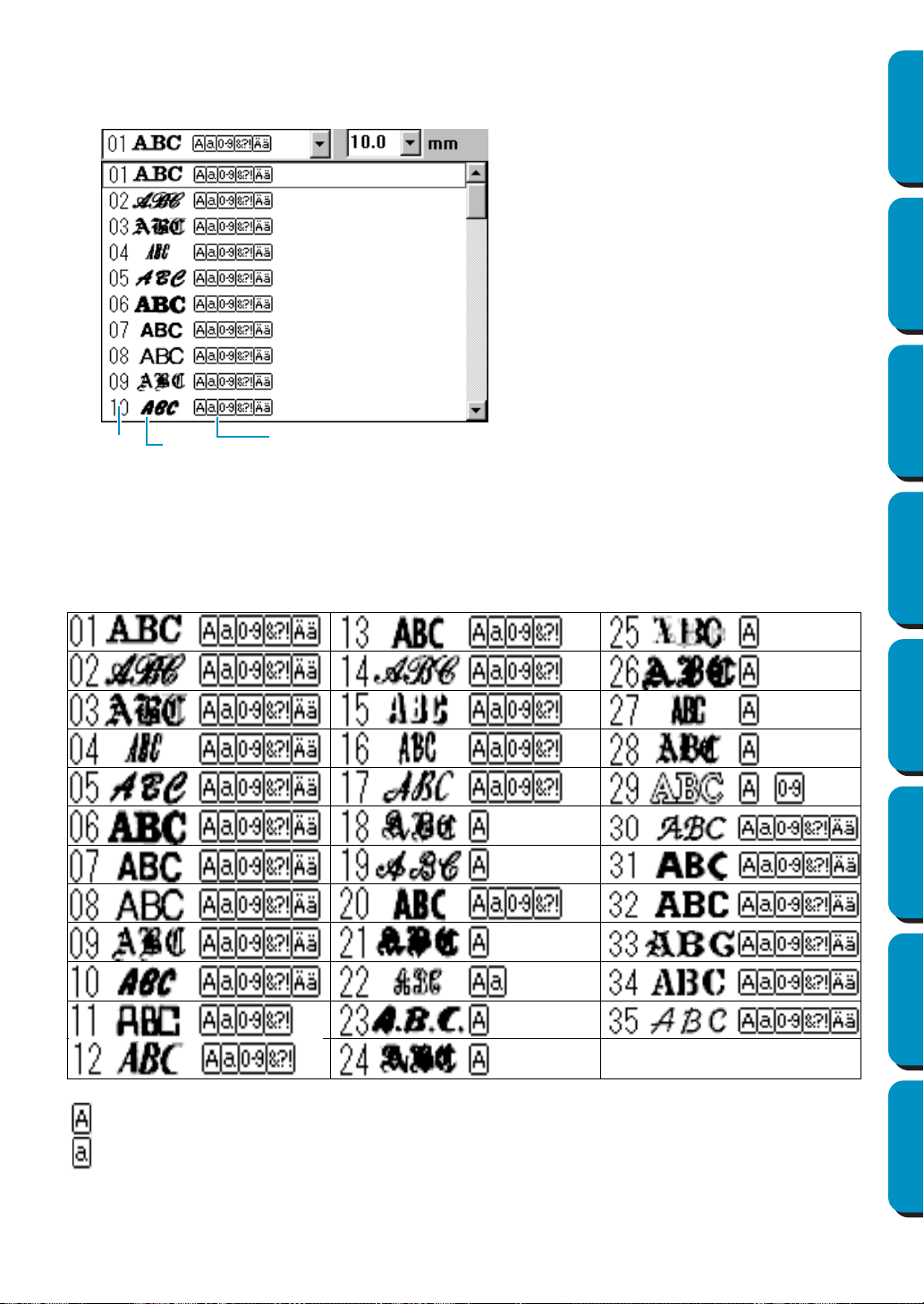
139
Contents Before Using Getting Started Design Center Layout & Editing
Programmable
Stitch Creator
Quick Reference Alphabetic Index
Operation:
1 Click on the Font selector.
A list of fonts displays.
2 Click the desired font.
The setting applies to all the text patterns that you will create in the Text Input mode until you change
the setting.
If text patterns or characters of a text pattern are selected, the setting also applies to the selection.
The following illustration shows the fonts available and, for each font, the kind of characters available:
Font
Font sample
Types of characters
number
available
Uppercase letters of the English alphabet
Lowercase letters of the English alphabet
Numerals
Punctuation, brackets and other symbols
Uppercase and lowercase accented letters
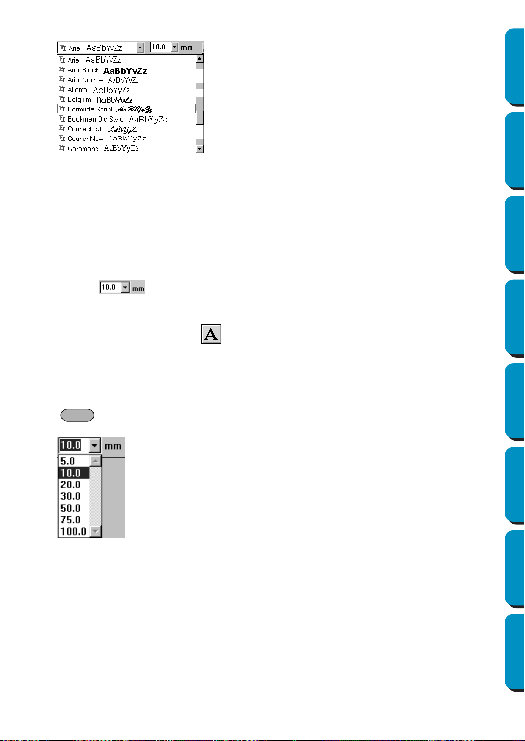
140
Contents Before Using Getting Started Design Center Layout & Editing
Programmable
Stitch Creator
Quick Reference Alphabetic Index
In addition, the names and samples of installed TrueType fonts appear after the fonts listed in the table above.
If one of these TrueType fonts are selected, the font data is automatically converted to embroidery data.
Font settings can be changed in the TrueType Font Attribute Setting dialog, which is displayed by click-
ing Text - TrueType Font Attribute Setting.
NOTE:
Some TrueType fonts may not convert well into beautiful embroidery data due to their design and
shape.
See also: “Text Input Mode” on page 127, “Point Edit Mode” on page 120, “TrueType Font
Attribute Setting” on page 202
■ Text size
Purpose: Selects the size for text.
Available: When you click on the Tool Box to start the Text Input mode.
When you select existing text patterns with the cursor in Selection mode.
When you select characters with the cursor in Point Edit mode.
Operation:
1 Type the desired value in the Text size selector (5 - 100 mm or 0.20 - 3.93 inches) and press the
key
or click on the Text size selector to display the available values.
2 Click the desired value.
The setting applies to all the text patterns that you will create in the Text Input mode until you
change the setting.
If a text pattern or characters of a text pattern are selected, the setting also applies to the selec-
tion.
See also: “Text Input Mode” on page 127, “Point Edit Mode” on page 120
Enter
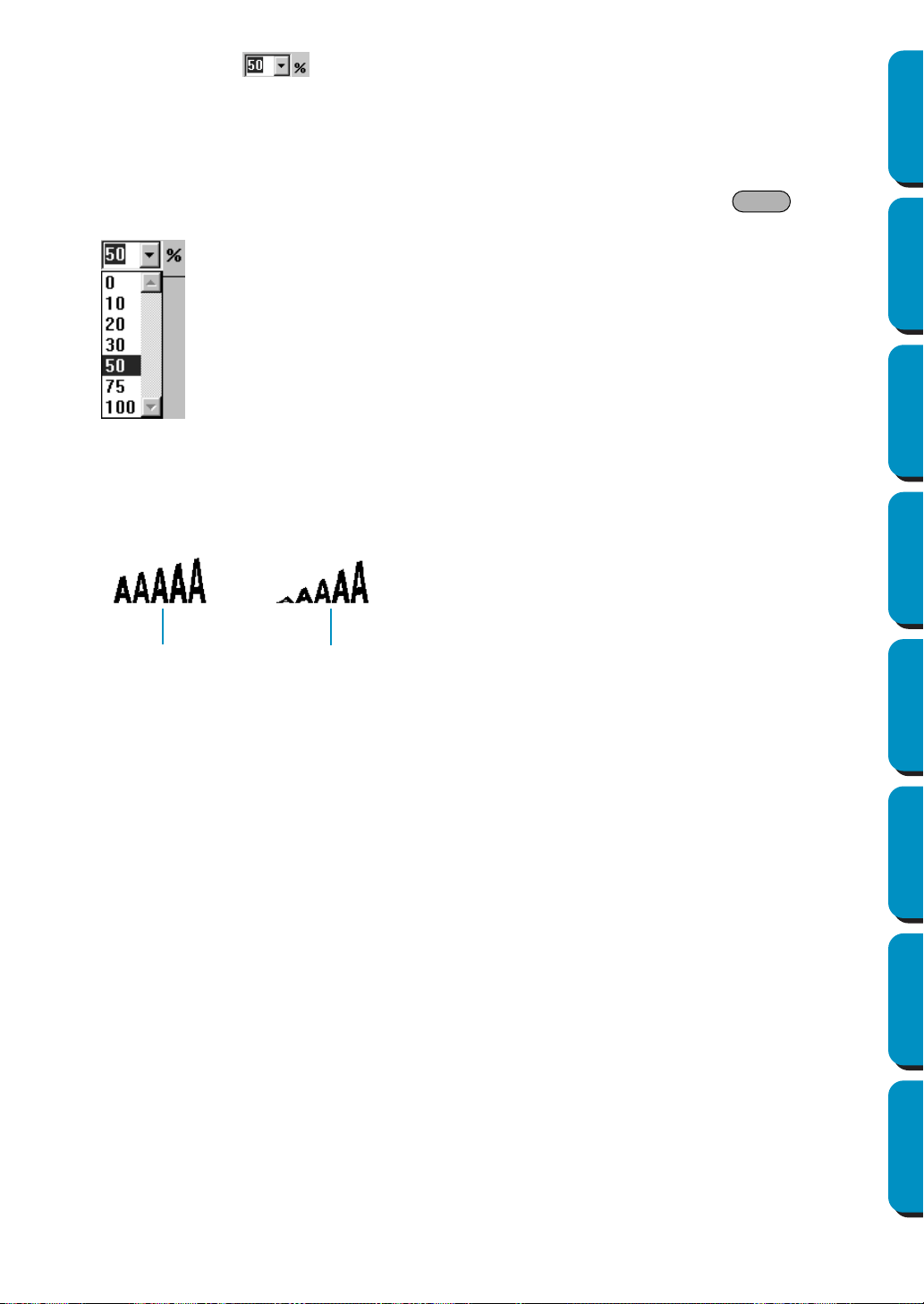
141
Contents Before Using Getting Started Design Center Layout & Editing
Programmable
Stitch Creator
Quick Reference Alphabetic Index
■ Transform level
Purpose: Selects the level of transformation.
Available: When you select an existing transformed text with the cursor in Selection mode.
Operation:
1 Type the desired value in the Transform level selector (0 - 100%) and press the key
or click on the Transform level selector to display the available values.
2 Click the desired value.
The setting applies to all the transformed text patterns that you will create in the Text Input mode
until you change the setting.
If a text pattern is selected, the setting also applies to the selection.
See also: “Text Input Mode” on page 127 and “Transform Text” on page 201
Enter
50%
100%
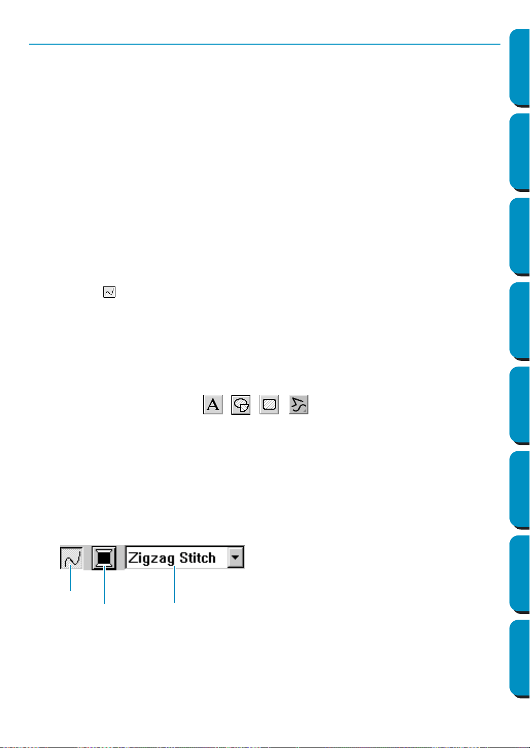
142
Contents Before Using Getting Started Design Center Layout & Editing
Programmable
Stitch Creator
Quick Reference Alphabetic Index
Setting the Thread Color and Stitch
All patterns can be assigned at least one color. Patterns with an outline and a region inside can be
assigned two different thread colors. Characters in a text pattern can be assigned individual thread col-
ors.
All patterns can be assigned at least one stitch type. Patterns with an outline and a region inside can be
assigned two different stitch types.
Patterns with an outline and a region inside are: Text converted from True Type Font, Circle, Fan Shape,
Arc & String, Rectangle, Closed Broken Line, and Closed Curve. For these patterns, it is possible to
switch the outline and the regions on and off.
Patterns with only an outline are: Arc, Open Broken Line, and Open Curve. For these patterns, it is still
possible to switch the outline on and off.
Patterns with only a region are: Text included this software, manual punch patterns and converted
imported patterns (to which the Stitch to block function has been applied). For those three types of pat-
terns, it is not possible to switch the region inside on and off.
Manual punch patterns: You can set a color to all three manual punch pattern types (block, running and
feed), but you can only set a stitch sew type to the block patterns.
Imported patterns converted with the Stitch to Block function: You can modify globally the sewing
attributes of the blocks of the same color.
■ Line sew
Purpose: Switches the outline on/off.
When the outline is switched off, it is not sewn (and you cannot set its color or
stitch).
Available: When the cursor is in Selection mode with nothing selected.
When you select a pattern that has an outline (Text converted from True Type
Font, Circle, Arc, Fan Shape, Arc & String, Rectangle, Broken Line, Curve)
When you click , , , on the Tool Box to start drawing such a
pattern.
Operation:
1 Click the Line sew button.
This button has two states:
on: the Line color button and the Line sew type selector are displayed
off: the Line color button and the Line sew type selector are not displayed.
Clicking the button toggles between the two states.
The setting applies to all the patterns with an outline that you will create until you change the set-
ting.
Line sew
Line color
Line sew type
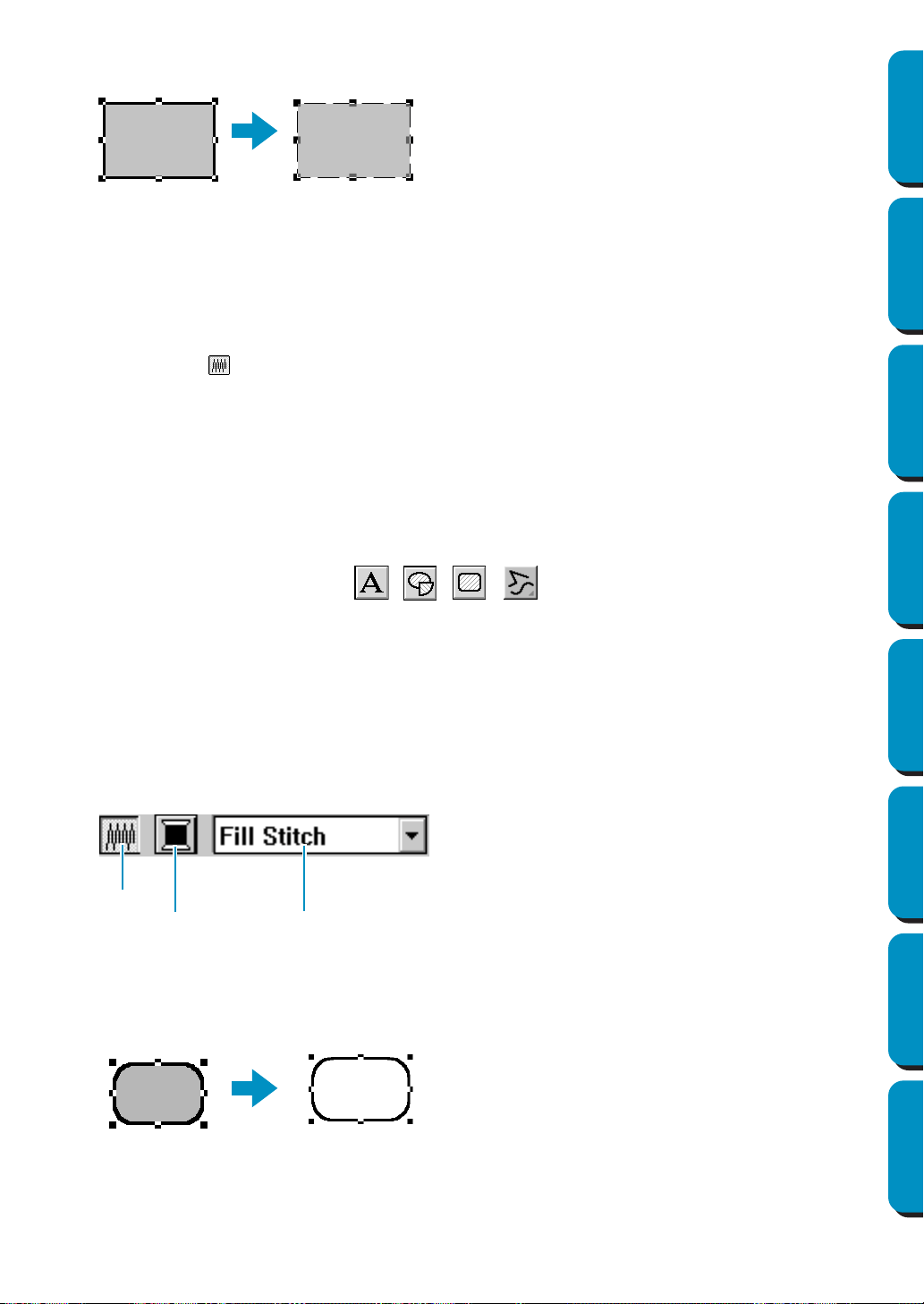
143
Contents Before Using Getting Started Design Center Layout & Editing
Programmable
Stitch Creator
Quick Reference Alphabetic Index
If a pattern is selected, the setting applies to that pattern.
Line sew on: Line sew off:
2 To restore the outline click the Line sew button again.
NOTE:
If the fonts included in this software (font number 1-35) are selected, the Line sew setting can not
be made.
See also: “Color” on page 144 and “Stitch” on page 146
■ Region sew
Purpose: Switches the inside region on/off.
When the inside region is switched off, it is not sewn (and you cannot set its color
or stitch).
Available: When the cursor is in Selection mode with nothing selected.
When you select a pattern that has an inside region (Text converted from True
Type Font, Circle, Fan Shape, Arc & String, Rectangle, closed Broken Line and
Curve)
When you click , , , on the Tool Box to start drawing such a
pattern.
Operation:
1 Click the Region sew button.
This button has two states:
on: the
Region color button and the Region sew type selector are displayed
off: the Region color button and the Region sew type selector are not displayed.
Clicking the button toggles between the two states.
The setting applies to all the patterns with an inside region that you will create until you change the
setting.
If a pattern is selected, the setting applies to that pattern.
2 To restore the inside region click the Region sew button again.
See also: “Color” on page 144 and “Stitch” on page 146
Region sew
Region color
Region sew type
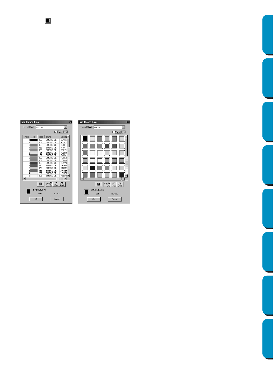
144
Contents Before Using Getting Started Design Center Layout & Editing
Programmable
Stitch Creator
Quick Reference Alphabetic Index
■ Color
Purpose: Sets the thread color for outline, region inside, text, manual punching pattern and
imported pattern (after the Stitch to Block function has been applied).
Available: When the cursor is in Selection mode with nothing selected, the Line color and
Region color buttons are displayed (if they have not been turned off with the Line
sew
or Region sew buttons).
When you start one of the drawing modes or Text Input mode, or select an existing
pattern, the Color button for the corresponding pattern appears.
Operation:
1 Click the Color button.
A Thread Color dialog similar to the one shown below appears.
Clear the View Details check box to view a list of only the thread colors.
The setting applies to all the patterns of the same categories that you will create until you change
it. The color button of each category shows the current color for that category.
If a pattern is selected, the setting also applies to that pattern.
NOTE:
For details on specifying a user thread chart or for information on how machines handle thread
colors, refer to “Edit User Thread Chart” on page 225.
See also: “Line sew” on page 142 and “Region sew” on page 143
◆ From the Thread Chart list, select a system
chart or a user thread chart.
◆ From the color list, select the desired color.
(The color can also be selected by double-
clicking it.)
• Descriptions for the four buttons under the list
are provided in “Special colors” on page 145.
◆ Click OK to confirm.
◆ Click
Cancel to exit.
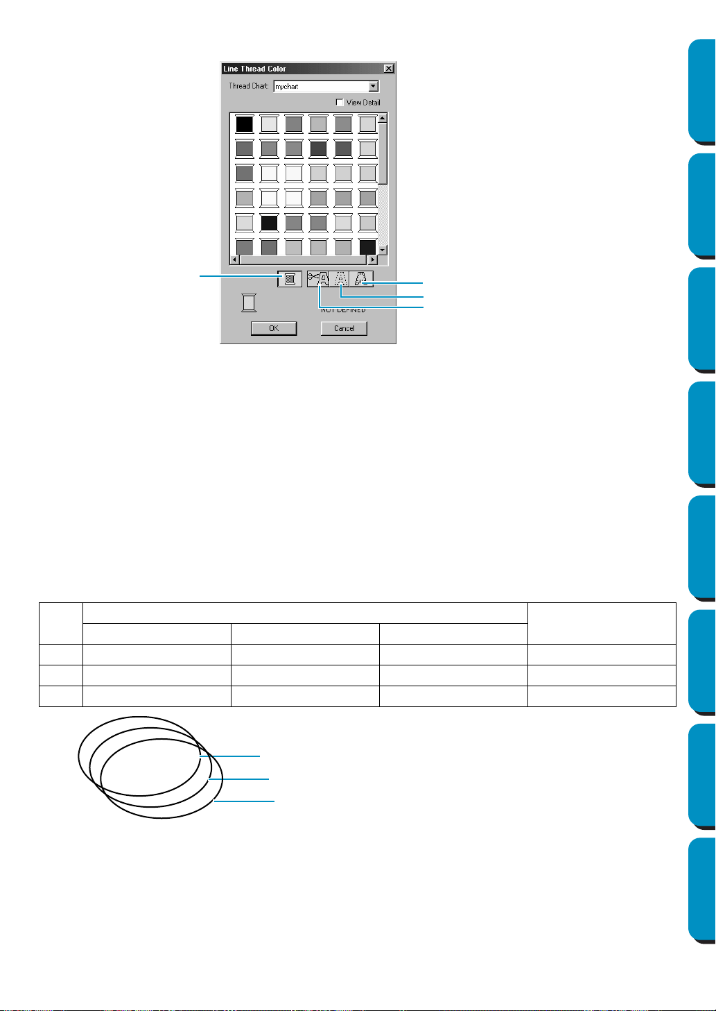
145
Contents Before Using Getting Started Design Center Layout & Editing
Programmable
Stitch Creator
Quick Reference Alphabetic Index
Special colors
◆
NOT DEFINED: Sewing machines that feature automatic thread color display will automatically switch
the display to the specified color. If you are using such a machine and if you wish to be able to select
manually the color for a monochrome pattern, you can select the “NOT DEFINED” color.
◆ Colors for creating appliqués: You can create appliqués using the three special colors shown in the
above illustration.
APPLIQUE MATERIAL marks the outline of the region to cut from the appliqué material.
APPLIQUE POSITION marks the position on the backing material where the appliqué must be sewn.
APPLIQUE sews the appliqué on the backing material.
Example:
1 Create an oval.
2 Duplicate the oval and move it apart from the first one. Repeat this step to obtain a total of three
identical ovals.
3 Select the ovals one by one and make the following settings:
Oval
Sewing Attributes bar
Sewing Attributes
Region sew button Line color Line sew type
1 OFF APPLIQUE MATERIAL Running RUN TIME = 1
2 OFF APPLIQUE POSITION Running RUN TIME = 1
3 OFF APPLIQUE Zigzag –
NOT DEFINED
APPLIQUE MATERIAL
APPLIQUE POSITION
APPLIQUE
APPLIQUE MATERIAL
APPLIQUE POSITION
APPLIQUE
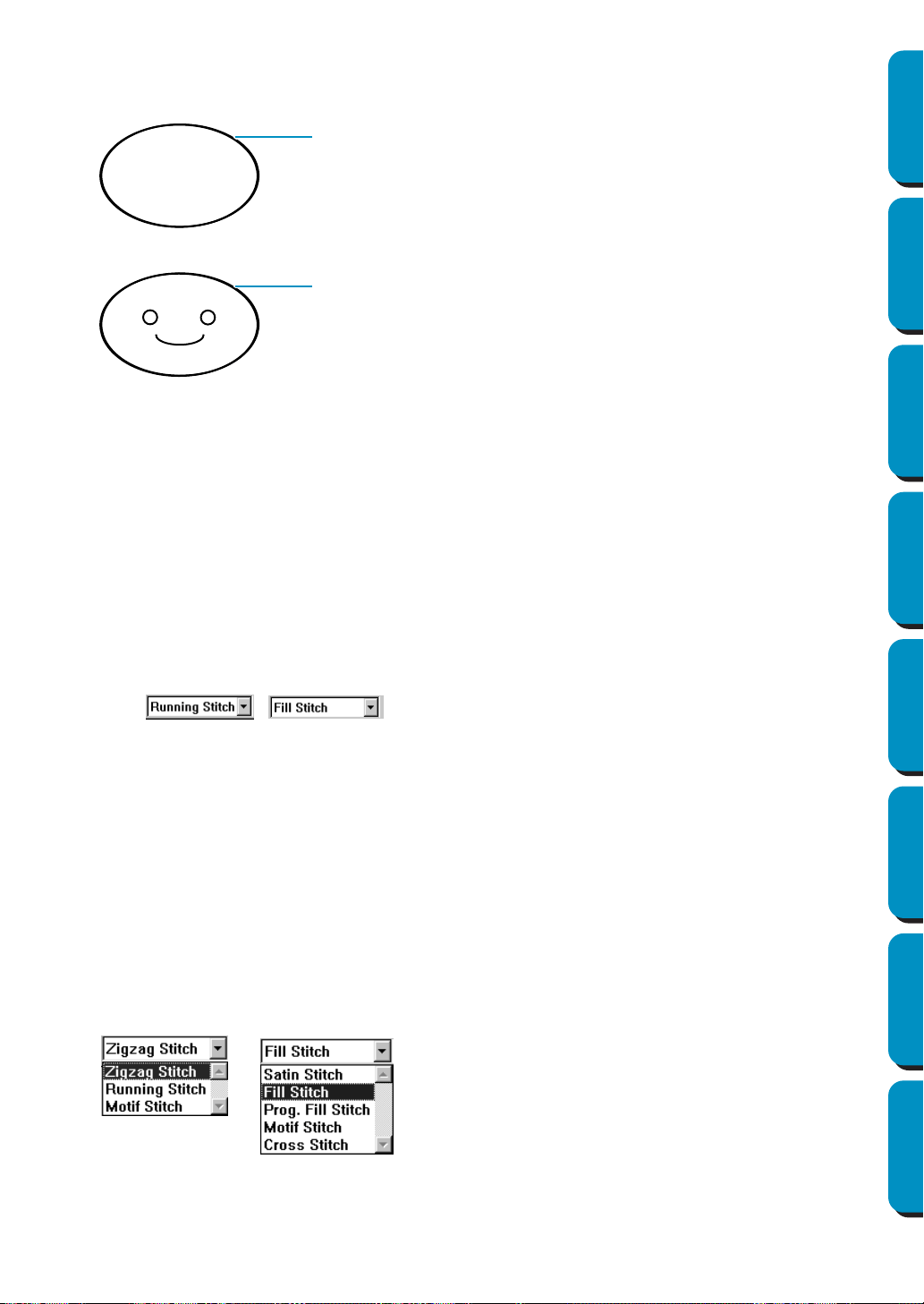
146
Contents Before Using Getting Started Design Center Layout & Editing
Programmable
Stitch Creator
Quick Reference Alphabetic Index
4 Bring the APPLIQUE POSITION oval and the APPLIQUE oval at the same position as the APPLIQUE
MATERIAL
oval (using the grid can make this operation easier). You can confirm the appliqué posi-
tion using the preview function (see “Preview” on page 220).
5 Add details as you would with a normal embroidery picture.
When sewing, proceed as follows:
1 Place the appliqué material on the machine and start sewing. At this step, only the APPLIQUE
MATERIAL
outline will be sewn.
2 Remove the appliqué material from the machine and cut along the outline.
3 Place the backing material on the machine and start sewing. At this step, only the APPLIQUE POSI-
TION
outline will be sewn.
4 Affix the appliqué on the marked position with a small amount of fabric glue.
5 Restart sewing. At this step, the APPLIQUE outline will be sewn.
6 Sew the other details of the picture.
Note that the sewing order will be MATERIAL → POSITION → APPLIQUE.
■ Stitch
Purpose: Sets the stitch for outline, region inside, text, manual punching pattern and
imported pattern (after the Stitch to Block function has been applied).
Available: When the cursor is in the selection mode, the Line sew type and Region sew type
selectors are displayed (if they have not been turned off with the Line sew or
Region sew buttons).
When you start one of the drawing modes or select an existing pattern, the sew
type button for that pattern appears.
When you are in the text or manual punching mode or after applying a Stitch to
block setting to an imported pattern.
Operation:
1 Click the sew type selector.
The available options display.
For outlines, Zigzag Stitch, Running Stitch and Motif Stitch are available.
For regions, Satin Stitch, Fill Stitch, Programmable Fill
Stitch
, Motif Stitch and Cross Stitch are avail-
able.
APPLIQUE MATERIAL / APPLIQUE POSITION / APPLIQUE
APPLIQUE MATERIAL / APPLIQUE POSITION / APPLIQUE

147
Contents Before Using Getting Started Design Center Layout & Editing
Programmable
Stitch Creator
Quick Reference Alphabetic Index
2 Click the desired stitch.
The setting applies to all the patterns of the same categories that you will create until you change it.
If a pattern is selected, the setting also applies to that pattern.
NOTE:
You can set the stitch attributes for the selected line and region stitches in the
Sewing attribute Set-
ting
dialog.
When you select Prog. fill Stitch or Motif Stitch, you also need to select a pattern in the Sewing
Attribute Setting
dialog, as there is no default programmable stitch setting.
See also: “Line sew” on page 142, “Region sew” on page 143 and “Sewing Attribute Setting”
on page 204
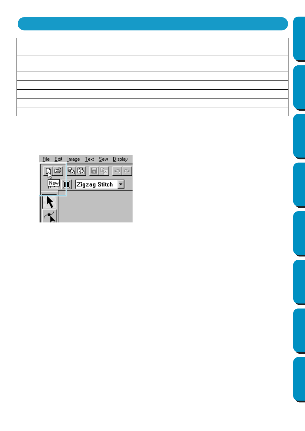
148
Contents Before Using Getting Started Design Center Layout & Editing
Programmable
Stitch Creator
Quick Reference Alphabetic Index
Most functions available on the menu can also be activated by clicking a button on the Toolbar or by
pressing a shortcut key or key combination.
When you leave the cursor for a while on a button of the Toolbar, a label indicating the function of the but-
ton displays.
File Handles file input/output, such as opening, saving and printing. page 149
Edit Performs simple actions on selected patterns, such as cutting and pasting. page 166
Image
Imports and exports image data and creates embroidery data from image
data.
page 175
Text Performs actions on text patterns, such as fitting text to a curved path. page 197
Sew Defines how each pattern will be sewn. page 204
Display Modifies the appearance of the screen. page 219
Option Provides additional options. page 223
Help Gives you access to the on-screen help information system. page 230
Using the Menu Bar and the Toolbar
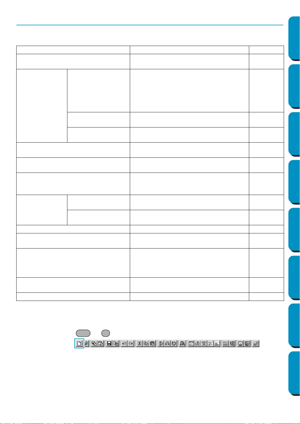
149
Contents Before Using Getting Started Design Center Layout & Editing
Programmable
Stitch Creator
Quick Reference Alphabetic Index
File Menu
The File menu handles file input/output, such as opening, saving and printing.
■ New
Purpose: Creates a new blank Design Page.
Shortcut key: +
Toolbar:
Operation:
1 Click File, then New.
If the current Design Page is not edited, a new blank Design Page appears immediately.
New Creates a new blank Design Page. page 149
Open
Opens a previously saved Design Page file
(*.pes file).
page 150
Import
from File
Imports embroidery patterns from embroi-
dery cards (*.pec), original cards (*.pes)
and files created in the Tajima (*.dst), Melco
(*.exp), Pfaff (*.pcs) and Husqvarna (*.hus)
formats and adds them to your current
Design Page.
page 151
from Design Center
Imports an embroidery pattern from Design
Center.
page 153
from Card
Imports an embroidery pattern from an
embroidery card.
page 154
Save
Saves your Design Page on the disk as a
latest version file (default).
page 156
Save As
Saves your Design Page on the disk under
a new file name.
page 156
Export
Exports the data shown in the Design Page
as a file of a different format (dst, hus, exp,
and pcs).
page 157
Write to Card
Current Design
Writes your Design Page to an original
card.
page 157
Other PES files
Writes multiple PES files to an original card
at the same time.
page 158
Property To enter comments in a saved PES file. page 161
Print Setup
Allows you to change the printing settings
for previewed embroideries.
page 161
Print Preview
Allows you to preview the contents of the
Design Page and check the sewing color
order, the dimensions and the needle count
before printing.
page 163
Print
Prints your Design Page and some sewing
information.
page 164
Exit Exits the application. page 165
Ctrl N
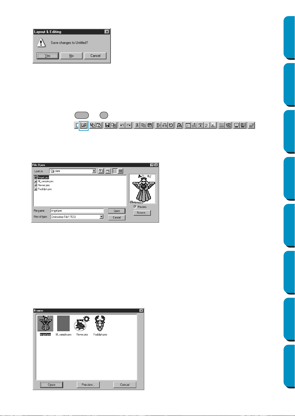
150
Contents Before Using Getting Started Design Center Layout & Editing
Programmable
Stitch Creator
Quick Reference Alphabetic Index
2 If the current Design Page is edited, you will be asked whether you want to save the changes.
See also: “Open” below and “Save” and “Save As” on page 156
■ Open
Purpose: Opens a previously saved Design Page file (*.pes file).
Shortcut key: +
Toolbar:
Operation:
1 Click File, then Open.
A File Open dialog similar to this will display.
2 If you choose to browse, a Browse dialog similar to this will display:
◆ Click Yes to save the Design Page first.
◆ Click No to abandon the Design Page.
◆ Click
Cancel to do anything else (for example,
modify the current Design Page or saving it
with another file name).
◆ Select the drive, the folder and the file
name.
• Be sure to select a folder containing
pes
files.
• The contents of the selected file dis-
plays in the
Preview window, provided
its check box is checked.
◆ Click
Open or double click the file
name. The file will appear on the
Design Page.
◆ You can also select the drive and folder
only and then click Browse to display a
graphic contents of the currently
selected folder (provided it contains
*.pes files).
◆ Click Cancel to exit.
◆ To select a file, click on its icon.
◆ To open the file, click
Open or double-
click the icon.
◆ To see a more detailed image, click
Pre-
view
.
◆ To return to the
File Open dialog, click
Cancel.
Ctrl O
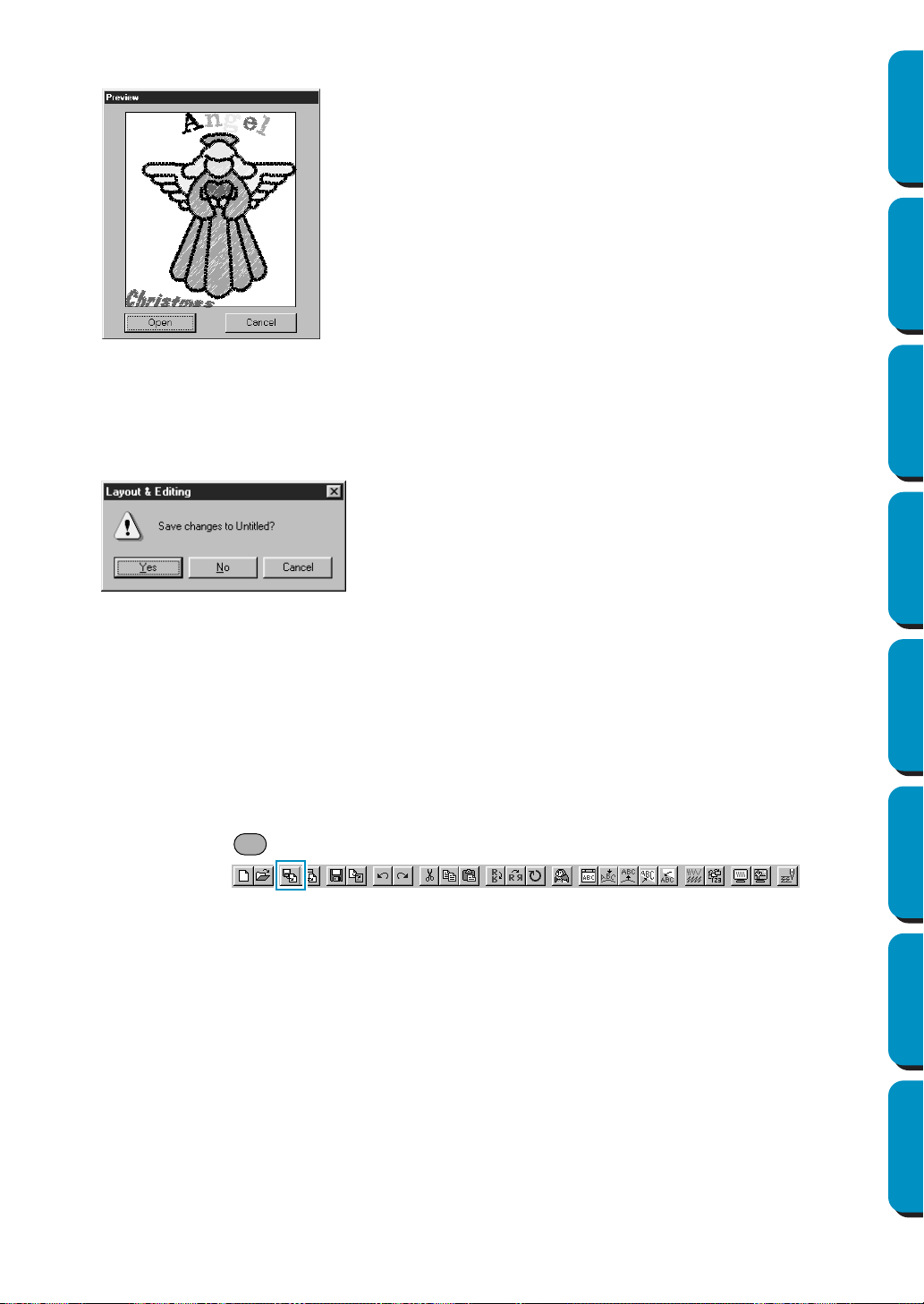
151
Contents Before Using Getting Started Design Center Layout & Editing
Programmable
Stitch Creator
Quick Reference Alphabetic Index
3 If you choose to preview, a Preview dialog similar to this will display.
4 When you click Open while viewing the File Open, Browse or Preview dialog, the selected file opens
immediately if your current Design Page is not edited.
If the current Design Page is edited, you will be asked whether you want to save the changes.
Note that parts of the embroidery picture which are not within the Design Page cannot be pre-
viewed.
See also: “New” on page 149, “Save” and “Save As” on page 156
■ Import – from File
Purpose: Imports embroidery patterns from embroidery cards (*.pec), original cards (*.pes)
and files created in the Tajima (*.dst), Melco (*.exp), Pfaff (*.pcs) and Husqvarna
(
*.hus) formats and adds them to your current Design Page.
Shortcut key:
Toolbar:
◆ Click Open to open the file.
◆ Click Cancel to return to the Browse dialog.
◆ Click Yes to save the Design Page first.
◆ Click No to abandon the Design Page.
◆ Click
Cancel to do anything else (for example,
modifying the current Design Page or saving it
with another file name).
F8
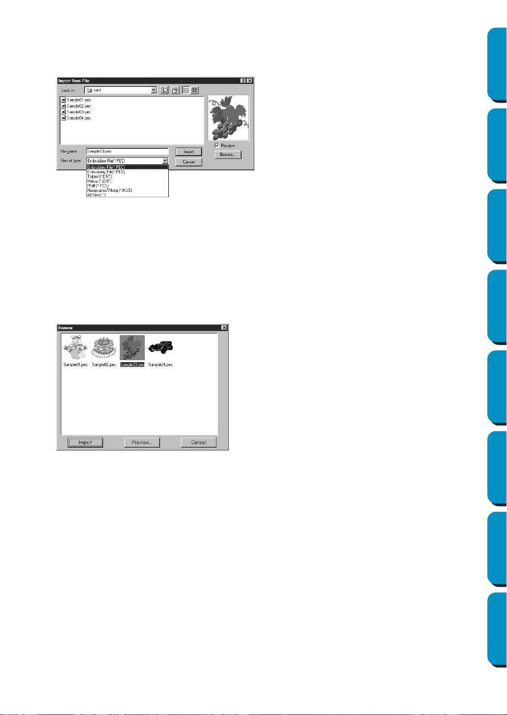
152
Contents Before Using Getting Started Design Center Layout & Editing
Programmable
Stitch Creator
Quick Reference Alphabetic Index
Operation:
1 Click File, then Import, then from File.
An
Import from File dialog similar to this displays.
2 If you choose to browse, a Browse dialog similar to this will display:
◆ Select the drive, the folder and the file
name.
• Be sure to select the right type of file
extension in
Files of Type.
• If the Preview check box is checked,
the content of the selected file displays
in the preview window.
◆ Click
Import or double-click the file
name to display the file on the Design
Page.
◆ You can also select the drive and folder
only and then click Browse to display a
graphic contents of the currently
selected file format.
◆ Click Cancel to exit.
◆ To select a file, click on its icon.
◆ To open the file, click Import or double-click the
icon.
◆ To see a more detailed image, click
Preview.
◆ To return to the
Import from File dialog, click
Cancel.
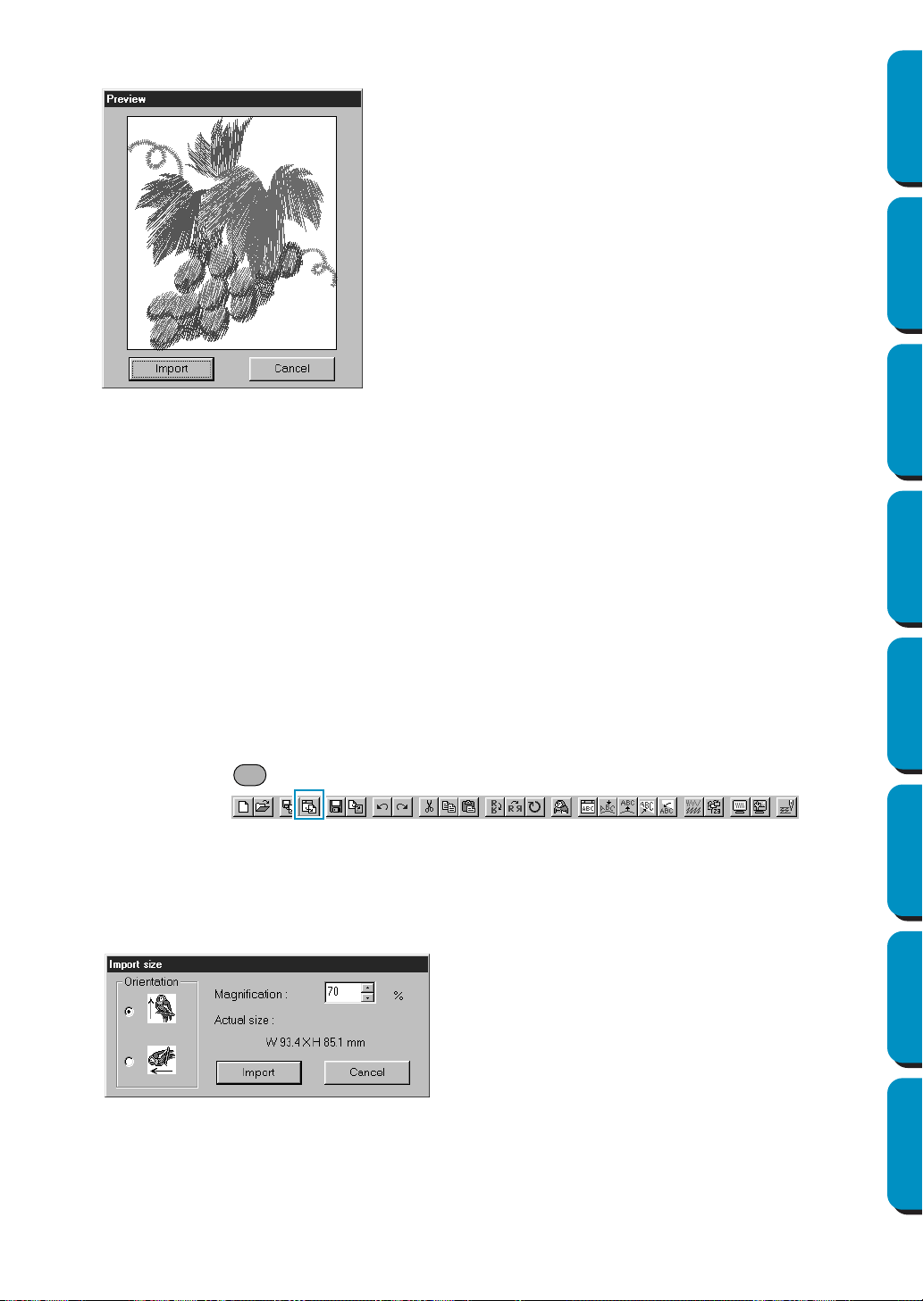
153
Contents Before Using Getting Started Design Center Layout & Editing
Programmable
Stitch Creator
Quick Reference Alphabetic Index
3 If you choose to preview, a Preview dialog similar to this will display.
When you import a file, its contents are added to your current Design Page. You can repeat the
operation and assemble your Design Page from a library of patterns that you have created.
NOTE:
When importing patterns from other makers, make sure to choose a pattern whose size will fit in
the Design Page.
When converted for this application, the colors of patterns imported from
dst (Tajima), exp (Melco),
pcs
(Pfaff) and Hus (Husqvarna) files may be slightly changed. When this happens, you can
change the color with the Sew – Change colors of a stitch object function.
4 When importing some pec files from embroidery cards, the Select Import size dialog will display. If
this happens, select the import size by clicking the appropriate radio button, then click OK to
import the data.
See also: “Save As” on page 156
■ Import – from Design Center
Purpose: Imports an embroidery pattern from Design Center.
Shortcut key:
Toolbar:
Operation:
1 Start Design Center and open the file that you want to import into Layout & Editing.
2 Click File, then Import, then from Design Center.
The
Import size dialog displays.
◆ Click Import to import the file.
◆ Click Cancel to return to the Browse dialog.
◆ Select the magnification factor. You can type it
or increase/decrease it using the arrow but-
tons.
• The application will not allow you to magnify
the embroidery data to a size such that it
would not fit in your Design Page area.
◆ Select the Orientation by clicking the Orienta-
tion
radio button opposite the appropriate icon.
◆ Click Import to import the data.
◆ Click Cancel if you want to exit the function.
F7
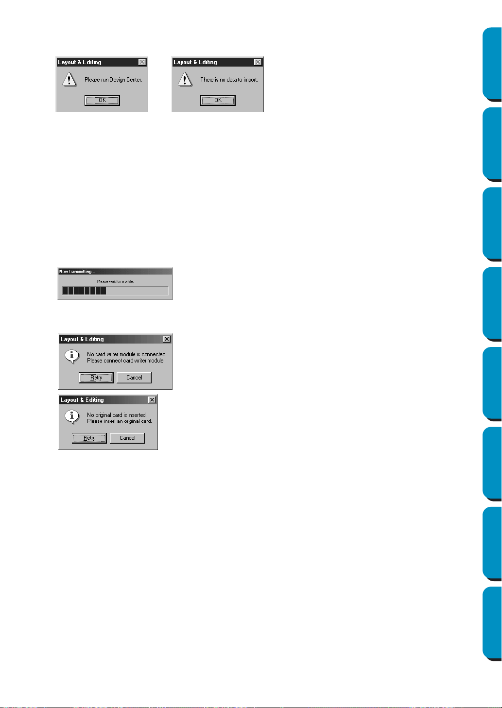
154
Contents Before Using Getting Started Design Center Layout & Editing
Programmable
Stitch Creator
Quick Reference Alphabetic Index
3 If you are not running Design Center or if it does not contain a pem file, the first or the second mes-
sage will appear.
See also: “Design Center” on page 61
■ Import – from Card
Purpose: Imports an embroidery pattern from an embroidery card.
Shortcut key: No shortcut key for this function
Toolbar: No button for this function
Operation:
1 Click File, then Import, then from Card.
If a card writer module is connected and if an embroidery card is inserted into the card writer mod-
ule, the following message appears and the embroidery patterns are read from the card.
If a card writer module is not connected or if one is connected but an embroidery card is not
inserted, one of the following messages appear.
◆ Click OK to exit.
◆ Correct the problem, and then click
Retry
.
◆ Click Cancel if you want to quit the opera-
tion.
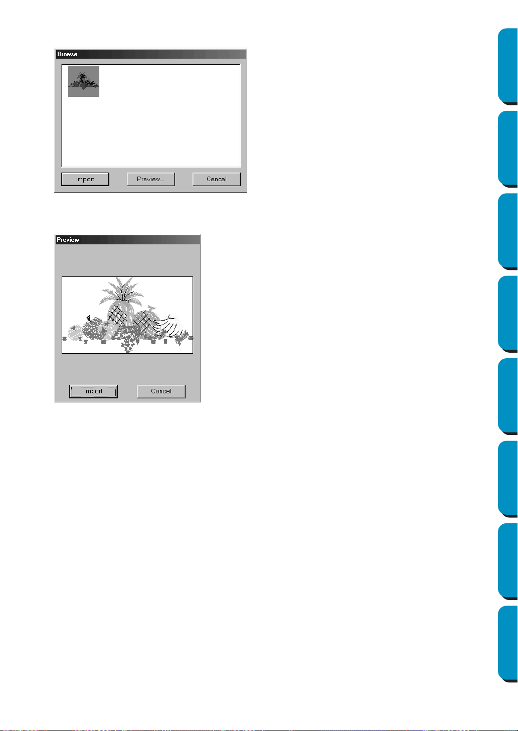
155
Contents Before Using Getting Started Design Center Layout & Editing
Programmable
Stitch Creator
Quick Reference Alphabetic Index
2 After the data has been read, the following dialog appears.
3 If you choose to preview a pattern, a Preview dialog similar to this will appear.
4 While importing some patterns, the Select Import size dialog may appear. If this happens, select
the import size by clicking the appropriate radio button, and then click OK to import the pattern.
NOTE:
Due to copyright issues, some embroidery cards cannot be used with this function.
◆ To select a pattern, click on its icon or drag
the pointer over it.
◆ To import a pattern, click
Import
or double-
click the pattern icon.
◆ To see a more detailed image of the pattern,
click
Preview
.
◆ Click Cancel if you want to quit the opera-
tion.
◆ Click
Import
to import the pattern.
◆ Click Cancel to return to the previous dia-
log.
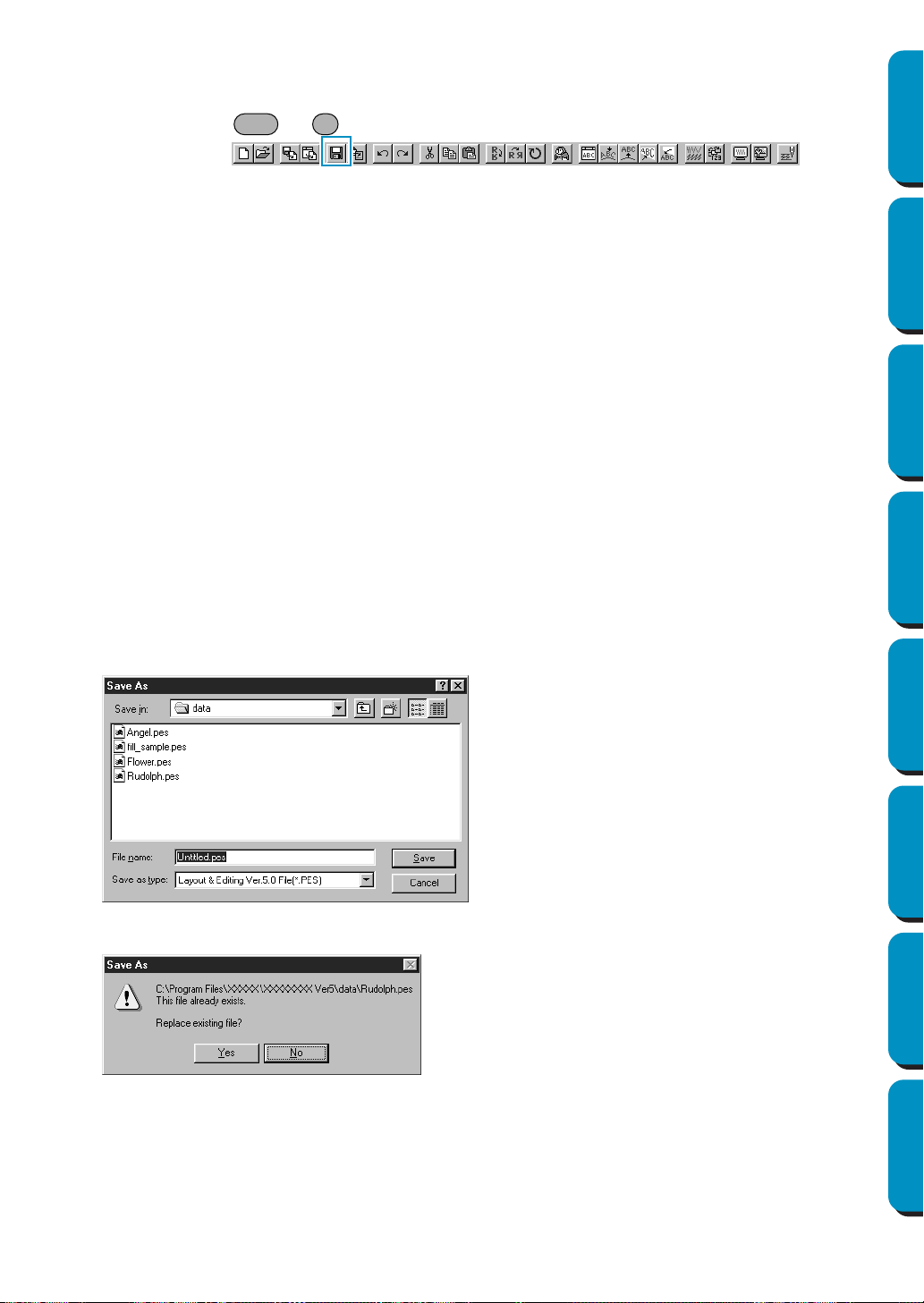
156
Contents Before Using Getting Started Design Center Layout & Editing
Programmable
Stitch Creator
Quick Reference Alphabetic Index
■ Save
Purpose: Saves your Design Page on the disk as a latest version file (default).
Shortcut key: +
Toolbar:
Operation:
1 Click File, then Save.
If the file already exists on the disk (the file has been saved at least once), the file is saved imme-
diately.
2 If the file name is still Untitled or if, for any other reason, the file cannot be found on the disk, the
application automatically switches to
Save As.
See also: “Save As” below, “Write to Card – Current Design” on page 157
■ Save As
Purpose: Saves your Design Page on the disk under a new file name.
NOTE:
If you select a previous version, saved *.pes files can be opened with a previous
version of the software. However, all saved data will be converted to stitch data.
Shortcut key: No shortcut key for this function
Toolbar: No button for this function
Operation:
1 Click File, then Save As.
A
File Save As dialog similar to this will display.
2 If the new file name already exists, this message will appear:
The new file name displays in the title bar of the Layout & Editing window.
See also: “Save” above and “Write to Card – Current Design” on page 157
◆ Select the drive, the folder and type the
file name.
◆ Click Save to save.
◆ Click Cancel to exit.
◆ Click Yes to overwrite.
◆ Click
No if you do not want to overwrite
the existing file.
Ctrl S
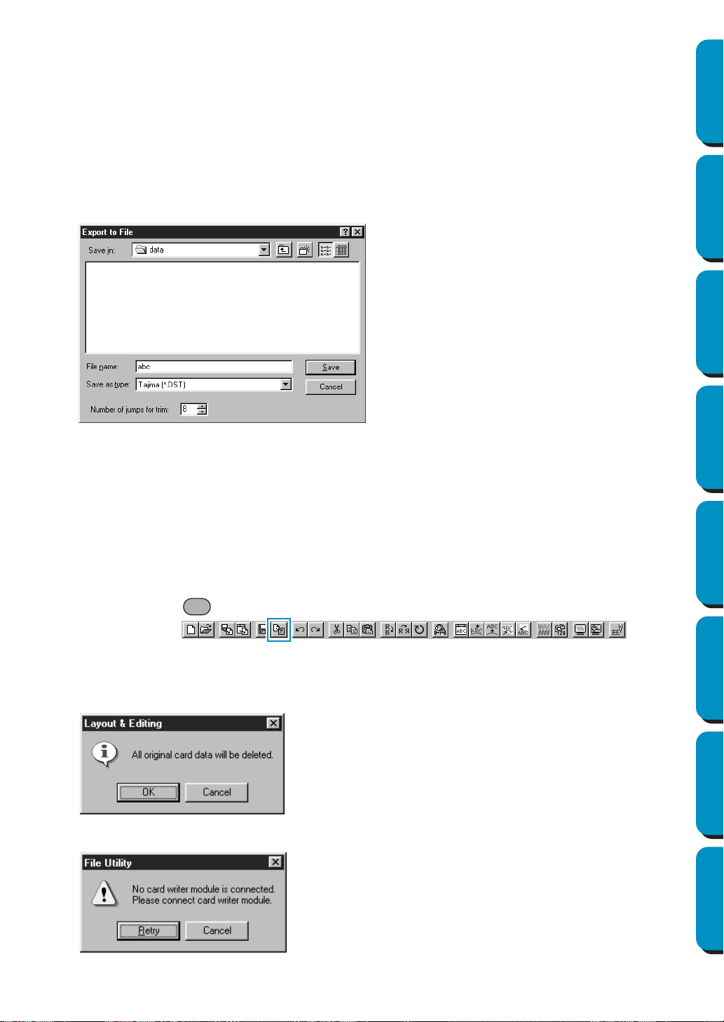
157
Contents Before Using Getting Started Design Center Layout & Editing
Programmable
Stitch Creator
Quick Reference Alphabetic Index
■ Export
Purpose: Exports the data shown in the Design Page as a file of a different format (dst, hus,
exp, and pcs).
Shortcut key: No shortcut key for this function
Toolbar: No button for this function
Operation:
1 Click File, then Export.
A dialog like the one shown below appears.
NOTE:
Some patterns installed from a card cannot be exported.
■ Write to Card – Current Design
Purpose: Writes your Design Page to an original card.
Shortcut key:
Toolbar:
Operation:
1 Click File, then Write to Card, then Current Design.
This message will display.
If the card module is not connected, this message displays.
◆ Select the drive and the folder,
and then type the file name.
◆ Select the format
(DST,EXP,PCS,HUS) in which
you wish to export the file.
◆ Number of jumps for trim:
With the DST format, jump codes are
used to indicate when the thread
must be cut in order to change the
thread color. Since the number of
codes differ depending on the sewing
machine being used, this setting
allows you to select the appropriate
value. (This setting can only be speci-
fied if the DST format is selected.)
◆ If the card is not brand new, make sure
that you want to erase the data that is
already stored on the card and click OK.
◆ Click Cancel to exit.
◆ Correct the problem, then click Retry.
◆ Click
Cancel to exit.
F4
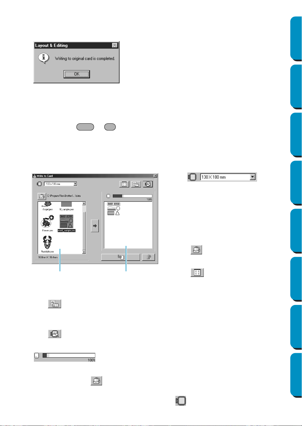
158
Contents Before Using Getting Started Design Center Layout & Editing
Programmable
Stitch Creator
Quick Reference Alphabetic Index
2 If you click OK, your current embroidery patterns will be saved on the card. A Now writing message
displays while the data is being transferred to the card.
After a while, the following message will appear.
See also: “Save” and “Save As” on page 156
■ Write to Card – Other PES files
Purpose: Writes multiple PES files to an original card at the same time.
Shortcut key: +
Toolbar: No button for this function
Operation:
1 Click File, then Write to Card, then Other PES files.
This following dialog appears.
◆ Click
to display the information (size, number of stitches, and colors) for the pattern selected
in the Available patterns list or the Selected patterns list. This is available only if one pattern is
selected.
◆ Click
to display a three-dimensional image of the pattern selected in the Available patterns
list or the Selected patterns list.
◆
shows the capacity of the patterns selected in the Selected patterns list.
◆ The Available patterns list [A] displays the images of the pattern files (.pes) saved in the folder
selected after clicking . The name of the file appears below the image.
• Patterns that are either too large or have too many stitches for the embroidery hoop size, selected
with the Hoop size selector, are crossed out with a red .
◆ Click OK.
◆
Use to select
the size of the embroidery hoop that can be
used with your embroidery machine.
NOTE:
Do not select a hoop size larger than the
embroidery hoop that can be used with
your embroidery machine. Otherwise, the
created card will not work correctly with
the embroidery machine.
◆ Click
, and then s
elect the folder
where the pattern file (.pes) is saved.
◆ Click
to switch between the large
and small display size of the pattern
images shown in the lists.
Shift F4
[A]
[B]
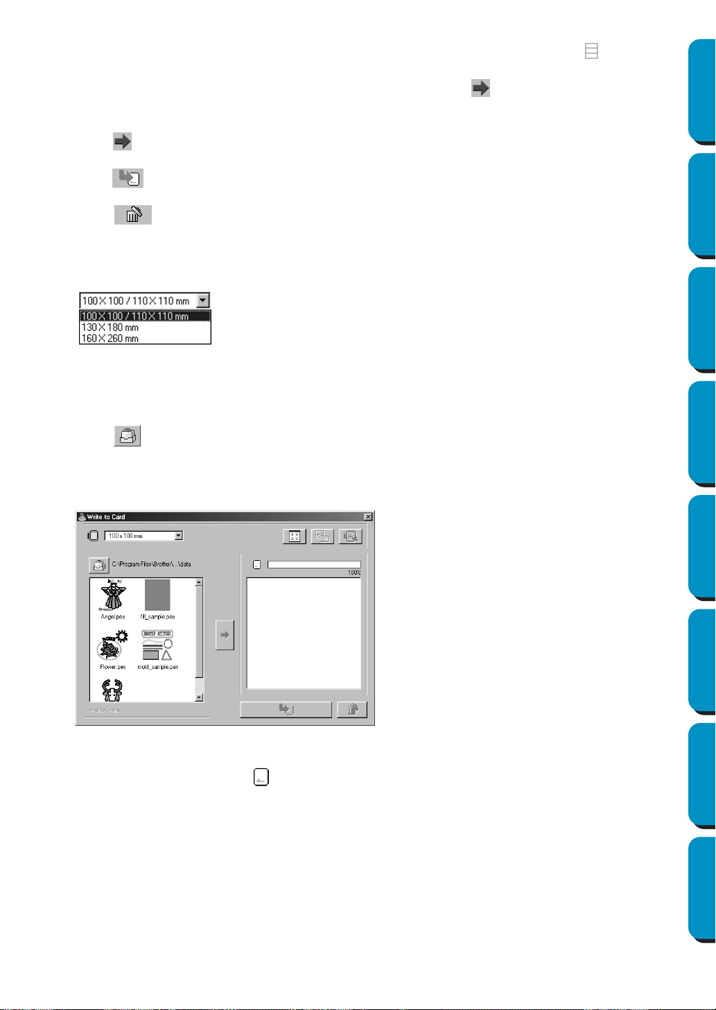
159
Contents Before Using Getting Started Design Center Layout & Editing
Programmable
Stitch Creator
Quick Reference Alphabetic Index
• Patterns created for the optional extra-large embroidery hoop are marked with the symbol.
◆ The Selected patterns list [B] displays the patterns selected with . The data will be written to an
original card in the order displayed.
◆ Click
to add the pattern selected in the Available patterns list to the Selected patterns list.
◆ Click
to write to an original card the patterns displayed in the Selected patterns list.
◆ Click
to remove the pattern selected in the Selected patterns list.
2 With the Hoop size selector, select the size of the embroidery hoop that can be used with your
embroidery machine.
NOTE:
Do not select a hoop size larger than the embroidery hoop that can be used with your embroidery
machine. Otherwise, the created card will not work correctly with the embroidery machine.
3 Click . The Folder dialog appears. Select the folder where the pattern file (.pes) is saved, and
then click OK.
Images and file names for the patterns files saved in the selected folder appear in the Available
patterns list.
• If an original card was selected , the patterns saved on the inserted card can be seen.
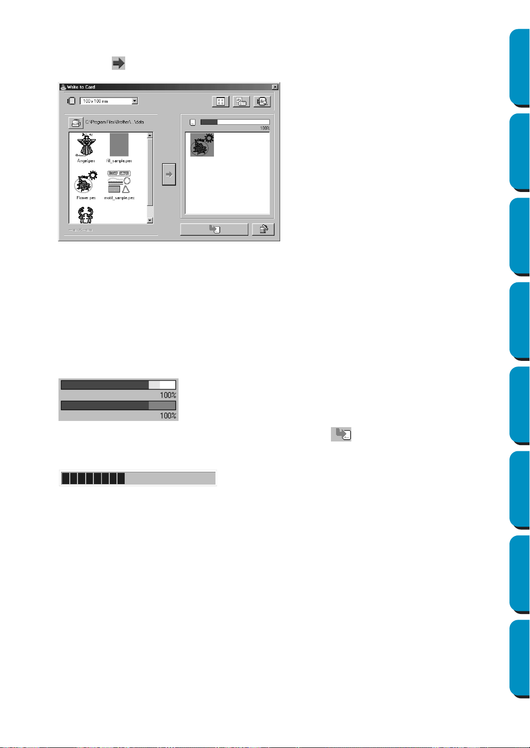
160
Contents Before Using Getting Started Design Center Layout & Editing
Programmable
Stitch Creator
Quick Reference Alphabetic Index
4 From the Available patterns list, click the pattern that you want to write to the card. The highlighted
pattern is selected.
Then, click to add the selected pattern to the Selected patterns list.
5 Continue this operation for all patterns that you wish to write to an original card. Viewing the Card
capacity indicator during this process will allow you to plan which designs you would like to save
an original card.
Reading the Card capacity indicator:
The part indicating selected patterns is shown in blue, and the part indicating the pattern being
selected is shown in light blue.
If the part indicating the pattern being selected appears in red, the size of the selected patterns
has exceeded the capacity of an original card.
6 After the patterns to be written to the card are selected, click to write the data to the card. The
data is written to an original card after all data already on the card is erased.
After a short while, the data is finished writing to an original card. Now, the card containing the
data can be used with the embroidery machine.
• If there are any patterns on the card that you do not wish to erase, be sure to select the card in the
Folder dialog box, and then add the patterns to the Selected patterns list.
• Do not remove the card or unplug the USB cable while data is being written to the card (while the LED
indicator is flashing).
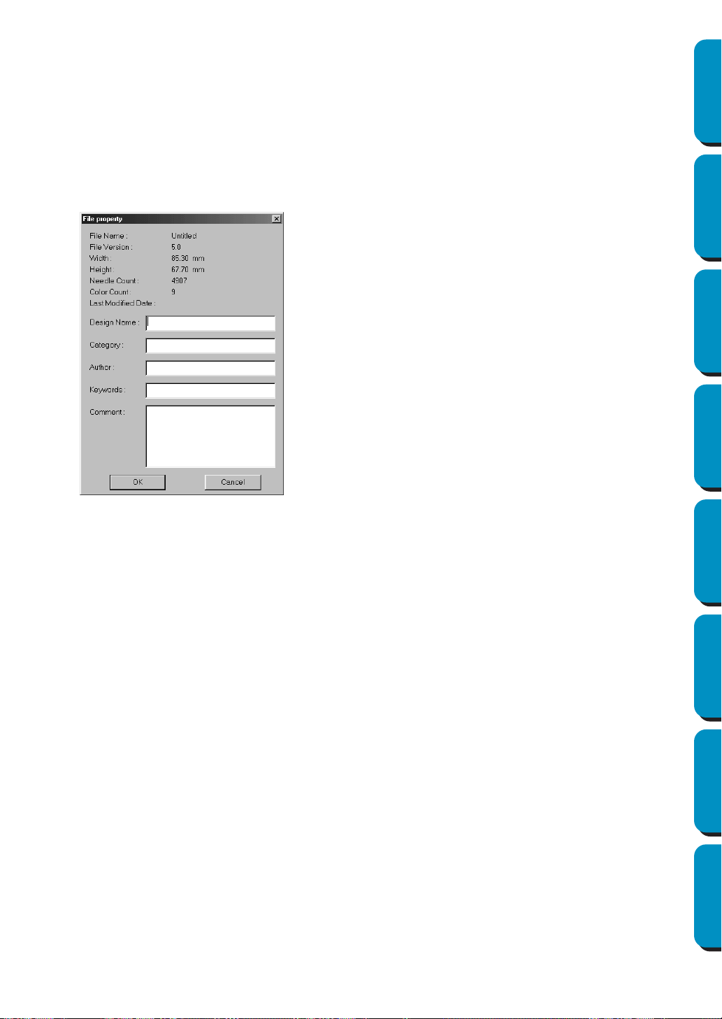
161
Contents Before Using Getting Started Design Center Layout & Editing
Programmable
Stitch Creator
Quick Reference Alphabetic Index
■ Property
Purpose: To enter comments in a saved PES file.
Shortcut key: No shortcut key for this function
Toolbar: No button for this function
Operation:
1 Click File, then Property.
The File Property dialogue appears.
■ Print Setup
Purpose: Allows you to change the printing settings for previewed embroideries.
Shortcut key: No shortcut key for this function
Toolbar: No button for this function
◆ Enter or revise the necessary
points in text format.
Design Name, Category, Author,
Keywords, and Comment.
◆ Click OK to save the entered data
and finish.
The entered data will be saved to
the file the next time you Save.
◆ Click Cancel to finish without sav-
ing the entered data.
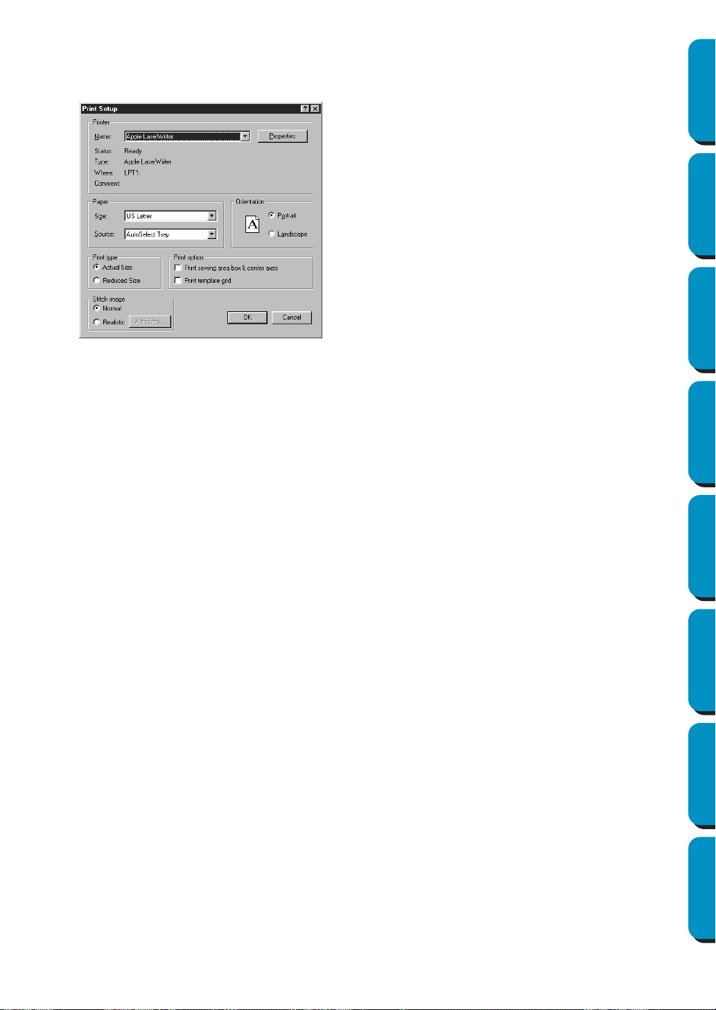
162
Contents Before Using Getting Started Design Center Layout & Editing
Programmable
Stitch Creator
Quick Reference Alphabetic Index
Operation:
1 Click File, then Print Setup.
A
Print Setup dialog similar to this will display.
You can choose to print the preview image on one or two pages for one pattern or one hoop position.
The Actual Size will print two pages:
The image in its actual size on the first and the dimensions of the embroidery, the sewing color
order and the needle count on the second page. The file name is printed on both pages.
The Reduced Size will print a reduced illustration of the image and all the above mentioned items
on a single page.
NOTE:
If a Design Page for a multi-position embroidery frame (130
×
300 mm, 300
×
130 mm, 100
×
172
mm, or 172
×
100 mm) is selected, each Print type will print the whole image of Design Page on
the first page.
And in this case, the number of pages depends on your design.
Print sewing area box & center axes
Select Print sewing area box & center axes to print black lines to indicate the sewing area (see
“Select Sewing Area”) and the center axes for the data.
This setting is only available when Actual Size is selected.
Print template grid
Select
Print template grid to print green lines to represent the grid printed on the embroidery sheet
included with the embroidery frame.
NOTE:
The size of the grid that is printed may be slightly different from the grid printed on the embroidery
sheets for some embroidering machines.
If
Stitch Image is set to Normal, the pattern is printed as lines and dots.
If Stitch Image is set to Realistic, the pattern is printed as a realistic image.
NOTE:
To change the settings of a realistic image, click Attributes.
See “Realistic Preview Attribute Setting” for more details.
These attributes are stored separately from the Realistic Preview attributes.
See also: “Realistic Preview Attribute Setting” on page 221
◆ Click Properties to set the printer
properties.
◆ Choose the appropriate Paper
and Orientation settings.
◆ Choose the Print type and Print
Option
of the preview image and
sewing information.
◆ Click OK to confirm the settings.
◆ Click Cancel to exit.
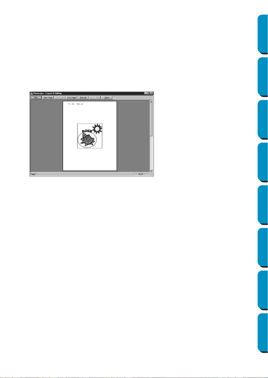
163
Contents Before Using Getting Started Design Center Layout & Editing
Programmable
Stitch Creator
Quick Reference Alphabetic Index
■ Print Preview
Purpose: Allows you to preview the contents of the Design Page and check the sewing color
order, the dimensions and the needle count before printing.
Shortcut key: No shortcut key for this function
Toolbar: No button for this function
Operation:
1 Click File, then Print Preview.
If
Actual Size was selected in the Print Setup dialog, the Layout & Editing window changes to the
following.
2 Enlarge the image either by clicking Zoom In or by clicking directly on the point of the page that you
want to enlarge. Scroll the page as needed to view its hidden parts.
When you reach the limit of the zooming in function, the Zoom In button becomes inactive and the
Zoom Out button becomes active. Click the Zoom Out button or the image to reduce its size again.
One of the zooming function is always active.
3 Click Next Page to display page 2 containing the sewing information (not available if Reduced Size
was selected in the
Print Setup dialog).
This button becomes inactive and the Prev Page button becomes active.
4 Click Prev Page to go back to the display of the embroidery (not available if Reduced Size was
selected in the Print Setup dialog).
This button becomes inactive and the Next Page button becomes active.
5 Click Two Page to display both pages at the same time. The Two Page button is replaced by the One
Page
button.
Click One Page to display one page at a time. The Next Page and Prev Page become inactive.
NOTE:
If you need to view an image in detail, displaying only one page at a time allows you to enlarge it
more.
If you want to check the sewing information for individual objects composing your embroidery, you
can do that by clicking Option – Design Property.
The buttons that are selectable dis-
play in black and the other ones are
grayed.
◆ Click Print to open the Print dialog
and print.
◆ Click Next Page to display the next
page.
◆ Click Prev Page to display the
previous page.
◆ Click Two Page to display both
pages at the same time.
◆ Click Zoom In and Zoom Out to
enlarge and reduce the page.
◆ Click Close to return to the Design
Page.
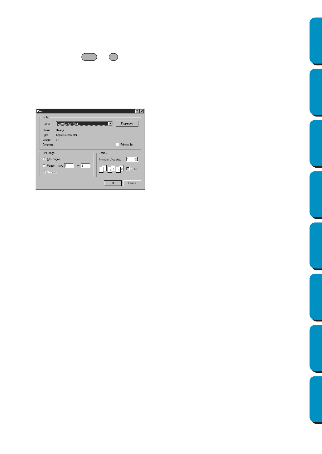
164
Contents Before Using Getting Started Design Center Layout & Editing
Programmable
Stitch Creator
Quick Reference Alphabetic Index
See also: “Print Setup” on page 161, “Print” below and “Design Property” on page 223
■ Print
Purpose: Prints your Design Page and some sewing information.
Shortcut key: +
Toolbar: No button for this function
Operation:
1 Click File, then Print.
A Print dialog similar to this will display.
2 Follow the instructions in the Windows manuals and in the manuals of your printer for the next
operations.
Depending on the
Print Type setting, one or two pages will be printed for one pattern or one hoop
position.
Printing a Design Page for a multi-position embroidery frame (130 × 300 mm, 300
× 130 mm, 100 × 172 mm, or 172 × 100 mm)
If a Design Page for a multi-position embroidery frame is selected, each section of the design is printed
on a separate page.
• If a 130 × 300 mm or 300 × 130 mm Design Page is selected, the design is divided into sections of
130 × 180 mm or 180 × 130 mm and each section is printed on a separate page.
• If a 100 × 172 mm or 172 × 100 mm Design Page is selected, the design is divided into sections of
100 × 100 mm and each section is printed on a separate page.
Printing a Design Page for a multi-position embroidery frame
When Actual Size is selected:
1 Prints the entire Design Page at actual size
(However, for a 130 × 300 mm or 300 × 130 mm Design Page, a reduced image of the Design
Page is printed.)
2 Prints the pattern in the section of the Design Page that would be sewn with the first embroidery
frame installation position
3 Prints the color order for the pattern in the section of the Design Page that would be sewn with the
first embroidery frame installation position
4 Prints the pattern in the section of the Design Page that would be sewn with the second embroi-
dery frame installation position
◆ Make the necessary setting.
◆ Click
OK to print.
◆ Click Cancel to exit.
◆ Click Properties to change the default
settings of the printer.
Ctrl P
165
Contents Before Using Getting Started Design Center Layout & Editing
Programmable
Stitch Creator
Quick Reference Alphabetic Index
5 Prints the color order for the pattern in the section of the Design Page that would be sewn with the
second embroidery frame installation position
:
This continues until all of the sewing data is printed.
When
Reduced Size is selected:
1 Prints the entire Design Page at actual size
(However, for a 130 × 300 mm or 300 × 130 mm Design Page, a reduced image of the Design
Page is printed.)
2 Prints the pattern and its color order for the section of the Design Page that would be sewn with
the first embroidery frame installation position
3 Prints the pattern and its color order for the section of the Design Page that would be sewn with
the second embroidery frame installation position
:
This continues until all of the sewing data is printed.
NOTE:
In addition, when the File – Print Preview command is selected, each section of the pattern is dis-
played as mentioned above.
■ Exit
Purpose: Exits the application.
Shortcut key: +
Toolbar: No button for this function
Operation:
1 Click File, then Exit.
If the current Design Page is not edited, the application closes immediately.
2 If the current Design Page is edited, you will be asked whether you want to save the changes. See
“Open” on page 150.
See also: “Save” and “Save As” on page 156
Alt F4
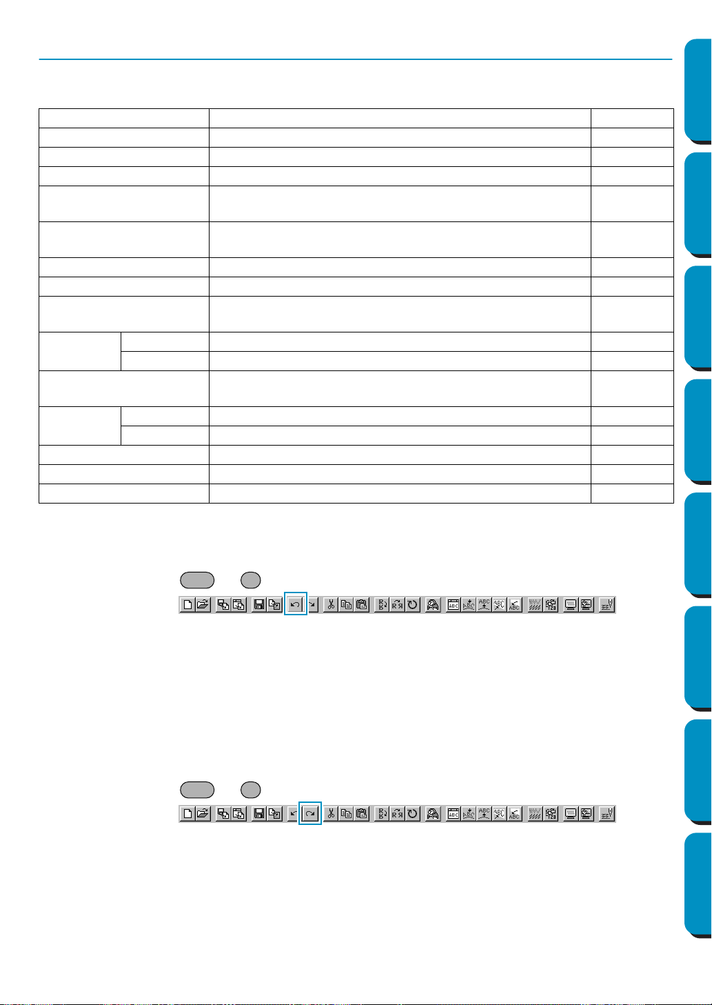
166
Contents Before Using Getting Started Design Center Layout & Editing
Programmable
Stitch Creator
Quick Reference Alphabetic Index
Edit Menu
The functions of the Edit menu perform simple actions on selected patterns, such as cutting and pasting.
■ Undo
Purpose: Undoes the last operation.
Shortcut key: +
Toolbar:
Operation:
1 Click Edit, then Undo.
The last operation is automatically undone. For example, if you have mistakenly deleted an pat-
tern, this function will make it reappear.
See also: “Redo” below
■ Redo
Purpose: Cancels the effect of the last Undo.
Shortcut key: +
Toolbar:
Operation:
1 Click Edit, then Redo.
The effect of the last
Undo is cancelled. For example, you have used Undo just after drawing a cir-
cle. Undo deleted the circle. Using Redo will make the circle reappear.
See also: “Undo” above
Undo Undoes the last operation. page 166
Redo Cancels the effect of the last Undo. page 166
Group Turns several selected objects into one object. page 167
Ungroup Cancels the grouping for grouped objects. page 167
Cut
Removes the selected pattern(s) from the screen while sav-
ing a copy in the clipboard.
page 167
Copy
Saves the selected pattern(s) in the clipboard without
removing them from the screen.
page 168
Duplicate Makes a copy of the selected pattern(s). page 168
Paste Pastes the contents of the clipboard on the screen. page 168
Delete
Removes the selected pattern(s) from the screen without
saving them in the clipboard.
page 168
Mirror
Horizontal Flips the selected pattern(s) up/down. page 169
Vertical Flips the selected pattern(s) left/right. page 169
Rotate
Allows you to manually rotate the selected pattern(s) by an
arbitrary angle.
page 170
Numerical
Setting
Size Resizes the selected pattern numerically. page 171
Rotate Rotates the selected pattern numerically. page 172
Center Moves the selected object to the center of Design Page. page 172
Align Aligns the selected patterns as indicated. page 173
Select All Selects all the patterns. page 174
Ctrl Z
Ctrl A
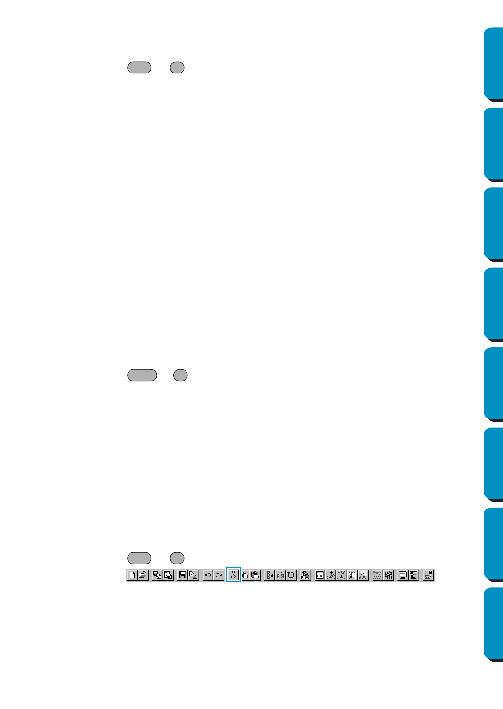
167
Contents Before Using Getting Started Design Center Layout & Editing
Programmable
Stitch Creator
Quick Reference Alphabetic Index
■ Group
Purpose: Turns several selected objects into one object.
Shortcut key: +
Toolbar: No button for this function
Operation:
1 Select several objects.
2 Click Edit then Group.
The selected objects will become one object.
You can treat the objects as one object for any further editing functions.
NOTE:
When this function is operated, the sewing order for the selected objects will change. The grouped
objects will be moved to the sewing position of the last object in the group, and will be sewn in
order in that position. The sewing order of the grouped objects can not be changed, nor can
another object be inserted in the sewing order of the grouped objects. If you want to change the
sewing order in those ways, cancel the grouping.
NOTE:
• If you select either a path, or text fit to a path, both will be included in the grouping.
• When selecting an object set as part of a hole sewing pattern, the entire hole sewing pattern will
be included in the grouping.
See also: “Ungroup” below
■ Ungroup
Purpose: Cancels the grouping for grouped objects.
Shortcut key: +
Toolbar: No button for this function
Operation:
1 Select a grouped object.
2 Click Edit then Ungroup.
The grouping of the selected object is cancelled.
After completing this operation, you can carry out editing operations on each object individually.
See also: “Group” above
■ Cut
Purpose: Removes the selected pattern(s) from the screen while saving a copy in the clip-
board.
Shortcut key: +
Toolbar:
Operation:
1 Select one or more patterns.
Ctrl G
Shift G
Ctrl X
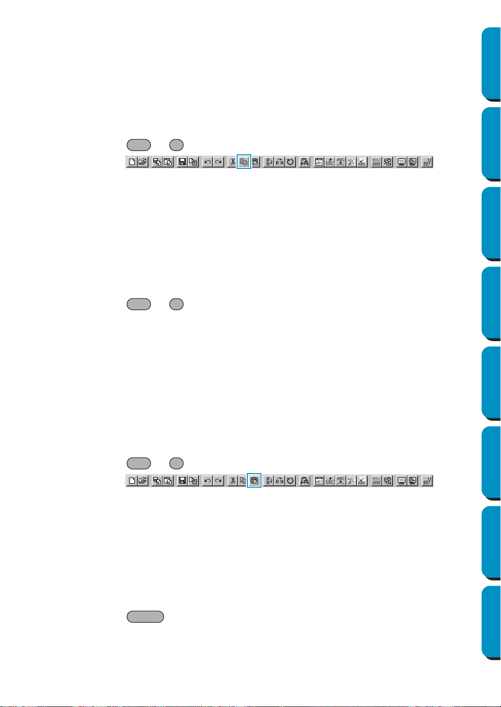
168
Contents Before Using Getting Started Design Center Layout & Editing
Programmable
Stitch Creator
Quick Reference Alphabetic Index
2 Click Edit, then Cut.
The selected patterns disappear. Since they are saved in the clipboard, you can paste them back
using
Edit – Paste.
See also: “Copy”, “Paste” and “Delete” below
■ Copy
Purpose: Saves the selected pattern(s) in the clipboard without removing them from the
screen.
Shortcut key: +
Toolbar:
Operation:
1 Select one or more patterns.
2 Click Edit, then Copy.
The patterns are copied into the clipboard and are ready to be pasted.
See also: “Cut” on page 167, “Duplicate” and “Paste” below
■ Duplicate
Purpose: Makes a copy of the selected pattern(s).
Shortcut key: +
Toolbar: No button for this function
Operation:
1 Select one or more patterns.
2 Click Edit, then Duplicate.
A copy of the patterns appears on the screen.
See also: “Copy” above and “Paste” below
■ Paste
Purpose: Pastes the contents of the clipboard on the screen.
Shortcut key: +
Toolbar:
Operation:
1 Click Edit, then Paste.
The patterns saved in the clipboard (using Cut or Copy) are pasted on the screen.
See also: “Cut” on page 167, “Copy” and “Duplicate” above
■ Delete
Purpose: Removes the selected pattern(s) from the screen without saving them in the clip-
board.
Shortcut key:
Toolbar: No button for this function
Ctrl C
Ctrl D
Ctrl V
Delete
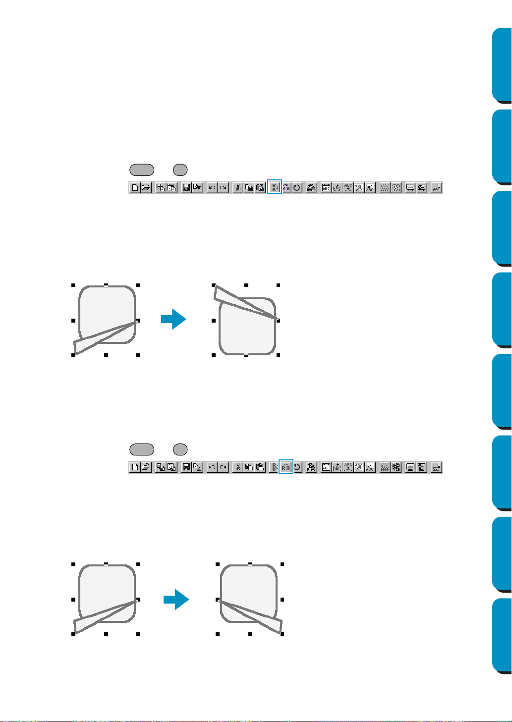
169
Contents Before Using Getting Started Design Center Layout & Editing
Programmable
Stitch Creator
Quick Reference Alphabetic Index
Operation:
1 Select one or more patterns.
2 Click Edit, then Delete.
The selected pattern(s) are removed from the screen. Since they are not saved in the clipboard,
the only way to make them reappear is to use
Edit – Undo.
See also: “Undo” on page 166, “Cut” on page 167
■ Mirror – Horizontal
Purpose: Flips the selected pattern(s) up/down.
Shortcut key: +
Toolbar:
Operation:
1 Select one or more patterns.
2 Click Edit, then Mirror, then Horizontal.
The selected pattern(s) are replaced by their horizontal mirror image (top and bottom inverted).
Two successive applications of this function restores the original image.
Note that some patterns installed from a card cannot be flipped.
See also: “Mirror – Vertical” below, “Rotate” on page 170
■ Mirror – Vertical
Purpose: Flips the selected pattern(s) left/right.
Shortcut key: +
Toolbar:
Operation:
1 Select one or more patterns.
2 Click Edit, then Mirror, then Vertical.
The selected pattern(s) are replaced by their vertical mirror image (left and right inverted).
Two successive applications of this function restores the original image.
Note that some patterns installed from a card cannot be flipped.
See also: “Mirror – Horizontal” above, “Rotate” on page 170
Ctrl H
Ctrl J
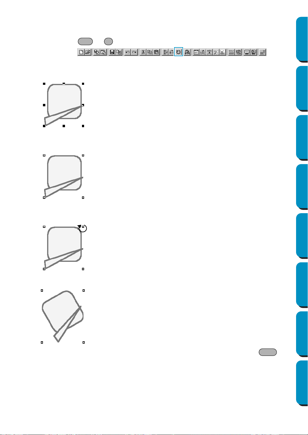
170
Contents Before Using Getting Started Design Center Layout & Editing
Programmable
Stitch Creator
Quick Reference Alphabetic Index
■ Rotate
Purpose: Allows you to manually rotate the selected pattern(s) by an arbitrary angle.
Shortcut key: +
Toolbar:
Operation:
1 Select one or more patterns.
2 Click Edit, then Rotate.
The shape of the handles changes.
3 Move the cursor to one of the handles.
The shape of the cursor changes.
4 Drag the handle to rotate the pattern the desired angle and release the mouse button.
A simple dragging of the mouse will rotate the pattern by 1˚ increments. Pressing the key
will rotate it by 15˚ increments.
See also: “Mirror – Horizontal” and “Mirror – Vertical” on page 169
Ctrl Y
Shift

171
Contents Before Using Getting Started Design Center Layout & Editing
Programmable
Stitch Creator
Quick Reference Alphabetic Index
■ Numerical Setting-Size
Purpose: Resizes the selected pattern numerically.
Shortcut key: No shortcut key for this function
Toolbar: No button for this function
Operation:
1 Select one or more patterns.
2 Click Edit, then Numerical Setting, then Size.
The
Size dialog appears.
◆ To change the width and height proportion-
ally, check aspect.
◆ Select the units (% or mm/inch) for the
width and height.
◆ Either typing in a value or clicking the
arrows to select the desired value can
enter the width and height.
Select 100% to leave the pattern
unchanged.
If aspect is selected, changing one dimen-
sion automatically changes the other so
the proportion of the width and height
remains unchanged.
The specified size is for the region. If the
pattern has a line, the size of the entire pat-
tern can be checked under Region + Line
Size
at the bottom of the dialog.
◆ Click OK to confirm.
◆ Click
Preview to view the pattern at the new
size in the Design Page.
◆ Click
Cancel to exit without making any
changes.
Region (without line)
Region + line
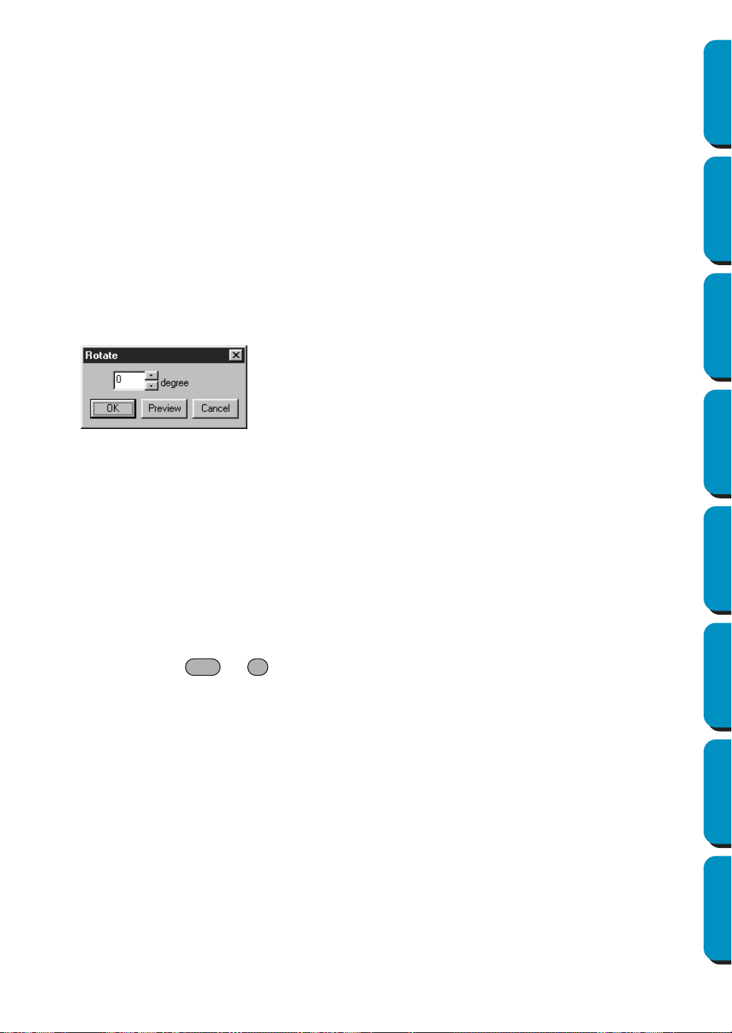
172
Contents Before Using Getting Started Design Center Layout & Editing
Programmable
Stitch Creator
Quick Reference Alphabetic Index
NOTE:
The maximum value that can be entered is the largest value that will not allow the pattern to
exceed the size of the Design Page.
The minimum value is 1 mm (0.04 inch).
See also: “Select System Unit” on page 229
■ Numerical Setting-Rotate
Purpose: Rotates the selected pattern numerically.
Shortcut key: No shortcut key for this function
Toolbar: No button for this function
Operation:
1 Select one or more patterns.
2 Click Edit, then Numerical Setting, then Rotate.
The Rotate dialog appears.
NOTE:
The range of values that can be entered is between 0 and 359 degrees, in 1degree increments.
■ Center
Purpose: Moves the selected object to the center of Design Page.
Shortcut key: +
Toolbar: No button for this function
Operation:
1 Select one or more objects.
2 Click Edit, then Center.
The entire selected object moves to the center of Design Page.
NOTE:
For Letters Fit to a Path
If you select either the letters or the path only, the selected object will be moved to the center of
Design page, but the unselected object will not be moved with it.
For Objects set for Hole Sewing
When selecting an object set as part of a hole sewing pattern, the selected object will be
moved to the center of Design Page, but the unselected objects will not be moved with it.
◆ The desired rotation angle can be entered
by either typing in a value or clicking the
arrows to select the desired value.
Select 0 degree to leave the pattern
unchanged.
◆ Click
OK to confirm.
◆ Click
Preview to view the pattern rotated
the specified angle in the Design Page.
◆ Click Cancel to exit without making any
changes.
Ctrl M
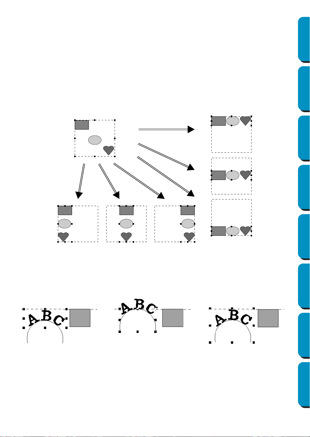
173
Contents Before Using Getting Started Design Center Layout & Editing
Programmable
Stitch Creator
Quick Reference Alphabetic Index
■ Align
Purpose: Aligns the selected patterns as indicated.
Shortcut key: No shortcut key for this function
Toolbar: No button for this function
Operation:
1 Select the patterns which you want to Align.
2 Click Edit, then Align, then Left, Center, Right, Top, Middle, or Bottom, depending on how you wish
to align the patterns.
The selected patterns are aligned as shown below.
3 To choose a different alignment, click Undo and repeat 2.
Text on a path:
Text on a path can be aligned by selecting other objects on the design page as well as the text, the
path, or both the text and the path. Each selected pattern is aligned on its outline. In order to align
with object(s) on the design page all the object(s) must be selected with text and/or path.
NOTE:
Refer to index for related topics, if necessary.
Objects set for hole sewing:
If just the inside of a pattern is selected, the pattern is aligned on the outline of the inside area. If the
outside of the pattern is also selected, the pattern is aligned on the outline of the outside area. In
order to align with object(s) on the design page all the object(s) must be selected.
Bottom
RightCenterLeft
Middle
Top
1. Text is selected 2. Path is selected 3. Both the text and path
are selected
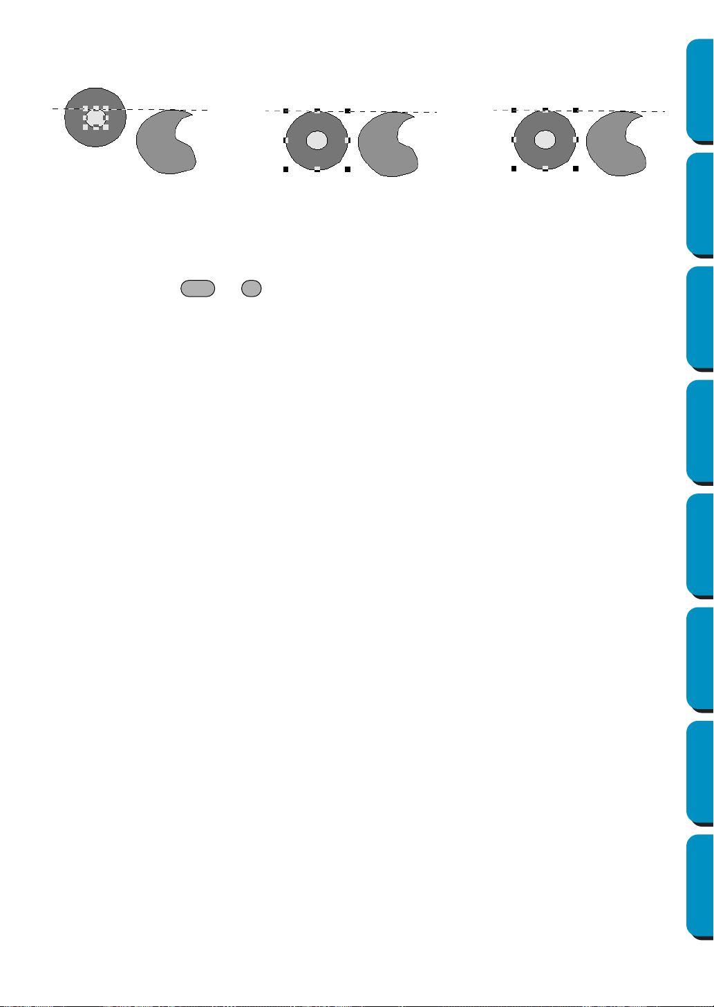
174
Contents Before Using Getting Started Design Center Layout & Editing
Programmable
Stitch Creator
Quick Reference Alphabetic Index
NOTE:
Refer to index for related topics, if necessary.
■ Select All
Purpose: Selects all the patterns.
Shortcut key: +
Toolbar: No button for this function
Operation:
1 Make sure that the cursor is in Selection mode.
2 Click Edit, then Select All.
1. Inside area is
selected
2. Outside area is
selected
3. Both the inside and
outside areas are selected
Ctrl E
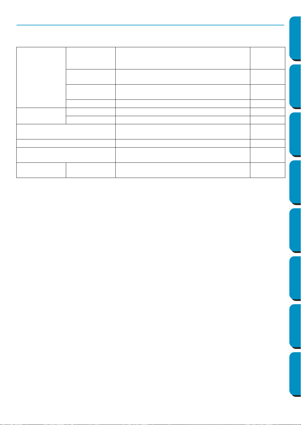
175
Contents Before Using Getting Started Design Center Layout & Editing
Programmable
Stitch Creator
Quick Reference Alphabetic Index
Image Menu
The Image menu contains commands for importing and exporting image data and creating embroidery
data from image data.
Input
from File
Imports image data from an existing file so that it
can be used as a guide for creating embroidery
data
page 176
from TWAIN
device
Operates a TWAIN standardized scanner or other
device to import an image.
page 176
from Portrait
Combine images of facial features that are built in
to the program to create an original portrait.
page 177
from Clipboard Import image data from the clipboard. page 178
Output
to File Saves the image data as a file. page 179
to Clipboard Copies the image data onto the clipboard. page 179
Select TWAIN device
Selects which TWAIN device installed in the com-
puter to use.
page 179
Modify Adjusts the size and position of the image data. page 180
Image to Stitch Wizard
Gives step-by-step instruction for creating
embroidery data from image data.
page 181
Display Image On, Faded, Off
Turns on or off the template image or displays it
faded.
page 196
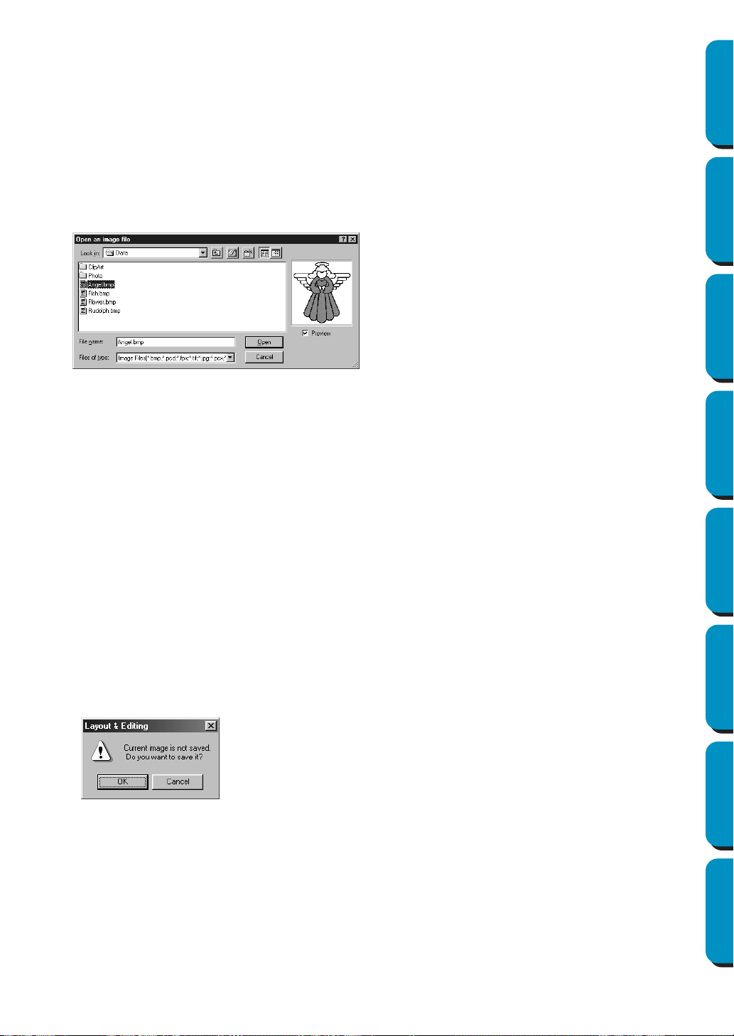
176
Contents Before Using Getting Started Design Center Layout & Editing
Programmable
Stitch Creator
Quick Reference Alphabetic Index
■ Input – from File
Purpose: Imports image data from an existing file so that it can be used as a guide for creat-
ing embroidery data
Shortcut key: No shortcut key for this function
Toolbar: No button for this function
Operation:
1 Click Image, then Input, then from File.
A dialog similar to the one shown below appears.
NOTE:
For pcd and fpx files that are saved on many pages, only the first page can be opened. Tif files that
have used LZW compression can not be opened.
NOTE:
If image data that has previously been edited is selected, the image data is corrected to the previ-
ously edited position and size, then opened.
2 Your Design Page will display the image.
If the current image is not saved, you will be asked whether you want to save it.
■ Input – from TWAIN device
Purpose: Operates a TWAIN standardized scanner or other device to import an image.
Shortcut key: No shortcut key for this function
Toolbar: No button for this function
◆ Select the drive, the folder and the file
name.
• If the Preview check box is checked, the
contents of the selected file displays in
the Preview window.
◆ Click
Open to open the file.
• Double-clicking the file name will also
open the file and close the dialog.
◆ Click
Cancel if you want to exit the func-
tion.
• The file extension must be one of the fol-
lowing: Windows BMP (*.bmp), Exif (*.tif,
*.jpg), ZSoftPCX (*.pcx), Windows Meta
File (*.wmf), Portable Network Graphics
(*.png), Encapsulated PostScript (*.eps),
Kodak PhotoCD (*.pcd), FlashPix (*.fpx),
JPEG2000 (*.j2k).
◆ Click
OK to save the image.
◆ Click Cancel to finish without saving the image.
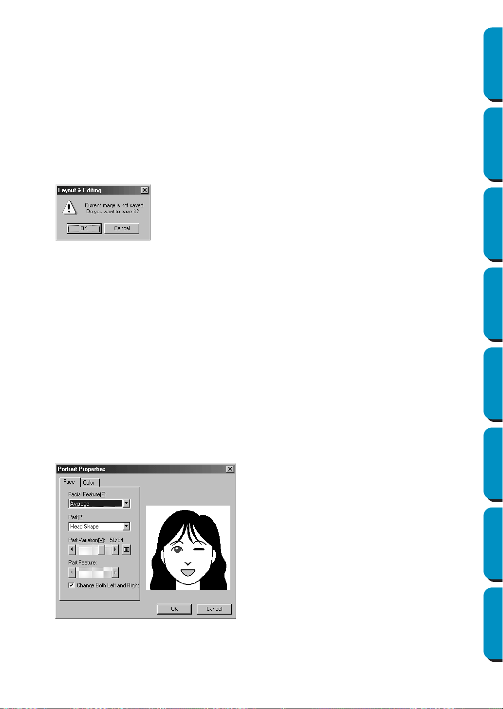
177
Contents Before Using Getting Started Design Center Layout & Editing
Programmable
Stitch Creator
Quick Reference Alphabetic Index
Operation:
1 Check that the scanner or other device is correctly connected.
2 Click Image, then Input, then from TWAIN device.
The driver interface set in the
Select TWAIN device dialog is displayed.
Operate that interface, make the settings for importing an image, and import the image.
NOTE:
For information on using the interface, see the help manual for that interface, or contact the manu-
facturers of the interface.
3 When the image transfer between the scanner (or other device) and the driver is complete, the
imported image will be pasted in Design Page.
If the current image is not saved, you will be asked whether you want to save it.
NOTE:
TWAIN is an application interface (API) standardization for software controlling scanners, etc.
Also, the software itself is called TWAIN.
This software supports TWAIN standardized devices, so you can control the scanner and import
the image directly.
Before using this function, you must go to the
Select TWAIN device dialog to select a TWAIN device.
■ Input – from Portrait
Purpose: Combine images of facial features that are built in to the program to create an
original portrait.
Shortcut key: No shortcut key for this function
Toolbar: No button for this function
Operation:
1 Click Image, then Input, then from Portrait.
A dialog similar to the one shown below appears.
◆ Click
OK to save the image.
◆ Click Cancel to finish without saving the image.
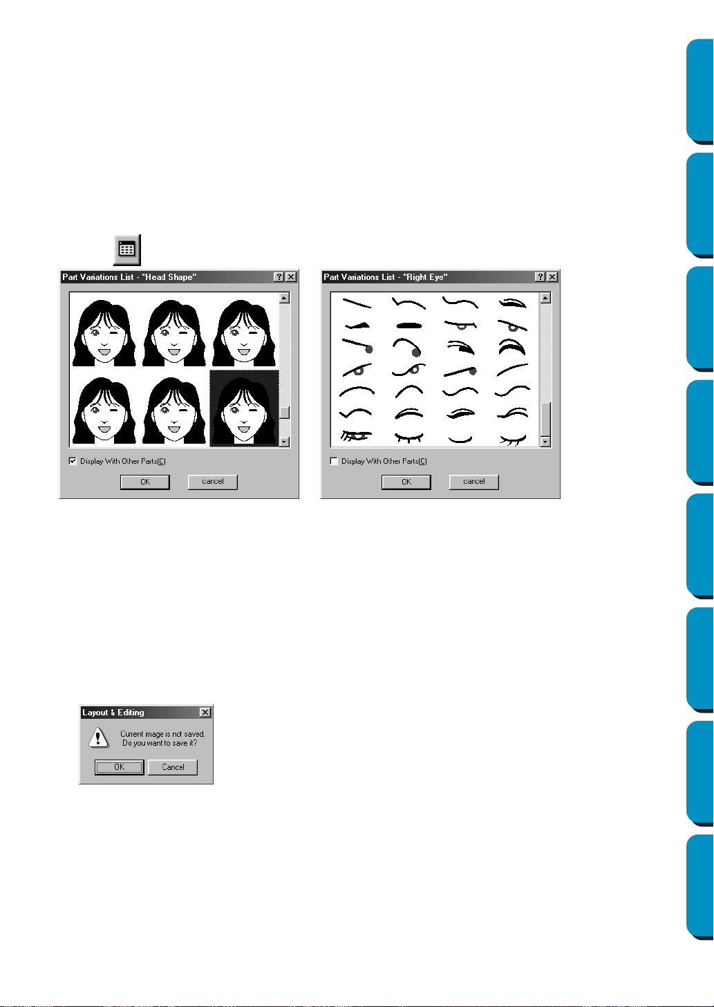
178
Contents Before Using Getting Started Design Center Layout & Editing
Programmable
Stitch Creator
Quick Reference Alphabetic Index
2 While checking the sample image on the right side of the dialog, select the various facial features.
◆ Select the overall contour (appearance) of the portrait from the Facial Feature list.
Select from narrow, wide, child-like, etc.
◆ Select a part of the portrait from the Part list.
The part of the portrait to be changed can also be selected by clicking it in the sample image.
◆ Drag the Part Variation slider to select the part variation. The selected part variation is shown in the
sample image.
Select the Change Both Left and Right check box to change both sides of a part, such as the eyes or
ears.
◆ Click to display all variations of the selected part.
If the Display With Other Parts check box is selected, images of all parts combined are displayed. If
the check box is not selected, only the variations of the selected part are displayed.
Select a part from the list, and then click OK.
◆ Drag the Part Feature slider to change the part feature.
Select from making the part standard size, slightly larger, slightly smaller, wider or taller.
◆ Click the Color tab to change the color of the part.
3 After the portrait is created, click OK.
The portrait image appears in Design Page.
If the current image is not saved, you will be asked whether you want to save it.
■ Input – from Clipboard
Purpose: Import image data from the clipboard.
Shortcut key: No shortcut key for this function
Toolbar: No button for this function
Operation:
◆ Click OK to save the image.
◆ Click Cancel to finish without saving the image.
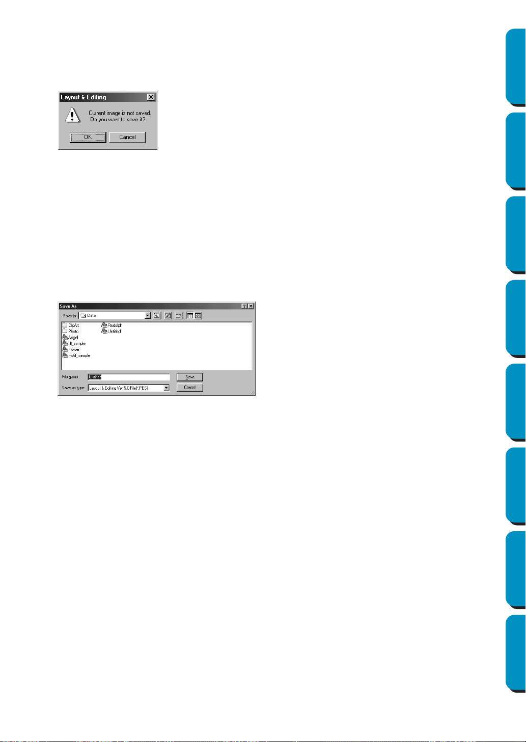
179
Contents Before Using Getting Started Design Center Layout & Editing
Programmable
Stitch Creator
Quick Reference Alphabetic Index
1 Click Image, then Input, then from Clipboard. (This can only be done when there is image data on
the clipboard.)
2 Your Design Page will display the image.
If the current image is not saved, you will be asked whether you want to save it.
■ Output – to File
Purpose: Saves the image data as a file.
Shortcut key: No shortcut key for this function
Toolbar: No button for this function
Operation:
1 Click Image, then Output, then to File.
A dialog similar to the one shown below appears.
■ Output – to Clipboard
Purpose: Copies the image data onto the clipboard.
Shortcut key: No shortcut key for this function
Toolbar: No button for this function
Operation:
1 Click Image, then Output, then to Clipboard.
The image data in the Design Page is copied onto the clipboard.
■ Select TWAIN device
Purpose: Selects which TWAIN device installed in the computer to use.
Shortcut key: No shortcut key for this function
Toolbar: No button for this function
◆ Click OK to save the image.
◆ Click Cancel to finish without saving the image.
◆ Select the drive, the folder and the format
in which you wish to save the image data.
◆ Type the file name.
• The correct extension is automatically
set.
• The image data can be saved in any of
the following formats: Windows BMP
(*.bmp), Exif (*.jpg).
◆ Click Save to save the data.
◆ Click Cancel to exit the function.
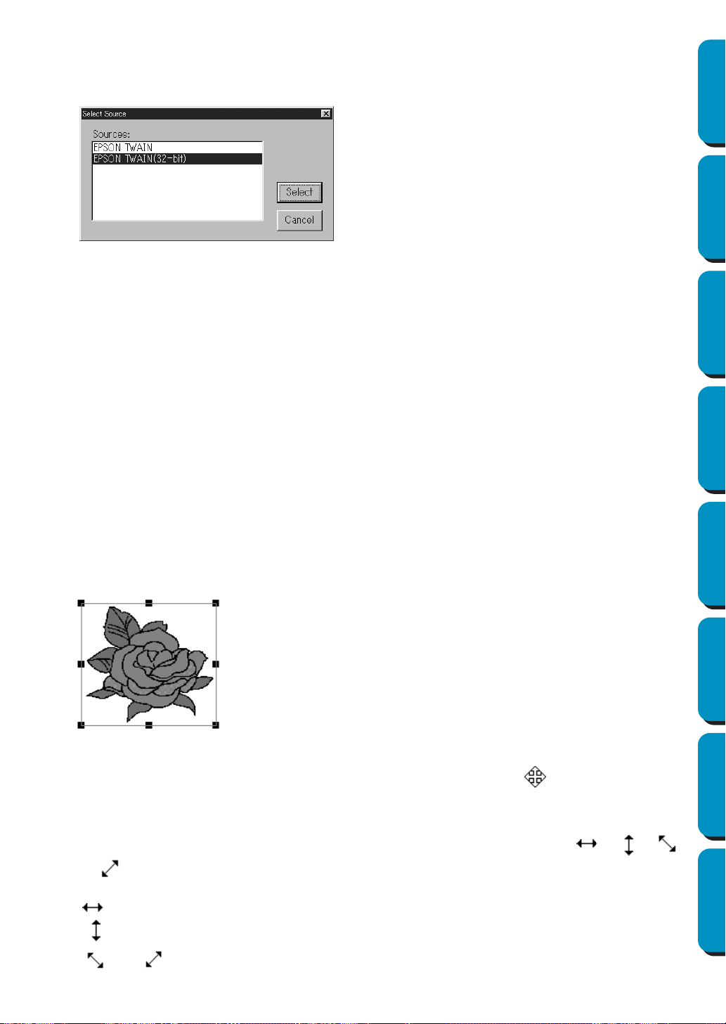
180
Contents Before Using Getting Started Design Center Layout & Editing
Programmable
Stitch Creator
Quick Reference Alphabetic Index
Operation:
1 Click Image, then Select TWAIN device.
A dialog similar to this will display.
2 From the devices in the display, select which device to use and highlight that device.
◆ Click Select to choose the selected device and close the dialog.
◆ Click
Cancel to ignore the operation done to change the device and close the dialog.
NOTE:
If there is no TWAIN device installed, there will be no names displayed on the Sources list.
Use this function after installing the driver software for the TWAIN device you want to use.
■ Modify
Purpose: Adjusts the size and position of the image data.
Shortcut key: No shortcut key for this function
Toolbar: No button for this function
Operation:
1 Click Image, then Modify.
The image to be edited will appear surrounded with a red line and handles.
In addition, the size of the image data is displayed in the status bar.
Moving an image:
Move the cursor over an image. The shape of the cursor will change to .
Drag the image to the desired location.
Scaling an image:
Move the cursor over one of the handles. The shape of the cursor will change to , ,
or , depending on the handle the cursor is on.
Drag the handle in the direction of the arrow to scale the image.
is for scaling the width.
is for scaling the height.
and are for scaling both dimensions at the same time.
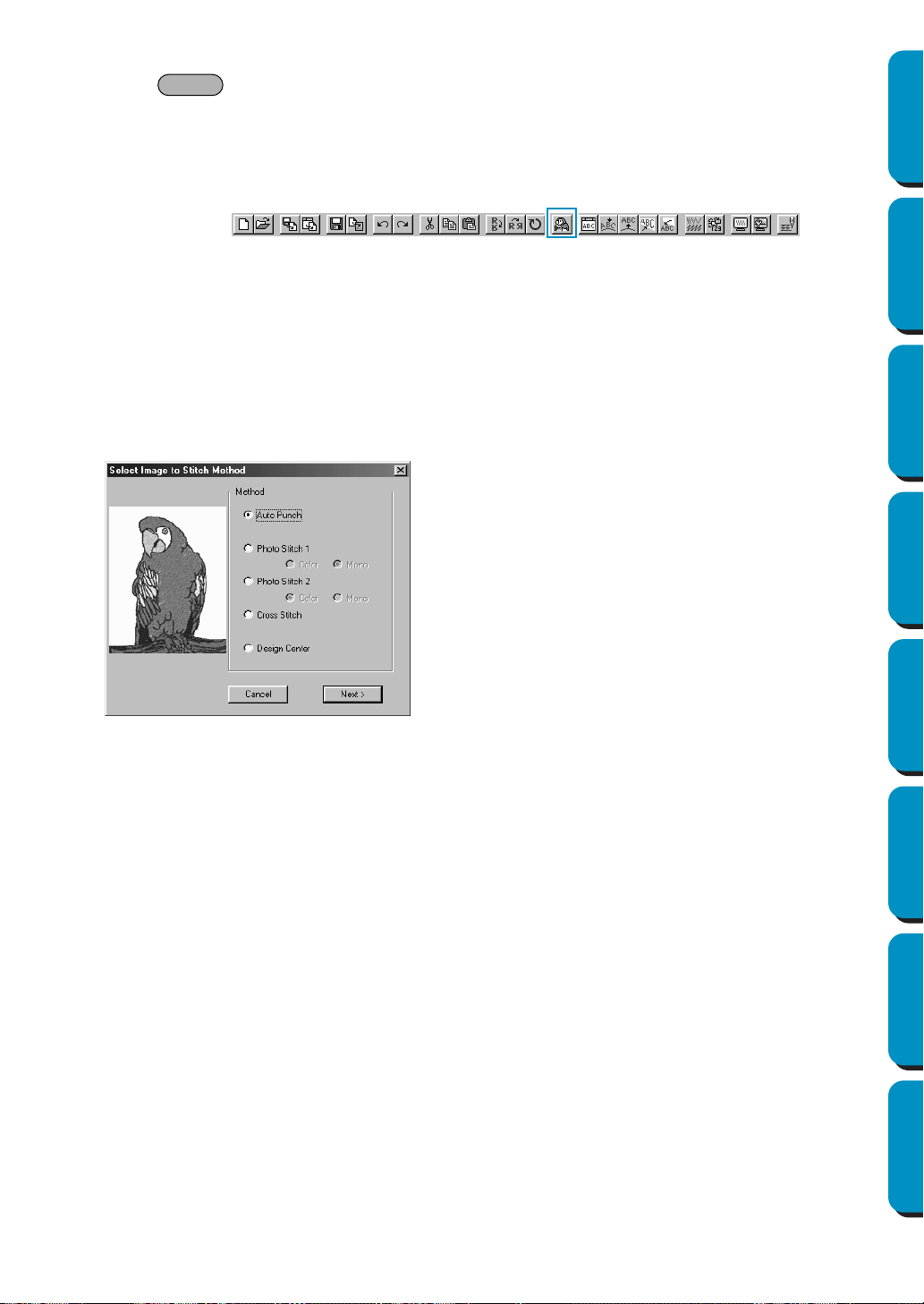
181
Contents Before Using Getting Started Design Center Layout & Editing
Programmable
Stitch Creator
Quick Reference Alphabetic Index
Deleting an image:
Press . The image will be deleted from the Design Page.
■ Image to Stitch Wizard
Purpose: Gives step-by-step instruction for creating embroidery data from image data.
Shortcut key: No shortcut key for this function
Toolbar:
Operation:
1 Use one of the commands on the Input sub-menu of the Image menu to prepare the image data
that will be used to create the embroidery data.
2 Click Image, then Modify, and then re-size and re-position the image data for creating the embroi-
dery data.
3 Click Image, then Image to Stitch Wizard.
The following dialog will appear. (If there is no image in the Design Page, the dialog appears after
an image is imported from a file.
)
◆ Select Auto Punch to automatically
extract the image boundaries in order
to create the embroidery data.
◆ Select Photo Stitch 1 to automatically
create realistic photo embroidery. This
can be set to color or black and white.
◆ Select
Photo Stitch 2 to automatically
create realistic photo embroidery in 4
colors or 1 color.
◆ Select Cross Stitch to create cross-
stitch.
◆ Select
Design Center to run Design
Center with the Design Page Image.
◆ Select the type of embroidery that you
wish to create, and then click Next.
◆ Click
Cancel to quit the operation.
Delete
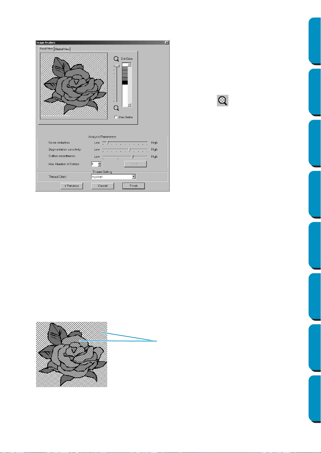
182
Contents Before Using Getting Started Design Center Layout & Editing
Programmable
Stitch Creator
Quick Reference Alphabetic Index
If Auto Punch is selected:
1
After the image characteristics are analyzed, a dialog similar to the one shown below appears.
2 Select the areas that are to be sewn.
In the image on the
Result View tab, areas not set to be sewn are shown filled with a crosshatch
pattern.
Click in the areas to specify whether or not they will be sewn.
◆ Click the
Result View tab to display the
resulting analyzed image. The embroi-
dery data will be created with this
image.
◆ Click the
Original View tab to display the
original image.
◆ Drag the slider to adjust the zoom
ratio that the image is displayed in.
◆ Select the Show Outline check box to
display the outline extracted from the
analyzed image.
◆ Select the desired image-analyzing set-
tings under Analysis Parameters.
Noise reduction: Sets the level of noise
that is removed from the image.
Segmentation sensitivity: Sets the
smoothness of the extracted outline.
Outline smoothness: Sets the smooth-
ness of the extracted outline.
Max. Number of colors: Sets the num-
ber of colors used.
After the necessary settings are
selected, click Retry to re-analyze the
image. If Retry is not clicked, the new
settings are not applied.
Thread Chart: Selects the thread chart
for selecting the thread color. The most
appropriate thread color from the
selected thread chart is selected. A
user thread chart can also be selected.
These areas will not be sewn
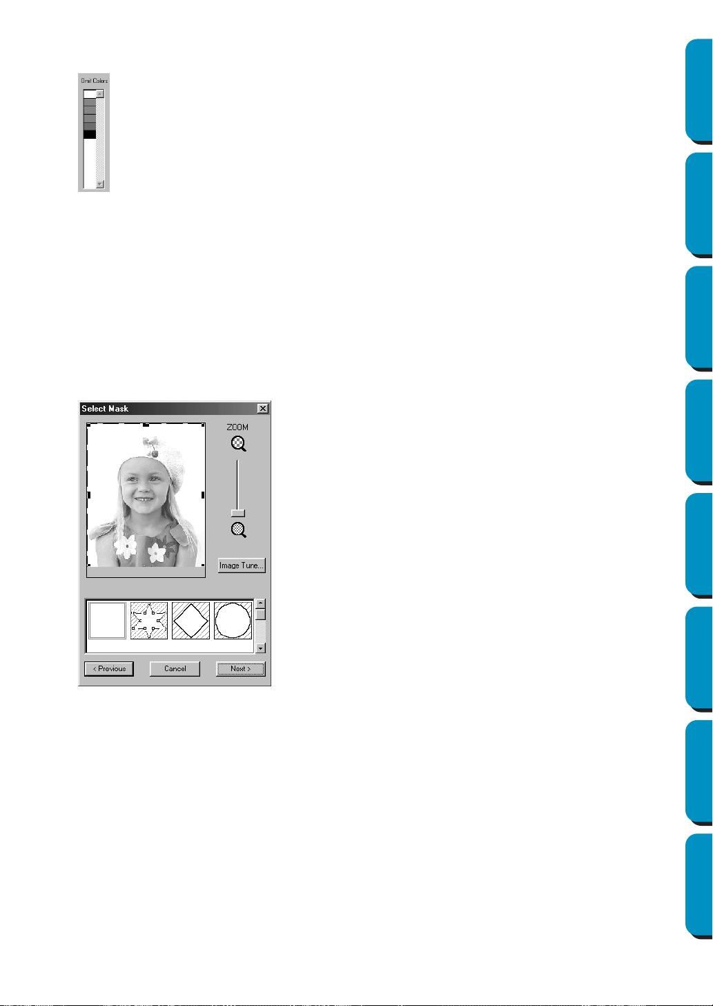
183
Contents Before Using Getting Started Design Center Layout & Editing
Programmable
Stitch Creator
Quick Reference Alphabetic Index
In addition, whether all areas in certain colors will or will not be sewn can be specified in the Omit
Colors list in the upper-right corner of the dialog.
Colors that are crossed out are set to not be sewn.
Click on a color to specify whether or not it will be sewn.
3 After the necessary settings are selected, click Finish.
Embroidery data is created from the outline of the analyzed data, the appropriate thread color and
stitch settings are applied, and then the data is pasted into the Design Page.
The stitch settings of the created embroidery data can later be changed in the same way as the
settings for other shape objects are.
If Photo Stitch 1 (Color) is selected:
1
A Select Mask dialog similar to the one shown below appears.
In this dialog, set the boundaries of the Photo Stitch and make adjustments to the image data.
◆ Click
Image Tune to open the Image
Tune dialog, where you can edit the
image (see below).
◆ Click
Next to display the next dialog.
◆ Click Cancel to close this dialog.
◆ Click
Previous to return to the previous
dialog.
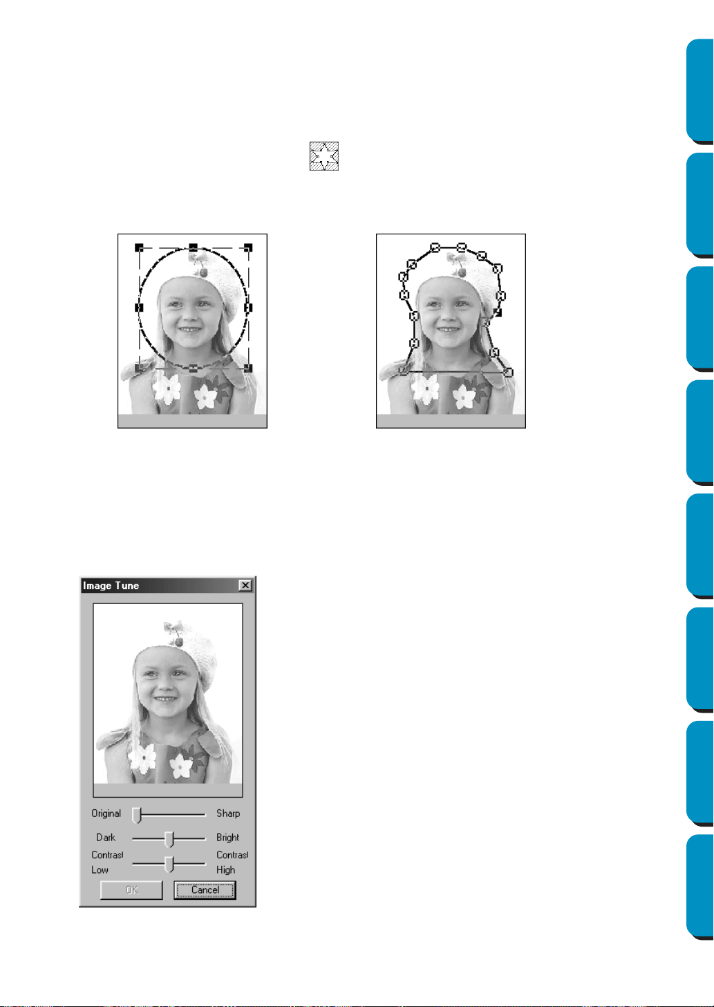
184
Contents Before Using Getting Started Design Center Layout & Editing
Programmable
Stitch Creator
Quick Reference Alphabetic Index
◆ Use the ZOOM slider to zoom in and out on the image, as necessary.
◆ In the Mask Type section in the bottom of the dialog, select the trimming shape you want to use
for the mask, and edit the mask in the shape you want to use. When the dialog opens, the
square mask is selected.
Change the size of the mask by dragging the handles on the outside of the mask.
If you select the Arbitrary Shape Mask , the first display shows white square handles in the four
corners of the square mask.
You can move points, enter points, delete points, or edit this square mask however you like in the
Point Edit mode.
(Pattern edited with the round mask) (Pattern edited with the arbitrary shape mask)
NOTE:
The mask size can be set in the range from 64
×
64 dots to the size of the image data.
[Emphasizing the Outline]
In the Select Mask dialog above, click
Image Tune. An Image Tune dialog similar to the one shown
below appears. You can make the image brighter or darker (clearer or less sharp).
◆ The image window displays the image
resulting from the current operations.
◆ Use
Original – Sharp to adjust the
sharpness of the image’s outlines. A
setting more towards Sharp makes a
more noticeable boundary between
bright and dark areas.
◆ Use Dark – Bright to adjust the bright-
ness of the image.
◆ Use
Contrast Low – High to adjust the
contrast of the image.
◆ Click
OK to show the finished image on
the Design Page and on the Select
Mask dialog, and close this dialog.
◆ Click Cancel to close this dialog.
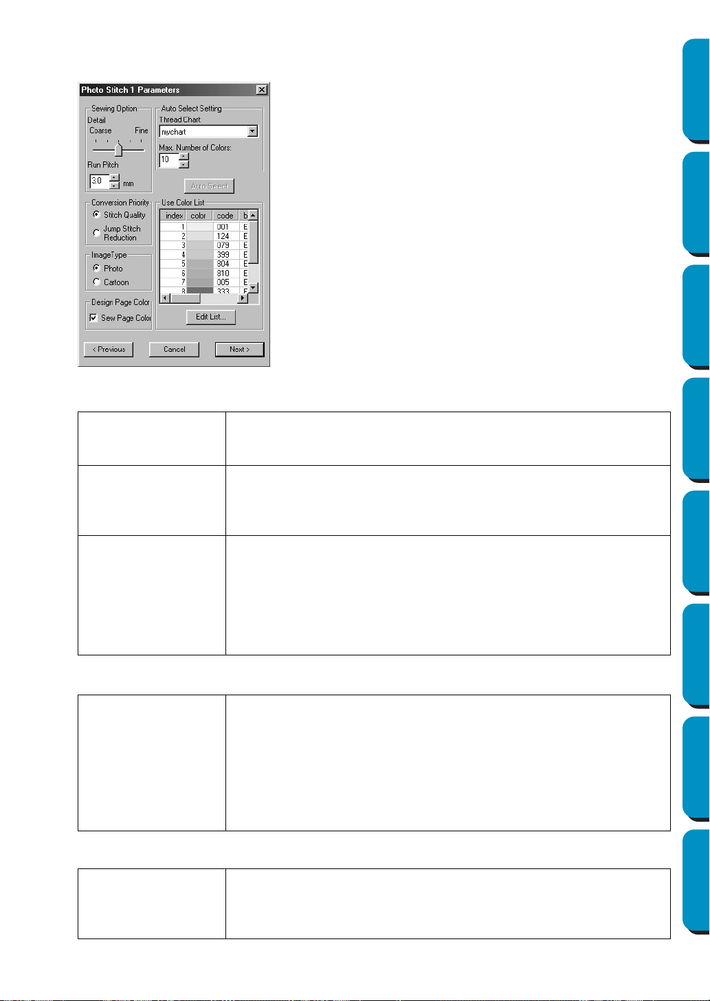
185
Contents Before Using Getting Started Design Center Layout & Editing
Programmable
Stitch Creator
Quick Reference Alphabetic Index
2 In the Select Mask dialog, click Next to display the Photo Stitch Parameters dialog similar to the
one shown below.
Sewing Option:
Image Type:
Design Page Color:
◆ Specify the settings for creating Photo Stitch
data.
◆ Click
Previous to return to the previous dia-
log.
◆ Click Next to apply the settings to the Photo
Stitch data, and display the next dialog.
◆ Click Cancel to close this dialog.
Detail
Specifies how detailed the created embroidery data will be. Selecting a
setting closer to Fine creates more details in the data and increases the
number of stitches.
Run pitch
Sets the sewing pitch. The pattern is created with this setting value as
the minimum length.
Range: 2 - 10 mm (0.08 - 0.39 inch)
Default: 3 mm (0.12 inch)
Conversion Priority
Select what parameter is given priority when converting to embroidery
data.
Stitch Quality: Creates data while giving priority to the stitching quality.
However, many jump stitches will result.
Jump Stitch Reduction: Creates data while giving priority to reducing the
number of jump stitches in order to reduce complications during embroi-
dering. However, the stitching quality will be slightly reduced.
Photo/Cartoon
If Photo is selected, the thread colors will be mixed together, which will
result in a more natural look.
If Cartoon is selected, the thread colors will not be mixed together, which
will result in a more simply colored look.
Select
Photo for image data from a photograph, etc. Select Cartoon for
image data from an illustration, etc.
(If there are less than 16 colors in the image data, the default selection
is Cartoon.)
Sew Page Color
If this item is checked, the data for parts of the pattern that are the same
color as the Design Page will be created. Remove the check from the
item if you will keep the fabric color the same as the Design Page.
The default setting is checked (ON).
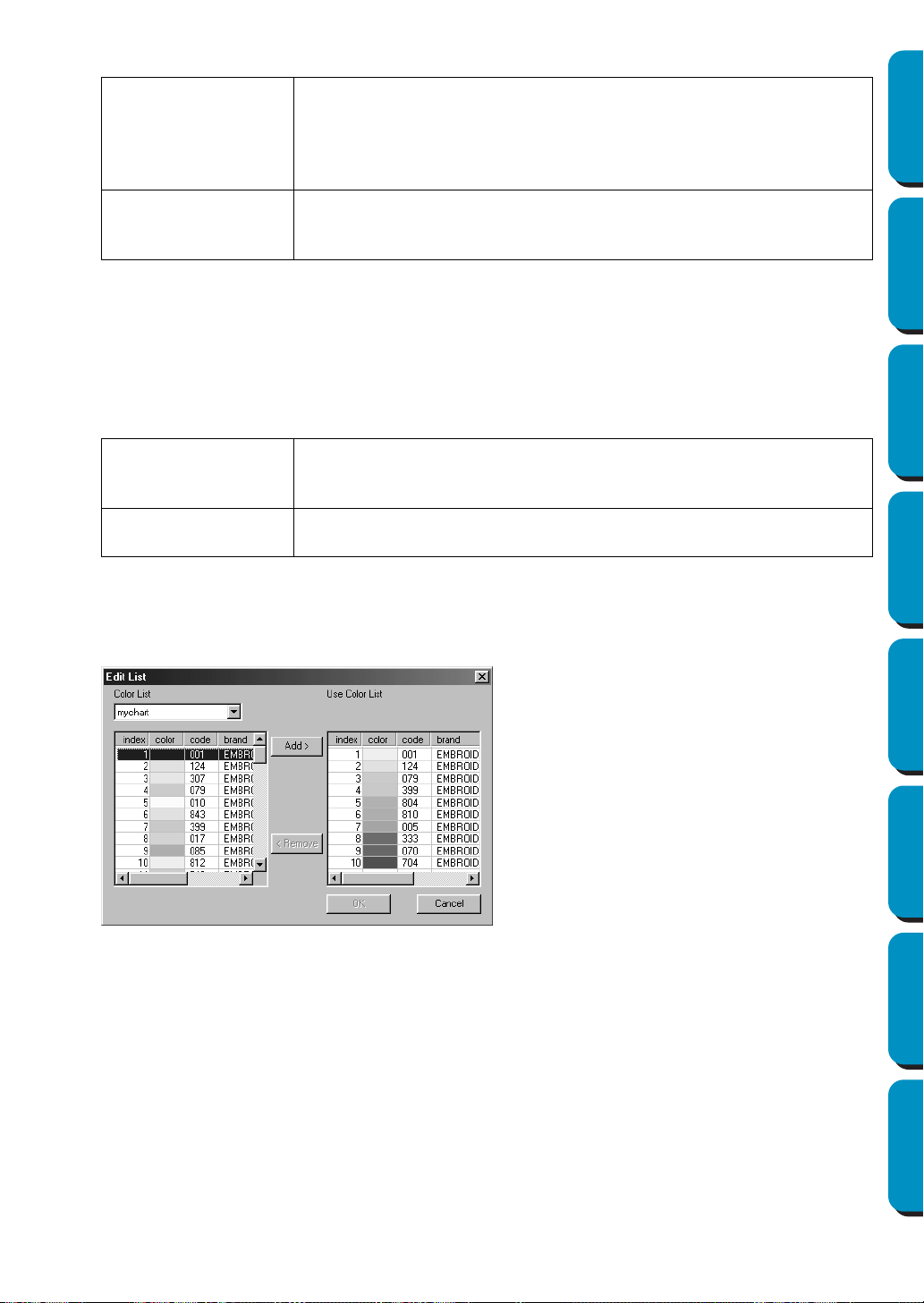
186
Contents Before Using Getting Started Design Center Layout & Editing
Programmable
Stitch Creator
Quick Reference Alphabetic Index
Auto Select Setting:
Auto Select:
Click this button to use the settings specified for Auto Select Setting and automatically select from
the selected thread chart the most appropriate thread colors for creating photo embroidery data.
The selected thread colors appear in the Use Color List mentioned below.
This button can be clicked if the settings for Auto Select Setting have been changed.
Use Color List:
Allows the selected thread colors to be checked and edited.
[Manual Color Selection]
If you click Edit List in the Photo Stitch Parameters dialog above, an Edit List dialog similar to this
will display, and you can manually set the thread colors to be used in the Photo Stitch.
In the System Color List, the thread colors in the selected thread chart are listed in order by the
level of brightness. (Thread colors displayed in the Use Color List are not displayed in the System
Color List.)
Thread Chart
Selects the thread chart for selecting the thread color with the Auto
Select function.
The most appropriate thread color from the selected thread chart is
selected.
A user thread chart can also be selected.
Color Count
Sets the number of colors selected by the
Auto Select function.
Range: 1 - 50
Default: 10
Use Color List
Summary
Thread colors selected for creating the data are displayed in order by
level of brightness. This order is the sewing order. The order can not be
changed. The maximum number of colors is 50.
Edit List
Click this button to open the Edit List dialog, which lets you manually set
the thread colors to be used when creating the data (see below).
◆ Click
Add to add a selected color from
the System Color List to the Use Color
List. If there is no color selected, or if
the Use Color List already has 50 col-
ors, this button can not be used.
◆ Click Remove to delete a selected color
from the Use Color List. If there is no
color selected in the Use Color List, this
button can not be used.
◆ Click OK to apply the edited contents of
the list and close the dialog. The edited
settings will be shown in the Photo
Stitch Parameters dialog. This button
can not be clicked when the Use List
display is empty.
◆ Click Cancel to close the dialog without
applying the edited contents of the list.
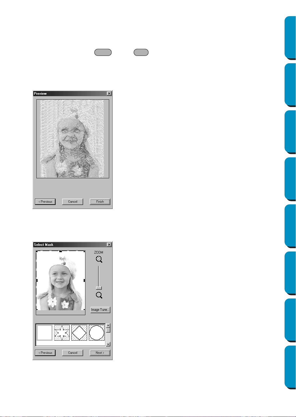
187
Contents Before Using Getting Started Design Center Layout & Editing
Programmable
Stitch Creator
Quick Reference Alphabetic Index
In the Use Color List, thread colors selected for use in the Photo Stitch data are displayed in order
from the brightest. This order is the sewing order. The order can not be changed. The maximum
number of colors that can be added to this list is 50.
From this point, the colors in the lists can be selected by clicking on them, or several colors can be
selected by holding the key or key and clicking on the colors.
3 Click Next in the Photo Stitch Parameters dialog to display a Preview dialog similar to the one
shown below.
The created embroidery data can be previewed in this dialog.
In addition, you can return to previous dialogs in order to change the settings.
If Photo Stitch 1 (Mono) is selected:
1
A Select Mask dialog similar to the one shown below appears.
For details on the settings, refer to 1 of “If Photo Stitch 1 (Color) is selected:”.
In this dialog, set the boundaries of the Photo Stitch and make adjustments to the image data.
◆ Click Previous to return to the previous dia-
log.
◆ Click Finish to paste the created embroidery
data into the Design Page.
◆ Click Cancel to close this dialog.
Shift Ctrl
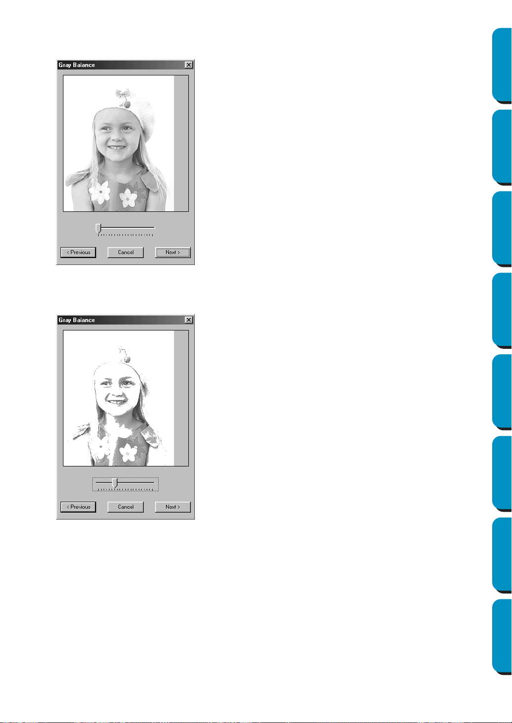
188
Contents Before Using Getting Started Design Center Layout & Editing
Programmable
Stitch Creator
Quick Reference Alphabetic Index
2 In the Select Mask dialog, click Next to display the Gray Balance dialog similar to the one shown
below.
Drag the slider to specify which parts of the image embroidery data will be created for.
Data will be created for any areas remaining in black.
◆ Click
Previous to return to the previous dia-
log.
◆ Click Next to display the next dialog.
◆ Click Cancel to close this dialog.
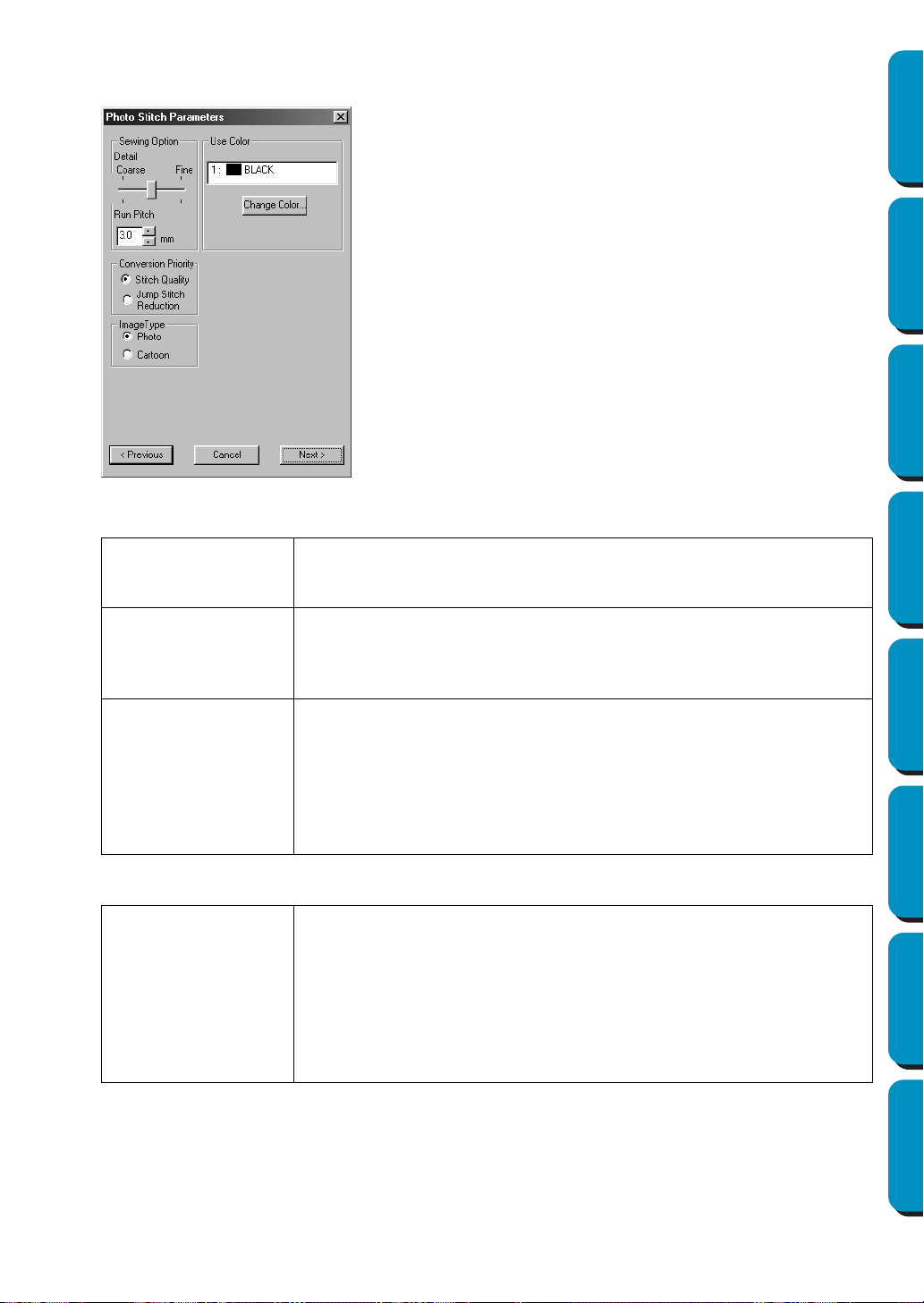
189
Contents Before Using Getting Started Design Center Layout & Editing
Programmable
Stitch Creator
Quick Reference Alphabetic Index
3 In the Gray Balance dialog, click Next to display the Photo Stitch Parameters dialog similar to the
one shown below.
Sewing Option:
Image Type:
Use Color:
Specifies the color of thread used to create the embroidery data.
The default setting is the darkest color in the current thread chart.
◆ Specify the settings for creating Photo Stitch
data.
◆ Click
Previous to return to the previous dia-
log.
◆ Click Next to apply the settings to the Photo
Stitch data, and display the next dialog.
◆ Click Cancel to close this dialog.
Detail
Specifies how detailed the created embroidery data will be. Selecting a
setting closer to
Fine creates more details in the data and increases the
number of stitches.
Run pitch
Sets the sewing pitch. The pattern is created with this setting value as
the minimum length.
Range: 2 - 10 mm (0.08 - 0.39 inch)
Default: 3 mm (0.12 inch)
Conversion Priority
Select what parameter is given priority when converting to embroidery
data.
Stitch Quality: Creates data while giving priority to the stitching quality.
However, many jump stitches will result.
Jump Stitch Reduction: Creates data while giving priority to reducing the
number of jump stitches in order to reduce complications during embroi-
dering. However, the stitching quality will be slightly reduced.
Photo/Cartoon
If Photo is selected, the thread colors will be mixed together, which will
result in a more natural look.
If Cartoon is selected, the thread colors will not be mixed together, which
will result in a more simply colored look.
Select Photo for image data from a photograph, etc. Select Cartoon for
image data from an illustration, etc.
(If there are less than 16 colors in the image data, the default selection
is Cartoon.)
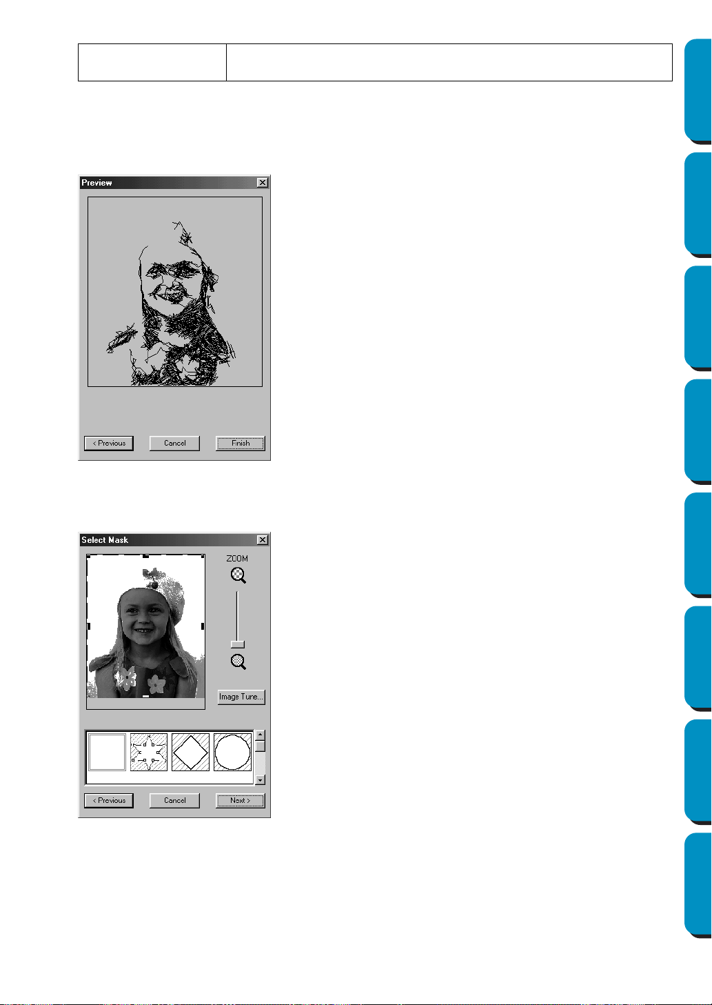
190
Contents Before Using Getting Started Design Center Layout & Editing
Programmable
Stitch Creator
Quick Reference Alphabetic Index
4 Click Next in the Photo Stitch Parameters dialog to display a Preview dialog similar to the one
shown below.
The created embroidery data can be previewed in this dialog.
In addition, you can return to previous dialogs in order to change the settings.
If Photo Stitch 2 (Color) is selected:
1
A Select Mask dialog similar to the one shown below appears.
For details on the settings, refer to 1 of “If Photo Stitch 1 (Color) is selected:” on page 183.
In this dialog, set the boundaries of the Photo Stitch and make adjustments to the image data.
Change Color
Click this button to open the Thread Color dialog, which lets you change
the thread color used in the embroidery data.
◆ Click Previous to return to the previous dia-
log.
◆ Click Finish to paste the created embroidery
data into the Design Page.
◆ Click Cancel to close this dialog.

191
Contents Before Using Getting Started Design Center Layout & Editing
Programmable
Stitch Creator
Quick Reference Alphabetic Index
2 In the Select Mask dialog, click Next to display the Photo Stitch Parameters dialog similar to the
one shown below.
Sewing Option:
Auto Select Setting:
Auto Select:
Click this button to select from the selected thread chart the thread colors closest to the four colors
in the selected color set. The selected thread colors appear in the Use Color List mentioned below.
This button can be clicked if the settings for Auto Select Setting have been changed.
Use Color List:
Allows the selected thread colors to be checked and edited.
◆ Specify the settings for creating Photo Stitch
data.
◆ Click Previous to return to the previous dia-
log.
◆ Click Next to apply the settings to the Photo
Stitch data, and display the next dialog.
◆ Click Cancel to close this dialog.
Line Interval
Specifies the interval of parallel lines used to create embroidery data.
Range: 1.2 - 5 mm (0.05 - 0.2 inch)
Default: 2 mm (0.08 inch)
Max. Density
Specifies the maximum density for areas of the created embroidery data
sewn with the zigzag stitch. The embroidery data will be created with a
density smaller than that set here.
Range: 2.5 - 5 lines per mm (64 - 127 lines per inch)
Default: 3 lines per mm (76 lines per inch)
Thread Chart
Selects the thread chart for selecting the thread color with the Auto
Select function.
The most appropriate thread color from the selected thread chart is
selected.
A user thread chart can also be selected.
Color Set
Sets the combination of four colors used when creating embroidery
data.
The color choices are: cyan (C), magenta (M), yellow (Y), black (K), red
(R), green (G) and blue (B). Select one of the following combinations
that contains the colors most used in the image.
Color combinations: CMYK, RGBK, CRYK, BMYK
Line interval
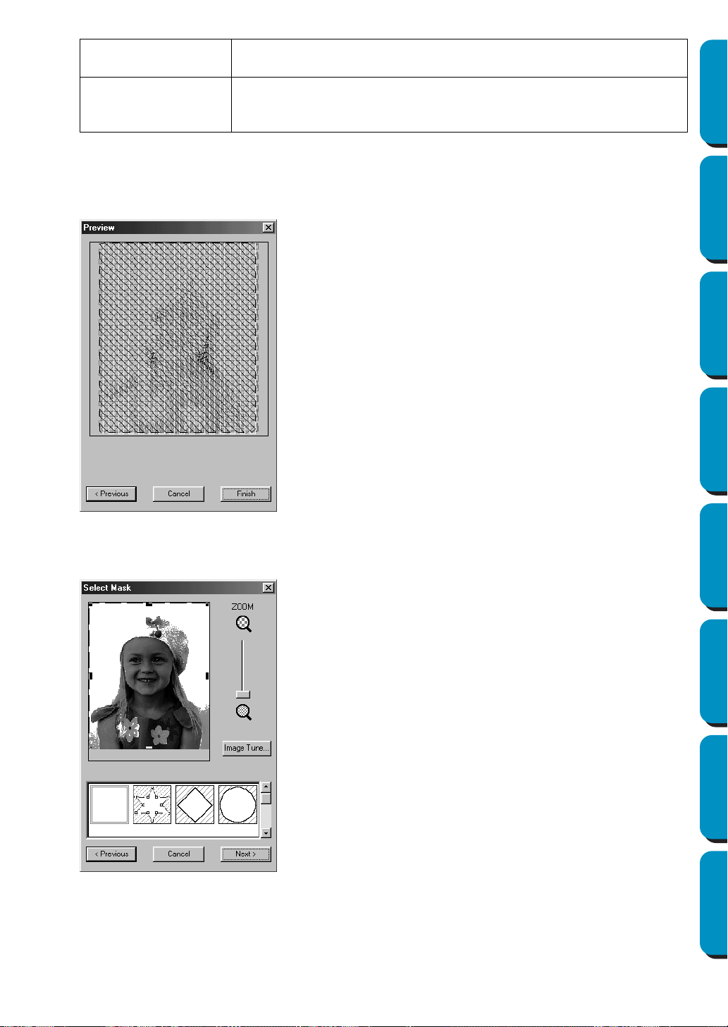
192
Contents Before Using Getting Started Design Center Layout & Editing
Programmable
Stitch Creator
Quick Reference Alphabetic Index
3 Click Next in the Photo Stitch Parameters dialog to display a Preview dialog similar to the one
shown below.
The created embroidery data can be previewed in this dialog.
In addition, you can return to previous dialogs in order to change the settings.
If Photo Stitch 2 (Mono) is selected:
1
A Select Mask dialog similar to the one shown below appears.
For details on the settings, refer to 1 of “If Photo Stitch 1 (Color) is selected:” on page 183.
In this dialog, set the boundaries of the Photo Stitch and make adjustments to the image data.
Use Color List
Summary
Displays the four selected thread colors.
Change Color
Select the color that you want to edit from the list, and then click this but-
ton to open the Thread Color dialog, which lets you edit the thread color
used in the embroidery data.
◆ Click Previous to return to the previous dia-
log.
◆ Click Finish to paste the created embroidery
data into the Design Page.
◆ Click Cancel to close this dialog.
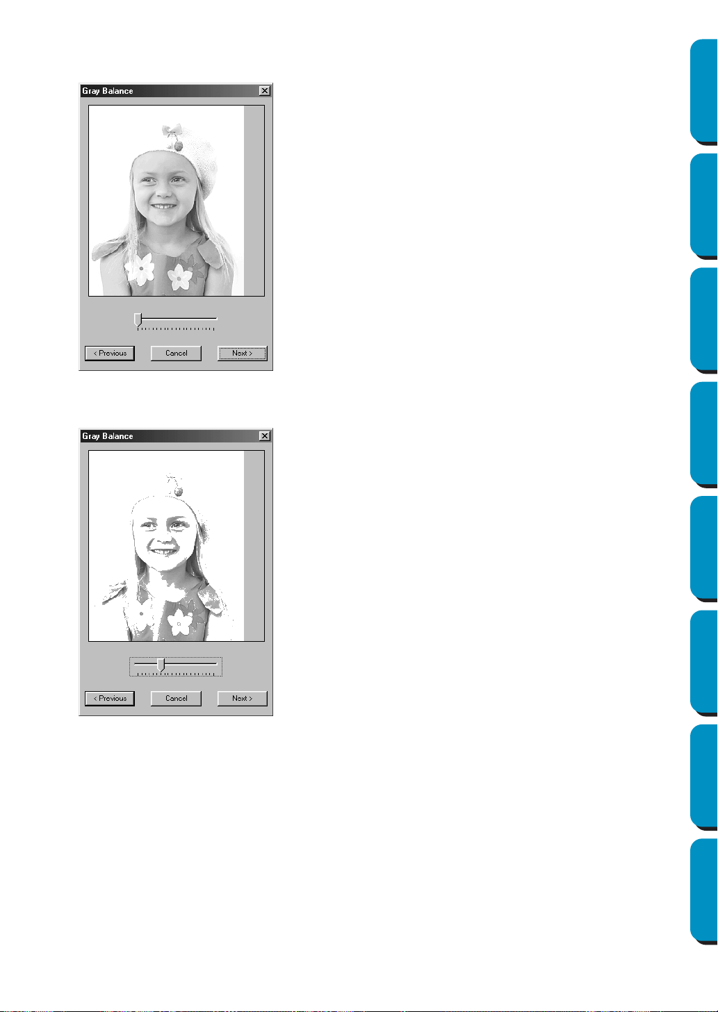
193
Contents Before Using Getting Started Design Center Layout & Editing
Programmable
Stitch Creator
Quick Reference Alphabetic Index
2 In the Select Mask dialog, click Next to display the Gray Balance dialog similar to the one shown
below.
Drag the slider to specify which parts of the image embroidery data will be created.
Data will be created for any areas remaining in black.
◆ Click Previous to return to the previous dia-
log.
◆ Click Next to display the next dialog.
◆ Click Cancel to close this dialog.

194
Contents Before Using Getting Started Design Center Layout & Editing
Programmable
Stitch Creator
Quick Reference Alphabetic Index
3 In the Gray Balance dialog, click Next to display the Photo Stitch Parameters dialog similar to the
one shown below.
Sewing Option:
Use Color:
Specifies the color of thread used to create the embroidery data.
The default setting is the darkest color in the current thread chart.
4 Click Next in the Photo Stitch Parameters dialog to display a Preview dialog similar to the one
shown on page 195.
◆ Specify the settings for creating Photo Stitch
data.
◆ Click Previous to return to the previous dia-
log.
◆ Click Next to apply the settings to the Photo
Stitch data, and display the next dialog.
◆ Click Cancel to close this dialog.
Line Interval
Specifies the interval of parallel lines used to create embroidery data.
Range: 1.2 - 5 mm (0.05 - 0.2 inch)
Default: 2 mm (0.08 inch)
Max. Density
Specifies the maximum density for areas of the created embroidery data
sewn with the zigzag stitch. The embroidery data will be created with a
density smaller than that set here.
Range: 2.5 - 5 lines per mm (64 - 127 lines per inch)
Default: 3 lines per mm (76 lines per inch)
Change Color
Click this button to open the Thread Color dialog, which lets you change
the thread color used in the embroidery data.
Line interval
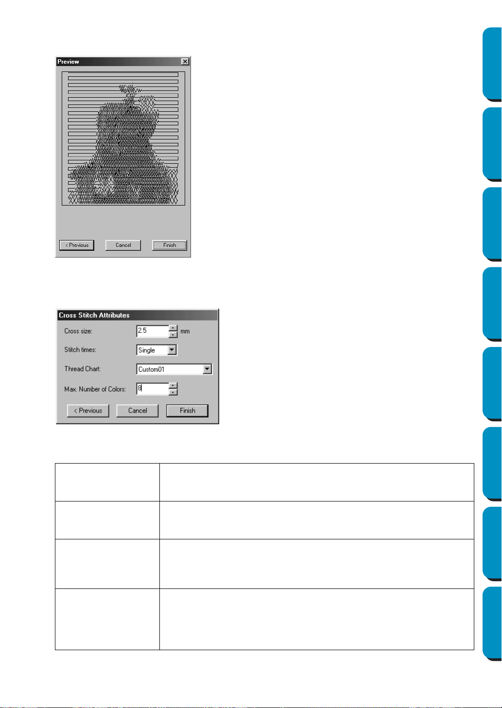
195
Contents Before Using Getting Started Design Center Layout & Editing
Programmable
Stitch Creator
Quick Reference Alphabetic Index
The created embroidery data can be previewed in this dialog.
In addition, you can return to previous dialogs in order to change the settings.
If Cross Stitch is selected:
1
The following Cross Stitch Attributes dialog appears.
◆ Click
Previous to return to the previous dia-
log.
◆ Click Finish to paste the created embroidery
data into the Design Page.
◆ Click
Cancel to close this dialog.
◆ Specify the settings for cross stitches.
◆ Click Previous to return to the previous
dialog.
◆ Click Finish to paste the created
embroidery data into the Design Page.
◆ Click Cancel to close this dialog.
Cross size
Sets the horizontal and vertical size of the pattern.
Range: 1.5 - 5 mm (0.04 - 0.39 inch)
Default: 2.5 mm (0.08 inch)
Stitch times
Sets the number of times that the pattern will be sewn. Sews twice per time.
Range: Single, Double, Triple
Default: Single
Thread Chart
Selects the thread chart for selecting the thread color.
The most appropriate thread color from the selected thread chart is
selected.
A user thread chart can also be selected.
Max. Number of
Colors
Sets the number of colors used in the created data.
Embroidery data is created using no more than the number of colors
specified.
Range: 2 - 15
Default: 8
196
Contents Before Using Getting Started Design Center Layout & Editing
Programmable
Stitch Creator
Quick Reference Alphabetic Index
■ Display Image – On/Faded/Off
Purpose: Turns on or off the template image or displays it faded.
Shortcut key:
Toolbar: No button for this function
Operation:
1 Click Display, then Template, then select the desired setting.
◆ Click
On to display the original image.
◆ Click Faded to fade the image before displaying it.
◆ Click Off to hide the image.
This function is not available if a image is not open.
Press the shortcut key to switch between displaying the template image to displaying it faded to
hiding the image.
F6

197
Contents Before Using Getting Started Design Center Layout & Editing
Programmable
Stitch Creator
Quick Reference Alphabetic Index
Text Menu
The functions of the Tex t menu performs actions on text patterns, such as fitting text to a curved path.
■ Edit Text Letters
Purpose: Allows you to edit an entered text.
Shortcut key: +
Toolbar: No button for this function
Operation:
1 Select the text you want to edit. You cannot edit more than one text pattern at a time. If you select
more than one text pattern, this function is not available.
2 Click Text, then Edit Text Letters.
The Edit Text dialog displays.
NOTE:
If text converted from a TrueType font is selected, the list of characters displayed is for the font of
the first letter of the text.
Edit Text Letters Allows you to edit an entered text. page 197
Text Attribute Setting
Allows for precise control of character
attributes.
page 198
Fit Text to Path Setting Fits a line of text along a path. page 199
Release Text from Path Release the text from the path. page 201
Transform Text Applies a preset transformation to text. page 201
Clear Transformation Restores the original shape of the text. page 202
True Type Font Attribute Setting
Sets the attributes, such as the style,
for TrueType fonts that are converted to
embroidery data.
page 202
Convert to Outline Object
Creates outline data from text data con-
verted from a TrueType font
page 203
◆ The selected text is highlighted in the text
field.
◆ Edit your text as needed by deleting
unwanted characters and typing or enter-
ing other characters by clicking them one
at the time on the character table, then
clicking
Insert or simply by double-clicking
them. Press the key to enter new
lines of text.
◆ Click OK to confirm.
◆ Click Cancel to exit.
• If a character that you entered is not avail-
able for the selected font, a warning mes-
sage displays. Click
OK in that dialog to
close it and to return to the Edit Text dialog
where you can correct your text.
Ctrl L
Enter
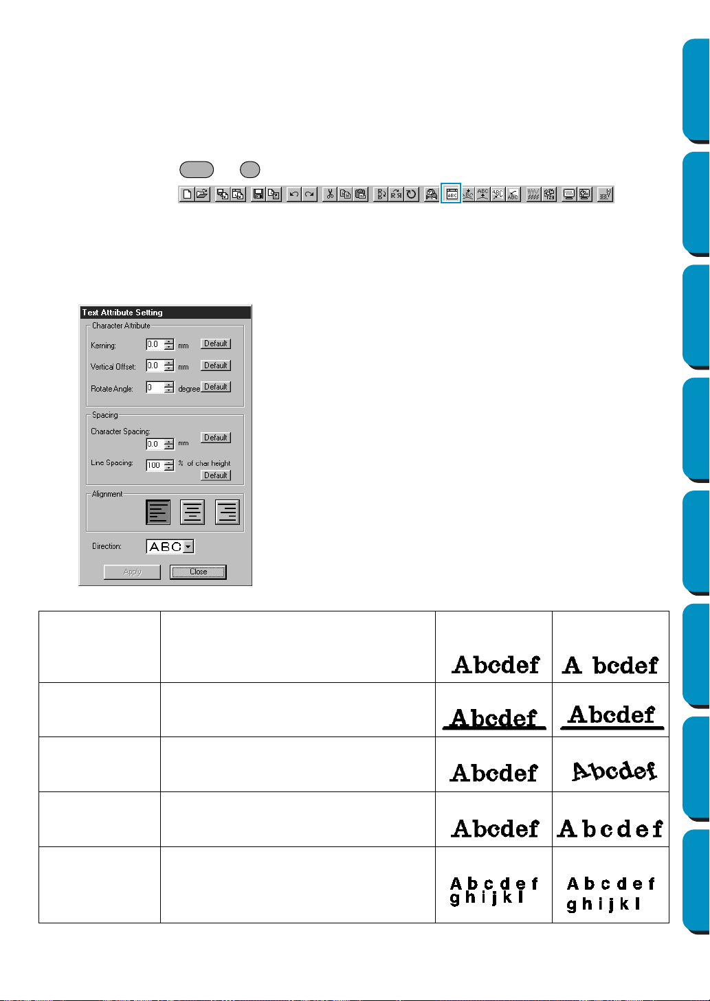
198
Contents Before Using Getting Started Design Center Layout & Editing
Programmable
Stitch Creator
Quick Reference Alphabetic Index
If text made from multiple TrueType fonts is selected, the list of characters displayed is for the font
of the first letter of the text.
See also: “Entering text” on page 127
■ Text Attribute Setting
Purpose: Allows for precise control of character attributes.
Shortcut key: +
Toolbar:
Operation:
1 Select one or more text patterns.
2 Click Text, then Text Attribute Setting.
The
Text Attribute Setting dialog displays.
◆ Enter the desired values for each set-
ting.
◆ To restore the default value of an indi-
vidual setting, click its Default button.
◆ Click Apply to confirm the effect of the
setting.
◆ Click Close to remove the dialog.
Kerning
Sets the spacing between individual char-
acters.
Range: -100 - 100 mm (-3.94 - 3.94 inches)
Default: 0
0.0 mm 5.0 mm (between
“A” and “b”)
Vertical Offset
Moves the text vertically.
Range: -100 - 100 mm (-3.94 - 3.94 inches)
Default: 0
0.0 mm 2.0 mm
Rotate angle
Rotates the characters.
Range: 0 - 359 degrees
Default: 0
0 degree 20 degree
Character
Spacing
Sets the spacing between all characters.
Range: -100 - 100 mm (-3.94 - 3.94 inches)
Default: 0
0.0 mm 2.0 mm
Line Spacing
Sets the spacing between lines in percents
of the character height.
Range: 0 – 1000%
Default: 0
100% 150%
Ctrl K
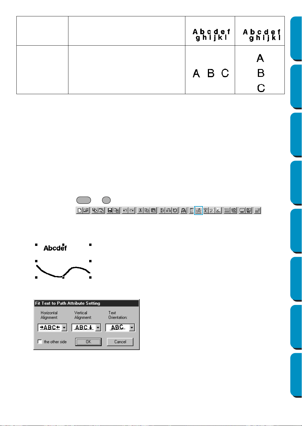
199
Contents Before Using Getting Started Design Center Layout & Editing
Programmable
Stitch Creator
Quick Reference Alphabetic Index
NOTE:
The vertical letters will be displayed in a vertical manner on design page.
NOTE:
Both Kerning and Character Spacing set the spacing between characters. The difference is that Char-
acter Spacing
is always applied to the entire text pattern, while Kerning can be applied to individual
characters. If you apply Kerning to the entire text pattern, it works exactly like Character Spacing. See
“Selecting characters on a text pattern” on page 123 for more details about selecting individual char-
acters in a text pattern.
See also: “Fit Text to Path Setting” below and “Transform Text” on page 201
■ Fit Text to Path Setting
Purpose: Fits a line of text along a path.
Shortcut key: +
Toolbar:
Operation:
1 Select a line of text and a path.
2 Click Text, then Fit Text to Path Setting.
Alignment
Aligns several lines of text to the left, cen-
ter or right.
Center Right
Direction
Specifies whether characters will be posi-
tioned horizontally or vertically.
Horizontal Vertical
◆ Select
Horizontal and Vertical Alignment and
Text Orientation.
◆ Check the other side if you want the characters
to be reversed.
◆ Click
OK to confirm the setting.
◆ Click
Cancel to exit.
Ctrl T
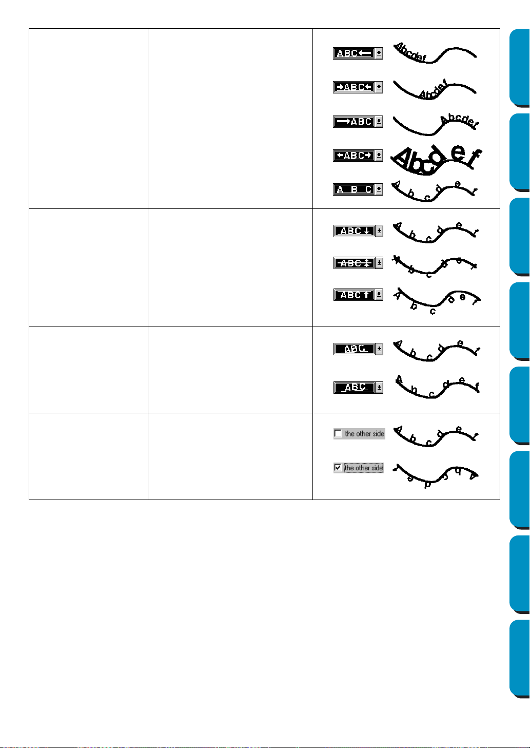
200
Contents Before Using Getting Started Design Center Layout & Editing
Programmable
Stitch Creator
Quick Reference Alphabetic Index
See also: “Release Text from Path” on page 201
Horizontal Alignment
Sets the distribution of characters
along the path.
Vertical Alignment
Sets the distance between the
text and the path.
Text Orientation
Sets the orientation of the char-
acters relative to the path.
The other side Reverses the characters.
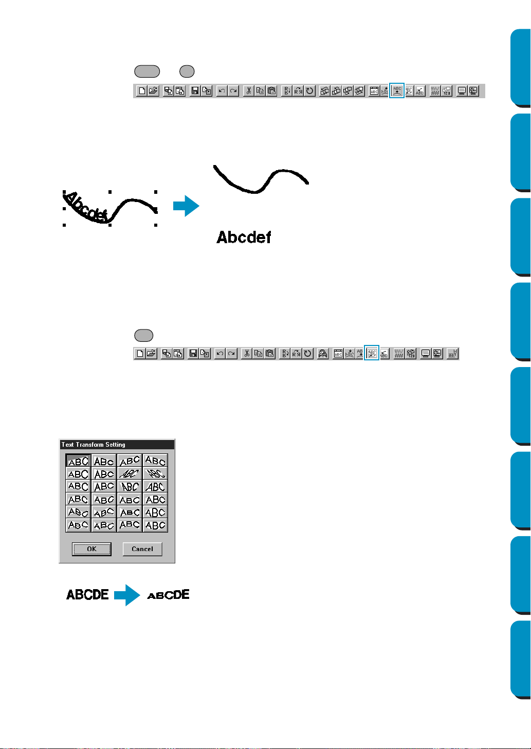
201
Contents Before Using Getting Started Design Center Layout & Editing
Programmable
Stitch Creator
Quick Reference Alphabetic Index
■ Release Text from Path
Purpose: Release the text from the path.
Shortcut key: +
Toolbar:
Operation:
1 Select a text fitted to a path.
2 Click Text, then Release Text from Path.
See also: “Fit Text to Path Setting” on page 199
■ Transform Text
Purpose: Applies a preset transformation to text.
Shortcut key:
Toolbar:
Operation:
1 Select a line of text.
2 Click Text, then Transform Text.
The Text Transform Setting dialog displays.
3 If necessary, set the level of transformation. See “Transform level” on page 141.
NOTE:
Take note that text data that has been changed from True Type font has data for both line and
region sewing, so if you use this function, depending on the form of the True Type font, there may
be a gap between the line and the region of the text.
See also: “Clear Transformation” on page 202
◆ Click on the desired transformation.
◆ Click OK or double-click to apply the transfor-
mation.
◆ Click Cancel to exit.
Ctrl Q
F2
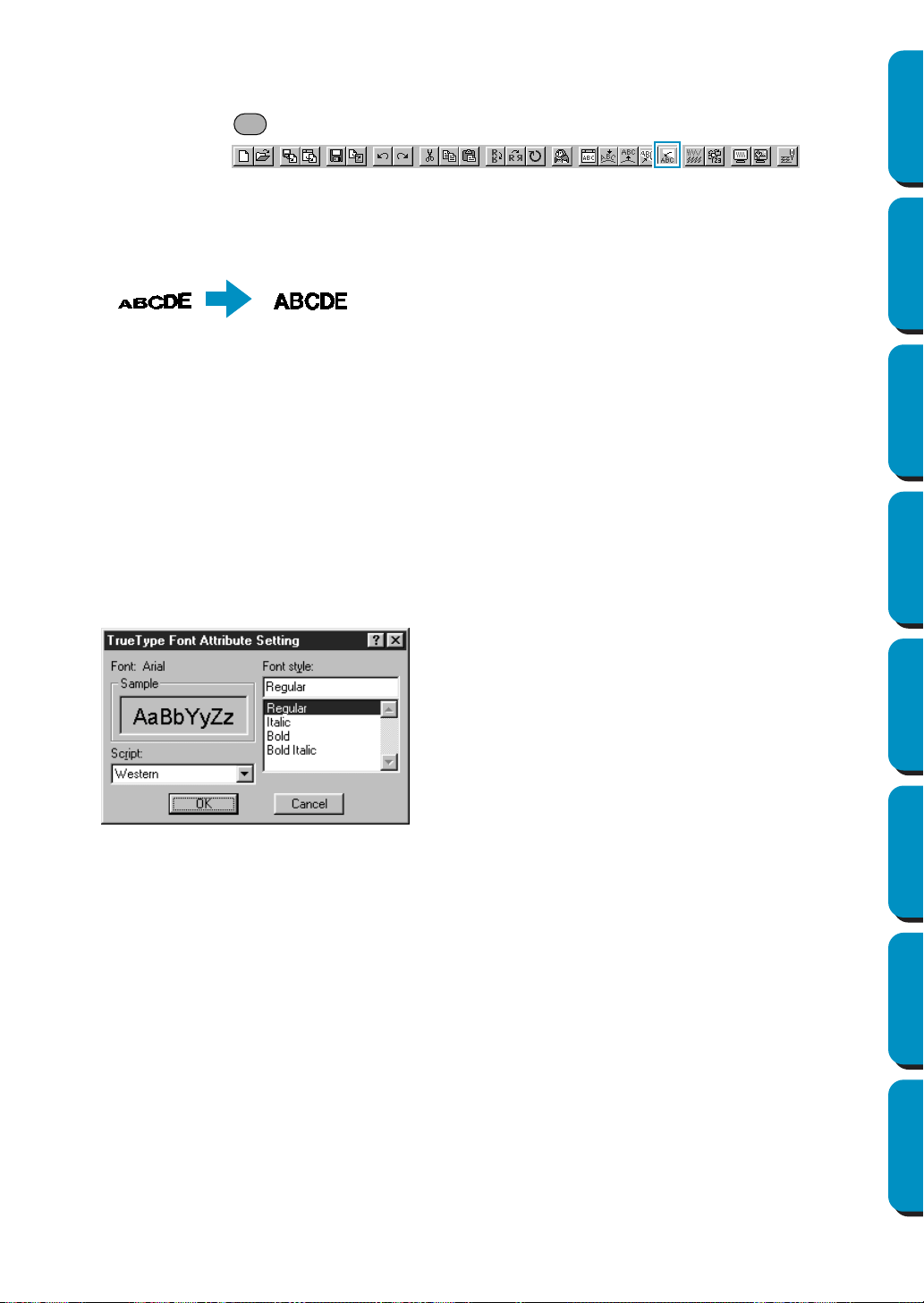
202
Contents Before Using Getting Started Design Center Layout & Editing
Programmable
Stitch Creator
Quick Reference Alphabetic Index
■ Clear Transformation
Purpose: Restores the original shape of the text.
Shortcut key:
Toolbar:
Operation:
1 Select transformed text.
2 Click Text, then Clear Transformation.
See also: “Transform Text” on page 201
■ TrueType Font Attribute Setting
Purpose: Sets the attributes, such as the style, for TrueType fonts that are converted to
embroidery data.
Shortcut key: No shortcut key for this function
Toolbar: No button for this function
Operation:
1 Click Text, then TrueType Font Attribute Setting
A dialog similar to the one shown below appears.
If any characters converted from a True-
Type font is selected, the attributes for the
selected characters are displayed.
◆ The Font attribute indicates the name
of the selected font.
◆ The
Sample box shows a sample of
the font with the selected attributes.
◆ Use
Font Style to select the desired
font style.
◆ Use
Script to select the desired char-
acter set for the font.
◆ Click
OK to set the attributes and close
the dialog.
Any entered TrueType font text will be
converted to embroidery data with the
font’s new attribute settings.
In addition, selecting text data con-
verted from a TrueType font creates
embroidery data based on the new
attribute settings.
◆ Click Cancel to close the dialog without
changing any settings.
F3
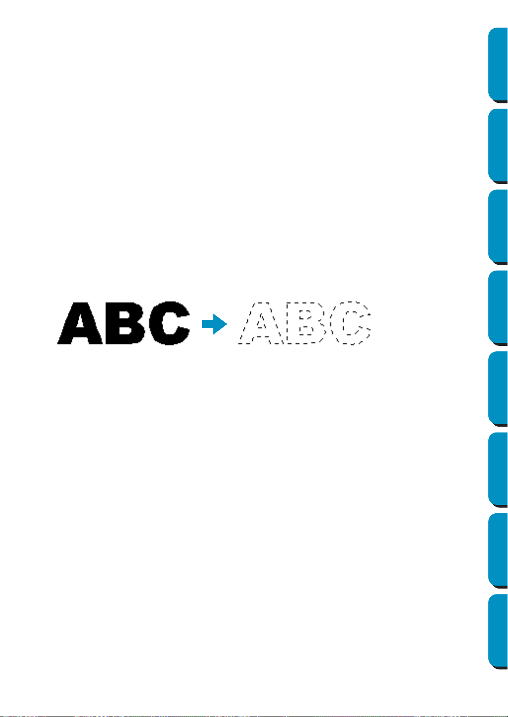
203
Contents Before Using Getting Started Design Center Layout & Editing
Programmable
Stitch Creator
Quick Reference Alphabetic Index
For details on entering text, refer to “Text Input Mode” (page 127).
NOTE:
The settings for Font Style and Script may differ depending on the TrueType font that is selected.
NOTE:
If text created from multiple TrueType fonts is selected, this dialog cannot be displayed.
In addition, if text of the same font but different font styles or scripts is selected, this dialog appears
with the attribute settings for the first letter in the text.
In either case mentioned above, selecting only one character from within text displays a dialog
containing only that character’s attributes.
See also: “Text Input Mode” on page 127, “Setting Text Attributes” on page 138
■ Convert to Outline Object
Purpose: Creates outline data from text data converted from a TrueType font
Shortcut key: No shortcut key for this function
Toolbar: No button for this function
Operation:
1 Select one or more text data converted from a TrueType font.
2 Click Text, then Convert to Outline Object.
The selected text data is converted to outline data.
None of the stitching settings are specified for the converted outline data; therefore, it appears as
dotted lines. Specify the stitching settings as necessary.
In order to prevent the pattern from losing its shape, group the objects or set them for hole sewing.
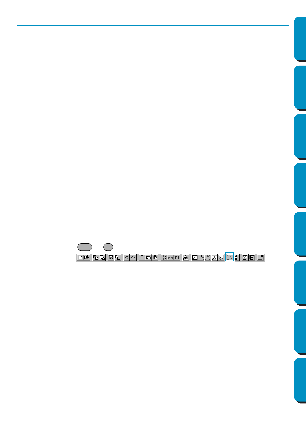
204
Contents Before Using Getting Started Design Center Layout & Editing
Programmable
Stitch Creator
Quick Reference Alphabetic Index
Sew Menu
The Sew menu allows you to control the way each pattern will be sewn.
■ Sewing Attribute Setting
Purpose: Sets the sewing attributes of the regions and the outlines of a pattern.
Shortcut key: +
Toolbar:
Operation:
1 Select one of the buttons of the Tool Box used to draw or select an existing pattern.
Sewing Attribute Setting
Sets the sewing attributes of the regions and
the outlines of a pattern.
page 204
Sewing Order
Allows you to check and change the sewing
order of patterns
page 210
Set hole sewing
Sets a pair of patterns for hole sewing (to
avoid sewing twice at the same place when a
pattern covers another one).
page 212
Cancel hole sewing Cancels hole sewing setting. page 213
Stitch to Block
Converts imported stitch patterns into blocks
(manual punching data), allowing you to set
sewing attributes and to keep the stitching
quality when scaling.
page 213
Convert to Stitch Converts a shape object to a stitch object. page 214
Change colors of a stitch object Changes the color of imported stitch data. page 215
Select Sewing Area Sets the sewing area page 216
Optimize hoop change
Optimizes the sewing order of patterns in a
Design Page for multi-position embroidery
frames (100 × 172 mm, 172 × 100 mm, 130 ×
300 mm, or 300 × 130 mm)
page 217
Optimize Entry/Exit points
Optimizes the positions of the entry points
and the exit points for the sewing data
page 218
Ctrl W
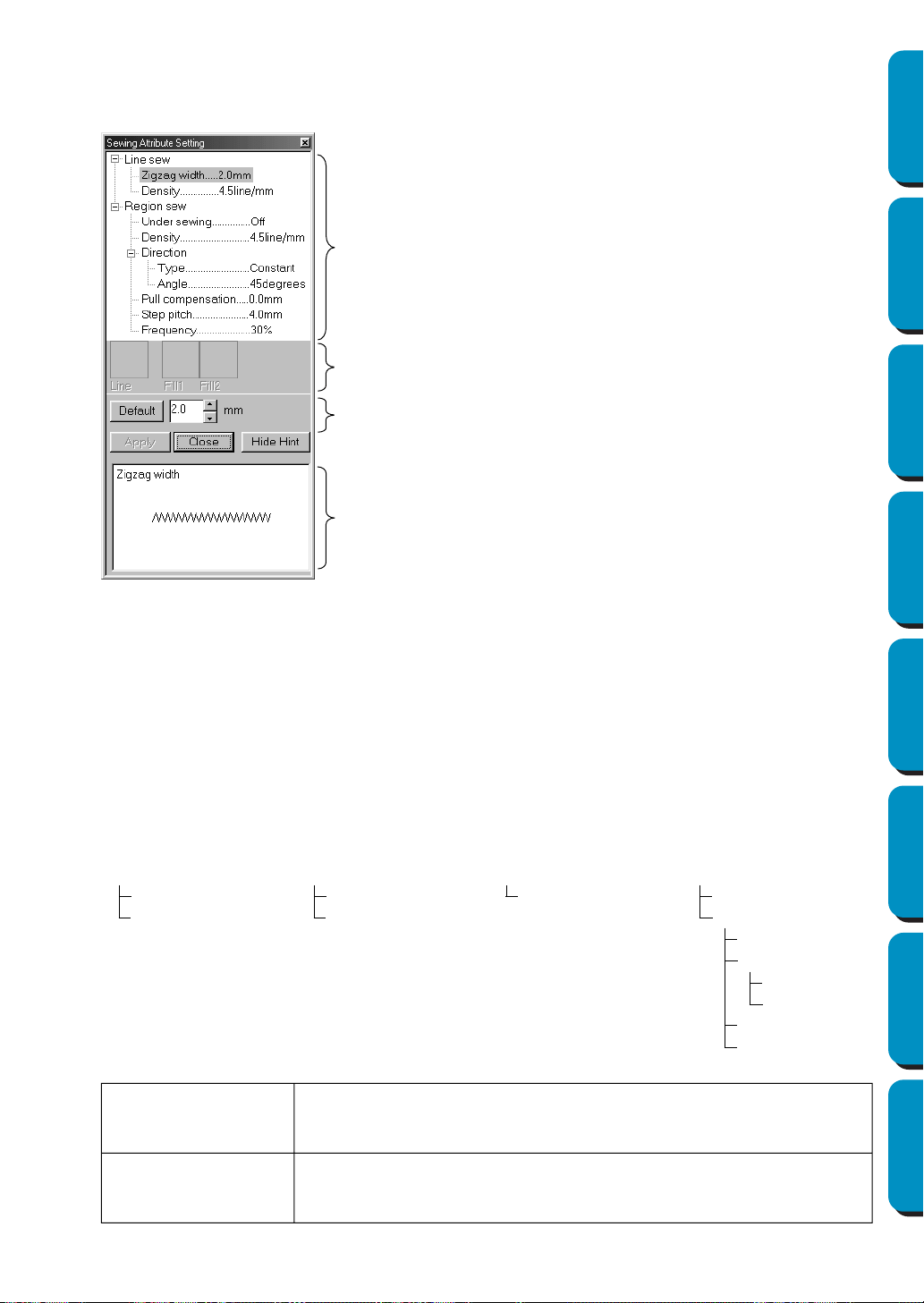
205
Contents Before Using Getting Started Design Center Layout & Editing
Programmable
Stitch Creator
Quick Reference Alphabetic Index
2 Click Sew, then Sewing Attribute Setting.
A Sewing Attribute Setting dialog similar to this will display.
You can change the size of this dialog as you like.
Sewing attribute display area: Displays the present settings for each of the sewing attributes.
Selected pattern display area:When a pattern for Programmable Fill or Motif sewing is selected,
that pattern is displayed.
Edit box: Displays the setting values to be changed for the item selected in
the Sewing attribute display area.
Hint image display area: When set to display a hint, a hint image showing the settings in the
edit box is displayed.
◆ Select the item you want to change or
set in the Sewing attribute display
area, then enter the change or setting
in the edit box.
◆ The method for entering the setting
varies according to the item. If enter-
ing numerical values, you can click on
the arrow buttons to select values or
enter the values directly. If the Default
button is displayed in the Edit box,
click the button to apply the Default
setting to the selected item.
◆ Click
Apply to confirm the setting.
◆ Click
Close to exit.
◆ Click Show Hint/Hide Hint to turn the
hint image display on or off.
Line sewing attributes
Setting items according to the selected stitch
Zigzag stitch
Line sewing
Zigzag width
Density
Running stitch
Line sewing
Run pitch
Run times
Manual Punch
Line sewing
Run pitch
Motif stitch
Line sewing
Run pitch
Motif
Pattern
Pattern size
Width
Height
H-Arrange
V-Arrange
Zigzag width
Sets the width of the zigzag.
Range: 1 - 10 mm (0.04 - 0.39 inch)
Default: 2 mm (0.08 inch)
Density
Sets the number of lines per mm (inch).
Range: 1 - 7 lines per mm (25 - 178 lines per inch)
Default: 4.5 lines per mm (114 lines per inch)
Sewing attribute
Selected pattern
Edit box
Hint image display area
display area
display area
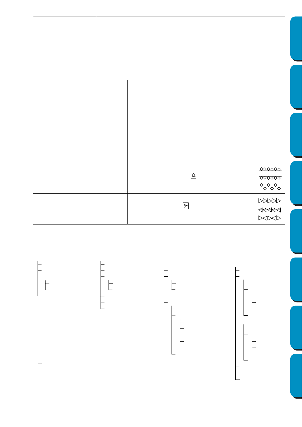
206
Contents Before Using Getting Started Design Center Layout & Editing
Programmable
Stitch Creator
Quick Reference Alphabetic Index
Run pitch
Sets the pitch of the line sewing.
Range: 1 - 10 mm (0.04 - 0.39 inch)
Default: 2 mm (0.08 inch)
Run times
Sets the number of times the border will be sewn.
Range: 1 - 5
Default: 1
Motif Stitch only:
Pattern
Select a pattern for Motif sewing.
Click Select Pattern, and the Browse dialog will display. Select
the folder containing the pmf file you want to open. Scroll
through the available stitch patterns and double-click the
desired pattern or click OK to select the pattern
Pattern Size
Width
Sets the pattern width (the direction along the line).
Range: 2 - 10 mm (0.08 - 0.39 inch)
Default: 5 mm (0.20 inch)
Height
Sets the pattern height (the direction perpendicular to the line).
Range: 2 - 10 mm (0.08 - 0.39 inch)
Default: 5 mm (0.20 inch)
H-Arrange
(Horizontal Arrange)
Sets the horizontal arrangement of the
pattern. For patterns like , patterns will
be arranged along the line as shown to the
right.
V-Arrange
(Vertical Arrange)
Sets the vertical arrangement of the pat-
tern. For patterns like , patterns will be
arranged along the line as shown to the
right.
Region sewing attribute
Setting items according to the selected stitch
Satin stitch
Region sewing
Under sewing
Density
Direction
Type
Angle
Pull compensation
Fill stitch
Region sewing
Under sewing
Density
Direction
Type
Angle
Pull compensation
Step pitch
Frequency
Programmable fill
Region sewing
Under sewing
Density
Direction
Type
Angle
Pull compensation
Programmable Fill
Pattern
Pattern size
Width
Height
Offset
Direction
Value
Direction
Motif stitch
Region sewing
Motif
Use pattern
Pattern1
Pattern
Pattern size
Width
Height
H-Arrange
V-Arrange
Pattern2
Pattern
Pattern size
Width
Height
H-Arrange
V-Arrange
Offset
Direction
Run pitch
Cross stitch
Size
Times
Normal:
Mirror:
Alternate:
Normal:
Mirror:
Alternate:
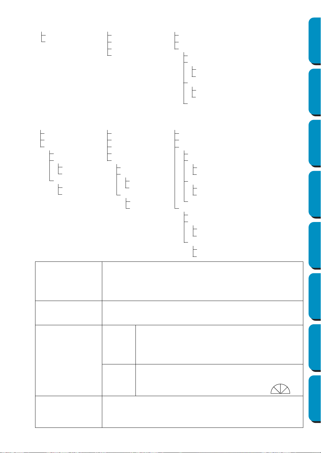
207
Contents Before Using Getting Started Design Center Layout & Editing
Programmable
Stitch Creator
Quick Reference Alphabetic Index
Text Satin stitch
Region sewing
Density
Pull compensation
Text Fill stitch
Region sewing
Density
Pull compensation
Step pitch
Frequency
Text Programmable Fill
Region sewing
Density
Pull compensation
Programmable Fill
Pattern
Pattern size
Width
Height
Offset
Direction
Value
Direction
Manual Punch Satin
stitch
Region sewing
Density
Pull compensation
Feathered edge
Feathered side
Top side
Pattern
Max length
Bottom side
Pattern
Max length
Manual Punch Fill
stitch
Region sewing
Density
Pull compensation
Step pitch
Frequency
Feathered edge
Feathered side
Top side
Pattern
Max length
Bottom side
Pattern
Max length
Manual Punch Pro-
grammable Fill
Region sewing
Density
Pull compensation
Programmable Fill
Pattern
Pattern size
Width
Height
Offset
Direction
Value
Direction
Feathered edge
Feathered side
Top side
Pattern
Max length
Bottom side
Pattern
Max length
Under Sewing
Sets under sewing on/off. Try to use Under sewing for wide areas, in order
to prevent shrinking during stitching. Depending on the shape of the region,
however, it may not be possible to make this setting.
On: Under sewing will be done
Off: Under sewing will not be done
Density
Sets the number of lines per mm.
Range: 1 - 7 lines per mm (25 - 178 lines per inch)
Default: 4.5 lines per mm (114 lines per inch)
Direction
Type
Specifies the type of sewing direction.
Constant: Sews at a fixed angle. The angle is specified by the
Angle setting.
Variable: Varies the sewing direction according to the object
being sewn.
Angle
Specifies the sewing angle.
(If
Variable
is selected as the
Type
setting, this setting is not available.)
Range: 0 - 179 degrees
Default: 45 degrees
Pull Compensation
Lengthens the sewing region in the stitch pattern’s sewing direction to pre-
vent pattern shrinkage during sewing.
Range:0 - 2 mm (0.00 - 0.08 inch)
Default:0 mm (0.00 inch)
0˚
45˚
90˚
135˚
179˚
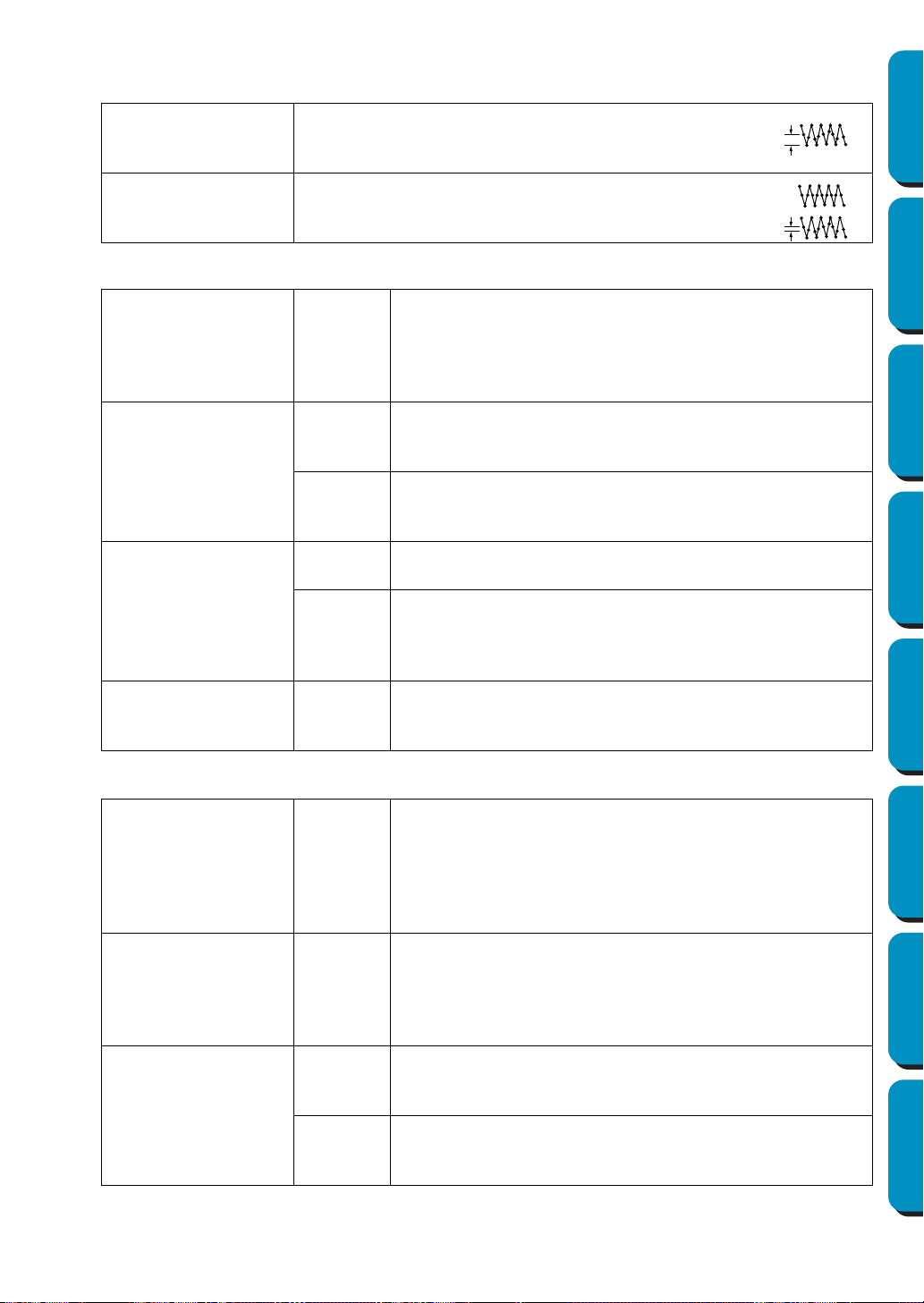
208
Contents Before Using Getting Started Design Center Layout & Editing
Programmable
Stitch Creator
Quick Reference Alphabetic Index
Fill stitch only:
Step Pitch
Sets the pitch of the steps.
Range: 1 - 10 mm (0.04 - 0.39 inch)
Default: 4 mm (0.16 inch)
Frequency
Sets the spacial frequency steps.
Range: 0 - 99%
Default: 30%
Programmable fill stitch only:
Pattern
Select a pattern for Programmable Fill Stitch.
Click Select Pattern, and the Browse dialog opens. Select the
folder containing the pas file you want to open. Scroll through
the available stitch patterns and double-click the desired pat-
tern or click OK to select the pattern
Pattern Size
Width
Sets the stitch pattern width.
Range: 5 - 10 mm (0.20 - 0.39 inch)
Default: 7.5 mm (0.30 inch)
Height
Sets the stitch pattern height.
Range: 5 - 10 mm (0.20 - 0.39 inch)
Default: 7.5 mm (0.30 inch)
Offset
Direction
Sets the offset arrangement of the pattern, and sets the direc-
tion of offset as Row/Column.
Value
When the pattern’s arrangement is offset, sets the amount of
offset.
Range: 0 - 99%
Default: 0%
Direction
Allows you to rotate the angle of the stitch patterns.
Range: 0 - 359 degrees
Default: 0 degrees
Motif Stitch only:
Use Pattern
Selects whether to use pattern 1 or pattern 2 for Motif. If you
choose to use both patterns, the data is created so that sewing
is alternated between them after each row.
Pattern1 only: Uses only pattern 1 (Default)
Pattern2 only: Uses only pattern 2
Pattern1 and 2: Uses pattern 1 and pattern 2
Pattern
Select a pattern for Motif sewing.
Click Select Pattern, and the Browse dialog will display. Select
the folder containing the pmf file you want to open. Scroll
through the available stitch patterns and double-click the
desired pattern or click OK to select the pattern.
Pattern Size
Width
Sets the pattern width (the direction along the line).
Range: 2 - 10 mm (0.08 - 0.39 inch)
Default: 5 mm (0.20 inch)
Height
Sets the pattern height (the direction perpendicular to the line).
Range: 2 - 10 mm (0.08 - 0.39 inch)
Default: 5 mm (0.20 inch)
Step pitch
0%
30%
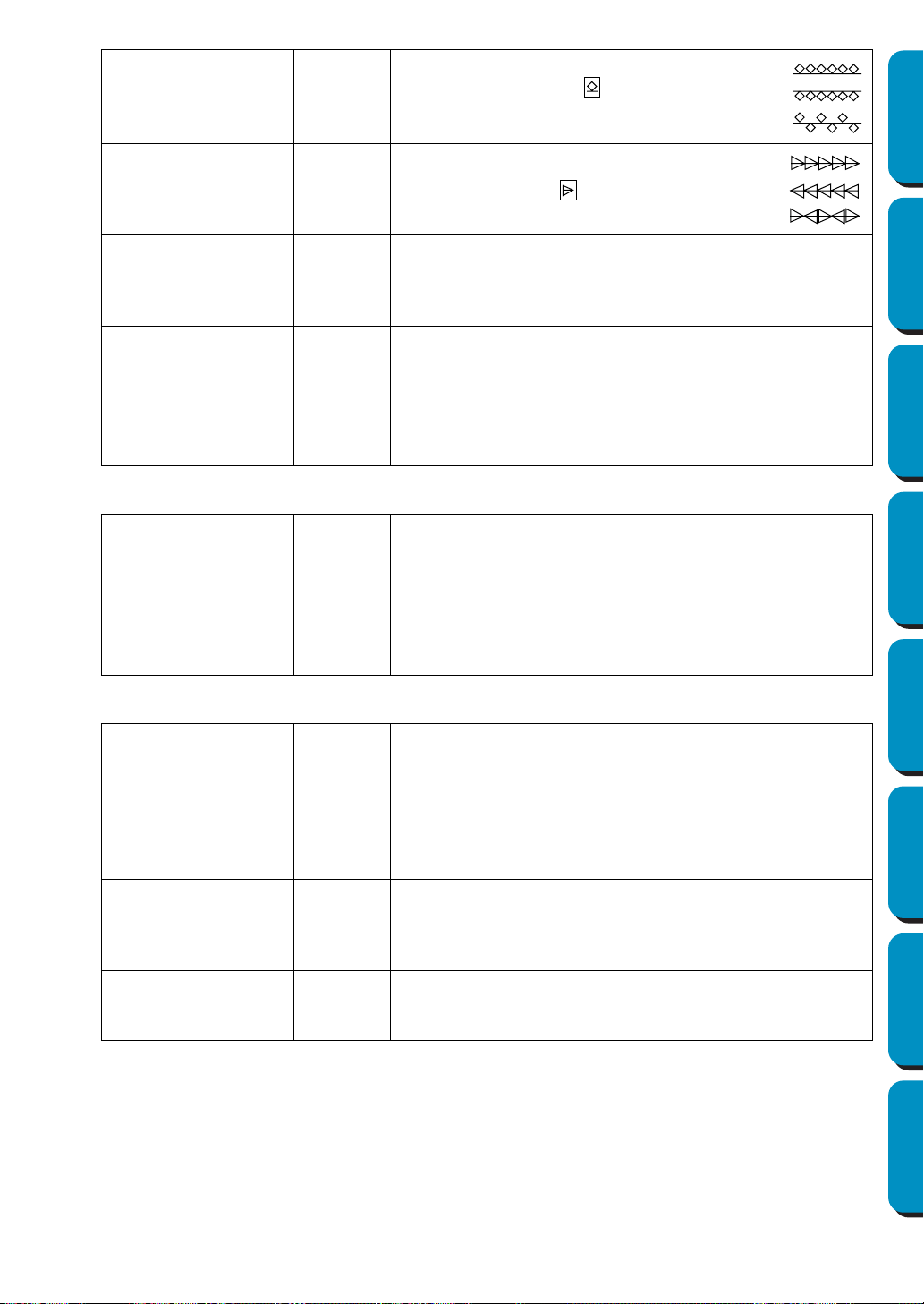
209
Contents Before Using Getting Started Design Center Layout & Editing
Programmable
Stitch Creator
Quick Reference Alphabetic Index
H-Arrange
(Horizontal Arrange)
Sets the horizontal arrangement of the
pattern. For patterns like , patterns will
be arranged along the line as shown
below.
V-Arrange
(Vertical Arrange)
Sets the vertical arrangement of the pat-
tern. For patterns like , patterns will be
arranged along the line as shown below.
Row Offset
When the pattern arrangement is offset, sets the amount of
offset for each row.
Range: 0 - 10 mm (0.06 - 0.20 inch)
Default: 0 mm (0.10 inch)
Direction
Allows you to rotate the angle of the Motif patterns.
Range: 0 - 359 degrees
Default: 0 degrees
Run Pitch
Sets the pitch of the sewing.
Range: 1 - 10 mm (0.04 - 0.39 inch)
Default: 2 mm (0.08 inch)
Cross stitch only:
Size
Sets the horizontal and vertical size of the pattern.
Range: 1.5 - 5 mm (0.06 - 0.20 inch)
Default: 2.5 mm (0.10 inch)
Times
Sets the number of times that the pattern will be sewn. Sews
twice per time.
Range: Single, Double, Triple
Default: Single
Feathered Edge only:
Feathered Side
Sets which side of the sewing direction to apply the Feathered
edge setting to.
When creating data in Manual Punch mode, the Topside has
organization points 1-3, and the Bottom side has organization
points 2-4.
Top: Feathered Edge is sewn on the Topside.
Bottom: Feathered Edge is sewn on the Bottomside.
Pattern
Selects a pattern to use with the Feathered Edge.
Click
Select Pattern, and the Browse dialog will open.
Scroll through the available Feathered Edge patterns and dou-
ble-click the desired pattern or click OK to select the pattern
Max length
Sets the length of feathered edge.
Range: 0.2 - 100 mm (0.01 - 3.94 inch)
Default: 3 mm (0.12 inch)
Normal:
Mirror:
Alternate:
Normal:
Mirror:
Alternate:

210
Contents Before Using Getting Started Design Center Layout & Editing
Programmable
Stitch Creator
Quick Reference Alphabetic Index
Note on the Programmable Fill Stitch:
When setting the stitch and pattern directions of a programmable stitch, take note that whenever
the stitch and pattern direction settings cause the stitch to be sewn in the same direction as a line
in a stitch pattern, that line will not be sewn.
Use the preview function of your application to view exactly how your stitch pattern will be sewn
and set the stitch direction and pattern direction according to the selected stitch or to the effect
that you want to produce. To get an even better view, make test samples of different settings.
Example of a programmable fill stitch
See also: “Preview” on page 220, “Programmable Stitch Creator” on page 233
■ Sewing Order
Purpose: Allows you to check and change the sewing order of patterns
Shortcut key:
Toolbar:
(Example of a feathered side pattern)
Example 2:
Stitch direction: 90˚
Example 1:
Stitch direction: Default: 45˚
Example 3:
Stitch direction: 0˚
F10
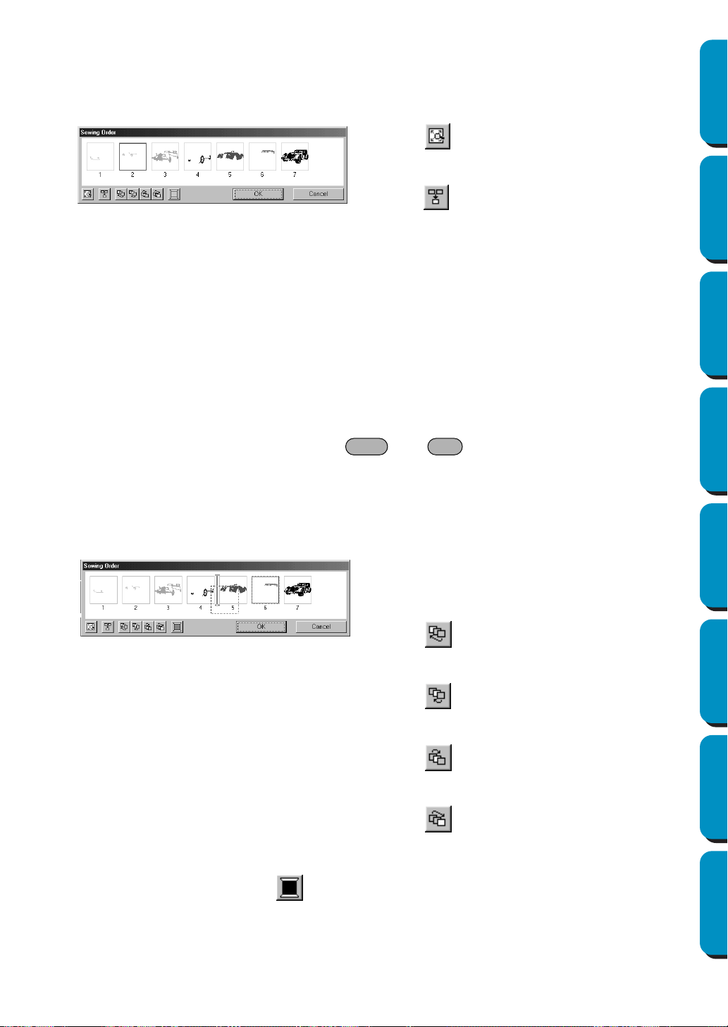
211
Contents Before Using Getting Started Design Center Layout & Editing
Programmable
Stitch Creator
Quick Reference Alphabetic Index
Operation:
1 Click Sew, then Sewing Order.
A dialog similar to the one shown below appears. The dialog can be made longer so that all parts
of the pattern can be viewed.
Selecting data:
Select a pattern by clicking it. The selected pattern is framed with a thick line and the correspond-
ing area in the Design Page is surrounded with a dotted line.
To select multiple patterns, hold down the and keys while clicking the patterns. In
addition, multiple patterns can be selected by dragging the pointer over them.
Changing the sewing order:
The sewing order can be changed by selecting a pattern and dragging it to the desired location.
The destination location is indicated by the red line while the pattern is being dragged, and the
selected data is moved to the indicated location once the pattern is released.
Changing the color:
Select a pattern, and then click to display the Thread Color dialog that allows the thread color
to be changed.
NOTE:
The frames around whole objects (with no hole settings applied) or objects with no sewing settings
applied will be a dotted line. In addition, there will be no number for the sewing order below the
frame.
◆ Click to enlarge each pattern to fill its
frame.
◆ Click to display in one frame all patterns
of the same color that will be sewn together. If
multiple patterns are displayed in a frame, a
plus sign (+) appears beside the number of
that frame.
◆ Click OK to apply the settings and close the
dialog.
◆ Click Cancel to close the dialog without chang-
ing the settings.
In addition, after a pattern is selected, its sewing
order can be changed by clicking the following but-
tons.
◆ Click to move the selected pattern to the
beginning of the sewing order.
◆ Click to move the selected pattern ahead
one position in the sewing order.
◆ Click to move the selected pattern back
one position in the sewing order.
◆ Click to move the selected pattern to the
end of the sewing order.
Shift Ctrl
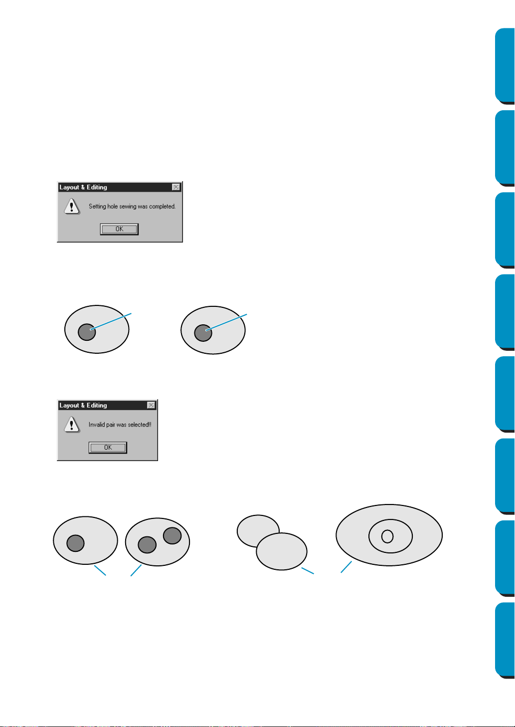
212
Contents Before Using Getting Started Design Center Layout & Editing
Programmable
Stitch Creator
Quick Reference Alphabetic Index
■ Set hole sewing
Purpose: Sets a pair of patterns for hole sewing (to avoid sewing twice at the same place
when a pattern covers another one).
Shortcut key: No shortcut key for this function
Toolbar: No button for this function
Operation:
1 Select a pair of patterns, for example, a rectangle included in another rectangle.
2 Click Sew, then Set Hole Sewing.
This message will display.
3 Once a pair of patterns has been set for hole sewing, they are grouped and will move together if
you try to move one of the patterns. To change their relative position, you will have to cancel hole
sewing first.
If the selected pair cannot be set for hole sewing, this message displays.
For a pair to be valid, one of the pattern must be completely enclosed within the other pattern of
the pair.
Note that you can see better what the hole sewing setting does by previewing the pair before and
after setting the pair for hole sewing (see “Preview” on page 220).
See also: “Cancel hole sewing” on page 213
◆ Click
OK to remove the message.
◆ Click OK to remove the message.
Hole sewing not set
Hole sewing set
Sewn twice
Sewn once
Valid
Invalid

213
Contents Before Using Getting Started Design Center Layout & Editing
Programmable
Stitch Creator
Quick Reference Alphabetic Index
■ Cancel hole sewing
Purpose: Cancels hole sewing setting.
Shortcut key: No shortcut key for this function
Toolbar: No button for this function
Operation:
1 Select a pattern that has been set for hole sewing.
2 Click Sew, then Cancel Hole Sewing.
The pair of patterns can now be moved independently.
See also: “Set hole sewing” on page 212
■ Stitch to Block
Purpose: Converts imported stitch patterns into blocks (manual punching data), allowing
you to set sewing attributes and to keep the stitching quality when scaling.
Shortcut key: No shortcut key for this function
Toolbar: No button for this function
Operation:
1 Select the imported stitch data opened in the Design Page to which you want to apply the setting to.
2 Click Sew, then Stitch to Block.
This dialog displays.
NOTE:
Applying this function may affect the content of some patterns.
You may further modify the pattern if needed with the help of the
Point Edit Mode.
3 After applying this function, the Sewing Attributes bar displays as follows:
You can select and modify the sewing settings of the blocks of the same color.
To do this, select a block whose color or sewing settings you want to change. All the blocks of that
color are selected and the block color and stitch type display in the Sewing Attributes bar.
NOTE:
The sewing setting changes apply globally to the blocks of the same color.
Immediately after the operation, the data of the blocks is grouped, so they become one object.
◆ Select the sensitivity by dragging the
slider.
• The normal setting should provide satis-
factory results in most cases, but depend-
ing on the complexity of a pattern, you
may need to select a coarser or a finer
stitch density.
◆ Click OK to confirm.
◆ Click
Cancel to exit.
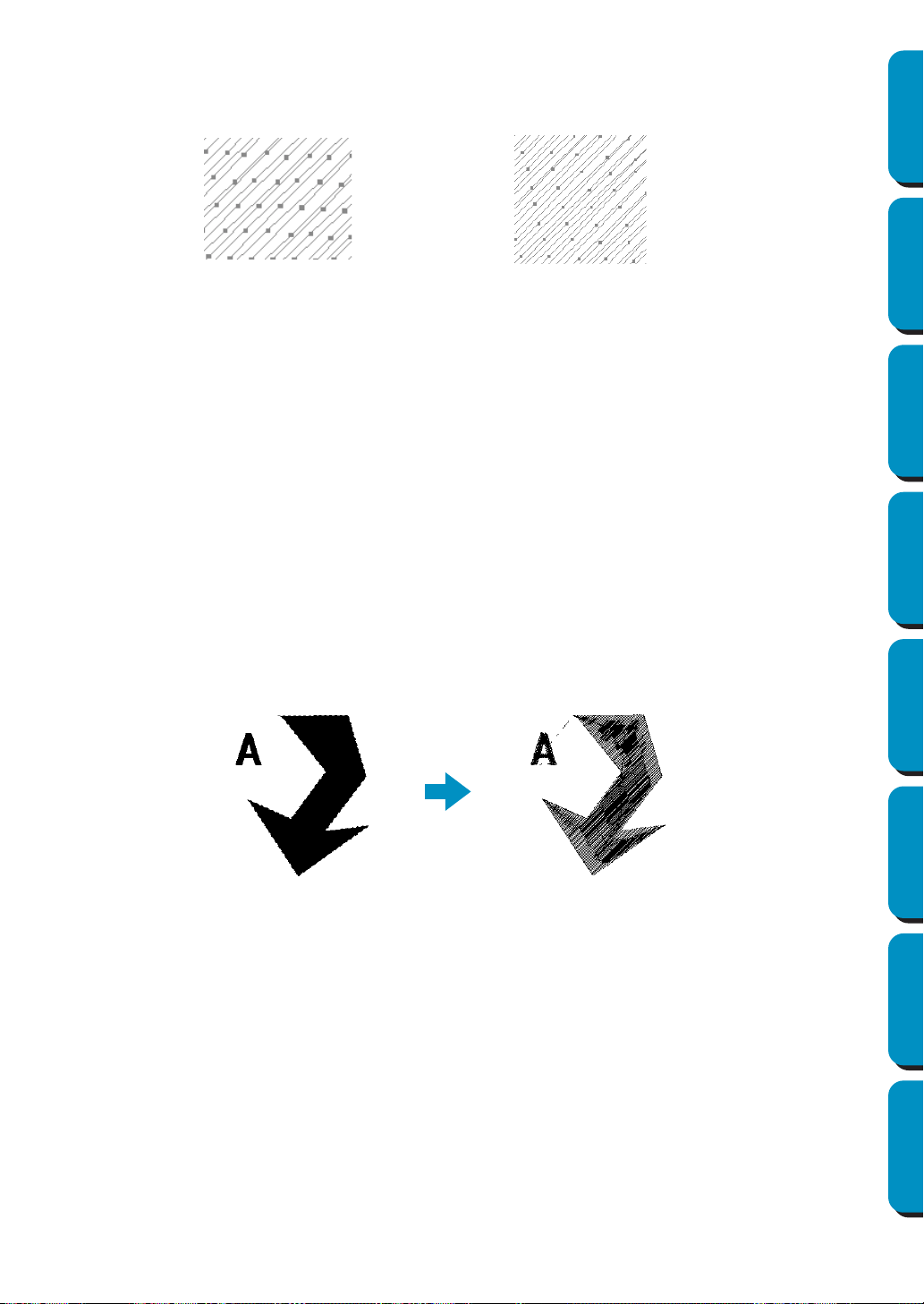
214
Contents Before Using Getting Started Design Center Layout & Editing
Programmable
Stitch Creator
Quick Reference Alphabetic Index
4 When you enlarge or reduce a converted pattern with the selection cursor, the number of stitches
sewn automatically adapt to the new size of the pattern, allowing you to keep the original embroi-
dery quality.
NOTE:
The selected color blocks can be moved or scaled individually, therefore, if you want to move the
whole pattern once it has been converted, be sure to select the whole pattern.
See also: “Sewing Attribute Setting” on page 204, “Scaling patterns” on page 118 and “Point
Edit Mode” on page 120
■ Convert to Stitch
Purpose: Converts a shape object to a stitch object.
Shortcut key: No shortcut key for this function
Toolbar: No button for this function
Operation:
1 Select one or more shape objects.
2 Click Sew, then Convert to Stitch.
The selected shape data is converted to stitch data.
The dotted line around the converted data indicates that it is stitch data.
Each stitch of the converted data can be edited with the point edit tool.
• Shape objects that can be converted are data created with the Circle, Rectangle, Outline, Manual
punch or Text tools.
• Related text, paths and objects set for hole sewing are all converted to stitch data, even if some
of the objects can be selected separately.
• If an object that does not have stitching settings applied is converted, that object is deleted.
Without Stitch to Block With Stitch to Block
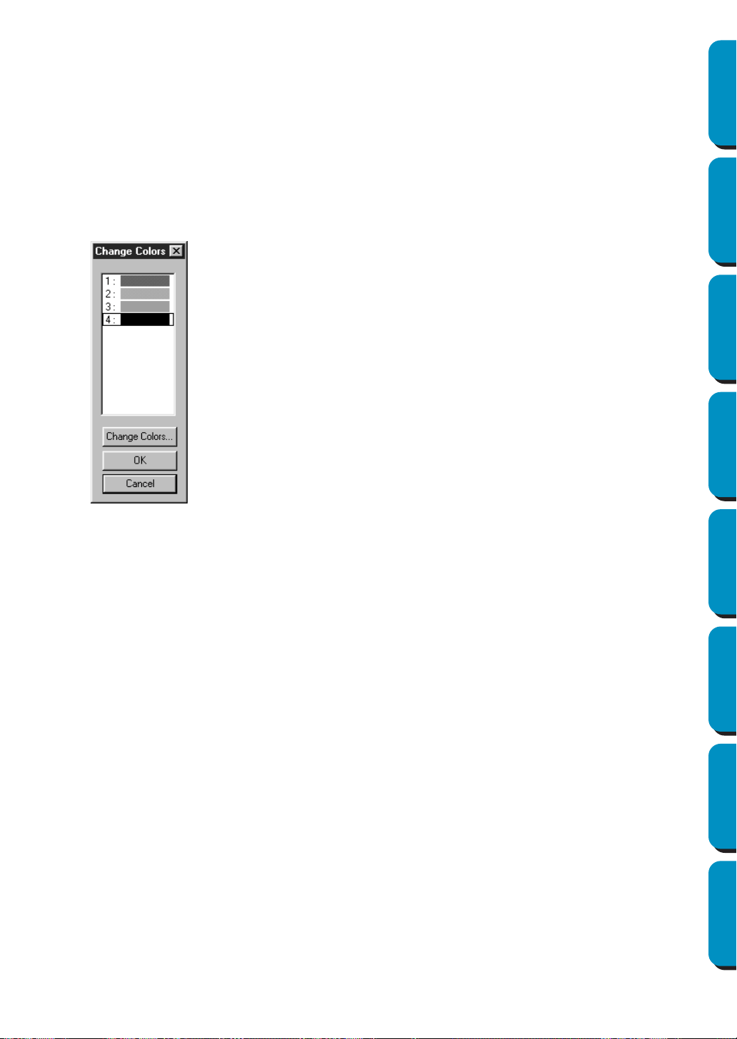
215
Contents Before Using Getting Started Design Center Layout & Editing
Programmable
Stitch Creator
Quick Reference Alphabetic Index
■ Change colors of a stitch object
Purpose: Changes the color of imported stitch data.
Shortcut key: No shortcut key for this function
Toolbar: No button for this function
Operation:
1 Select the pattern.
2 Click Sew, then Change colors of a stitch object.
The
Change colors dialog appears, listing and displaying the colors used for the selected pattern.
See also: “Color” on page 144
◆ Click the color you want to change.
◆ Click the Change Colors button.
◆ Select the desired color in the Region
Thread Color
dialog which displays.
The new color displays in the Change Col-
ors
dialog and the pattern displays the
new setting. Repeat this procedure for
each color you want to change.
◆ Click OK to confirm.
◆ Click Cancel to exit.
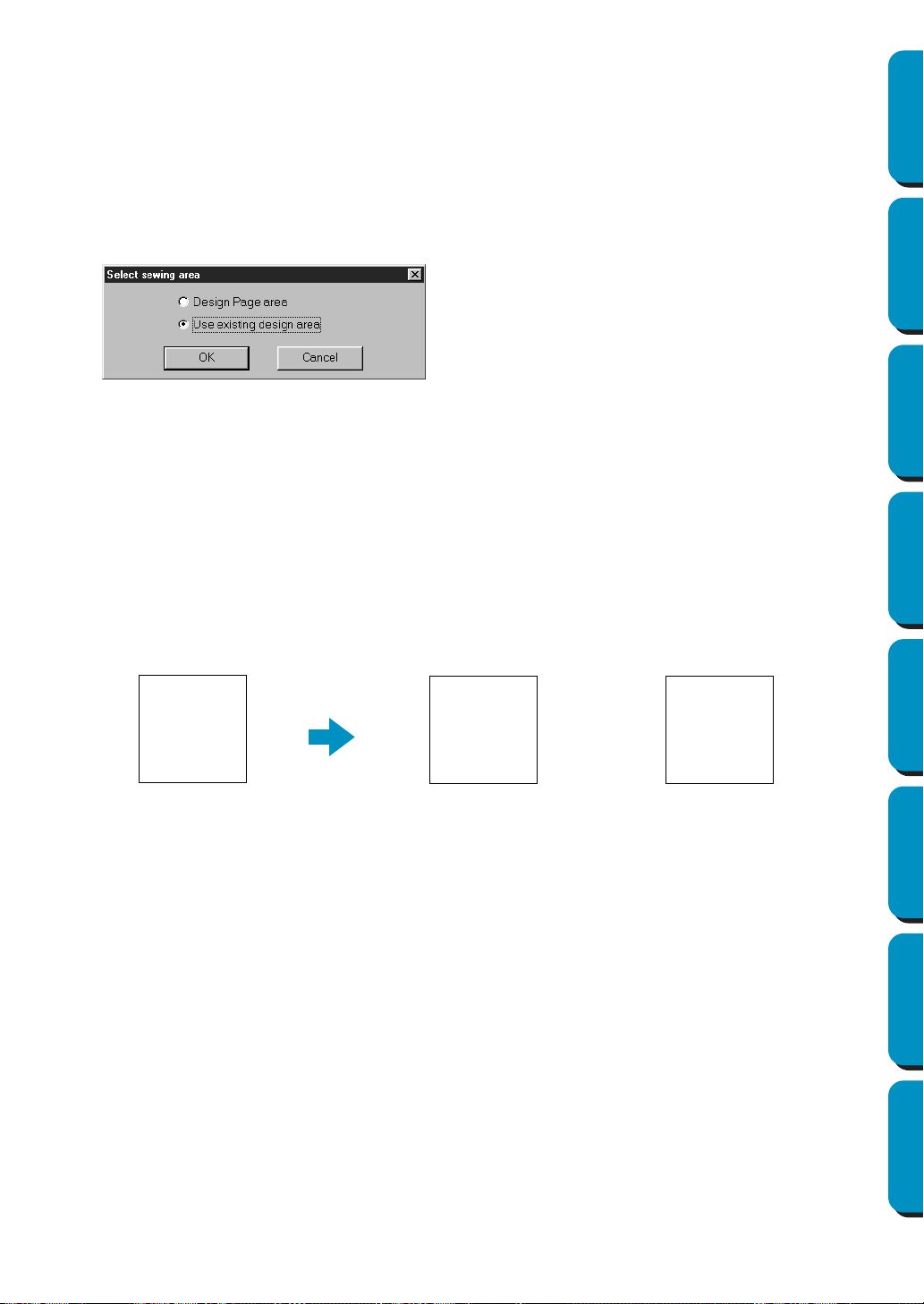
216
Contents Before Using Getting Started Design Center Layout & Editing
Programmable
Stitch Creator
Quick Reference Alphabetic Index
■ Select Sewing Area
Purpose: Sets the sewing area
Shortcut key: No shortcut key for this function
Toolbar: No button for this function
Operation:
1 Click Sew, then Select Sewing Area.
This dialog displays.
With
Design Page area, the patterns will be sewn so that the place where the needle is when you
start coincides with the center of your Design Page.
NOTE:
When Design Page area is selected, the dimension of the pattern matches the size of the Design
Page, therefore reducing the ability to move a pattern around the layout screen of your embroidery
machine.
With Use existing design area, the patterns will be sewn so that the place the needle is when you
start coincides with the center of the actual patterns.
NOTE:
When Use existing design area is selected, the actual pattern size is maintained, therefore allowing
greater mobility when using the layout function of your embroidery machine.
See also: “Design Page Property” on page 225
◆ Select Design Page area or Use existing
design area
.
◆ Click OK to confirm.
◆ Click Cancel to exit.
Design Page (on your screen) Sewing area = Use existing designSewing area = Design Page
A
A
A

217
Contents Before Using Getting Started Design Center Layout & Editing
Programmable
Stitch Creator
Quick Reference Alphabetic Index
■ Optimize hoop change
Purpose: Optimizes the sewing order of patterns in a Design Page for multi-position embroi-
dery frames (100 × 172 mm, 172 × 100 mm, 130 × 300 mm, or 300 × 130 mm)
Shortcut key: No shortcut key for this function
Toolbar: No button for this function
Operation:
1 Click Sew, then Optimize hoop change.
This setting can be turned on or off. A check mark appears when this setting is turned on; no
check mark is displayed when this setting is turned off.
NOTE:
Depending on the pattern, turning on the Optimize hoop change setting may reduce the number of
times that the embroidery frame installation position is changed. More importantly, it reduces the
chances of the embroidery not being sewn correctly or the fabric becoming wrinkled when the
embroidery frame installation position is changed too often.
When the
Optimize hoop change setting is turned
on:
The sewing order that you have set is optimized
to reduce the number of times that the embroi-
dery frame installation position is changed.
For the example shown at the right, the sewing
order is: a (pattern 1) → b (pattern 2) → a (pat-
terns 3 & 5) → c (patterns 4 & 6)
When the Optimize hoop change setting is turned
off:
Each pattern is sewn according to the sewing
order that you have set. Therefore, since the num-
ber of times for changing the embroidery frame
installation position is not optimized, it may be
changed more often than if it was optimized.
For the example shown at the right, the sewing
order is: a (pattern 1) → b (pattern 2) → a (pattern
3) → c (pattern 4) → a (pattern 5) → c (pattern 6)
a
b
c
4
2
1
3
5
6
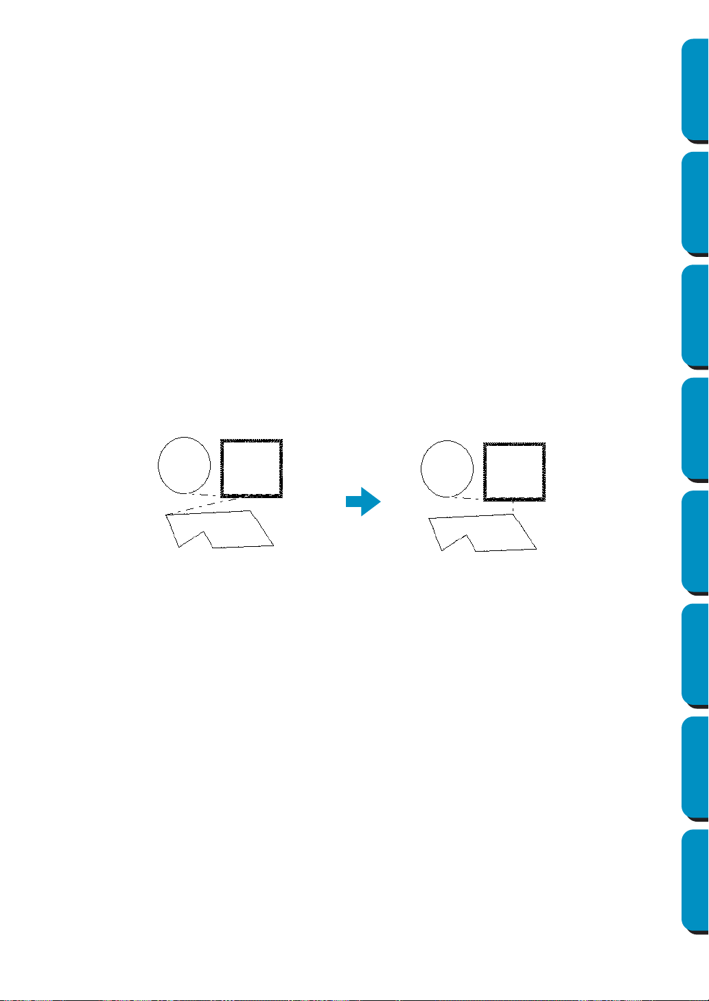
218
Contents Before Using Getting Started Design Center Layout & Editing
Programmable
Stitch Creator
Quick Reference Alphabetic Index
■ Optimize Entry/Exit points
Purpose: Optimizes the positions of the entry points and the exit points for the sewing data
Shortcut key: No shortcut key for this function
Toolbar: No button for this function
Operation:
1 Click Sew, then Optimize Entry/Exit points.
This setting can be turned on or off. A check mark appears when this setting is turned on; no
check mark is displayed when this setting is turned off.
When the
Optimize Entry/Exit points setting is turned on:
The entry points and exit points for the sewing data of connected objects with the same color are
optimized (connected with the shortest distance possible).
• Objects that can be optimized are data created with the Circle, Rectangle and Outline tools.
• When the Optimize Entry/Exit points setting is turned on, the entry point and the exit point cannot
be changed with the entry/exit point edit tool.
When the Optimize Entry/Exit points setting is turned off:
The entry points and exit points are not optimized. If the Optimize Entry/Exit points setting is
changed from on to off, the last entry point and exit point positions are maintained. In addition, the
positions of the entry points and the exit points can be manually changed with the entry/exit point
edit tool.
Optimize Entry/Exit points turned off
Optimize Entry/Exit points turned on
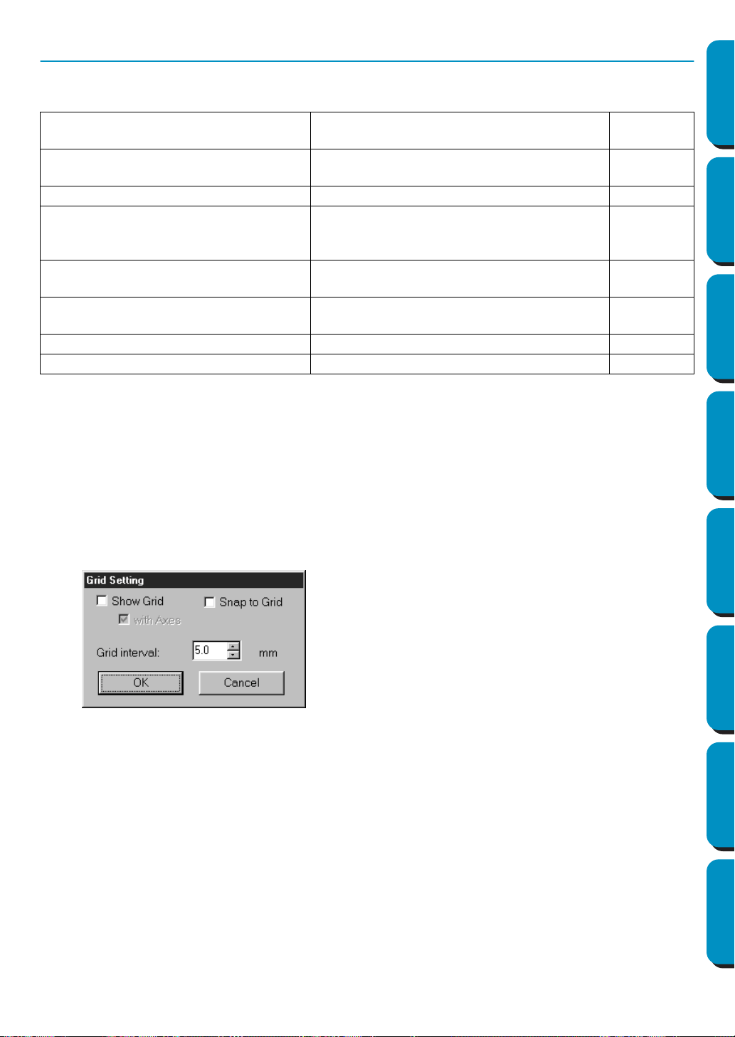
219
Contents Before Using Getting Started Design Center Layout & Editing
Programmable
Stitch Creator
Quick Reference Alphabetic Index
Display Menu
The Display menu lets you modify the appearance of the screen.
■ Grid Setup
Purpose: Controls the display and characteristics of the grid.
Shortcut key: No shortcut key for this function
Toolbar: No button for this function
Operation:
1 Click Display, then Grid Setup.
The Grid Setting dialog appears.
See also: “Select System Unit” on page 229
Grid Setup
Controls the display and characteristics of
the grid.
page 219
Preview
Specifies whether the patterns appear as
stitches or in the normal view.
page 220
Refresh Window Updates the screen. page 220
Realistic Preview
Displays a realistic image of how either
selected patterns or all patterns will look
after being embroidered.
page 220
Realistic Preview Attribute Setting
Sets the preview attributes for Realistic Pre-
view.
page 221
Stitch Simulator
Displays a simulation of the machine stitch-
ing.
page 221
Toolbar Turns the Toolbar on/off. page 222
Status Bar Turns the Status bar on/off. page 222
◆ Check
Snap to Grid when you want to use the
grid for aligning patterns or creating patterns
of the same size. The cursor will move by the
amount set in Grid Interval.
• The snap feature works whether or not the grid
is displayed.
◆ Check Show Grid to see the grid on your
Design Page.
◆ Type in the
Grid Interval to set both horizontal
and vertical steps of the grid.
Grid interval range: 1 - 10 mm (0.04 - 0.39 inch)
◆ Check with Axes to turn the horizontal and ver-
tical lines of the grid on.
• When the Show grid check box is checked and
the
with Axes check box is not checked, only the
intersection points of the grid will be displayed.
◆ Click OK to confirm.
◆ Click
Cancel to exit.
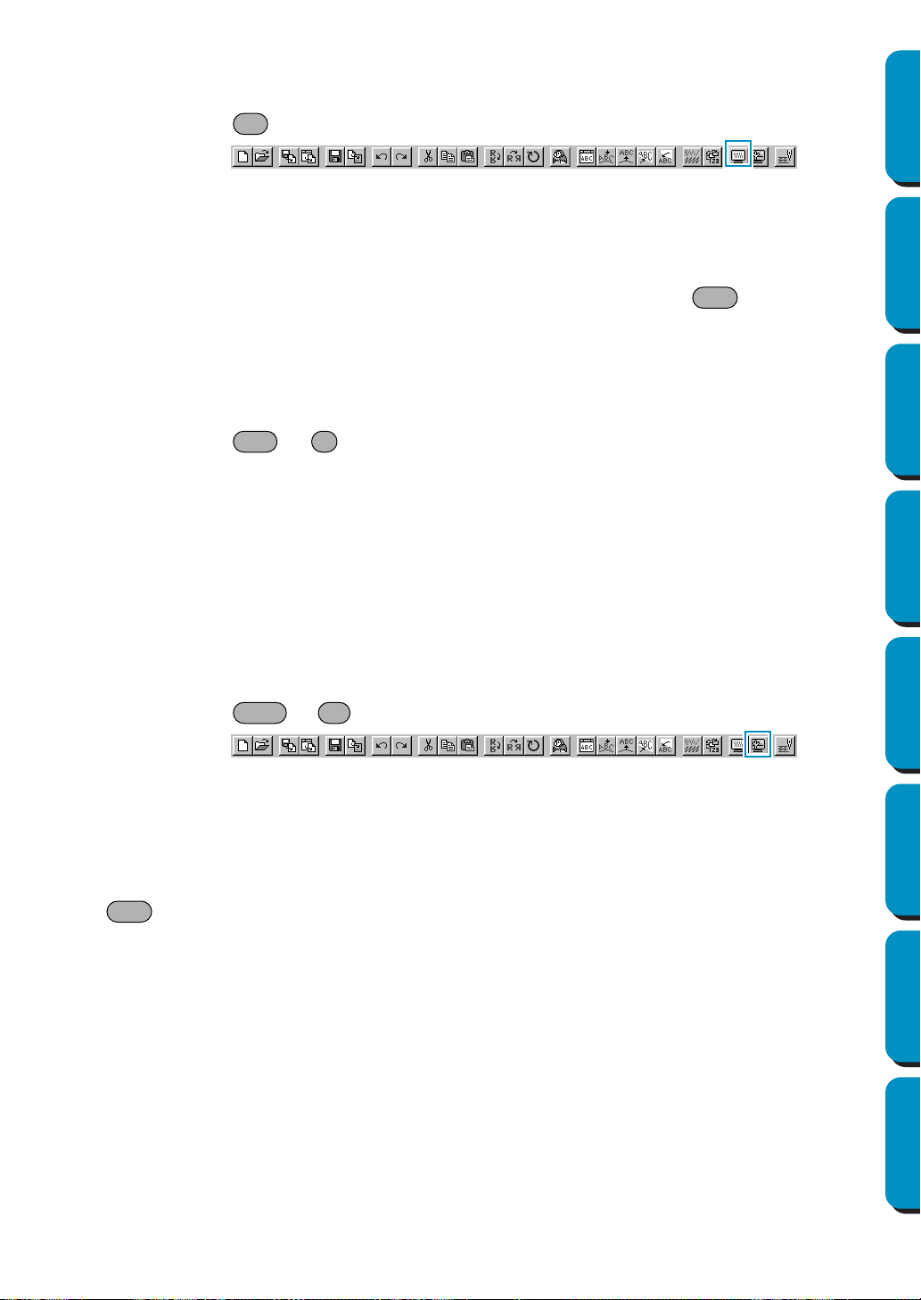
220
Contents Before Using Getting Started Design Center Layout & Editing
Programmable
Stitch Creator
Quick Reference Alphabetic Index
■ Preview
Purpose: Specifies whether the patterns appear as stitches or in the normal view.
Shortcut key:
Toolbar:
Operation:
1 Click Display, then Preview.
A preview of your embroidery patterns will appear.
Even while this preview is displayed, other editing operations can be performed.
2 To return to the normal view, click Display, then Preview again or press the key.
See also: “Sewing Order” on page 210
■ Refresh Window
Purpose: Updates the screen.
Shortcut key: +
Toolbar: No button for this function
Operation:
1 Click Display, then Refresh Window.
Use this function when the screen does not seem to respond correctly, for example, when residue
of a pattern remains on the screen after the pattern has been cut.
■ Realistic Preview
Purpose: Displays a realistic image of how either selected patterns or all patterns will look
after being embroidered.
Shortcut key: +
Toolbar:
Operation:
1 Click Display, then Realistic Preview.
The patterns on the Design Page are displayed realistically according to the settings in the Realis-
tic Preview Attribute Setting
dialog.
2 To return to the normal working screen, click Display, then Realistic Preview again or press the
key.
NOTE:
The Realistic Preview function cannot display a beautiful preview of the pattern if the monitor is set
to 256 colors or less. The monitor should be set to at least 16-bit High Color (65536 colors).
See also: “Realistic Preview Attribute Setting” on page 221
F9
Esc
Ctrl R
Shift F9
Esc

221
Contents Before Using Getting Started Design Center Layout & Editing
Programmable
Stitch Creator
Quick Reference Alphabetic Index
■ Realistic Preview Attribute Setting
Purpose: Sets the preview attributes for Realistic Preview.
Shortcut key: No shortcut key for this function
Toolbar: No button for this function
Operation:
1 Click Display, then Realistic Preview Attribute Setting.
The following dialog appears.
See also: “Realistic Preview” on page 220
■ Stitch Simulator
Purpose: Displays a simulation of the machine stitching.
Shortcut key: No shortcut key for this function
Toolbar:
Operation:
1 Click Display, then Stitch Simulator.
The following dialog appears and the embroidery data in the Design Page is cleared.
◆ Use Thread Width to set how wide the
thread will appear.
◆ Use Contrast to set the contrast.
◆ Use Brightness to set how bright the dis-
play is.
◆
Click Apply to display a Realistic Preview of
the patterns with the new settings.(When
Realistic Preview is displayed.)
Or, click OK to save the setting for the next
time it is displayed. (When Realistic Pre-
view is not displayed.)
◆ Click
Close or Cancel to exit.
◆ Click to begin the stitching simulation.
During the stitching simulation, this button
changes to a pause button ( ).
◆ Click to advance the simulation to the
beginning of the next color.
◆ Click to reverse the simulation to the
beginning of the previous color.
◆ Click to stop the simulation and return the
display to the previous view.
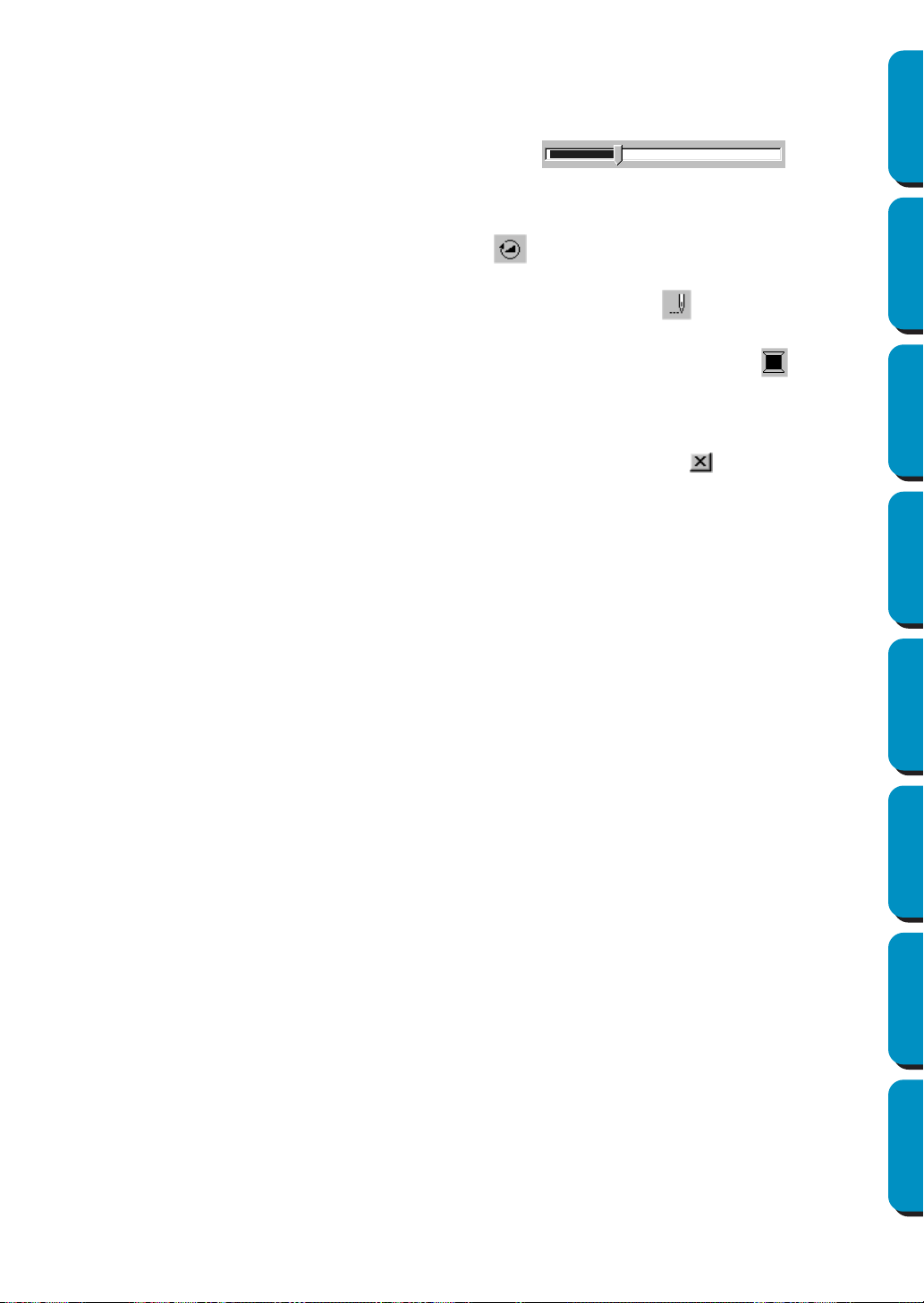
222
Contents Before Using Getting Started Design Center Layout & Editing
Programmable
Stitch Creator
Quick Reference Alphabetic Index
NOTE:
If a pattern is selected when this function is selected, only the selected pattern is drawn in the sim-
ulation.
■ Toolbar
Purpose: Turns the Toolbar on/off.
Shortcut key: No shortcut key for this function
Toolbar: No button for this function
Operation:
1 Click Display, then Toolbar.
The Toolbar will be toggled on/off.
See also: “Status Bar” below
■ Status Bar
Purpose: Turns the Status bar on/off.
Shortcut key: No shortcut key for this function
Toolbar: No button for this function
Operation:
1 Click Display, then Status bar.
The Status bar will be toggled on/off.
See also: “Toolbar” above
◆ The slider shows the current location in the
simulation. In addition, adjusting the slider can
change the position in the simulation.
◆ The simulation stitching speed can be
adjusted by dragging the slider indicated by
.
◆ The numbers beside indicate the number
of the stitch being drawn/the total number of
stitches, and the numbers beside indicate
the number of the color being drawn/the total
number of colors.
◆ To close the dialog, click in the upper-right
corner of the dialog.
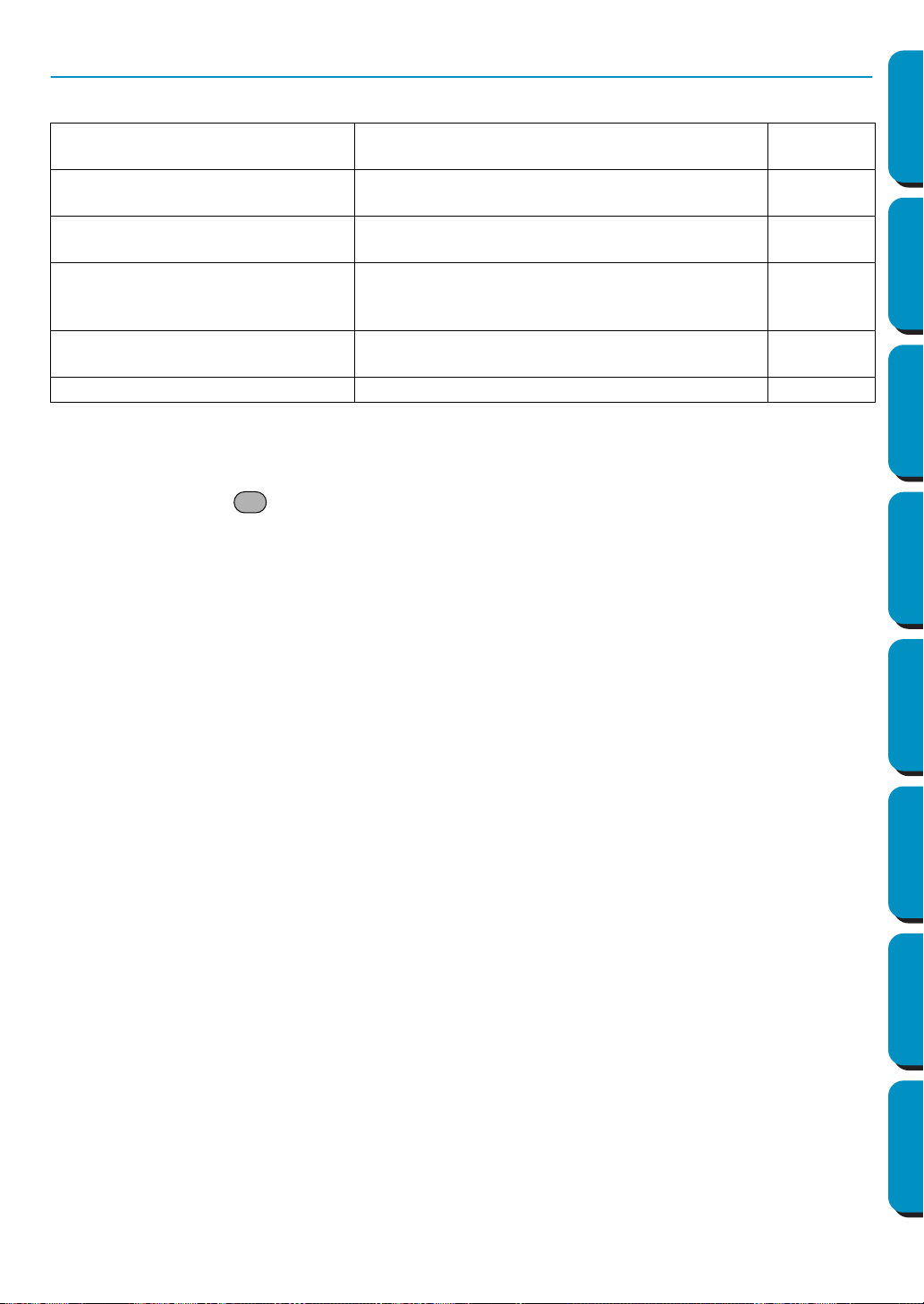
223
Contents Before Using Getting Started Design Center Layout & Editing
Programmable
Stitch Creator
Quick Reference Alphabetic Index
Option Menu
The Option menu provides additional options.
■ Design Center
Purpose: Starts Design Center and displays its window up front.
Shortcut key:
Toolbar: No button for this function
Operation:
1 Click Option, then Design Center.
Design Center starts if its window wasn’t open and if it was open, the window comes up front.
After creating a pattern with the Design Center Application, you can import it in Design Page of
Layout & Editing.
See also: “Import – from Design Center” on page 153
■ Programmable Stitch Creator
Purpose: Starts Programmable Stitch Creator and displays its window up front.
Shortcut key: No shortcut key for this function
Toolbar: No button for this function
Operation:
1 Click Option, then Programmable Stitch Creator.
Programmable Stitch Creator starts if its window wasn’t open and if it was open, the window
comes up front.
■ Design Property
Purpose: Opens a dialog containing sewing information for the selected pattern(s).
Shortcut key: No shortcut key for this function
Toolbar: No button for this function
Design Center
Starts Design Center and displays its window up
front.
page 223
Programmable Stitch Creator
Starts Programmable Stitch Creator and displays
its window up front.
page 223
Design Property
Opens a dialog containing sewing information for
the selected pattern(s).
page 223
Design Page Property
Allows you to change the size of the Design Page
and the color of the Design Page and the Design
Page background.
page 225
Edit User Thread Chart
Allows original thread charts to be created and
edited.
page 225
Select System Unit
Allows you to select the unit of length (mm or inch).
page 229
F5

224
Contents Before Using Getting Started Design Center Layout & Editing
Programmable
Stitch Creator
Quick Reference Alphabetic Index
Operation:
1 Click Option, then Design Property.
The
Design Property dialog displays.
This dialog allows you to quickly check the dimensions, the needle count, the color count and color order
of the selected pattern(s).
You can select and check the properties of individual objects composing your embroidery pattern.
If a Design Page for a multi-position embroidery frame (130 × 300 mm, 300 × 130
mm, 100 × 172 mm, or 172 × 100 mm) is selected:
If no object in the Design Page is selected, the following Design Property dialog displays.
When this dialog appears, the Design Page is automatically enlarged or shrunk to fit in the entire window.
The Previous button cannot be clicked when the design corresponding to the first embroidery installation
position is already displayed. In addition, the Next button cannot be clicked when the design correspond-
ing to the last embroidery installation position is already displayed.
NOTE:
If an object is larger than the embroidering area or if an object is positioned so that it does not
completely fit within an embroidering area, the error message “Please change the object size or
position.” is displayed instead of this dialog. After the object causing the error appears selected,
change its size or position. (If more than one object causes the error message to appear, the
objects will appear selected in the sewing order.)
◆ If the With Basic Color check box is selected,
the display can be switched with the machine’s
preset color names.
◆ Click Close to close the window.
◆ The first line of the dialog shows the position in
the embroidery frame installation order for the
currently displayed design.
• Only the designs that would be sewn at the
current position in the embroidery frame instal-
lation order appear in the Design Page. In
addition, the embroidering area for the current
frame installation position is outlined in red.
◆ Click Previous or Next to display information for
the designs at other positions in the embroi-
dery frame installation order.
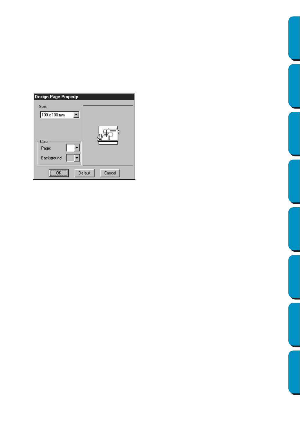
225
Contents Before Using Getting Started Design Center Layout & Editing
Programmable
Stitch Creator
Quick Reference Alphabetic Index
■ Design Page Property
Purpose: Allows you to change the size of the Design Page and the color of the Design
Page and the Design Page background.
Shortcut key: No shortcut key for this function
Toolbar: No button for this function
Operation:
1 Click Option, then Design Page Property.
The
Design Page Property dialog displays.
The Design Page sizes 130 × 300 mm, 300 × 130 mm, 100 × 172 mm, and 172 × 100 mm, indi-
cated by “*”, are used to embroider multi-position designs using a special embroidery frame
attached to the sewing machine at three installation positions. Check that you have the multi-posi-
tion embroidery frame and that these multi-position designs can be embroidered using your sew-
ing machine.
See also: “Select System Unit” on page 229
■ Edit User Thread Chart
Purpose: Allows original thread charts to be created and edited.
Shortcut key: No shortcut key for this function
Toolbar: No button for this function
Operation:
1 Click Option, then Edit User Thread Chart.
A dialog similar to the one shown below appears.
◆ Select the size by clicking the appropriate
radio button.
Select the Page color or the Background color
by clicking its selector arrow, then by clicking
the color.
• The preview area allows you to view the set-
ting changes. The sewing machine picture
shows the direction of the Design Page
(frame) on the machine.
◆ Click OK to confirm.
◆ Click
Default to go back to the default setting.
◆ Click
Cancel to exit.
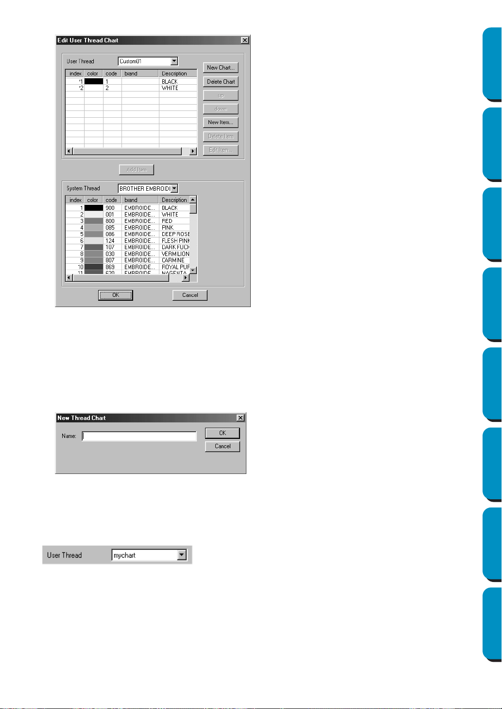
226
Contents Before Using Getting Started Design Center Layout & Editing
Programmable
Stitch Creator
Quick Reference Alphabetic Index
User thread charts can be created and edited to contain a list of threads that you use most often or
a list of all threads that you have. Thread data from system thread charts can be included or new
thread data can be added.
[Creating a New Thread Chart]
Click New Chart. The following dialog appears.
Type in the name of the chart, and then click OK to save the chart with the entered name.
The saved chart can be selected from the User Thread Chart list, then edited.
[Deleting a Chart]
From the User Thread Chart list, select the chart that you want to delete.
Click Delete Chart to delete the selected chart.
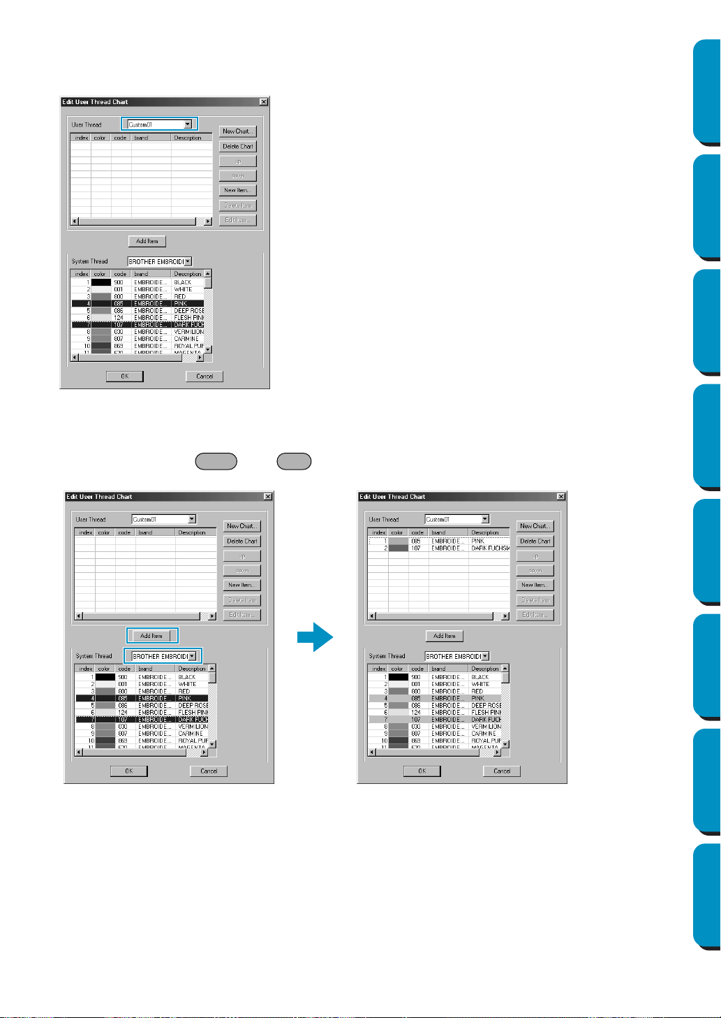
227
Contents Before Using Getting Started Design Center Layout & Editing
Programmable
Stitch Creator
Quick Reference Alphabetic Index
[Editing a Chart]
From the User Thread Chart list, select the chart that you want to edit.
If no chart is selected, the editing operation cannot be performed.
•Adding an item from a system thread chart
From the System Thread Chart list, select the brand of thread that you want to add.
From the list at the bottom of the dialog, click the thread item that you want to add. (To add multiple
items, hold down the and keys while selecting thread items.)
Click Add Item to add the selected items to the list in the user thread chart.
Shift Ctrl
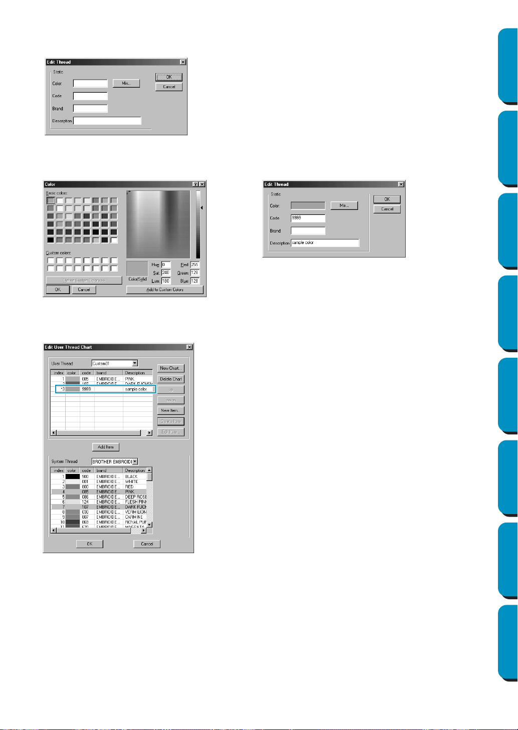
228
Contents Before Using Getting Started Design Center Layout & Editing
Programmable
Stitch Creator
Quick Reference Alphabetic Index
•Adding a new item
Click New Item. The following dialog appears.
To create a new color, click Mix. A dialog similar to the one shown below appears. Specify the color,
and then click OK to add the specified color to the previous dialog.
If necessary, type in the code, brand and description into the appropriate text boxes.
Only numbers can be entered for the code.
Click
OK to add the new item to the user thread chart.
An asterisk (*) appears in front of the index number of newly added items.
•Deleting an item
From the list for the user thread chart, select the item to be deleted, and then click
Delete Item to
delete the item from the user thread chart.
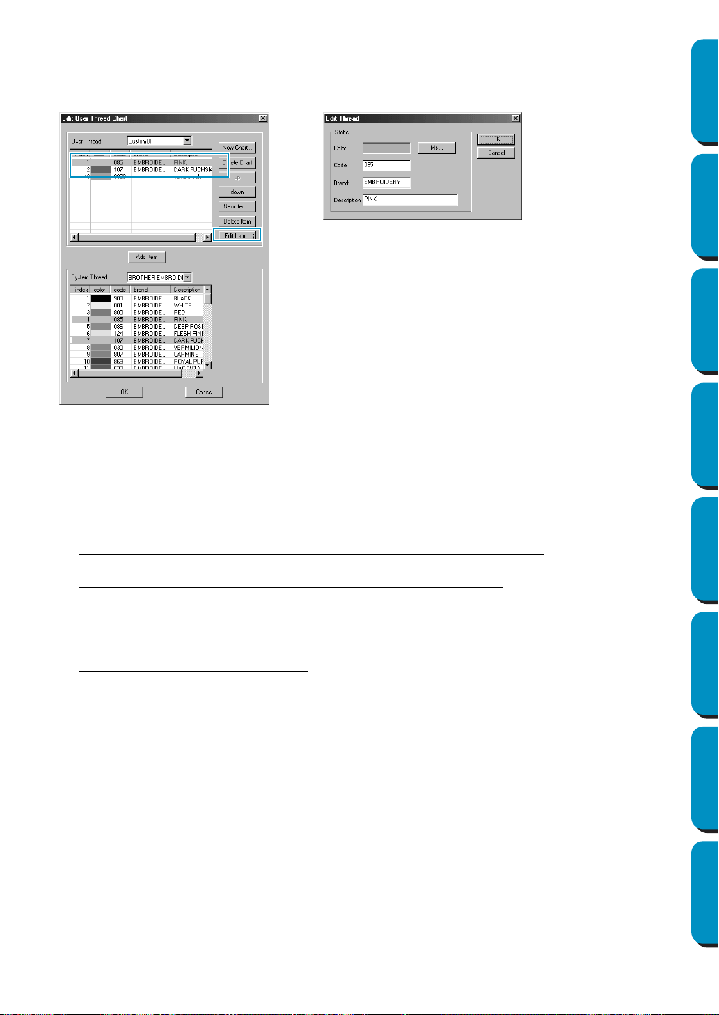
229
Contents Before Using Getting Started Design Center Layout & Editing
Programmable
Stitch Creator
Quick Reference Alphabetic Index
•Editing an item
An item registered in the list for a user thread chart can be edited to change the color or thread number.
From the list for the user thread chart, select the item to be edited, and then click Edit Item. The follow-
ing dialog appears. Edit the item details in the same way as adding an item.
As with newly added items, an asterisk (*) appears in front of the index number of edited items.
•Changing the order of items
From the list for the user thread chart, select the item to be moved, and then click up or down to
change the order of the item.
NOTE:
Thread colors in embroidery data created with this software may appear differently on the embroi-
dering machine. Refer to the following.
1.
Embroidering machines without a function for displaying color information
The specified thread information may not be displayed with some machines.
2. Embroidering machines with a function for displaying thread colors
Of the thread information specified in the embroidery data, only the thread colors are displayed
on the machine. However, the thread color name that are displayed are limited to the machine’s
preset thread color names. Therefore, use thread color names in the embroidery data that are
closest to the machine’s preset thread color names.
3. Machines with a thread color index
Some machines can display the thread information specified with this software. Of the thread
information specified in the embroidery data, those machines can display the brand name and
thread number in addition to the information described in 2 above.
However, for items edited or added by the user (items marked with an asterisk (*)), only the
thread number is displayed.
■ Select System Unit
Purpose: Allows you to select the unit of length (mm or inch).
Shortcut key: No shortcut key for this function
Toolbar: No button for this function
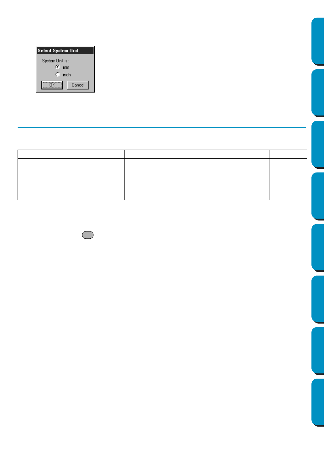
230
Contents Before Using Getting Started Design Center Layout & Editing
Programmable
Stitch Creator
Quick Reference Alphabetic Index
Operation:
1 Click Option, then Select System Unit.
This dialog will appear.
See also: “Grid Setup” on page 219, “Design Page Property” on page 225.
Help Menu
The Help menu gives you access to the on-screen help information system.
■ Contents
Purpose: Starts the on-screen help information for this application.
Shortcut key:
Toolbar: No button for this function
Operation:
1 Click Help, then Contents.
A table of contents of the on-screen help information displays.
2 Refer to your Windows manual for the next operation.
See also: “About Layout & Editing” on page 231
■ Customer support
Purpose: Opens the FAQ (Frequently Asked Questions) page in this company’s homepage.
Shortcut key: No shortcut key for this function
Toolbar: No button for this function
Operation:
1 Click Help, then Customer support from the menu.
2 The browser installed in the computer will start, and open the FAQ page of this company’s homep-
age.
NOTE:
This function cannot be used if there is no internet browser correctly installed in the computer.
◆ Select the unit (mm or inch).
◆ Click
OK to confirm.
◆ Click Cancel to exit.
Contents
Starts the on-screen help information for this application.
page 230
Customer support
Opens the FAQ (Frequently Asked Questions)
page in this company’s homepage.
page 230
Online Registration
Displays the online registration page from our
Web site.
page 231
About Layout & Editing
Gives information about the version of this application.
page 231
F1

231
Contents Before Using Getting Started Design Center Layout & Editing
Programmable
Stitch Creator
Quick Reference Alphabetic Index
■ Online Registration
Purpose: Displays the online registration page from our Web site.
Shortcut key: No shortcut key for this function
Toolbar: No button for this function
Operation:
1 Click Help, then Online Registration from the menu.
2 The installed browser is started and the online registration page is opened from our Web site.
NOTE:
This function only works if the Internet browser is correctly installed and the Internet connection
environment is established.
*Online registration is not possible in certain countries and regions.
■ About Layout & Editing
Purpose: Gives information about the version of this application.
Shortcut key: No shortcut key for this function
Toolbar: No button for this function
Operation:
1 Click Help, then About Layout & Editing.
A dialog will display.
2 Click OK to remove it.
See also: “Contents” on page 230

232
Contents Before Using Getting Started Design Center Layout & Editing
Programmable
Stitch Creator
Quick Reference Alphabetic Index
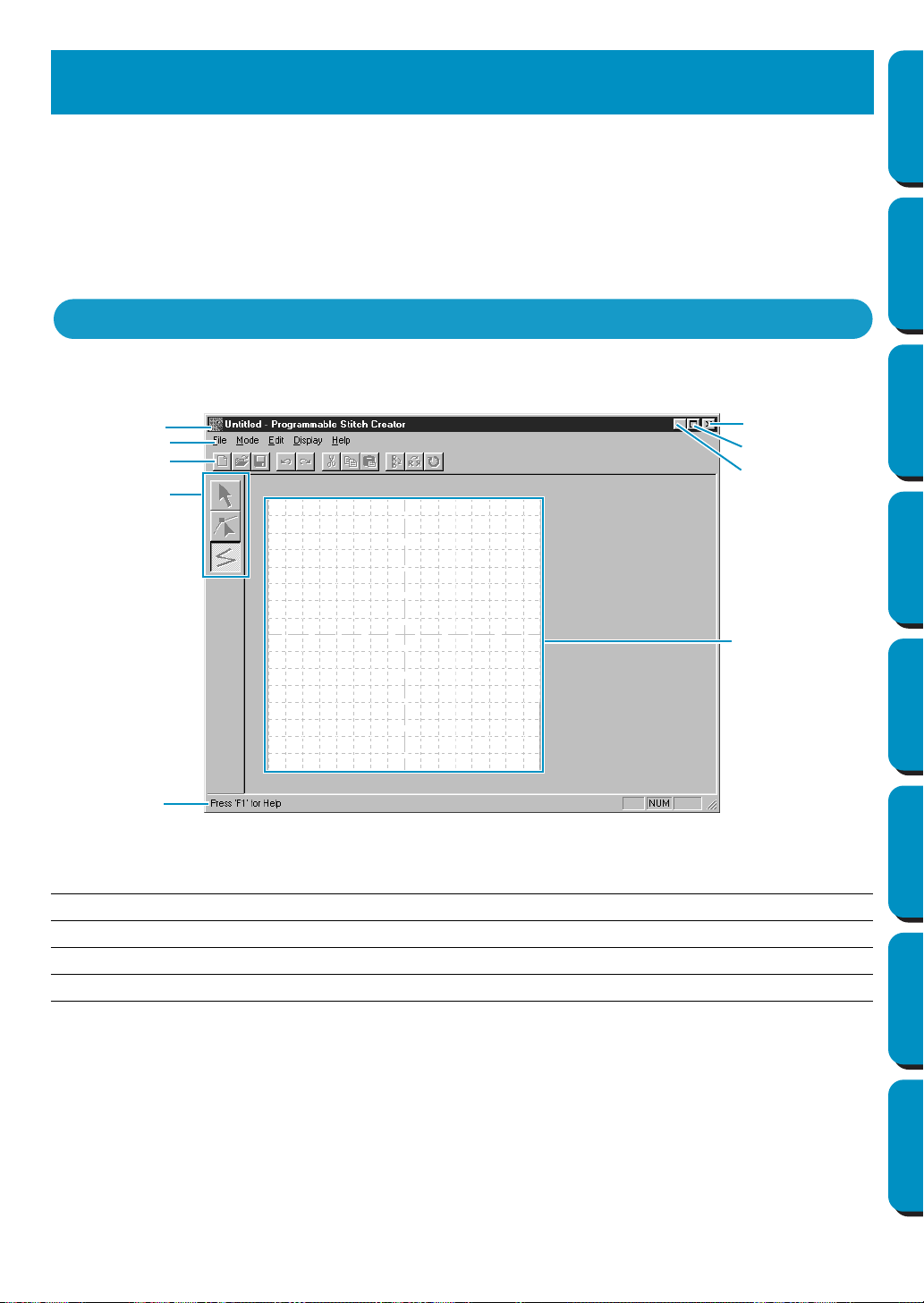
233
Contents Before Using Getting Started Design Center Layout & Editing
Programmable
Stitch Creator
Quick Reference Alphabetic Index
This application allows you to design your own fill stitch patterns, which you can set as sewing attributes
to enclosed regions of patterns, both in Design Center and Layout & Editing. The fill stitch patterns fill the
regions in a tile-like manner, resulting in particularly decorative embroidery patterns. You may create your
own fill stitch patterns or use the many stitches delivered with this application with or without editing
them. This application also allows you to design patterns for motif sewing. You can use Layout & Editing
to apply line stitch or fill stitch sewing attributes, or you can use Design Center to apply fill stitch attributes
to the motif pattern.
Menu bar Gives access to the functions.
Toolbar Shortcut for the menu functions.
Tool box Used to select and create fill stitch patterns.
Status bar Provides short information.
Programmable Stitch Creator
The Screen
Menu bar
Toolbar
Tool box
Work area
Status bar
Title bar
Maximize button
Minimize button
Close button
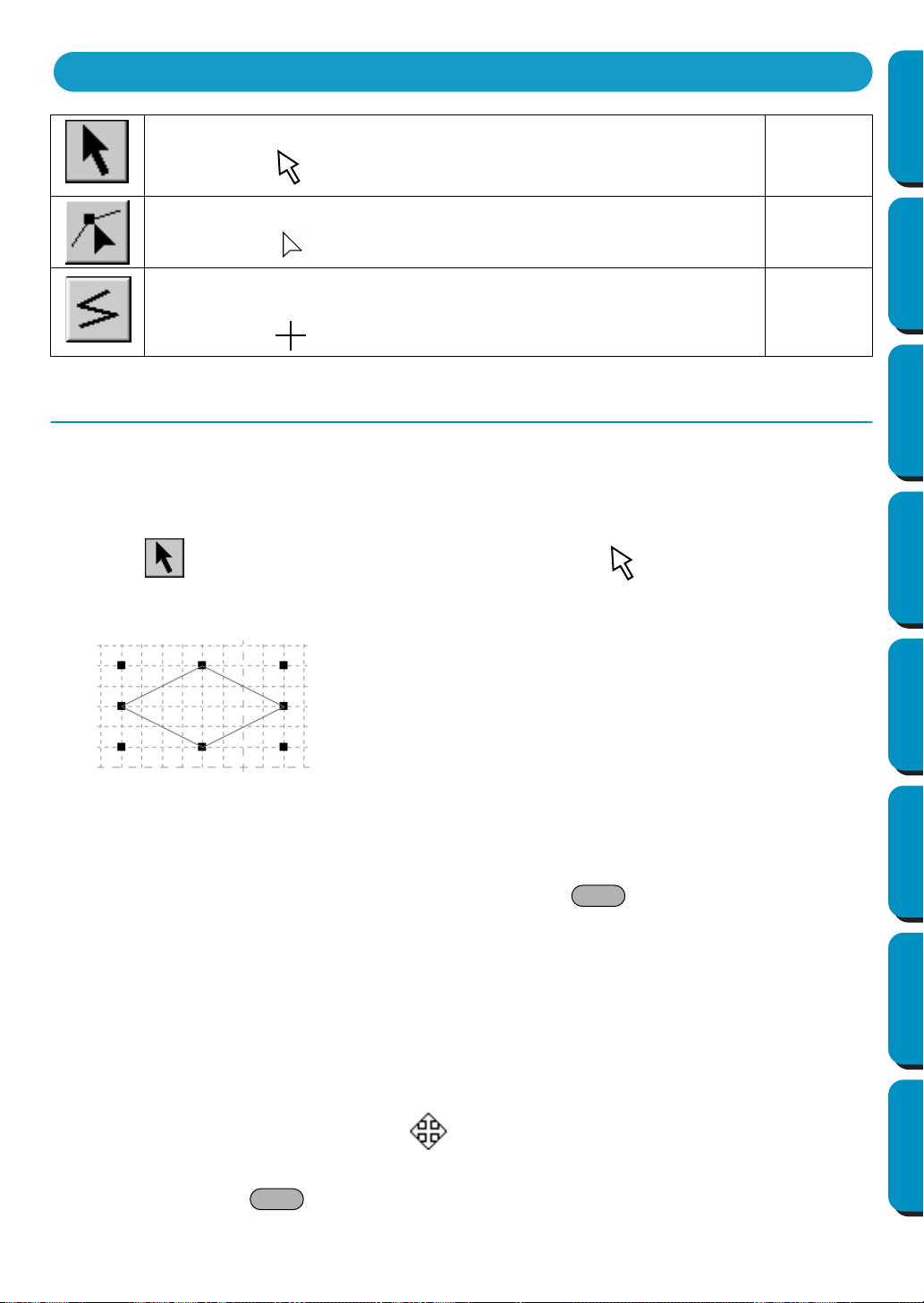
234
Contents Before Using Getting Started Design Center Layout & Editing
Programmable
Stitch Creator
Quick Reference Alphabetic Index
Selection Mode
The cursor selection mode is used to select one or more lines. Once a line is selected, you can move it,
scale it, and change its direction by rotating it or inverting it.
■ Selecting lines
1 Click on the Tool Box. The shape of the cursor changes to .
2 Click the line that you want to select.
You know that the line is selected when handles are displayed.
NOTE:
A pattern will not be selected if you do not click on a part of it.
3 To deselect the line, select another one, click on an empty space or click another button of the Tool
Box.
4 To select an additional line, click that line while holding the key down.
NOTE:
You can also select lines by dragging the cursor across the Work Area. As you drag, a dotted rect-
angle appears. When you release the mouse button, all lines that are completely contained in that
rectangle will be selected.
If other lines that you did not want selected are selected, click on an empty space to deselect all
lines, and then start again.
■ Moving lines
1
Move the cursor over a selected pattern or group of selected patterns.
The shape of the cursor will change to .
2 You can now drag the pattern to another location.
Holding down the key while dragging the line moves the line horizontally or vertically.
Sets the cursor in select mode.
Cursor shape:
page 234
Sets the cursor in point edit mode.
Cursor shape:
page 235
Sets the cursor in line drawing mode. When you start the application, the
drawing mode is active by default.
Cursor shape: with a miniature of the tool button
page 237
Using the Tool Box
Shift
Shift
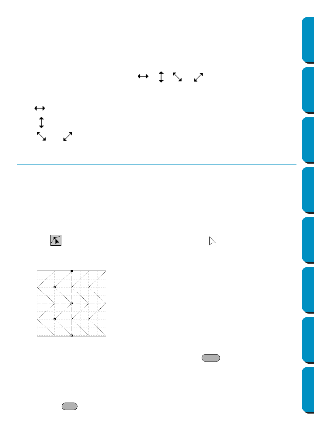
235
Contents Before Using Getting Started Design Center Layout & Editing
Programmable
Stitch Creator
Quick Reference Alphabetic Index
NOTE:
Pressing the up, down, left, or right arrow keys will move the line one grid space each time the key
is pressed. If the grid is not displayed, the line moves the distance of the smallest grid space in the
direction shown on the key.
■ Scaling lines
1
Move the cursor over one of the handles of a selected line or group of selected lines.
The shape of the cursor will change to , , or , depending on the handle the cur-
sor is on.
2 Drag the handle in the direction of the arrow to scale the pattern.
is for scaling the width.
is for scaling the height.
and are for scaling both dimensions at the same time.
Point Edit Mode
The point edit mode allows you to move, insert and delete points of a stitch pattern.
The points you move or insert are positioned at the intersection of the horizontal and vertical lines of the
grid. So, regardless on where you drag a point to or insert a point on the line, it will automatically position
itself at the nearest intersection.
Depending on the stitch you want to create, you may need to select a different working grid.
For more information on the grids and on how to select them, refer to “Grid” on page 248.
■ Moving points
1
Click on the Tool Box. The shape of the cursor changes to .
2 Click the broken line that you want to edit. You can only select one broken line at a time.
The existing points of the selected broken line are marked with small empty squares.
3 Click the point that you want to move.
To select an additional point, click that point while holding the key down. You may also
click and drag the cursor over the area which includes all the points that you want to select. When
you release the mouse, the points included in that area are selected.
The selected points are marked by filled squares.
NOTE:
If you click on the line instead of a square, a new point is inserted.
Pressing +
→
or
←
will move the selection to the previous or next point in a line.
Shift
Ctrl

236
Contents Before Using Getting Started Design Center Layout & Editing
Programmable
Stitch Creator
Quick Reference Alphabetic Index
4 Drag the cursor to a new position. All the selected points move in the same direction.
Holding down the key while dragging the point moves the point horizontally or vertically.
NOTE:
Pressing the up, down, left, or right arrow keys will move the point one grid space each time the
key is pressed. If the grid is not displayed, the point moves the distance of the smallest grid space
in the direction shown on the key.
When in Motif Mode, if you move the start point (blue rectangle) or the end point (red rectangle) up
or down, the other point will automatically move up or down. Also, the start and end points can not
be moved closer than a certain fixed distance.
■ Inserting points
1
Click on the Tool Box. The shape of the cursor changes to .
2 Click the broken line that you want to edit. You can only select one broken line at a time.
The existing points of the selected broken line are marked with small empty squares.
3 Click where you want to insert a new point on the broken line.
A new point appears, marked by a filled black square. The new point can be edited.
■ Deleting points
1
Click on the Tool Box. The shape of the cursor changes to when you move it over the
Work page.
2 Click the broken line that you want to edit. You can only select one broken line at a time.
The existing points of the broken line are marked with small empty squares.
3 Click the point that you want to delete.
To select an additional point, click that point while holding the key down.
The selected points are marked by filled squares.
4 Press the key to remove the selected points from the outline.
If the point is composed of a single line, the line is deleted.
NOTE:
When in Motif Mode, the start point (blue rectangle) and end point (red rectangle) can not be deleted.
Shift
Shift
Delete
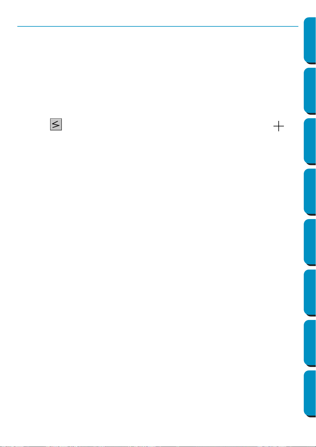
237
Contents Before Using Getting Started Design Center Layout & Editing
Programmable
Stitch Creator
Quick Reference Alphabetic Index
Line Drawing Mode
The line drawing mode allows you to draw broken lines to create your stitch pattern. A broken line is
made of one or more contiguous straight lines, the ending point of a straight line being the starting point
of the next one.
The horizontal and vertical lines that you draw on the work area always follow the grid. The points you
create by clicking the mouse are inserted at the intersection of the horizontal and vertical lines of the
grid, enabling you to draw diagonal lines as well. So, regardless of where you click, a point will automati-
cally be inserted at the nearest intersection.
Depending on the stitch pattern you want to draw, you may need to select a different working grid.
For more information on the grids and on how to select them, refer to “Grid” on page 248.
■ Drawing a broken line
1
Click on the Tool Box. When you move it over the Work page, the cursor changes to and
is displayed together with a small image of the tool button.
2 Move the mouse to the starting point of your broken line and click.
3 Move the mouse to the ending point of the first straight line and click again.
NOTE:
You can always remove the last-entered point by clicking the mouse’s right button.
4 Repeat until you arrive at the last end point. At that point double-click.
Repeat the whole procedure if you want to include other broken lines in a stitch pattern.
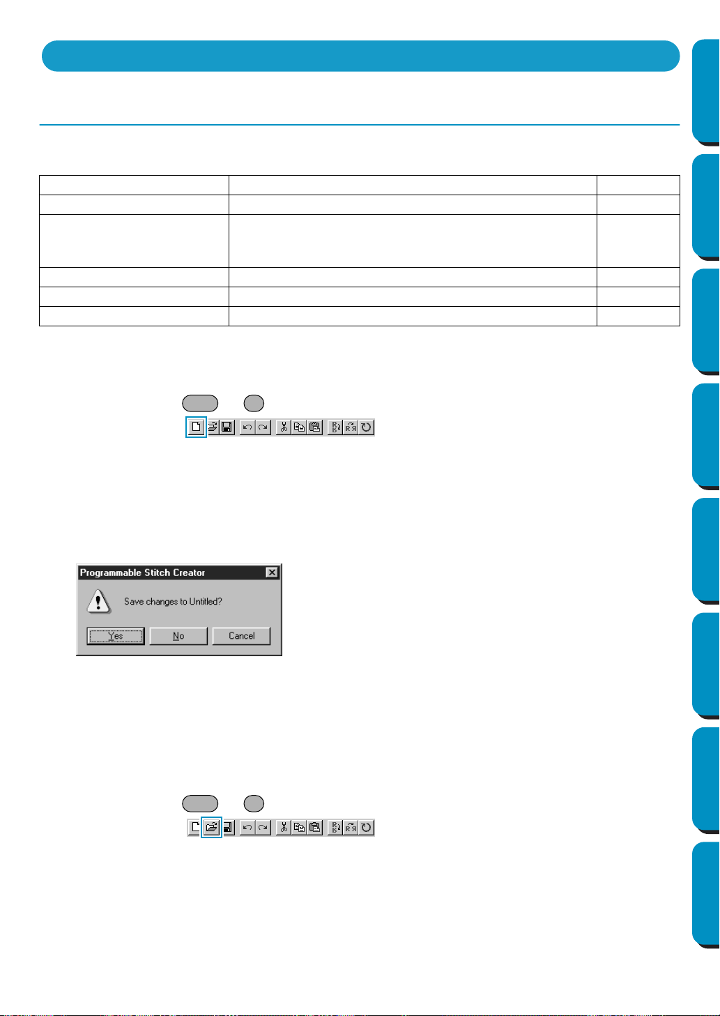
238
Contents Before Using Getting Started Design Center Layout & Editing
Programmable
Stitch Creator
Quick Reference Alphabetic Index
File Menu
The File menu allows you to execute commands regarding the files, such as opening and saving.
■ New
Purpose: Creates a new blank work area.
Shortcut key: +
Toolbar:
Operation:
1 Click File, then New.
If the current work area is not edited, a new blank work area appears immediately.
2 If the current work area is edited, you will be asked whether you want to save the changes, for
example:
A new blank work area appears.
See also: “Open”, “Save” and “Save As” in this section
■ Open
Purpose: Opens a previously saved programmable stitch file.
Shortcut key: +
Toolbar:
New Creates a new blank work area. page 238
Open Opens a previously saved programmable stitch file. page 238
Template Open
Opens a background image file that can be used as a
guide to draw a new pattern for Programmable Fill and
Motif.
page 240
Save Saves your work area on the disk. page 240
Save As Saves the current stitch pattern under a new file name. page 241
Exit Exits the application. page 241
◆ Click Yes to save the work area first.
◆ Click
No to abandon the work area.
◆ Click Cancel to do anything else (for exam-
ple, modify the current work area or saving
it with another file name).
Using the Menu Bar
Ctrl N
Ctrl O
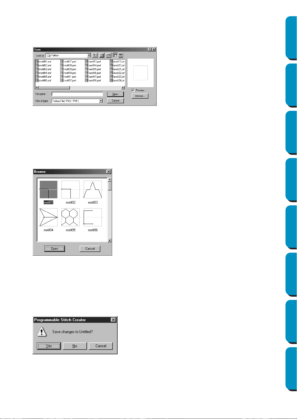
239
Contents Before Using Getting Started Design Center Layout & Editing
Programmable
Stitch Creator
Quick Reference Alphabetic Index
Operation:
1 Click File, then Open.
A
Open dialog similar to this will display.
2 When you click Browse, the Browse dialog opens.
3 The selected file opens immediately if your current work area is not edited.
If the current work area is edited, you will be asked whether you want to save the changes.
4 The edited stitch pattern is now saved and the selected file opens.
See also: “New” on page 238, “Save” on page 240, and “Save As” on page 241
◆ Select the drive, the folder and the file
name.
• Be sure the folder you select contains
pas or pmf files.
• If the Preview check box is checked, the
content of the selected file displays in
the preview window.
◆ Click
Open or double-click the file name
to open the file in the work area.
◆ Click Browse to preview all the available
pas or pmf files in the selected folder.
◆ Click Cancel to exit.
◆ Browse through the files with the help
of the scroll bar.
A green → in the middle of the pattern
display area shows that this is data for
Motif (
*.pmf). Otherwise, the data is for
Programmable Fill (*.pas).
◆ Select a stitch pattern by clicking on it.
The selected pattern is highlighted.
◆ Double-click the selected pattern or
click Open to open the file and to close
both the Open and the Browse dialogs.
The mode will automatically change to
match the selected pattern (pas or
pmf).
◆ Click
Cancel to go back to the Open dia-
log.
◆ Click Yes to save the work area first.
◆ Click No to abandon the work area.
◆ Click Cancel to do anything else (for
example, modifying the current work area
or saving it with another file name).
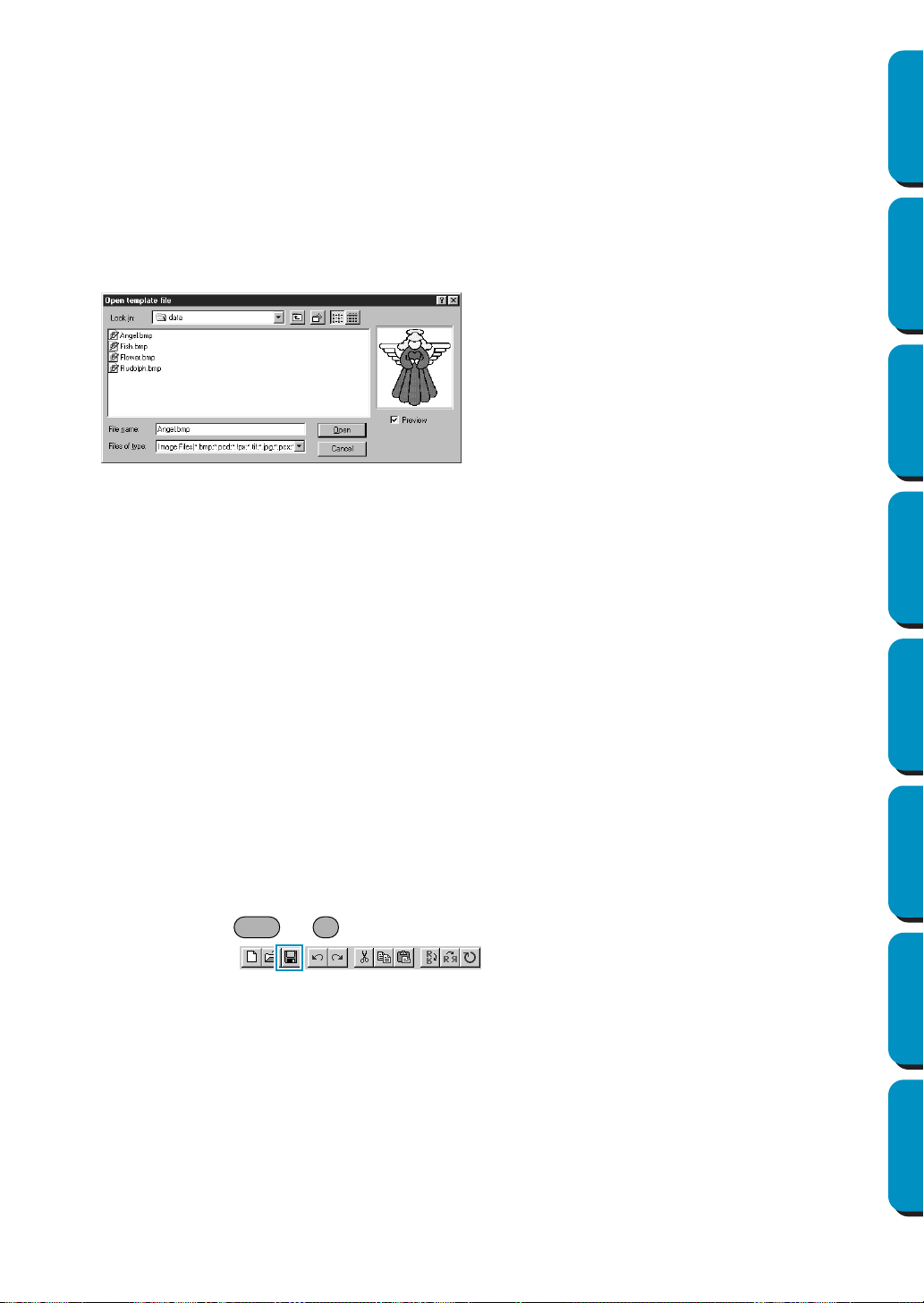
240
Contents Before Using Getting Started Design Center Layout & Editing
Programmable
Stitch Creator
Quick Reference Alphabetic Index
■ Template Open
Purpose: Opens a background image file that can be used as a guide to draw a new pattern
for Programmable Fill and Motif.
Shortcut key: No shortcut key for this function
Toolbar: No button for this function
Operation:
1 Click File, then Template Open.
An Open Template dialog similar to this will display.
See also: “Template-On, Faded, Off” on page 249
■ Save
Purpose: Saves your work area on the disk.
Shortcut key: +
Toolbar:
Operation:
1 Click File, then Save.
If the file already exists on the disk (the file has been saved at least once), the file is saved imme-
diately.
2 If the file name is still Untitled, if it is one of the “Read Only” pas or pmf files which come with this
application or if, for any other reason, the file cannot be found on the disk, the application automat-
ically switches to Save As.
See also: “Save As” on page 241
◆ Select the drive, the folder and the file
name.
• If the Preview check box is checked, the
content of the selected file displays in the
Preview window.
◆ Click
Open to open the file. The following
file formats can be opened:
Windows BMP (
*.bmp), Exif (*.tif, .jpg),
ZsoftPCX (.pcx), Windows Meta File
(
*.wmf), Portable Network Graphics
(*.png), Encapsulated PostScript (*.eps),
Kodak PhotoCD (
*.pcd), FlashPix (*.fpx).
NOTE:
For
pcd and fpx files that are saved on
many pages, only the first page can be
opened.
Tif files that have used LZW
compression can not be opened.
• Double-clicking the file name will also
open the file and close the dialog.
◆ Click Cancel if you want to exit the func-
tion.
Ctrl S
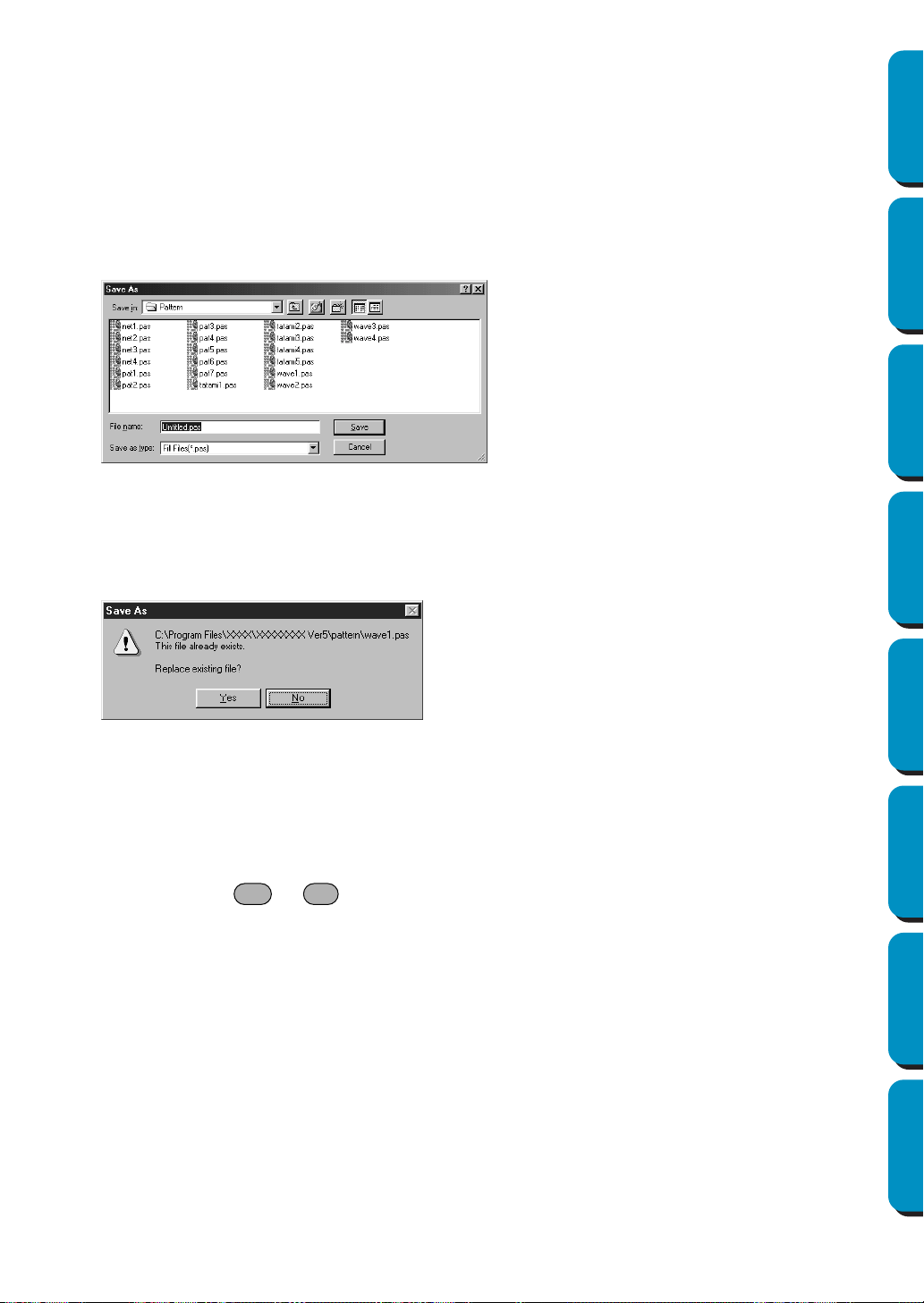
241
Contents Before Using Getting Started Design Center Layout & Editing
Programmable
Stitch Creator
Quick Reference Alphabetic Index
■ Save As
Purpose: Saves the current stitch pattern under a new file name.
Shortcut key: No shortcut key for this function
Toolbar: No button for this function
Operation:
1 Click File, then Save As.
A
Save As dialog similar to this will display.
2 If the new file name already exists, this dialog will appear.
See also: “Save” on page 240
■ Exit
Purpose: Exits the application.
Shortcut key: +
Toolbar: No button for this function
Operation:
1 Click File, then Exit.
If the current stitch pattern is not edited, the application closes immediately.
2 If the current stitch pattern is edited, you will be asked whether you want to save the changes.
See also: “Save” on page 240 and “Save As” above
◆ Select the drive, the folder and type the
file name.
• The file extension is automatically set
to match the Mode setting.
When Mode = Fill: *.pas
When Mode = Motif: *.pmf
◆ Click
Save to save.
◆ Click
Cancel to exit.
◆ Click
Yes to overwrite.
◆ Click
No if you do not want to overwrite
the existing file.
Alt F4

242
Contents Before Using Getting Started Design Center Layout & Editing
Programmable
Stitch Creator
Quick Reference Alphabetic Index
Mode Menu
You can use Programmable Stitch Creator to create patterns for Programmable Fill, and patterns for
Motif Fill or Motif Line. However, the method and Work Area are different for each. Use this mode
menu to make the setting for which pattern you will create.
Purpose: Changes the Mode for creating data.
Shortcut key: No shortcut key for this function.
Toolbar: No button for this function
Operation:
1 From the menu, click Mode, then select the heading that matches the pattern you want to create.
◆ Click Fill: the mode changes to create a pattern for Programmable Fill.
◆ Click Motif: the mode changes to create a pattern for Motif.
2 If the current work area is edited, you will be asked whether you want to save the changes, for
example:
Fill Mode
In Fill Mode, you can make a pattern out of one line or many lines.
In the tool box, there is a selection mode tool, a point edit mode tool, and a line drawing mode tool.
Using these tools, you can freely input and edit lines in the Work Area to create your pattern.
The sewing method for Programmable Fill is different from the regular Fill, where the thread is con-
stantly sewn in a set direction. Instead, the pattern will be sewn in such a way that the needle drops
directly over the created pattern.
◆ Click Yes to save the work area Page
first.
◆ Click
No to abandon the work area.
◆ Click
Cancel to do anything else (for
example, modify the current Design
Page or saving it with another file
name).
(Example of a pattern)
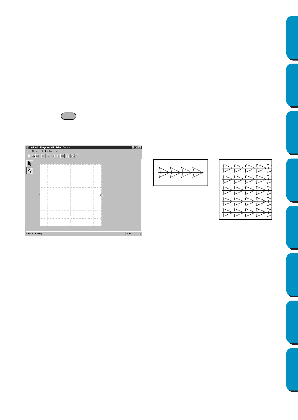
243
Contents Before Using Getting Started Design Center Layout & Editing
Programmable
Stitch Creator
Quick Reference Alphabetic Index
Motif Mode
In Motif Mode, you can create outline patterns efficiently using just one line.
In the center of the Work Area, a green arrow is displayed, showing the direction that the pattern
(stitch) will be sewn.
Also, in the center of the left edge of the box, there is blue rectangle, that shows the start point. In the
center of the right edge of the screen there is a red rectangle that shows the end point. These points
are connected by a line.
The selection tool and the point edit tool are in the tool box. Using the line already shown, you can
create a pattern by inserting points, moving, or editing the line in other ways.
You can not delete the start or end points. Also, the points must be in the same up/down position, so
if you move one point up or down, the other point will automatically move the same.
The sewing method for these patterns is done with the efficiency of outline patterns, like created pat-
terns.
(You can use + →, ← to check the order of the points.)
Also, you can set these patterns to be sewn for Line sewing or Region sewing. (In Design Center,
Region sewing only.)
(Example of a pattern)
Line sewing Region sewing
Ctrl
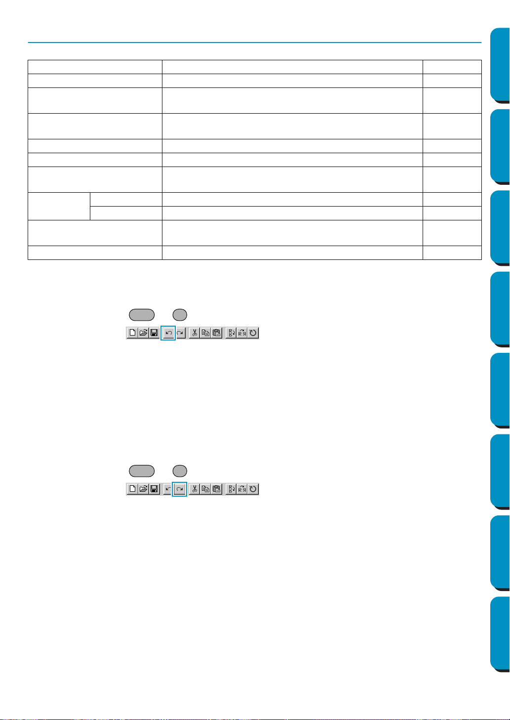
244
Contents Before Using Getting Started Design Center Layout & Editing
Programmable
Stitch Creator
Quick Reference Alphabetic Index
Edit Menu
■ Undo
Purpose: Undoes the last operation.
Shortcut key: +
Toolbar:
Operation:
1 Click Edit, then Undo.
The last operation is automatically undone. For example, if you have mistakenly deleted a line, this
function will make it reappear.
See also: “Redo” below
■ Redo
Purpose: Cancels the effect of the last Undo.
Shortcut key: +
Toolbar:
Operation:
1 Click Edit, then Redo.
The effect of the last
Undo is canceled. For example, if you have used Undo just after drawing a
line, the line is deleted. Using Redo will make the line reappear.
See also: “Undo” above
Undo Undoes the last operation. page 244
Redo Cancels the effect of the last Undo. page 244
Cut
Removes the selected line(s) from the screen while sav-
ing a copy in the clipboard.
page 245
Copy
Saves the selected line(s) in the clipboard without remov-
ing them from the screen.
page 245
Duplicate Makes a copy of the selected line(s). page 245
Paste Pastes the lines of the clipboard on the screen. page 245
Delete
Removes the selected line(s) from the screen without
saving them in the clipboard.
page 246
Mirror
Horizontal Flips the selected line(s) up/down. page 246
Vertical Flips the selected line(s) left/right. page 246
Rotate
Allows you to manually rotate the selected line(s) by an
arbitrary angle.
page 246
Select All Selects all the patterns. page 247
Ctrl Z
Ctrl A
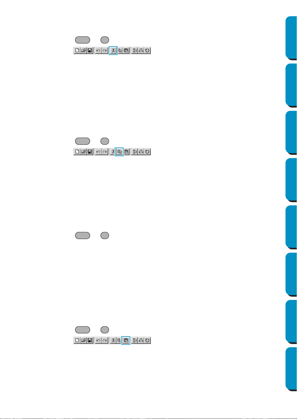
245
Contents Before Using Getting Started Design Center Layout & Editing
Programmable
Stitch Creator
Quick Reference Alphabetic Index
■ Cut
Purpose: Removes the selected line(s) from the screen while saving a copy in the clipboard.
Shortcut key: +
Toolbar:
Operation:
1 Select one or more lines.
2 Click Edit, then Cut.
The selected lines disappear. Since they are saved in the clipboard, you can paste them back
using
Edit - Paste.
See also: “Copy”, “Paste” below, “Delete” on page 246
■ Copy
Purpose: Saves the selected line(s) in the clipboard without removing them from the screen.
Shortcut key: +
Toolbar:
Operation:
1 Select one or more lines.
2 Click Edit, then Copy.
The patterns are copied into the clipboard and are ready to be pasted.
See also: “Cut” above, “Duplicate” and “Paste” below
■ Duplicate
Purpose: Makes a copy of the selected line(s).
Shortcut key: +
Toolbar: No button for this function
Operation:
1 Select one or more lines.
2 Click Edit, then Duplicate.
A copy of the lines appears on the screen.
See also: “Copy” above and “Paste” below
■ Paste
Purpose: Pastes the lines of the clipboard on the screen.
Shortcut key: +
Toolbar:
Operation:
1 Click Edit, then Paste.
The lines saved in the clipboard (using Cut or Copy) are pasted on the screen.
See also: “Cut”, “Copy” and “Duplicate” above
Ctrl X
Ctrl C
Ctrl D
Ctrl V
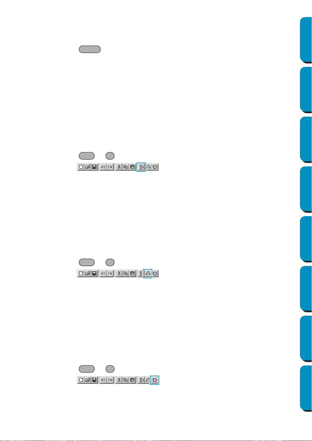
246
Contents Before Using Getting Started Design Center Layout & Editing
Programmable
Stitch Creator
Quick Reference Alphabetic Index
■ Delete
Purpose: Removes the selected line(s) from the screen without saving them in the clip-
board.
Shortcut key:
Toolbar: No button for this function
Operation:
1 Select one or more lines.
2 Click Edit, then Delete.
The selected line(s) are removed from the screen. Since they are not saved in the clipboard, the
only way to make them reappear is to use
Edit - Undo.
See also: “Undo” on page 244 and “Cut” on page 245
■ Mirror – Horizontal
Purpose: Flips the selected line(s) up/down.
Shortcut key: +
Toolbar:
Operation:
1 Select one or more lines.
2 Click Edit, then Mirror, then Horizontal.
The selected line(s) are replaced by their horizontal mirror image (top and bottom inverted). Two
successive applications of this function restores the original image.
See also: “Mirror – Vertical” and “Rotate” below
■ Mirror – Vertical
Purpose: Flips the selected line(s) left/right.
Shortcut key: +
Toolbar:
Operation:
1 Select one or more lines.
2 Click Edit, then Mirror, then Vertical.
The selected line(s) are replaced by their vertical mirror image (left and right inverted). Two suc-
cessive applications of this function restores the original image.
See also: “Mirror – Horizontal” above and “Rotate” below
■ Rotate
Purpose: Allows you to manually rotate the selected line(s) by an arbitrary angle.
Shortcut key: +
Toolbar:
Delete
Ctrl H
Ctrl J
Ctrl Y
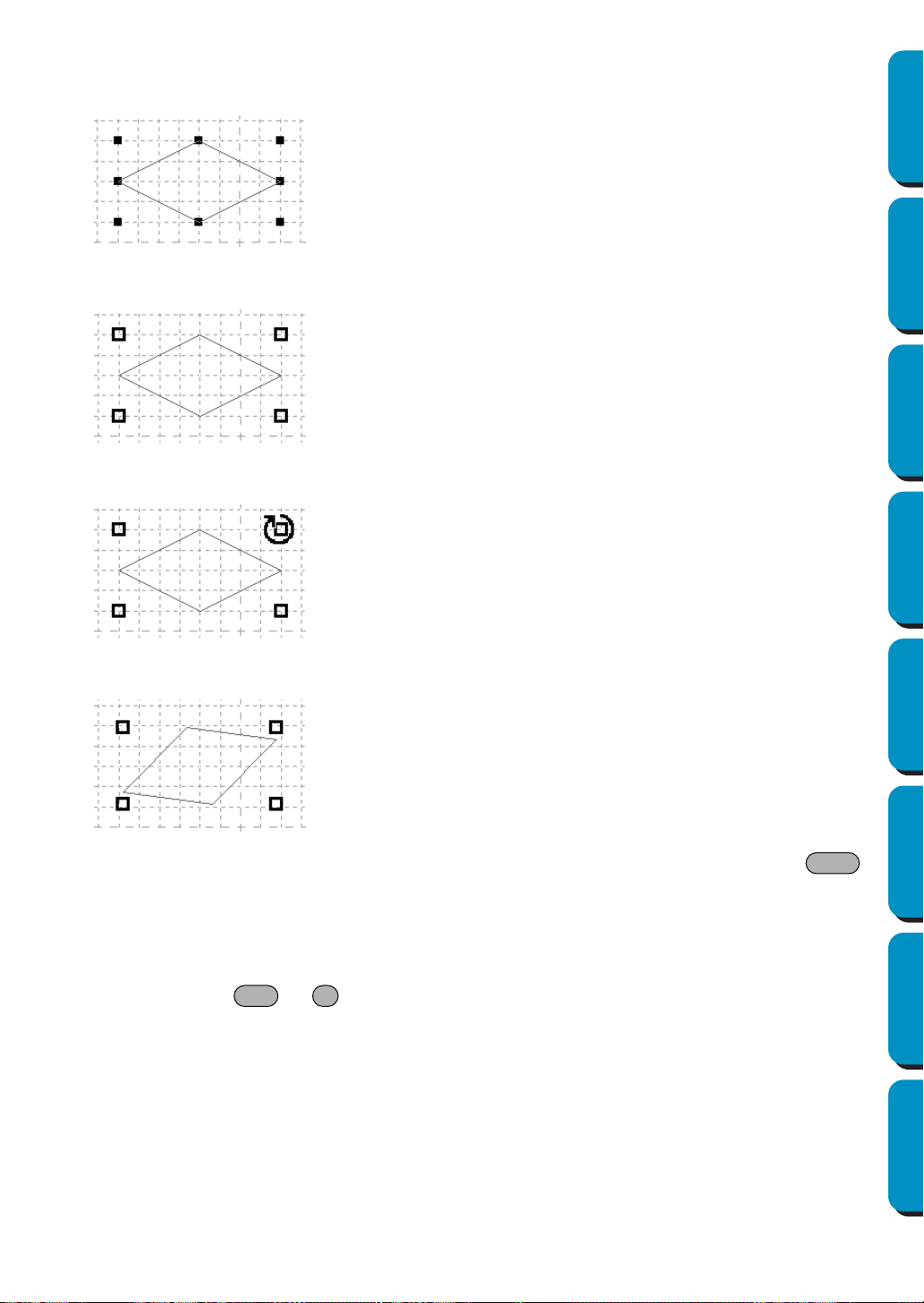
247
Contents Before Using Getting Started Design Center Layout & Editing
Programmable
Stitch Creator
Quick Reference Alphabetic Index
Operation:
1 Select one or more patterns.
2 Click Edit, then Rotate. The shape of the handles changes.
3 Move the cursor to one of the handles. The shape of the cursor changes.
4 Drag the handle to rotate the pattern the desired angle, and then release the mouse button.
A simple dragging of the mouse will rotate the line by 1 degree increments. Pressing the
key will rotate it by 15 degree increments.
■ Select All
Purpose: Selects all the patterns.
Shortcut key: +
Toolbar: No button for this function
Operation:
1 Make sure that the cursor must be in Selection mode.
2 Click Edit, then Select All.
Shift
Ctrl E
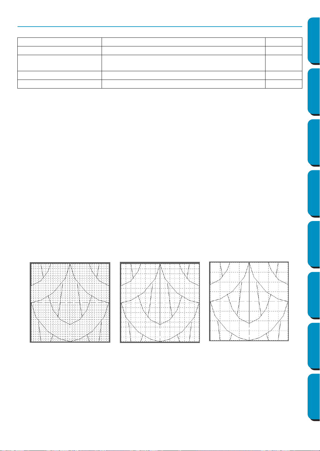
248
Contents Before Using Getting Started Design Center Layout & Editing
Programmable
Stitch Creator
Quick Reference Alphabetic Index
Display Menu
■ Grid
Purpose: Selects the work grid.
Shortcut key: No shortcut key for this function.
Toolbar: No button for this function
Operation:
1 Click Grid. The selected grid is preceded by a radio button.
2 Click the grid setting you need for the stitch pattern that you are creating or editing. You can also
switch grids while you are working on a stitch pattern, then continue drawing.
Click Wide: The grid step changes to 1/8 of a work area’s side.
Click Medium: The grid step changes to 1/16 of a work area’s side.
Click Narrow: The grid step changes to 1/32 of a work area’s side.
Click None: The grid disappears.
The grid setting will be saved when the application is turned off, so when the application is turned
on the next time, the same settings will be applied.
The horizontal and vertical lines that you draw on the work area always follow the grid. The points you
create by clicking the mouse are inserted at the intersection of the horizontal and vertical lines of the
grid, enabling you to draw diagonal lines as well. Regardless of where you click, a point will automatically
be inserted at the nearest intersection.
Select a different work grid according to the type of stitch you want to draw. Select a narrower grid for
drawing finer details or to give curve-like or circle-like looks to your stitch lines and select a wider grid if
you want to draw a simpler stitch pattern.
Grid Selects the work grid. page 248
Template-On, Faded, Off Turns on or off the template image or displays it faded. page 249
Preview
Turns the repeating image display of the pattern being cre-
ated on/off.
page 249
Toolbar Turns the Toolbar on/off. page 249
Status bar Turns the Status bar on/off. page 250
Example 2: Medium gridExample 1: Narrow grid Example 3: Wide grid
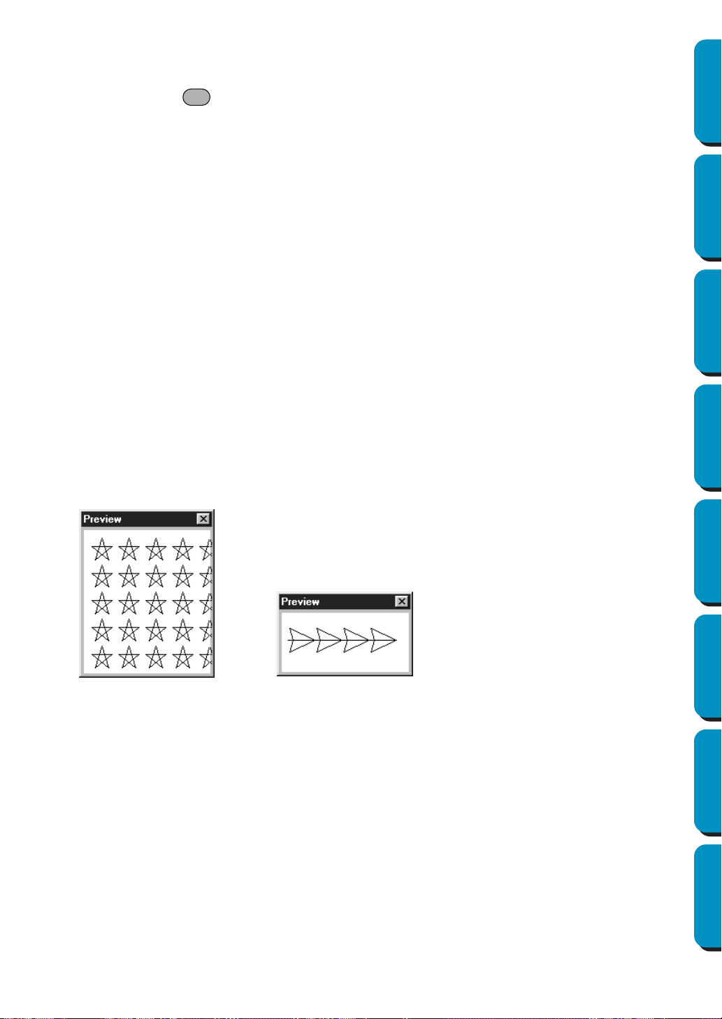
249
Contents Before Using Getting Started Design Center Layout & Editing
Programmable
Stitch Creator
Quick Reference Alphabetic Index
■ Template-On, Faded, Off
Purpose: Turns on or off the template image or displays it faded.
Shortcut key:
Toolbar: No button for this function
Operation:
1 Click Display, then Template, then select the desired setting.
◆ Click
On to display the original image.
◆ Click Faded to fade the image before displaying it.
◆ Click Off to hide the image.
This function is not available if a template image is not open.Press the shortcut key to switch
between displaying the template image to displaying it faded to hiding the image.
See also: “Template Open” on page 240
■ Preview
Purpose: Turns the repeating image display of the pattern being created on/off.
Shortcut key: No shortcut key for this function
Toolbar: No button for this function
Operation:
1 Click Display, then Preview.
If the Preview dialogue was not displayed, the Preview dialogue matching the mode setting will be
displayed, as shown in the examples below.
(Mode = Fill) (Mode = Motif)
When the application is turned off, the Preview dialog display’s On/Off condition and the display
position will be saved, so the next time the application is opened the same conditions will be shown.
■ Toolbar
Purpose: Turns the Toolbar on/off.
Shortcut key: No shortcut key for this function
Toolbar: No button for this function
Operation:
1 Click Display, then Toolbar.
The Toolbar will be toggled on/off.
See also: “Status bar” on page 250
F6
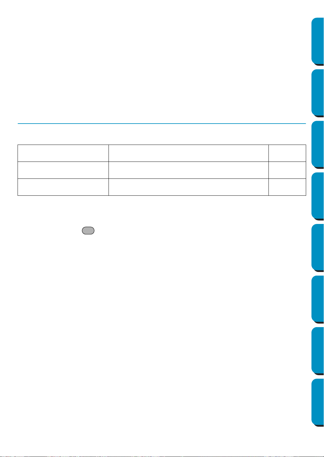
250
Contents Before Using Getting Started Design Center Layout & Editing
Programmable
Stitch Creator
Quick Reference Alphabetic Index
■ Status bar
Purpose: Turns the Status bar on/off.
Shortcut key: No shortcut key for this function
Toolbar: No button for this function
Operation:
1 Click Display, then Status Bar.
The Status Bar will be toggled on/off.
See also: “Toolbar” on page 249
Help Menu
The Help menu gives you access to the on-screen help information system.
■ Contents
Purpose: Starts the on-screen help information for this application.
Shortcut key:
Operation:
1 Click Help, then Contents.
A table of contents of the on-screen help information displays.
2 Refer to your Windows manual for the next operation.
See also: “About Programmable Stitch Creator” on page 251
■ Customer support
Purpose: Opens the FAQ (Frequently Asked Questions) page in this company’s Web site.
Shortcut key: No shortcut key for this function
Toolbar: No button for this function
Operation:
1 Click Help, then Customer support from the menu.
2 The browser installed in the computer will start, and open the FAQ page of this company’s Web
site.
NOTE:
This function cannot be used if there is no Internet browser correctly installed in the computer.
Contents
Starts the on-screen help information for this applica-
tion.
page 250
Customer support
Opens the FAQ (Frequently Asked Questions) page in
this company’s Web site.
page 250
About Programmable Stitch
Creator
Gives information about the version of this application. page 251
F1
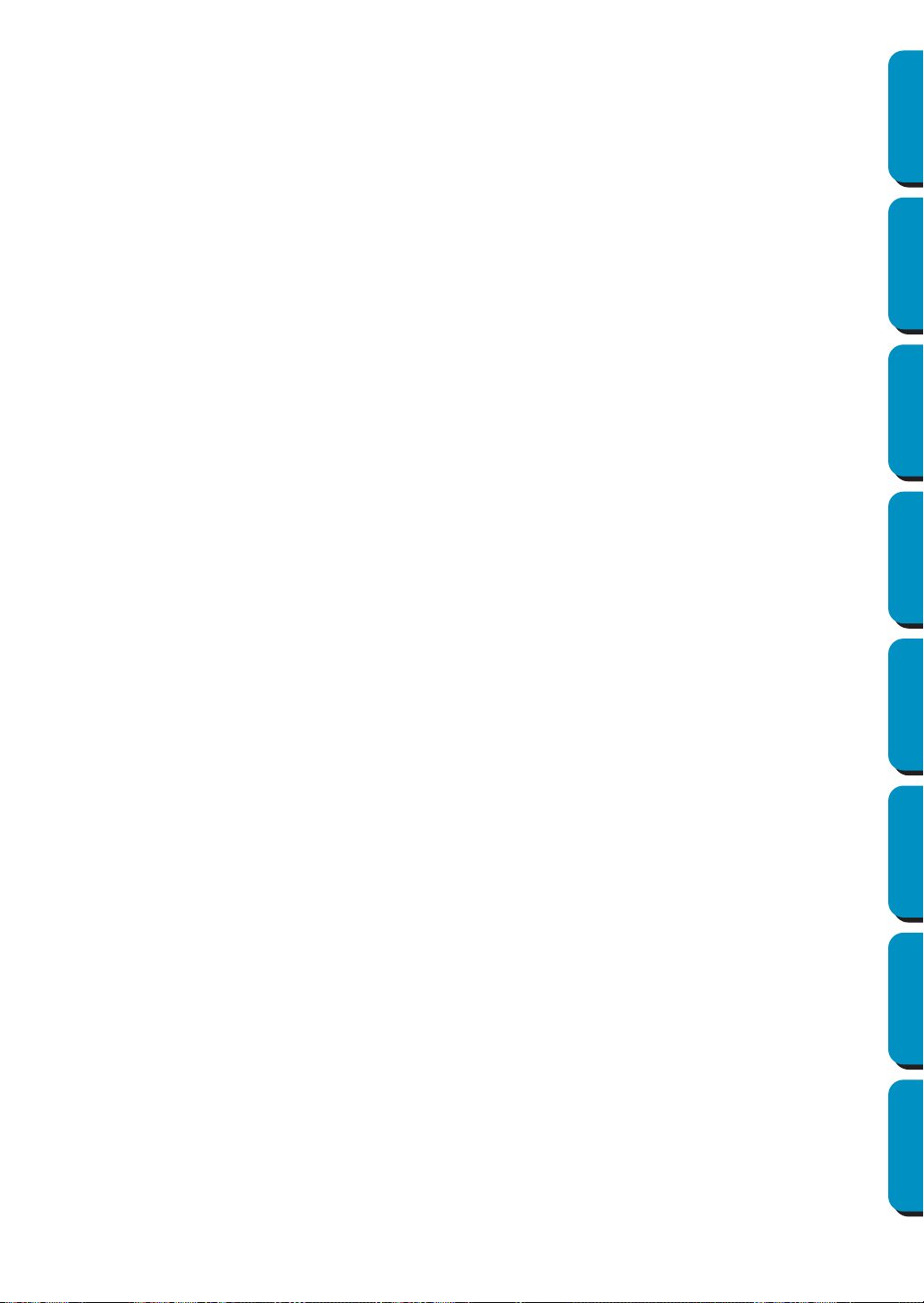
251
Contents Before Using Getting Started Design Center Layout & Editing
Programmable
Stitch Creator
Quick Reference Alphabetic Index
■ About Programmable Stitch Creator
Purpose: Gives information about the version of this application.
Shortcut key: No shortcut key for this function
Toolbar: No button for this function
Operation:
1 Click Help, then About Programmable Stitch Creator.
A dialog will display.
2 Click OK to remove it.
See also: “Contents” on page 250

252
Contents Before Using Getting Started Design Center Layout & Editing
Programmable
Stitch Creator
Quick Reference Alphabetic Index
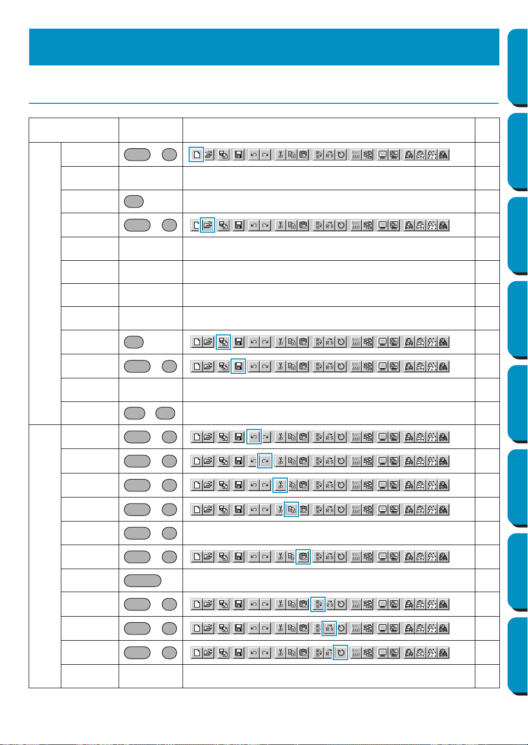
253
Contents Before Using Getting Started Design Center Layout & Editing
Programmable
Stitch Creator
Quick Reference Alphabetic Index
Design Center
Menu
Shortcut
key
Toolbar
Page
File
New Line
Image
+
82
New Figure
Data
–– 82
Wizard – 83
Open
+
85
Select TWAIN
device
–– 86
Input from
TWAIN device
–– 86
Input from
Clipboard
–– 87
Output to
Clipboard
–– 88
Import Figure 88
Save
+
89
Save As – – 89
Exit
+
–90
Edit
Undo
+
91
Redo
+
91
Cut
+
91
Copy
+
92
Duplicate
+
–92
Paste
+
92
Delete – 92
Mirror –
Horizontal
+
93
Mirror –
Vertical
+
93
Rotate
+
94
Numerical
Setting-Size
–– 94
Quick Reference
Ctrl N
F3
Ctrl O
F8
Ctrl S
Alt F4
Ctrl Z
Ctrl A
Ctrl X
Ctrl C
Ctrl D
Ctrl V
Delete
Ctrl H
Ctrl J
Ctrl Y
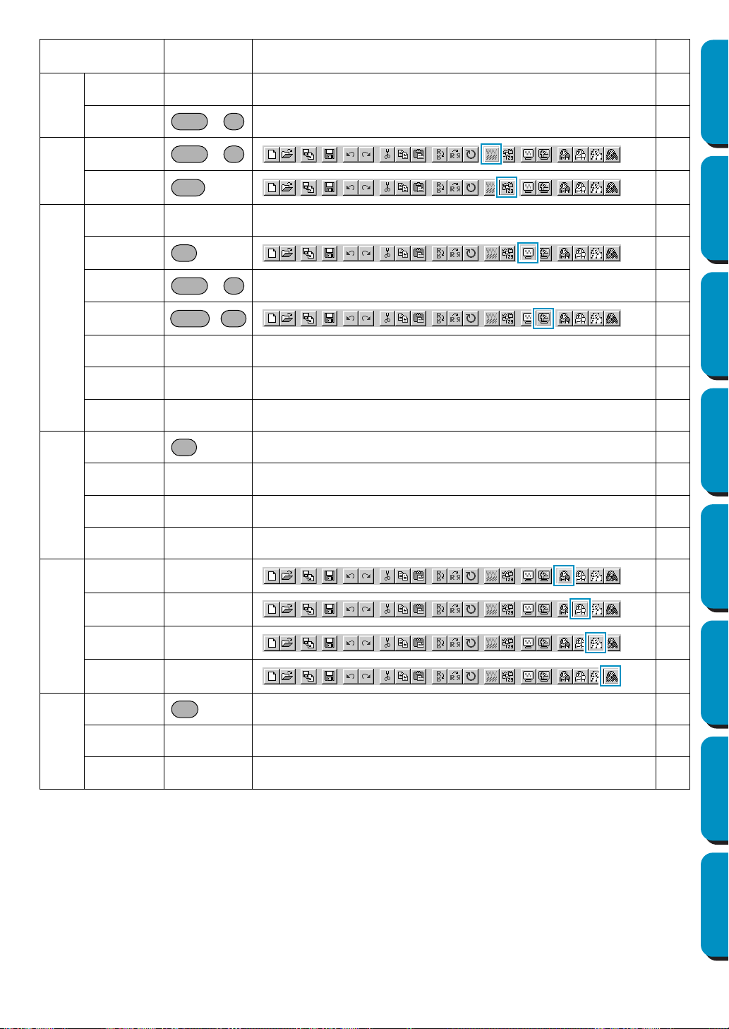
254
Contents Before Using Getting Started Design Center Layout & Editing
Programmable
Stitch Creator
Quick Reference Alphabetic Index
Edit
Numerical
Setting-Rotate
–– 95
Select All
+
–95
Sew
Sewing
Attributes
+
96
Sewing Order 100
Display
Grid Setup – – 103
Preview 104
Refresh
Window
+
–104
Realistic
Preview
+
104
Realistic Preview
Attribute Setting
– – 104
Toolbar – – 105
Status Bar – – 105
Option
Layout &
Editing
–106
Programmable
Stitch Creator
– – 106
Design Page
Property
– – 106
Select System
Unit
– – 107
Stage
To Original
Image
– 108
To Line Image – 108
To Figure
Handle
– 110
To Sew Setting – 112
Help
Contents – 113
Customer
support
– – 113
About Design
Center
– – 113
Menu
Shortcut
key
Toolbar
Page
Ctrl E
Ctrl W
F10
F9
Ctrl R
Shift F9
F5
F1
255
Contents Before Using Getting Started Design Center Layout & Editing
Programmable
Stitch Creator
Quick Reference Alphabetic Index
Layout & Editing
Menu
Shortcut
key
Toolbar
Page
File
New
+
149
Open
+
150
Import – from
File
151
Import – from
Design Center
153
Import – from
Card
– – 154
Save
+
156
Save As – – 156
Export – – 157
Write to Card –
Current
Design
157
Write to Card-
Other PES
files
+
–158
Property – – 161
Print Setup – – 161
Print Preview – – 163
Print
+
–164
Exit
+
–165
Ctrl N
Ctrl O
F8
F7
Ctrl S
F4
Shift F4
Ctrl P
Alt F4
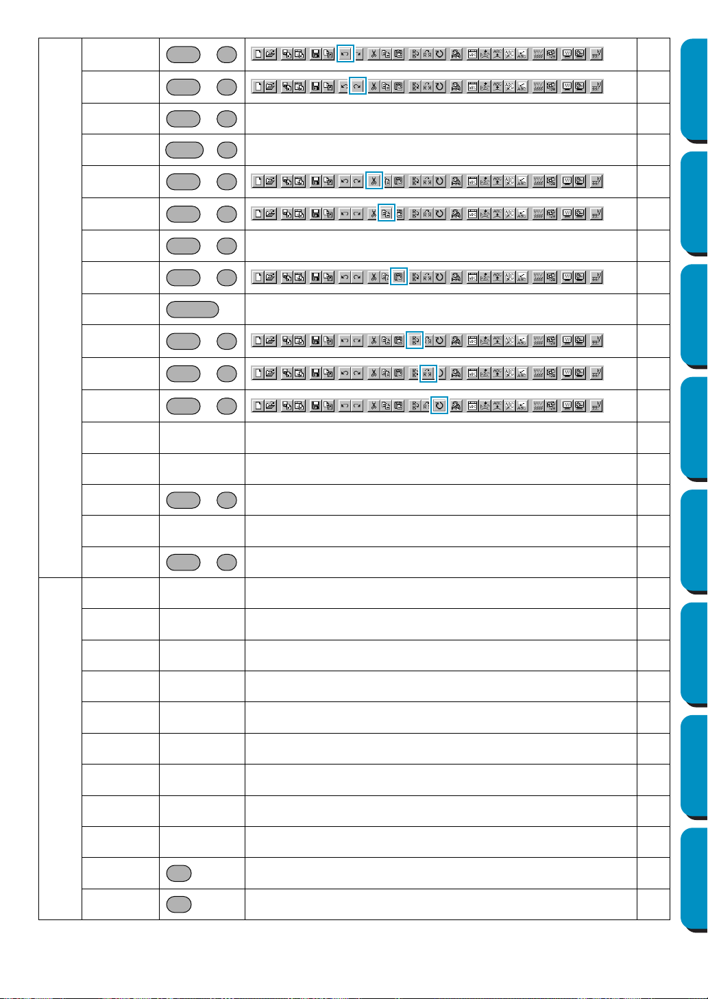
256
Contents Before Using Getting Started Design Center Layout & Editing
Programmable
Stitch Creator
Quick Reference Alphabetic Index
Edit
Undo
+
166
Redo
+
166
Group
+
–167
Ungroup
+
–167
Cut
+
167
Copy
+
168
Duplicate
+
–168
Paste
+
168
Delete – 168
Mirror –
Horizontal
+
169
Mirror –
Vertical
+
169
Rotate
+
170
Numerical
Setting-Size
– – 171
Numerical
Setting-Rotate
– – 172
Center
+
–172
Align – – 173
Select All
+
–174
Image
Input-from File – – 176
Input-from
TWAIN device
– – 176
Input-from
Portrait
– – 177
Input-from
Clipboard
– – 178
Output-to File – – 179
Output-to
Clipboard
– – 179
Select TWAIN
device
– – 179
Modify – – 180
Image to Stitch
Wizard
– – 181
Display Image-
On
–196
Display Image-
Faded
–196
Ctrl Z
Ctrl A
Ctrl G
Shift G
Ctrl X
Ctrl C
Ctrl D
Ctrl V
Delete
Ctrl H
Ctrl J
Ctrl Y
Ctrl M
Ctrl E
F6
F6
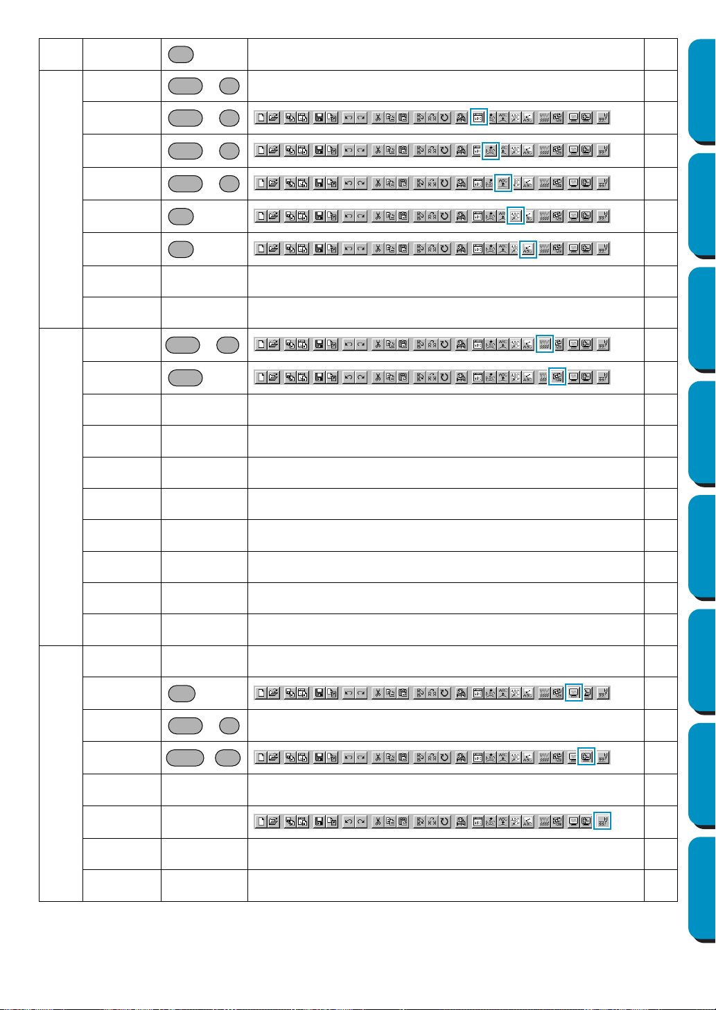
257
Contents Before Using Getting Started Design Center Layout & Editing
Programmable
Stitch Creator
Quick Reference Alphabetic Index
Image
Display Image-
Off
–196
Text
Edit Text
Letters
+
–197
Text Attribute
Setting
+
198
Fit Text to Path
Setting
+
199
Release Text
from Path
+
201
Transform Text 201
Clear
Transformation
202
TrueType Font
Attribute Setting
– – 202
Convert to
Outline Object
–
–
203
Sew
Sewing
Attribute Setting
+
204
Sewing Order 210
Set hole
sewing
– – 212
Cancel hole
sewing
– – 213
Stitch to Block – – 213
Convert to
Stitch
– – 214
Change colors
of a stitch object
– – 215
Select Sewing
Area
– – 216
Optimize hoop
change
– – 217
Optimize Entry/
Exit points
– – 218
Display
Grid Setup – – 219
Preview 220
Refresh
Window
+
–220
Realistic
Preview
+
220
Realistic Preview
Attribute Setting
– – 221
Stitch
Simulator
– 221
Toolbar – – 222
Status Bar – – 222
F6
Ctrl L
Ctrl K
Ctrl T
Ctrl Q
F2
F3
Ctrl W
F10
F9
Ctrl R
Shift F9
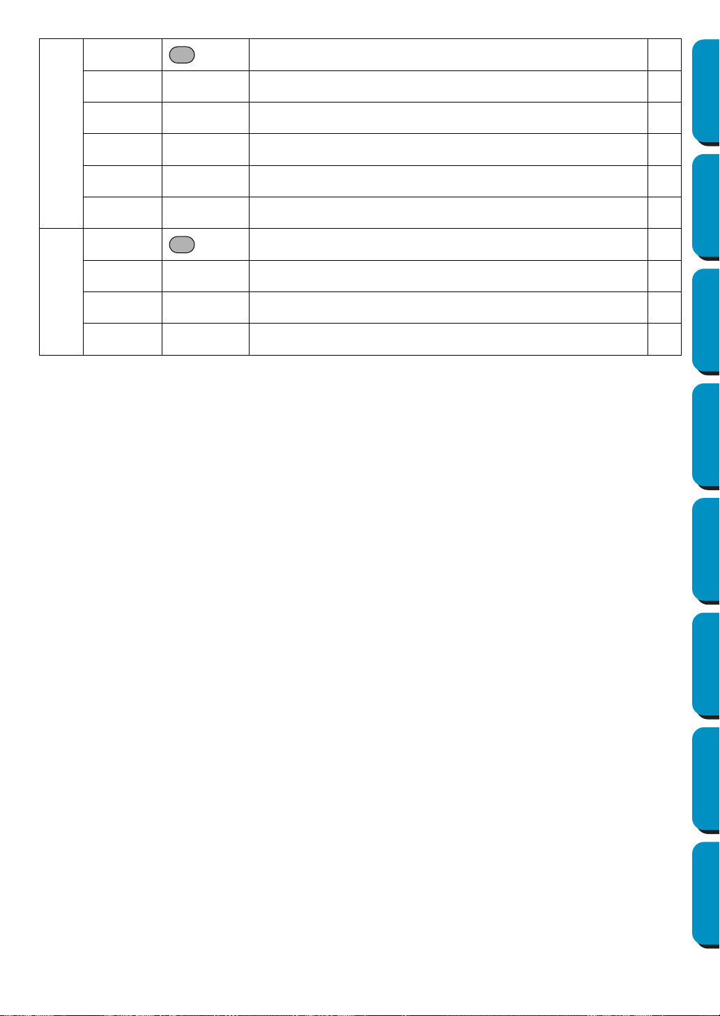
258
Contents Before Using Getting Started Design Center Layout & Editing
Programmable
Stitch Creator
Quick Reference Alphabetic Index
Option
Design Center – 223
Programmable
Stitch Creator
– – 223
Design
Property
– – 223
Design Page
Property
– – 225
Edit User
Thread Chart
– – 225
Select System
Unit
– – 229
Help
Contents – 230
Customer
support
– – 230
Online
Registration
– – 231
About Layout
& Editing
– – 231
F5
F1

259
Contents Before Using Getting Started Design Center Layout & Editing
Programmable
Stitch Creator
Quick Reference Alphabetic Index
Programmable Stitch Creator
Menu
Shortcut
key
Toolbar
Page
File
New
+
238
Open
+
238
Template Open – – 240
Save
+
240
Save As – – 241
Exit
+
– 241
Mode
Fill – – 242
Motif – – 243
Edit
Undo
+
244
Redo
+
244
Cut
+
245
Copy
+
245
Duplicate
+
– 245
Paste
+
245
Delete – 246
Mirror –
Horizontal
+
246
Mirror –
Vertical
+
246
Rotate
+
246
Select All
+
– 247
Display
Grid – – 248
Template-On,
Faded, Off
– 249
Preview – – 249
Toolbar – – 249
Status bar – – 250
Ctrl N
Ctrl O
Ctrl S
Alt
F4
Ctrl Z
Ctrl A
Ctrl X
Ctrl C
Ctrl D
Ctrl V
Delete
Ctrl H
Ctrl J
Ctrl Y
Ctrl E
F6
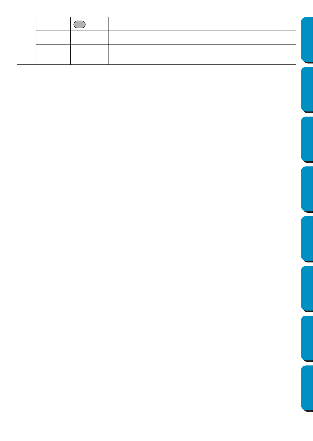
261
Contents Before Using Getting Started Design Center Layout & Editing
Programmable
Stitch Creator
Quick Reference Alphabetic Index
A
About Design Center 113
About Layout & Editing
231
About Programmable Stitch Creator
251
Align
173
Alignment
199
Angle
98, 207
Applique position
145
Arbitrary Shape Mask
184
Arc shape button
137
Auto Select
186, 191
Automatic punching
182
C
Cancel Hole Sewing 213
Card
49
CD-ROM
2
Center
172
Change Color
190, 192, 194
Change colors of a stitch object
215
Changing sewing order
211
Character Spacing
198
Circle and Arc Drawing mode
128
Clear Transformation
202
Color button
79, 144
Color Count
186
Color Reduction function
109
Color Set
191
Color tab
100
Contents
113, 230, 250
Conversion Priority
185, 189
Convert to Outline Object
203
Convert to Stitch
124, 214
Copies the Stage1 image data to the clipboard.
88
Copy
92, 168, 245
Creating a manual punching pattern
133
Creating a New Thread Chart
226
Creating a portrait
177
Creating data for the multi-position frame
55
Creating stitch data from image data
181
Creating outline data
203
Cross size
195
Cross stitch only
99, 209
Cross-stitching
195
Customer support
113, 230, 250
Cut
91, 167, 245
D
Delete 92, 168, 246
Deleting a Chart
226
Deleting points
68, 122, 236
Deleting stitch points
124
Density
97, 205, 207
Design Center
10, 11, 16, 61, 223
Design Center window
17
Design Page Color
185
Design Page Property
106, 225
Design Property
223
Detail
185, 189
Direction
98, 99, 199, 207, 208, 209
Display
2
Display Image – On, Faded, Off
196
Display Menu
248
Display menu
103, 219
Drawing a box
131
Drawing a broken line
69, 132, 237
Drawing a circle or an ellipse
129
Drawing a fan shape
130
Drawing an arc
129
Drawing an arc & string
130
Duplicate
92, 168, 245
E
Edge radius button 137
Edit List
186
Edit Menu
91, 166, 244
Edit text letters
197
Edit User Thread Chart
225
Editing a Chart
227
Editing entry/exit points of a shape object
124
Editing stitch data of a stitch object
123
Embroidery attributes
137
Emphasizing the Outline
184
Enlarging selected objects to the screen size
126
Enlarging Selected Outlines to the Screen Size
70
Entering text
127
Eraser
63
Exit
90, 165, 241
Export
157
Exporting
179
F
FAQ 113, 230, 250
Feathered Edge
209
Feathered Side
209
Figure handle image
10, 22, 61
File menu
81, 149, 238
File Property
161
Fill Mode
242
Fill stitch only
98, 208
Fit Design Page to window
64, 70, 76, 126
Fit Text to Path Setting
40, 199
Font
38
Font button
138
Frequency
98, 208
Alphabetic Index

262
Contents Before Using Getting Started Design Center Layout & Editing
Programmable
Stitch Creator
Quick Reference Alphabetic Index
G
Geometric attributes 136, 137
Grid
248
Grid Setup
103, 219
Group
167
H
Hard disk free space 2
H-Arrange (Horizontal Arrange)
99, 206, 209
Help menu
113, 230, 250
Hole Sewing
47
Hole sewing mode
76
Horizontal Alignment
200
I
Image to Stitch Wizard 181
Image Tune
183
Image Type
185, 189
Import – from Card
154
Import – from Design Center
31, 153
Import – from File
151
Import Figure
88
Importing Embroidery Patterns from Design Center
31
Input – from Clipboard
178, 179
Input – from File
176
Input – from Portrait
177
Input – from TWAIN device
176
Input From Clipboard
87, 178
Input from TWAIN device
86
Inserting points
68, 121, 236
Inserting stitch points
124
Installation
2
K
Kerning 198
L
Layout & Editing 9, 29, 106, 115
Line (all) setting mode
73
Line (part) setting mode
74
Line color
24
Line Drawing mode
69, 237
Line image
10, 61
Line Interval
191, 194
Line sew button
78, 142
Line sewing attribute
97
Line sewing attributes
205
Line Spacing
198
M
Manual Color Selection 186
Manual Punching mode
133
Mask
184
Max length
209
Max. Density
191, 194
Max. Number of Colors
195
Maximize button
17
Measure mode
135
Measuring the distance between two points
135
Memory
2
Menu Bar
238
Menu bar
81, 115, 148
Minimize button
17
Mirror – Horizontal
67, 93, 118, 169, 246
Mirror – Vertical
67, 93, 118, 169, 246
Mode Menu
242
Modify
180
Motif Mode
243
Motif Stitch only
206, 208
Motif stitch only
99
Moving lines
234
Moving patterns
66, 117
Moving points
68, 120, 235
Moving stitch points
124
Moving the Embroidery Pattern
35
multi-position embroidery frame
224
multi-position frame
55
N
New 149, 238
New Figure Data
82
New Line Image
82
Noise Reduction
109
Numerical Setting
94, 95, 171, 172
O
Offset-Direction 98, 208
Offset-Value
98, 208
Online Registration
231
Open
85, 150, 238
Operating system
2
Optimize Entry/Exit points
218
Optimize hoop change
56, 217
Option menu
106, 223
Original bitmap image
61
Original card
157, 158
Original image
10
Outline Drawing mode
131
Output – to Clipboard
179
Output – to File
179
Output To Clipboard
88
Oval
36
P
Page display 76
Part tab
102
Paste
92, 168, 245
Path shape button
138
Pattern
98, 99, 206, 208, 209
Pattern Direction
98
Pattern Size-Height
98, 99, 206, 208
Pattern Size-Width
98, 99, 206, 208
PC
2
Pen
63
Photo embroidering
183, 190
Photo/Cartoon
185, 189
Point Edit mode
68, 120, 235

263
Contents Before Using Getting Started Design Center Layout & Editing
Programmable
Stitch Creator
Quick Reference Alphabetic Index
Preview 28, 48, 104, 220, 249
Print
164
Print Preview
163
Print Setup
161
Printer
2
Processor
2
Programmable Fill Stitch
43
Programmable Stitch
53
Programmable Stitch Creator
10, 50, 51, 106, 223,
233
Programmed fill stitch
98
Programmed fill stitch only
208
Property
161
Pull Compensation
98, 207
Q
Quick Reference 253
R
Realining 122
Realistic Preview
104, 220
Realistic Preview Attribute Setting
104, 221
Rectangle Drawing mode
131
Redo
91, 166, 244
Refresh Window
104, 220
Region color
26
Region setting mode
71
Region sew
77
Region sew button
143
Region sew type
26
Region sewing attribute
97, 206
Release Text from Path
201
Reorienting a tangent to a point
121
Resolution
111
Return to the standard scale
126
Rotate
67, 94, 119, 170, 246
Rotate angle
198
Row Offset
99, 209
Run Pitch
99, 209
Run pitch
97, 185, 189, 206
Run times
97, 206
S
Save 28, 49, 58, 89, 156, 240
Save As
89, 156, 241
Scaling lines
235
Scaling patterns
66, 118
Select All
95, 174, 247
Select Design Page Size
225
Select Sewing Area
216
Select System Unit
107, 229
Select TWAIN device
86, 179
Selecting characters on a text pattern
123
Selecting lines
234
Selecting patterns
66, 117
Selecting patterns 2
117
Selecting stitch points
124
Selection Mode
234
Selection mode
66, 117
Serial port
2
Set Hole Sewing
47, 212
Setting the Thread Color and Stitch
77
Sew menu
96, 204
Sew Page Color
185
Sew Setting
10, 23, 61
Sewing Attribute Setting
204
Sewing Attributes
23, 96
Sewing Attributes bar
77, 136
Sewing direction
98, 207
Sewing Option
185, 189, 191, 194
Sewing Order
46, 100, 210
Size
99, 209
Special colors
145
Stage
10, 61
Stage Menu
108
Status bar
105, 222, 250
Step Pitch
98, 208
Stitch
77, 80, 142
Stitch selector
80, 146
Stitch Simulator
221
Stitch times
195
Stitch to block
213
System requirements
2
T
Template Open 240
Template-On, Faded, Off
249
Text
38
Text Attribute Setting
198
Text attributes
136, 138
Text Input mode
127
Text menu
197
Text Orientation
200
Text size button
140
The other side
200
Thinning Process
111
Thread Chart
79, 144, 186, 191, 195
Thread color
142
Times
99, 209
To Figure Handle
110
To Line Image
108
To Original Image
108
To Sew Setting
112
Tone
109
Tool Box
63, 65, 71, 116, 234
Toolbar
81, 105, 148, 222, 249
Transform level button
141
Transform Text
201
TrueType Font
128, 140, 202
TWAIN
87, 177
Type
98, 207
U
Under Sewing 97, 207
Undo
91, 166, 244
Ungroup
167
USB card writer module
1
Use Color
189, 194

264
Contents Before Using Getting Started Design Center Layout & Editing
Programmable
Stitch Creator
Quick Reference Alphabetic Index
Use Color List 186, 191
Use Color List Summary
186, 192
Use Pattern
99, 208
Using the Menu Bar
238
V
V-Arrange (Vertical Arrange) 99, 206, 209
Vertical Alignment
200
Vertical Offset
198
W
Wizard 83
Write the data to an original card
58
Write to Card – Current Design
157
Write to Card – Other PES files
158
Z
Zigzag width 97, 205
Zoom mode
125
Zoom-in mode
64, 69, 76
Zooming in
125
Zooming In and Out
32
Zooming out
126
Zooming to the real size
126
Zoom-out mode
64, 70, 76

Read the following before opening the CD-ROM package
Thank you for purchasing this software. Before opening the CD-ROM package for this software,
carefully read the following Product Agreement, which has been provided for this product. Use this
software only if you agree to the terms of this agreement. By opening the CD-ROM package, you agree
to the conditions of its use. This product cannot be returned after it has been opened.
General Terms
This is an agreement between you (the end-user) and our company for this product.
Use of this product
You may install and use this product on only one computer.
Limitations on Duplications
You may not duplicate this product, except for backup purposes.
Limitations on Modifications
You may not modify or disassemble this product in any way.
Limitations on Transfer
This software may not be transferred to or used in any other way by a third party.
Warranty
We accept no responsibility for your choice or use of this product or for any damages that
may arise out of its use.
Others
This product is protected by copyright laws.
Product Agreement
1.
2.
3.
4.
5.
6.
7.
Portions of this product were created using technology from Softfoundry International Pte. Ltd.

ENGLISH
XC3894-001
Printed in Japan