1
Lowes.com/harborbreeze
Questions, problems, missing parts? Before returning to your retailer, call our customer
service department at 1-800-643-0067, 8 a.m. - 6 p.m., EST, Monday - Thursday, 8 a.m. - 5 p.m.,
EST, Friday.
ATTACH YOUR RECEIPT HERE
Serial Number _________________________ Purchase Date _________________________
Harbor Breeze® is a registered trademark
of LF, LLC. All Rights Reserved.
AB15785
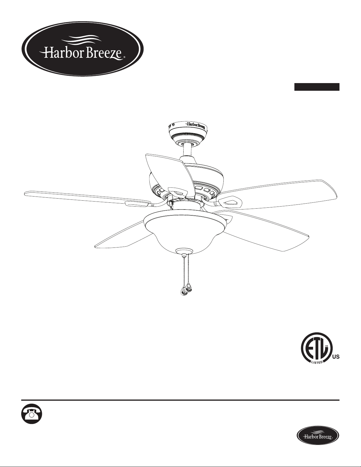
ITEM #0747607, 0747608
SAGECOVE CEILING FAN
MODEL #40840, 40841
Español p. 22

2
Lowes.com/harborbreeze
TABLE OF CONTENTS
Package Contents .................................................................3
Hardware Contents ................................................................4
Safety Information .................................................................5
Preparation ......................................................................6
Initial Installation ..................................................................7
Standard or Angle Mounting Instructions. . . . . . . . . . . . . . . . . . . . . . . . . . . . . . . . . . . . . . . . . . . . . . . . 9
Closemount Instructions ...........................................................11
Wiring .........................................................................12
Final Installation. . . . . . . . . . . . . . . . . . . . . . . . . . . . . . . . . . . . . . . . . . . . . . . . . . . . . . . . . . . . . . . . . . 13
Operating Instructions .............................................................17
Care and Maintenance ............................................................18
Troubleshooting ..................................................................18
Limited Lifetime Warranty ..........................................................20
Replacement Parts List ............................................................21
3
Lowes.com/harborbreeze
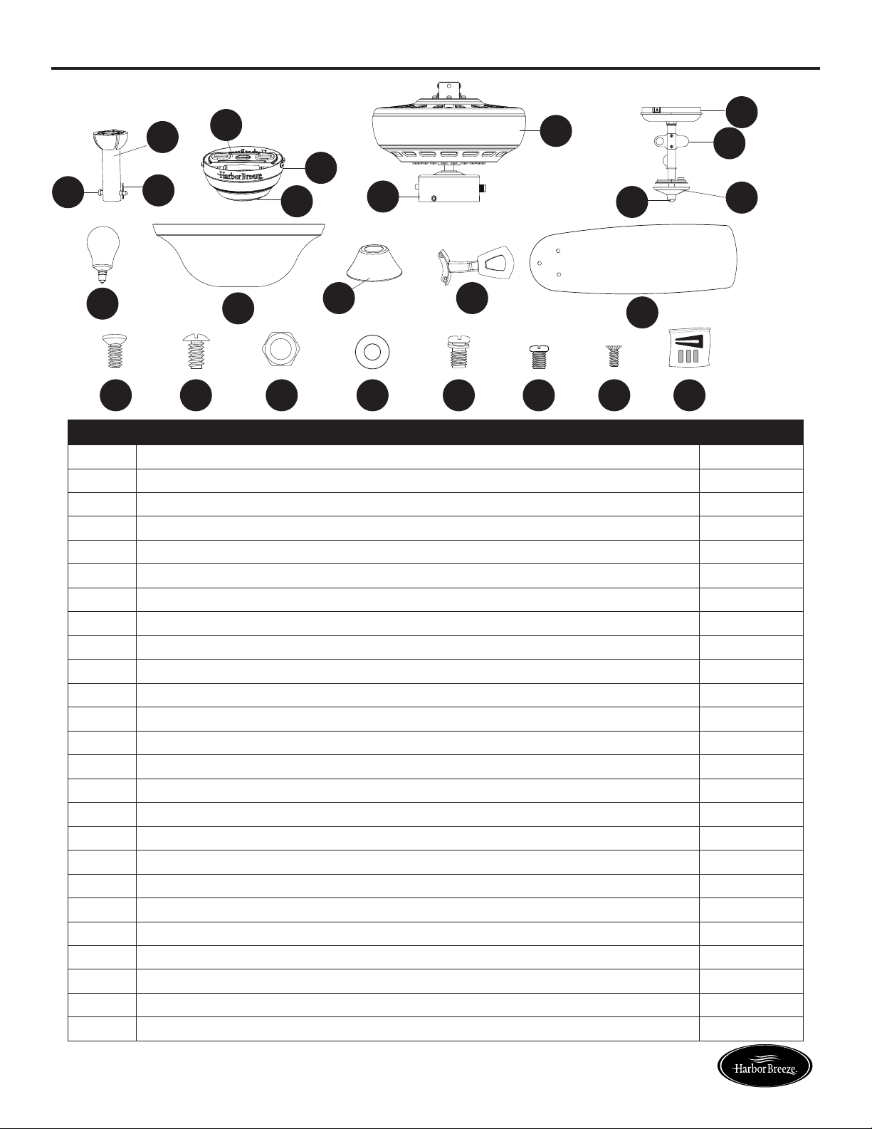
PACKAGE CONTENTS
PART DESCRIPTION QUANTITY
A Downrod 1
B Downrod Pin (preassembled to Downrod [A]) 1
C Downrod Clip (preassembled to Downrod [A]) 1
D Mounting Bracket (preassembled to Canopy [E]) 1
E Canopy 1
F Canopy Cover (preassembled to Canopy [E]) 1
G Motor Assembly 1
H Switch Housing (preassembled to Motor Assembly [G]) 1
I Switch Housing Cap (preassembled to Light Kit [J]) 1
J Light Kit 1
K Finial Cap (preassembled to Light Kit [J]) 1
L Finial (preassembled to Light Kit [J]) 1
M Bulb 2
N Glass Bowl 1
O Yoke Cover 1
P Blade Arm 5
Q Blade 5
R Motor Screw (preassembled to Motor Assembly [G]) 10 + 1 extra
S Mounting Bracket Screw (preassembled to Mounting Bracket [D]) 4
T Hex Nut (preassembled to Light Kit [J]) 1
U Rubber Washer (preassembled to Light Kit [J]) 1
V Phillips-head Closemount Screw (preassembled to Motor Assembly [G]) 3
W Set Screw (preassembled to Motor Assembly [G]) 2
X Switch Housing Screw (preassembled to Switch Housing Cap [I]) 3
Y Blade Balancing Kit 1
A
C
B
D
E
F
G
H
I
J
K
L
M
N
O P
Q
R S T U V W X Y
4
Lowes.com/harborbreeze
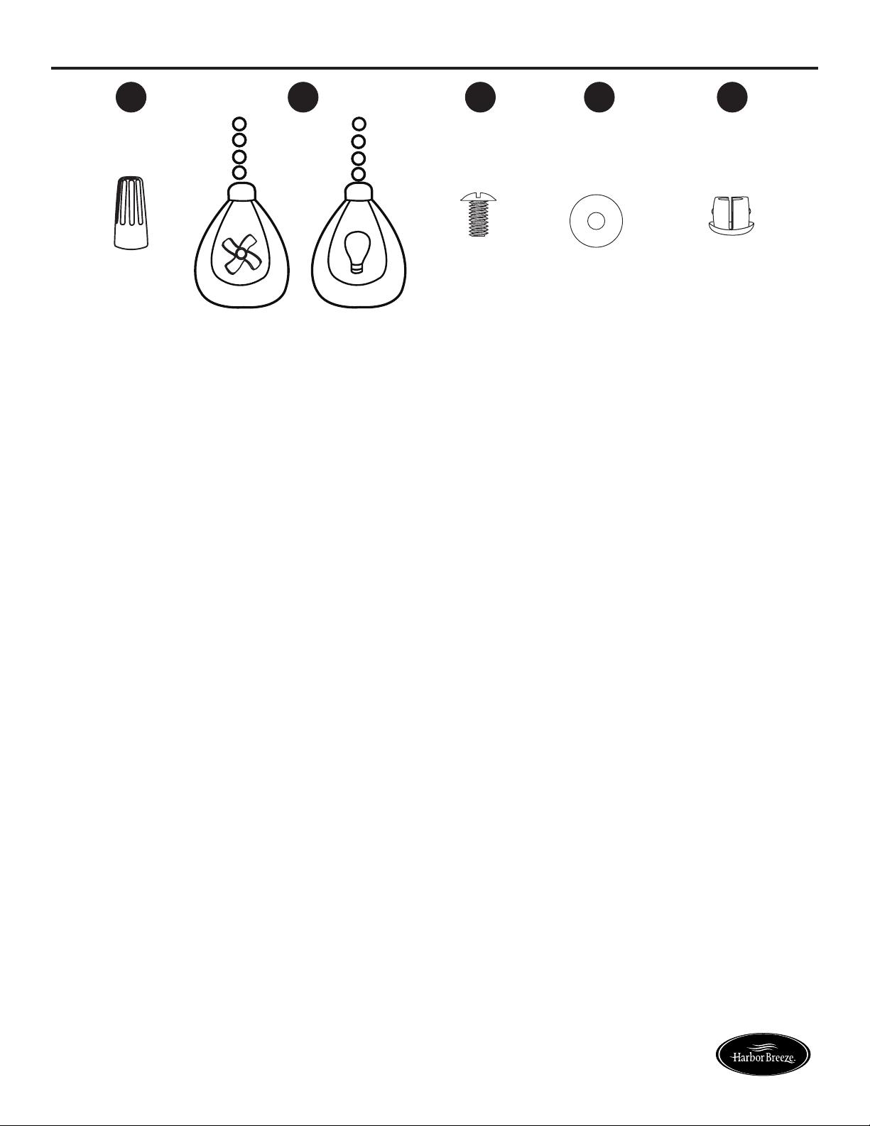
HARDWARE CONTENTS (shown actual size)
Wire Connector
Qty. 3
+ 1 extra
Pull Chain Extension
Qty. 2
Blade Screw
Qty. 15
+ 1 extra
Blade Washer
Qty. 15
+ 1 extra
Plug Button
Qty. 1
AA
BB CC DD
EE
H
a
r
b
o
r
B
r
e
e
z
e
H
a
r
b
o
r
B
r
e
e
z
e
5
Lowes.com/harborbreeze
SAFETY INFORMATION
Please read and understand this entire manual before attempting to assemble, operate or install the
product.
• Before you begin installing the fan, disconnect the power by removing fuses or turning off the circuit
breakers.
• Make sure all electrical connections comply with local codes, ordinances, the National Electrical
CodeandANSI/NFPA70-199.Hireaqualiedelectricianorconsultado-it-yourselfwiring
handbook if you are unfamiliar with installing electrical wiring.
• Make sure the installation site you choose allows a minimum clearance of 7 ft. from the blades to
theoorandatleast30in.fromtheendofthebladestoanyobstruction.
• The net weight of this fan is:14.75 lbs.
DANGER: When using an existing outlet box, make sure the outlet box is securely attached to
the building structure and can support the full weight of the fan. Failure to do this can result in serious
injury or death. The stability of the outlet box is essential in minimizing wobble and noise in the fan
after installation is complete.
WARNING: To avoid personal injury, the use of gloves may be necessary while handling fan
parts with sharp edges.
WARNING: Using a full-range dimmer switch to control fan speed will cause a loud humming
noisefromthefan.Toreducetheriskofreorelectricshock,doNOTuseafull-rangedimmerswitch
to control the fan speed.
WARNING: Toreducetheriskofre,electricshockorpersonalinjury,mountthefantoanoutlet
box marked “ACCEPTABLE FOR FAN SUPPORT” and use the mounting screws provided with the
outletbox.Mostoutletboxescommonlyusedforthesupportoflightingxturesarenotacceptable
forfansupportandmayneedtobereplaced.Consultaqualiedelectricianifindoubt.Securethe
outlet box directly to the building structure. The outlet box and its support must be able to support the
moving weight of the fan (at least 35 lbs.).
WARNING: Toreducetheriskofre,electricshockorpersonalinjury,wireconnectorsprovided
with this fan are designed to accept only one 12-gauge house wire and two lead wires from the fan. If
your house wire is larger than 12-gauge and/or there is more than one house wire to connect to the
two fan lead wires, consult an electrician for the proper size wire connectors to use.
WARNING: Toreducetheriskofre,electricshockorpersonalinjury,donotbendtheblade
arms when installing them, balancing the blades or cleaning the fan. Do not insert objects between
the rotating fan blades.
WARNING: To reduce the risk of personal injury, use only parts provided with this fan. The use
of parts OTHER than those provided with this fan will void the warranty.
6
Lowes.com/harborbreeze
SAFETY INFORMATION
CAUTION: Read all instructions and safety information before installing your new fan. Review the
accompanying assembly diagrams.
CAUTION: Be sure the outlet box is properly grounded or that a ground (green or bare) wire is present.
CAUTION: Carefully check all screws, bolts and nuts on the fan motor assembly to ensure they are
secured.
PREPARATION
Before beginning the assembly of this product, ensure that all parts are present. Compare all parts
with the package contents list and hardware contents list. If any part is missing or damaged, do not
attempt to assemble the product.
Estimated Assembly Time: 120 minutes
Tools Required for Assembly (not included): Electrical Tape, Phillips Screwdriver, Pliers, Safety
Glasses, Step Ladder, Wire Cutters and Wire Strippers
Helpful Tools (not included): AC Tester Light, Tape Measure and Wiring Handbook
7
Lowes.com/harborbreeze
INITIAL INSTALLATION
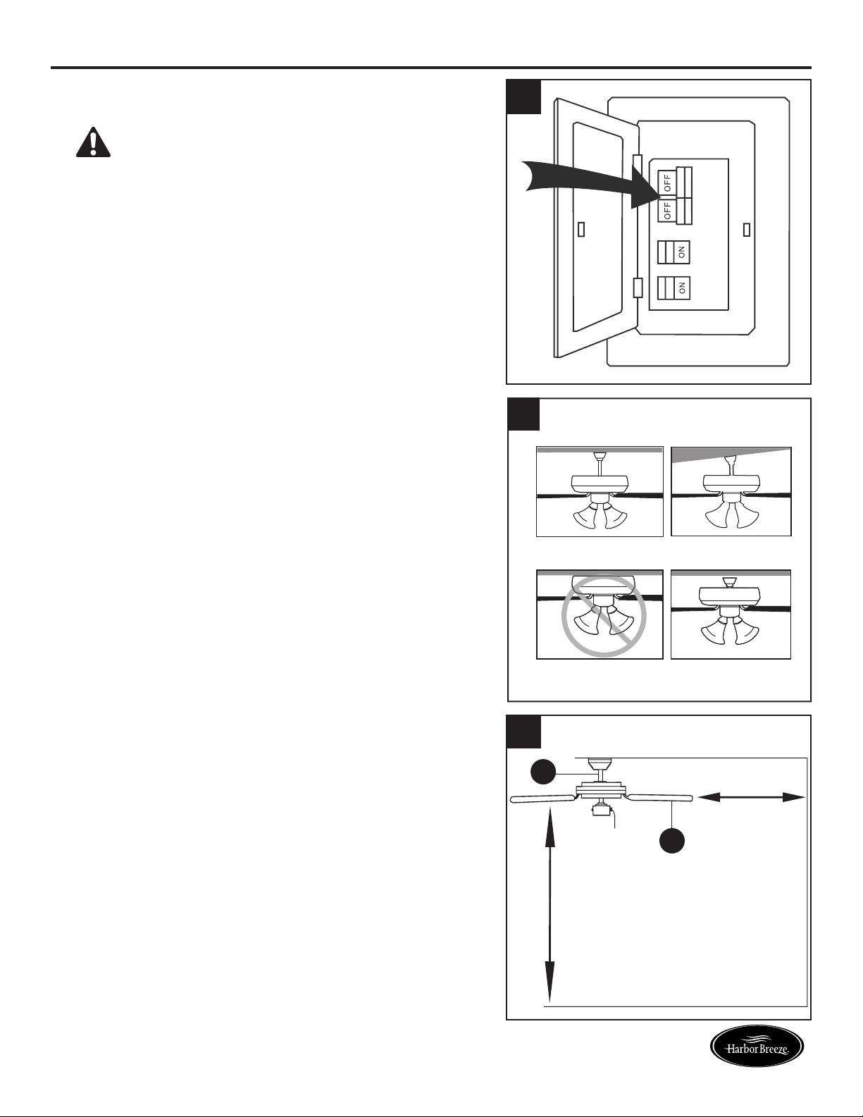
1. Turn off the circuit breakers and the wall switch to the
fan supply line leads.
DANGER: Failure to disconnect the power
supply prior to installation may result in serious injury
or death.
2. Determine the mounting method to use.
Standard mounting is best suited for ceilings 8 ft.
or higher. For taller ceilings you may want to use a
longer downrod (not included).
Angle-style mounting is best suited for angled or
vaulted ceilings. A longer downrod is sometimes
necessary to ensure proper blade clearance.
Note: If using the angle mount, check to ensure the
ceiling angle is not steeper than 16°.
Closemount-style mounting is more suitable for
ceilings lower than 8 ft. high.
Flushmount installation is not available for this item.
2
Standard Mounting
Flushmount Closemount
Angle Mounting
3. Ensure the blades (Q) will be at least 30 in. from
any obstructions. Also check the downrod (A) length
to ensure the blades (Q) will be at least 7 ft. above
theoor.
A
7 ft.
Minimum
30 in.
Minimum
3
1
A
Q
8
Lowes.com/harborbreeze
INITIAL INSTALLATION
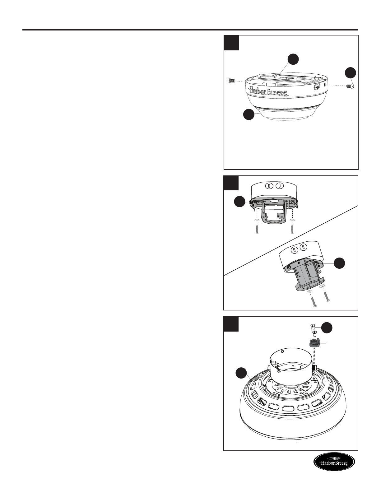
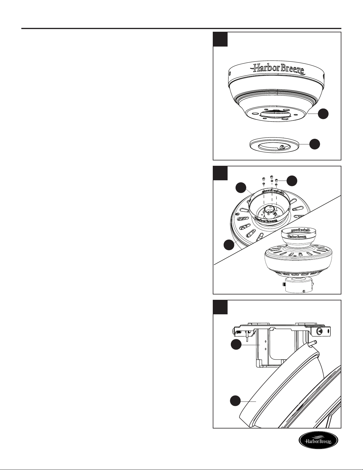
4. Loosen all four preassembled mounting bracket
screws (S), then completely remove the two
mounting bracket screws (S) from the round holes
of canopy (E). Set aside for later use.
Detach mounting bracket (D) from canopy (E).
5. Attach mounting bracket (D) to outlet box (not
included) using screws and washers provided with
the outlet box.
CAUTION: It is very important to use the proper
hardware when installing the mounting bracket (D) as
this will support the fan.
Important: If using the angle mount, ensure the open
end of the mounting bracket (D) is installed facing the
higher point of the ceiling.
6. Remove all 10 preassembled motor screws (R) and
vepreassembledplasticmotorblocksfromthe
underside of the motor assembly (G). Discard the
motor blocks, but keep the motor screws (R) for later.
For Standard or Angle Mounting Instructions, continue
to page 9. For Closemount Instructions, proceed to
page 11.
G
5
6
4
E
D
S
D
D
R
Standard or
Closemount
Mounting
Angle
Mounting
Motor
Block
9
Lowes.com/harborbreeze
STANDARD OR ANGLE MOUNTING INSTRUCTIONS
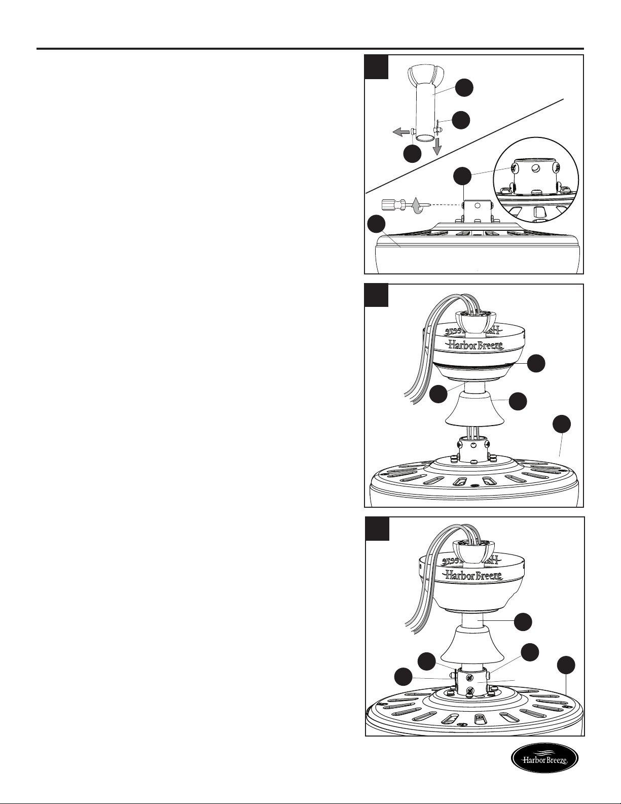
1. Remove the downrod pin (B) and downrod clip (C) from
the downrod (A). Then partially loosen the set screws
(W) in the yoke at the top of the motor assembly (G).
2. Insert the downrod (A) through the canopy (E) and yoke
cover (O). Feed the wires from the motor assembly (G)
through the downrod (A).
3. Slide the downrod (A) into the yoke of the motor
assembly (G), align the holes, then re-install the
downrod clip (C) and downrod pin (B). Secure with set
screws (W).
A
G
B
C
W
2
E
A
O
G
3
A
C
W
B
G
Yoke
1
Yoke
10
Lowes.com/harborbreeze
STANDARD OR ANGLE MOUNTING INSTRUCTIONS
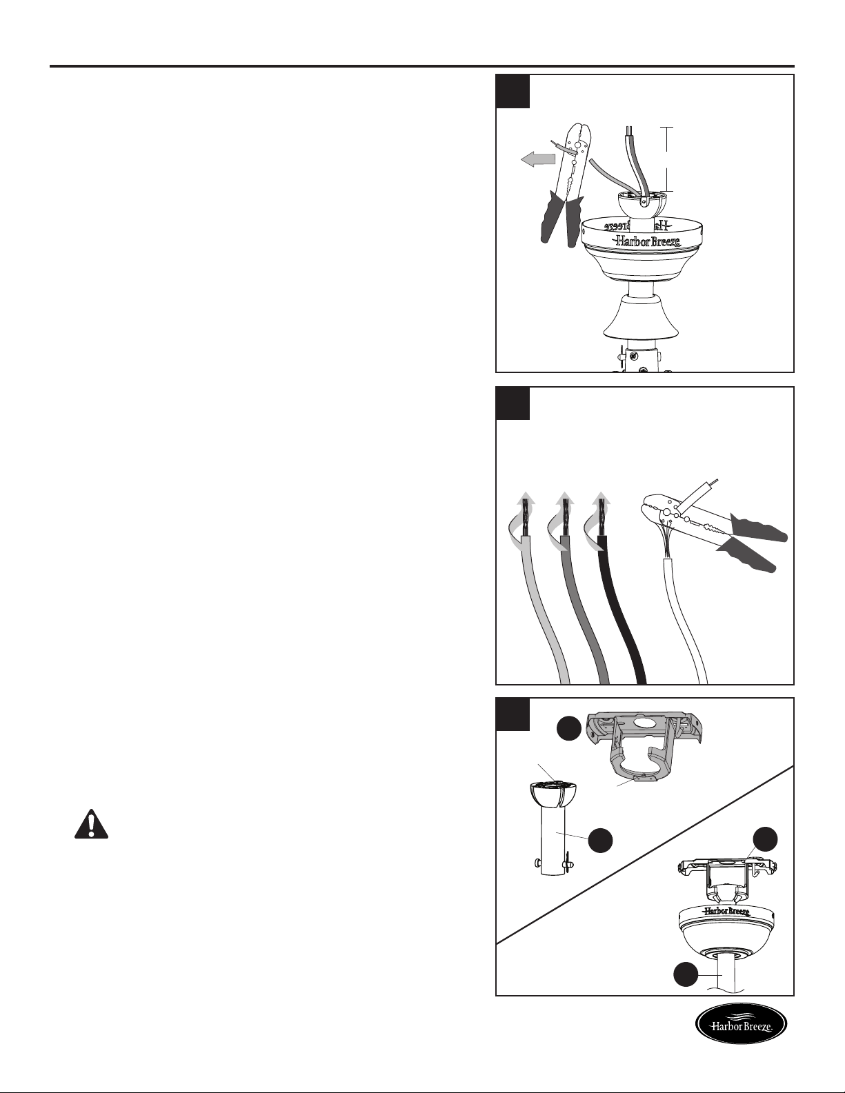
4. Depending on the length of downrod you use, you
may need to cut the lead wires back to simplify the
wiring. If you decide to cut back the lead wires, it is
suggested you do so in the following manner: Take
the lead wires and make sure you have pulled them
all the way through the top of the downrod. Measure
8 inches of lead wire, then cut the excess wire off with
wire cutters (not included).
5. If you decided to cut back the lead wire in Step 4, strip
1/2 in. of insulation from the end of the white wire.
Twist the stripped ends of each strand of wire within
the insulation with pliers (not included). Repeat this
step for black, blue and green wires.
Note: If you did not cut back the lead wires in Step 4,
Step 5 is not necessary and you may proceed to Step 6.
6. Install the ball end of the downrod (A) into the opening
of mounting bracket (D). Align one of the four slots in
the ball with the tab in the mounting bracket (D).
Note: The downrod (A) should not rotate if installed
correctly.
DANGER: Failure to align the slot in the
downrod (A) with the tab of the mounting bracket (D)
may cause the fan to wobble or fall, which could result
in serious injury or death.
Proceed to the Wiring on page 12.
4
5
6
A
A
D
D
Tab
Slot
8 in.
11
Lowes.com/harborbreeze
CLOSEMOUNT INSTRUCTIONS
Helpful Hint: The downrod (A), canopy cover (F) and
yoke cover (O) are not used in this type of installation.
1. Remove the canopy cover (F) from the bottom of the
canopy (E).
2. Remove three Phillips-head closemount screws (V)
from the top of the motor assembly (G). Align the
canopy (E) with the holes in the top of the motor
assembly (G), then re-install the Phillips-head
closemount screws (V) to secure the canopy (E) to
the top of the motor assembly (G).
3. Raise the fan and place the canopy (E) on the hook
on the mounting bracket (D), temporarily leaving
hands free for the wiring process.
1
F
E
2
V
E
E
D
G
3
12
Lowes.com/harborbreeze
WIRING
WARNING:Toreducetheriskofre,electricalshockorpersonalinjury,wireconnectors
provided with this fan are designed to accept only one 12-gauge house wire and two lead wires from
the fan. If your house wire is larger than 12-gauge and there is more than one house wire to connect
to the two fan lead wires, consult an electrician for the proper size wire connectors to use.
CAUTION: Be sure the outlet box is properly grounded or that a ground (green or bare) wire is present.
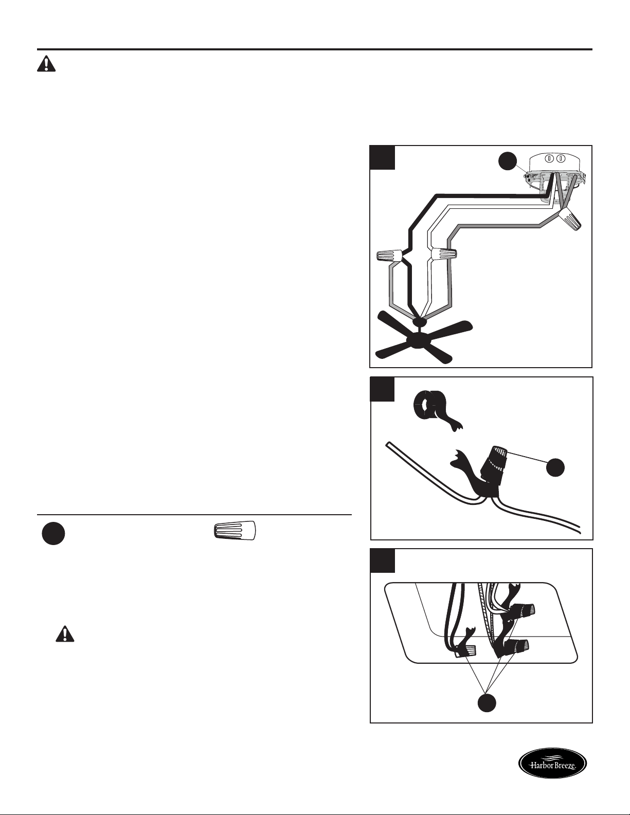
1. Connect household supply and fan wires according to
the diagram and these steps:
•ConnecttheGreenwirefromthedownrod(A)and
mounting bracket (D) to the Bare/Green supply wire.
Note: Closemount installation does not use
downrod (A), so there will only be two Green wires
to connect.
•ConnecttheWhitewirefromthefantotheWhite
supply wire.
•ConnecttheBlackandBluewiresfromthefantothe
Black supply wire.
•Secureallwiringconnectionstogetherwithwire
connectors (AA).
Note: If there is a second hot/power wire coming from
the outlet box, connect it to the Blue (light power) fan
wire for separate light and fan control.
Note: The Black wire is hot power for the fan. The
White wire is common for the fan and light kit. The
Blue wire is hot power for light. The Green wire is the
ground wire. If household supply wires are different
colors than referred to above, it is recommended a
professional electrician determines the proper wiring.
Hardware Used
AA
Wire Connector x 3
Black (Hot)
White (Neutral)
Bare/Green (Ground)
Black
Blue
White
Green
2. Wrap electrical tape (not included) around each
individual wire connector (AA) down to the wire.
3. Turn the spliced/taped wires upward and gently push
the wires and wire connectors (AA) into the outlet box.
WARNING: Ensure no bare wire or wire strands
are visible after making connections. Place the
Green and White wire connections on the opposite
side of the outlet box from the Black and Blue wire
connections.
1
3
AA
AA
D
2
13
Lowes.com/harborbreeze
FINAL INSTALLATION
1. Align the canopy (E) over the loosened mounting
bracket screws (S) preassembled on mounting
bracket (D). Place the keyholes of the canopy (E)
onto the mounting bracket screws (S) and rotate the
canopy (E) clockwise.
2. Secure the canopy (E) with the mounting bracket
screws (S) previously removed (Step 4, page 8).
Tighten all mounting bracket screws (S) securely.
3. Partially insert the blade screws (CC) along with the
blade washers (DD) through the blade (Q) and into
the blade arm (P). Tighten each blade screw (CC)
with a Phillips screwdriver (not included), starting
with the one in the middle. Repeat this step for the
remaining blades (Q) and blade arms (P).
Hardware Used
CC
Blade Screw x 15
Blade Washer x 15
1
2
E
E
S
S
D
Note: Closemount installation will not have the downrod (A), yoke cover (O) or canopy cover (F).
3
CC
DD
Q
P
DD
14
Lowes.com/harborbreeze
FINAL INSTALLATION
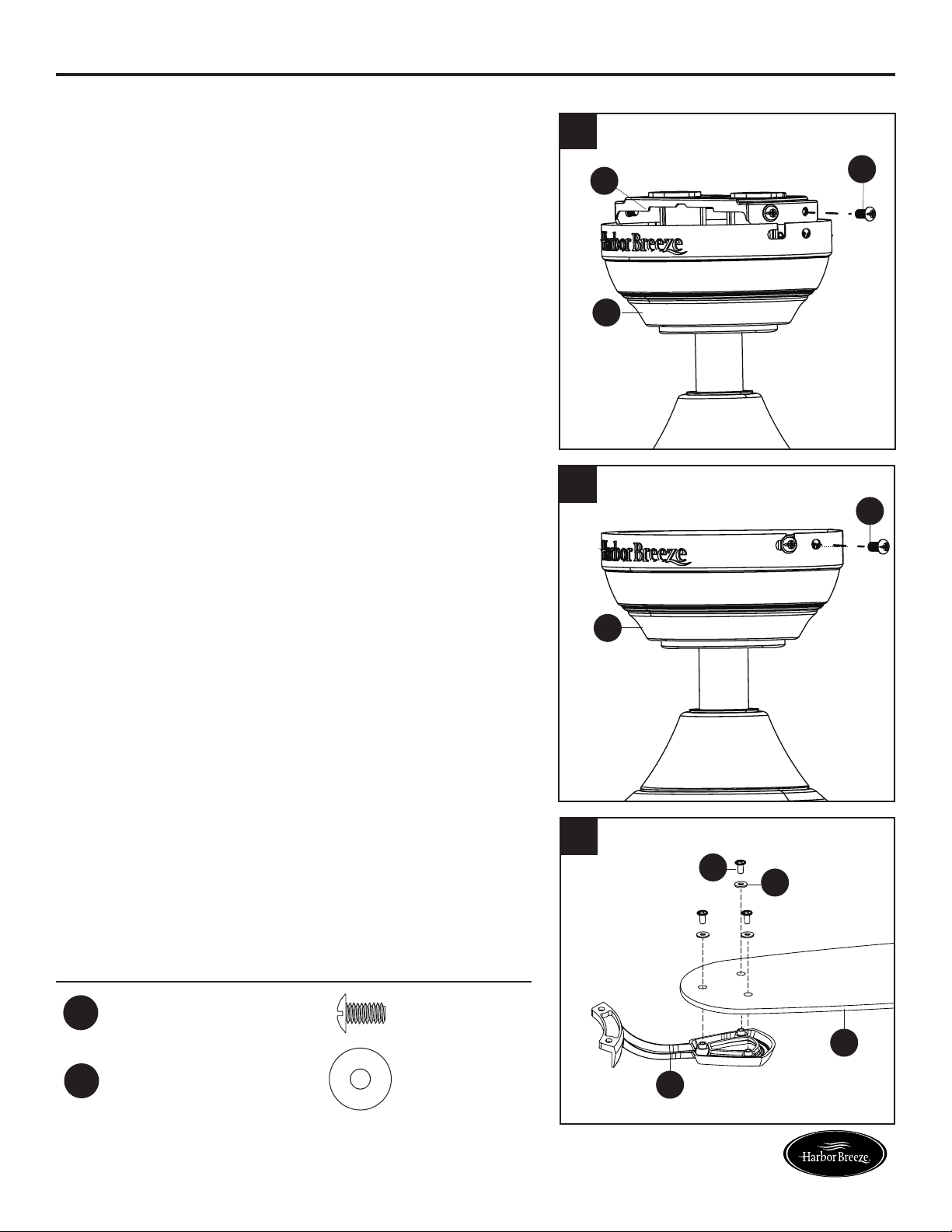
4. Install the blade arm (P) to the underside of the motor
assembly (G) with motor screws (R) previously removed
(Step 6, page 8). Tighten with Phillips screwdriver.
Repeat for each blade arm (P).
Note: If you wish to install the fan without the light kit
(J), proceed to Step 8.
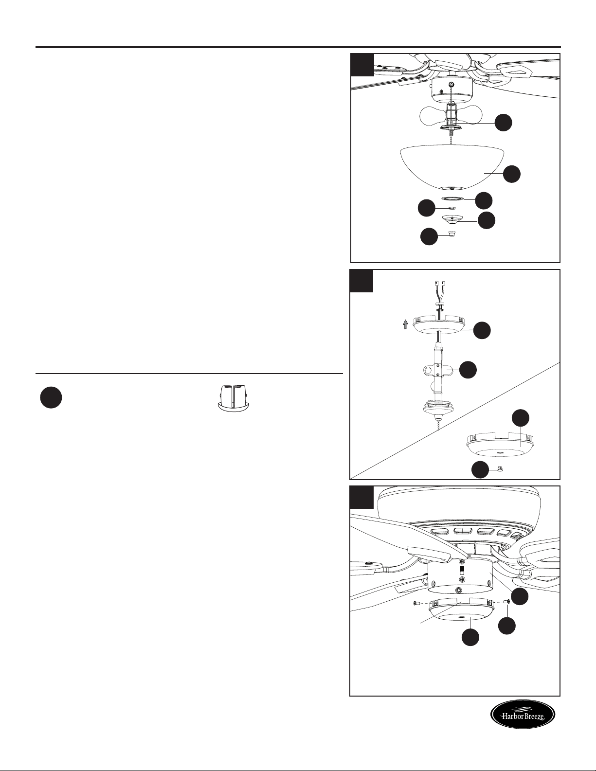
5. To install the light kit (J),rstremovethethreeswitch
housing screws (X) from the switch housing cap (I).
Then connect the single-pin connector from the switch
housing (H) to the single-pin connector from the light
kit (J) -- Black to Black and White to White. Secure the
switch housing cap (I) with light kit (J) to the switch
housing (H) using the previously removed switch
housing screws (X).
Note: Align the notch in the switch housing cap (I) with
the reverse switch on the switch housing (H).
6. Install the bulbs (M) into the sockets on the light kit (J).
IMPORTANT: Make sure you allow the bulbs (M) and
light kit (J) to cool before you replace the bulbs.
4
5
P
H
J
I
X
R
G
6
M
J
Notch
15
Lowes.com/harborbreeze
FINAL INSTALLATION
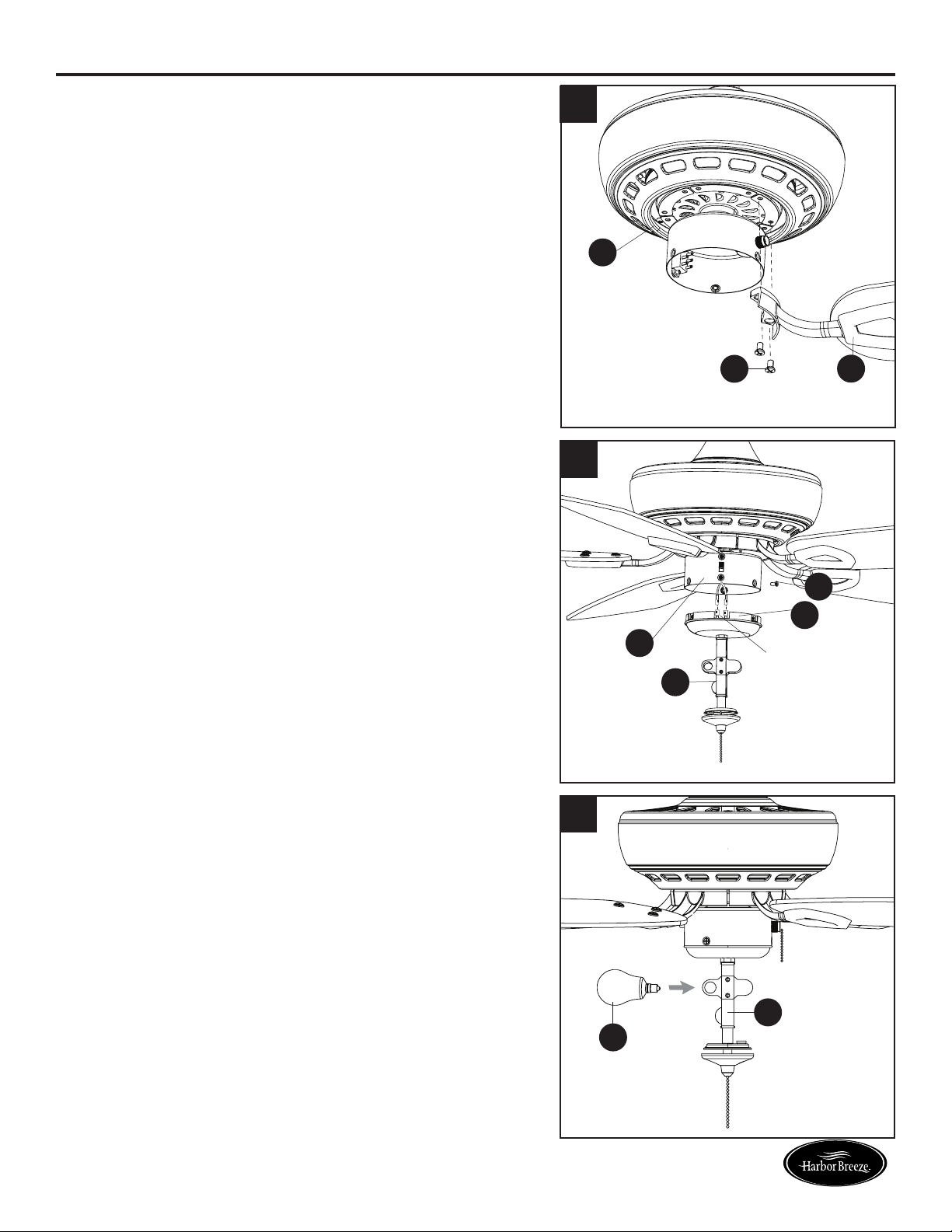
7.Removethepreassemblednial(L),nialcap(K),hex
nut (T) and rubber washer (U) from the light kit (J). Lift
the glass bowl (N) onto the threaded rod at the bottom
of the light kit (J).
Feed the pull chain coming from the grommet in the
light kit (J) through the off-center hole in the glass bowl
(N). Feed pull chain coming from the center of the light
kit (J) through the center hole in the glass bowl (N).
Secure glass bowl (N) with rubber washer (U) and hex
nut(T).Thenattachnialcap(K)andnial(L).
Proceed to Step 10.
8. To install the fan without the light kit (J), remove
the preassembled hex nut and lock washer from the
threaded rod on the inside of the switch housing cap (I).
Remove light kit (J) from the switch housing cap (I) and
discard, then install the plug button (EE) into the center
hole of the switch housing cap (I).
Hardware Used
EE
Plug Button x 1
9. Remove the three switch housing screws (X) from the
switch housing cap (I). Then, attach the switch housing
cap (I) to the switch housing (H) using the switch
housing screws (X).
Note: Align the notch in the switch housing cap (I) with
the reverse switch on the switch housing (H).
8
I
EE
I
J
U
N
J
T
K
L
7
I
X
H
9
Notch
16
Lowes.com/harborbreeze
H
a
r
b
o
r
B
r
e
e
z
e
H
a
r
b
o
r
B
r
e
e
z
e
FINAL INSTALLATION
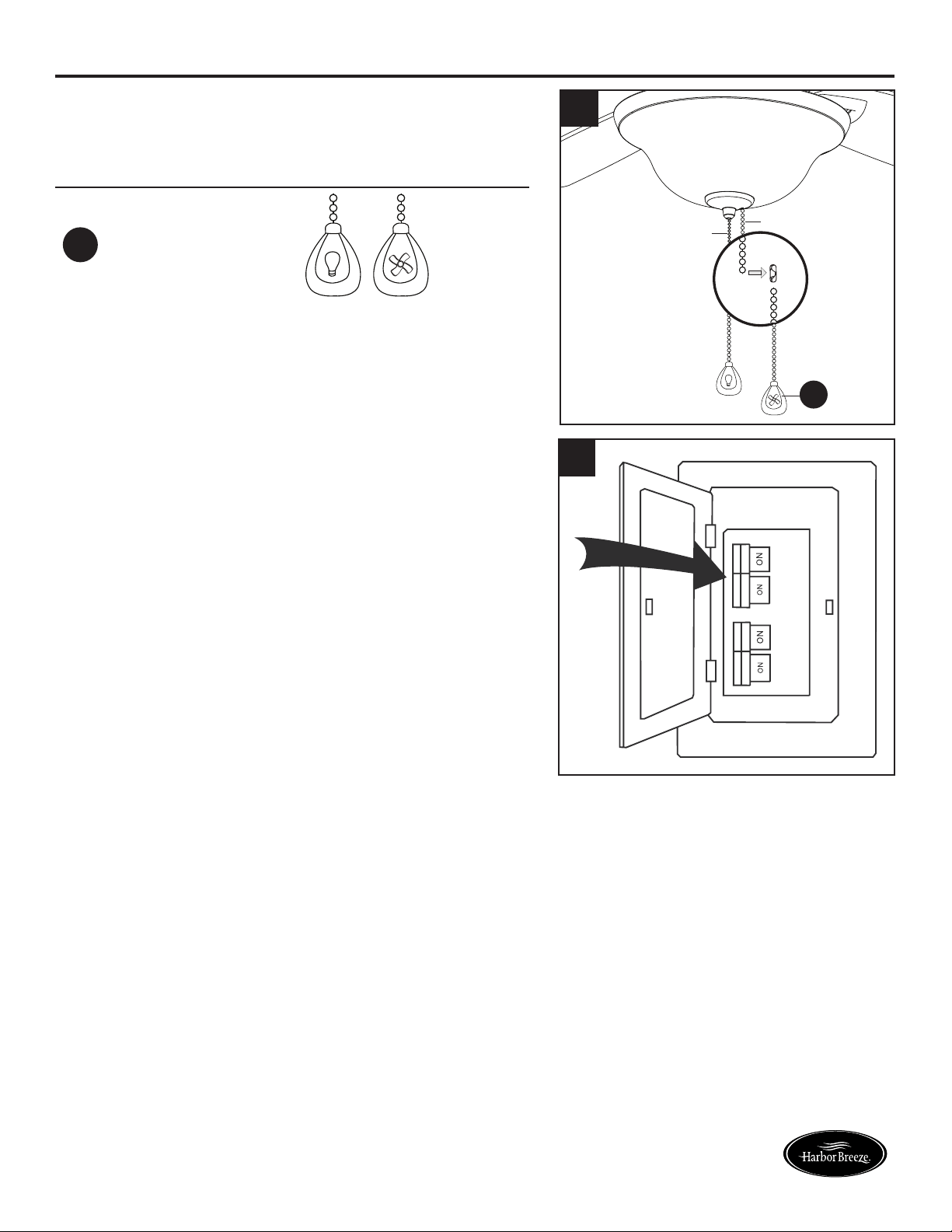
10. Attach the pull chain extensions (BB) or custom pull
chain extensions (not included) to the fan and light
pull chains (if applicable).
Hardware Used
BB
Pull Chain
Extension
x 2
11. Turn on power supply to the fan.
Assembly is complete.
10
11
BB
Fan Pull Chain
Light Pull Chain
H
a
r
b
o
r
B
r
e
e
z
e
H
a
r
b
o
r
B
r
e
e
z
e
17
Lowes.com/harborbreeze
OPERATING INSTRUCTIONS
1. The fan pull chain has four positions to control fan
speed. One pull is HIGH, two is MEDIUM, three is LOW
and four turns the fan OFF.
The light pull chain has two positions to control the light,
ON and OFF.
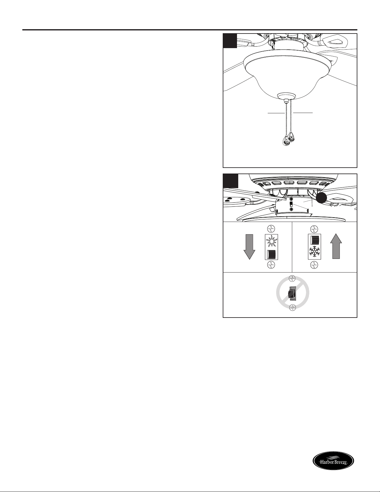
2. Use the fan reverse switch, located on the switch
housing (H), to optimize your fan for seasonal
performance.
Using a ceiling fan will allow you to raise your
thermostat setting in summer and lower your thermostat
setting in winter without feeling a difference in your
comfort.
Note: Wait for the fan to stop before moving the reverse
switch.
2a. In warmer weather, push the reverse switch down to
displayasunicon,whichwillresultindownwardairow
creating a wind chill effect.
2b. In cooler weather, push the reverse switch up to
displayasnowakeicon,whichwillresultinupward
airowthatcanhelpmovestagnant,hotairoffthe
ceiling area.
Important: The reverse switch must be set either
completely left or right in order for the fan to function
correctly. If the reverse switch is set in the middle
position, the fan will not operate (Fig. 2c).
Fig. 2a Fig. 2b
Fig. 2c
1
Fan Pull
Chain
Reverse Switch
Light Pull
Chain
H
2
18
Lowes.com/harborbreeze
CARE AND MAINTENANCE
At least twice each year, lower the canopy to check the downrod assembly, and then tighten all
screws on the fan. Clean the motor assembly with only a soft brush or lint-free cloth to avoid
scratchingthenish.Cleanthebladeswithalint-freecloth.
Bulb Replacement: Use 60-watt max. candelabra-base bulbs or CFL equivalent.
Important: Shut off the main power supply before you begin any maintenance task. Do not use water
or a damp cloth to clean the fan.
TROUBLESHOOTING
PROBLEM POSSIBLE CAUSE CORRECTIVE ACTION
The fan does not
move.
1. The reverse switch is not
engaged.
2. The wall switch is turned off.
3. The power is off or the fuse
(breaker) is blown.
4. There is a faulty wire
connection.
1. Firmly push the reverse switch
completely up or down.
2. Make sure the wall switch is turned on.
3. Turn the power on or check the fuse
(breaker).
4. Turn the power off and check all
connections at the ceiling outlet box.
The fan is noisy.
1. The blades are loose.
2. There is a cracked blade.
3. The wall control is not
compatible with the fan.
4. The outlet box is not secure.
5. The mounting bracket is not
secure.
1. Check and tighten all screws that
hold the fan blades to the blade
arms and the motor.
2. Replace the cracked blade.
3. Do not use a full range dimmer
switch to control the fan speed.
4. Ensure the outlet box is secured to
the building structure.
5. Ensure the mounting bracket is
secured to the outlet box and that
the screws are tight.
19
Lowes.com/harborbreeze
TROUBLESHOOTING
PROBLEM POSSIBLE CAUSE CORRECTIVE ACTION
There is excessive
wobbling.
1. The blades and/or blade arms
are loose.
2. The blades are unbalanced.
3. The fan mounting is not
secure.
4. The fan is too close to the
vaulted ceiling.
5. The set screws on the motor
assembly yoke is loose.
1. Check and tighten all screws that
hold the fan blades to the blade arms
and the blade arms to the motor.
2. Switch one blade with a blade from
the opposite side. Or balance the fan
using the blade balancing kit (Y).
3. Turn off the power. Loosen the
canopy and verify that the mounting
bracket is secure to the electrical
outletbox.Thebracketmustbeush
without movement against the outlet
box.
4. Use a longer downrod (sold
separately) or move the fan to
another location.
5. Lift up the yoke cover and tighten the
set screws on the yoke until secure.
The fan operates
correctly, but the
lights are not
working.
1. The bulbs are not installed
correctly.
2. The light kit wire plugs are not
connected properly.
3. There is a faulty wire
connection.
4. The total power of the lights
exceeds 190W.
1. Re-install the bulb(s).
2. Ensure the single-pin connectors in
the light kit are connected properly.
3. Turn the power off and check all
connections at the ceiling outlet box.
4. The fan comes with a 190W limiter.
When the total wattage of the lights
is over 190W, the lights do not work.
Replace with bulbs of lower wattage.

20
Lowes.com/harborbreeze
LIFETIME LIMITED WARRANTY
The manufacturer warrants this fan to be free from defects in workmanship and materials present at
time of shipment from the factory for a lifetime from the date of purchase by the original purchaser.
The retailer also warrants that all other fan parts, excluding any glass or plastic blades, to be free
from defects in workmanship and material at the time of shipment from the factory for a period of one
year after the date of purchase by the original purchaser. The manufacturer agrees to correct such
defects without charge or at its option replace the ceiling fan with a comparable or superior model.
To obtain warranty service, present a copy of the receipt as proof of purchase. All costs of removing
and reinstalling the product are your responsibility. Any damage to any part such as by accident or
misuseorimproperinstallationorbyafxinganyaccessories,isnotcoveredbythiswarranty.The
manufacturer assumes no responsibility whatsoever for fan installation during the limited lifetime
warranty. Any service performed by an unauthorized person will render the warranty invalid.
Duetovaryingclimateconditions,thiswarrantydoesnotcoveranychangesinbrassnish,including
rusting,pitting,corroding,tarnishingorpeeling.Brassnishesofthistypegivetheirlongestusefullife
when protected from varying weather conditions. Any glass provided with this fan is not covered by
the warranty.
Anyreplacementofdefectivepartsfromtheceilingfanmustbereportedwithintherstyearfromthe
date of purchase. For the balance of the warranty, call our customer service department for return
authorization and shipping instructions so that we may repair or replace the ceiling fan. Any fan or
parts returned improperly is the sole responsibility of the purchaser. There is no other expressed
warranty. The manufacturer disclaims any and all warranties. The duration of any implied warranty
whichcannotbedisclaimedislimitedtothetimeperiodasspeciedintheexpressedwarranty.The
manufacturer shall not be liable for incidental, consequential, or special damages arising out of or
in connection with product use or performance except as may otherwise be accorded by law. This
warrantygivesspeciclegalrights,andyoumayalsohaveotherrightswhichvaryfromstatetostate.
This warranty supersedes all prior warranties.
Note: A small amount of “wobble” is normal and should not be considered a defect.
Lowes.com/harborbreeze
21
Printed in China
Harbor Breeze® is a registered trademark
of LF, LLC. All Rights Reserved.
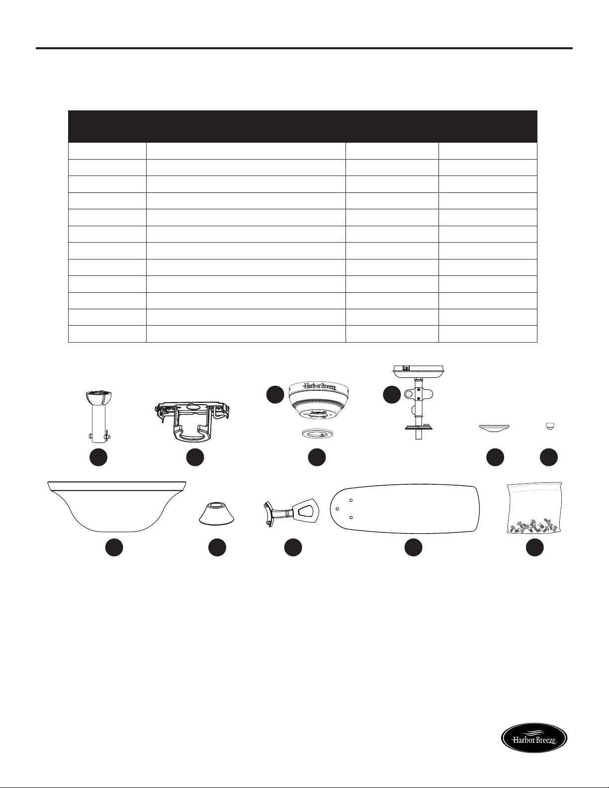
REPLACEMENT PARTS LIST
For replacement parts, call the customer service department at 1-800-643-0067, 8 a.m. - 6 p.m., EST,
Monday - Thursday, 8 a.m. - 5 p.m., EST, Friday.
PART DESCRIPTION
0747607
PART #
0747608
PART #
A Downrod 0747607-A 0747608-A
D Mounting Bracket 0747607-D 0747608-D
E Canopy 0747607-E 0747608-E
F Canopy Cover 0747607-F 0747608-F
J Light Kit 0747607-J 0747608-J
K Finial Cap 0747607-K 0747608-K
L Finial 0747607-L 0747608-L
N Glass Bowl 0747607-N 0747608-N
O Yoke Cover 0747607-O 0747608-O
P Blade Arm 0747607-P 0747608-P
Q Blade 0747607-Q 0747608-Q
HW Hardware Kit 0747607-HW 0747608-HW
9118•101615
D
E
A F
J
K L
N HWO P Q