Loading ...
Loading ...
Loading ...
En-5
Fig. 1 Fig.2
Fig.3 Fig.4
Fig.5 Fig.6
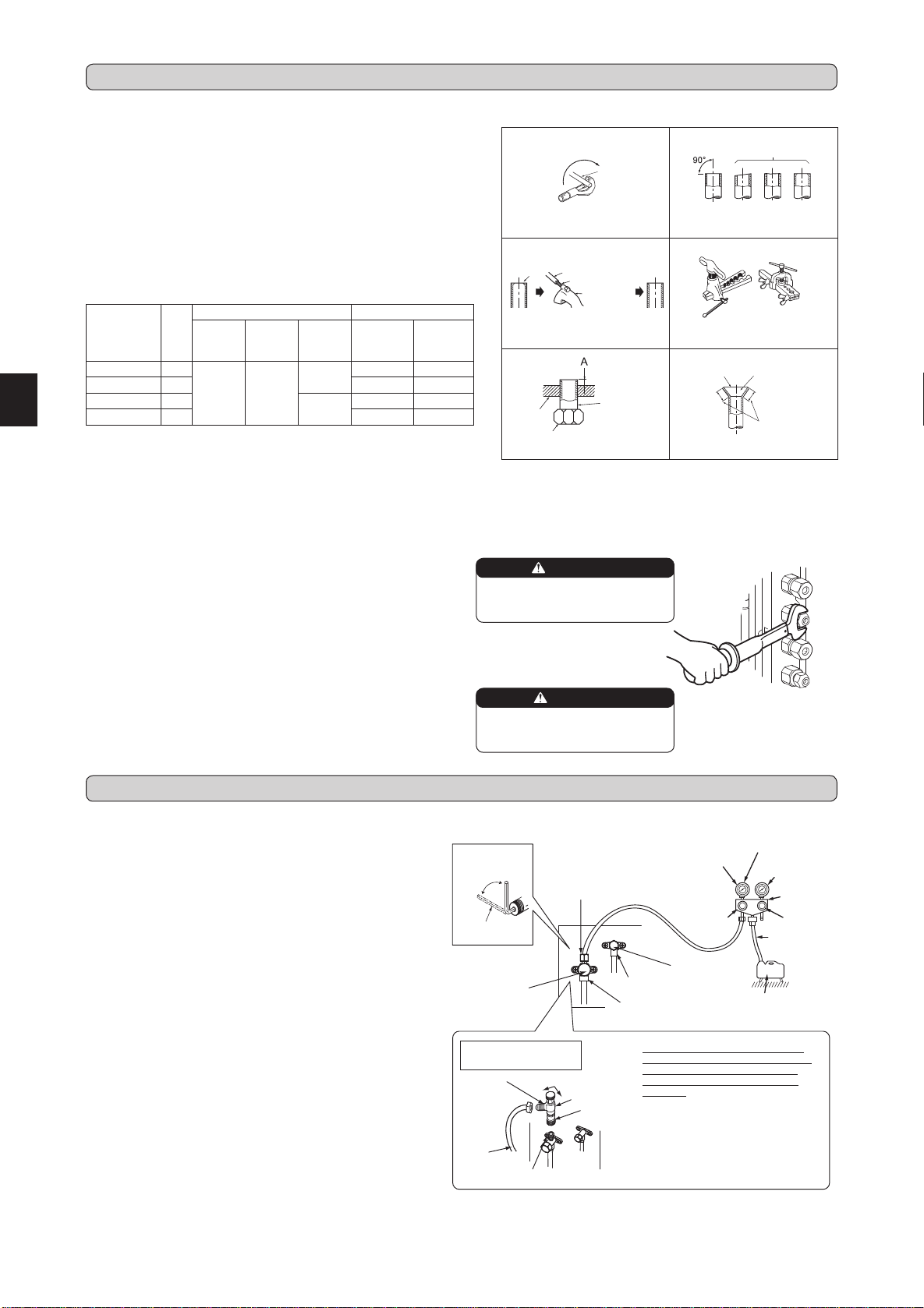
3-1. FLARING WORK
Pipediameter
(mm)
Nut
(mm)
A(mm) Tighteningtorque
Clutch
typetool
forR410A
Clutch
typetool
forR22
Wing nut
typetool
forR22
N•m kgf•cm
ø6.35(1/4”) 17
0to0.5 1.0to1.5
1.5to2.0
13.7to17.7 140to180
ø9.52(3/8”) 22 34.3to41.2 350to420
ø12.7(1/2”) 26
2.0to2.5
49.0to56.4 500to575
ø15.88(5/8”) 29 73.5to78.4 750to800
TiltedUnevenBurred
Good
No good
Burr
Copperpipe
Sparereamer
Pipecutter
Smooth all
around
Evenlength
all around
Inside is shin-
ingwithoutany
scratches.
Flare nut
Die
Copperpipe
Clutchtype
Flaring tool
Wingnuttype
3-2. PIPE CONNECTION
1)Applyathincoatofrefrigerationoil(G)tothearedendsofthepipes
andthepipeconnectionsoftheoutdoorunit.Donotapplyrefrigeration
oilonscrewthreads.Excessivetighteningtorquewillresultindamage
onthescrew.
2)Alignthecenterofthepipewiththatofthepipeconnectionsoftheoutdoor
unit,thenhandtightenthearenut3to4turns.
3)Tightenthearenutwithatorquewrenchasspeciedinthetable.
• Over-tighteningmaycausedamagetothearenut,resultinginrefriger-
antleakage.
• Besuretowrapinsulationaroundthepiping.Directcontactwiththe
barepipingmayresultinburnsorfrostbite.
3-3. INSULATION AND TAPING
1)Coverpipingjointswithpipecover.
2)Foroutdoorunitside,surelyinsulateeverypipingincludingvalves.
3)Usingpipingtape(E),applytapingstartingfromtheentryofoutdoorunit.
• Stoptheendofpipingtape(E)withtape(withadhesiveagentattached).
• Whenpipinghavetobearrangedthroughaboveceiling,closetorwhere
thetemperatureandhumidityarehigh,windadditionalcommercially
soldinsulationtopreventcondensation.
Copper
pipe
1)Cutthecopperpipecorrectlywithpipecutter.(Fig.1,2)
2)Completelyremoveallburrsfromthecutcrosssectionofpipe.(Fig.3)
• Aimthecopperpipedownwardwhileremovingburrstopreventburrs
fromdroppinginthepipe.
3)Removearenutsattachedtoindoorandoutdoorunits,thenputthem
onpipehavingcompletedburrremoval.(Notpossibletoputthemon
afteraringwork.)
4)Flaringwork(Fig.4,5).Firmlyholdcopperpipeinthedimensionshown
in the table. Select A mm from the table according to the tool selected.
5)Check
• ComparethearedworkwithFig.6.
• Ifareisnotedtobedefective,cutoffthearedsectionanddoaring
workagain.
WARNING
When installing the unit, securely
connect the refrigerant pipes before
starting the compressor.
CAUTION
When there are the ports which are
not used, make sure their nuts are
tightened securely.
4-1. PURGING PROCEDURES AND LEAK TEST
1)Removeserviceportcapofstopvalveonthesideoftheoutdoorunit
gaspipe.(Thestopvalvesarefullyclosedandcoveredincapsintheir
initialstate.)
2)Connectgaugemanifoldvalveandvacuumpumptoserviceportofstop
valveonthegaspipesideoftheoutdoorunit.
3)Runthevacuumpump.(Vacuumizeformorethan15minutes.)
4)Checkthevacuumwithgaugemanifoldvalve,thenclosegaugemanifold
valve,andstopthevacuumpump.
5)Leaveasitisforoneortwominutes.Makesurethepointerofgauge
manifoldvalveremainsinthesameposition.Conrmthatpressuregauge
shows-0.101MPa[Gauge](-760mmHg).
6)Removegaugemanifoldvalvequicklyfromserviceportofstopvalve.
7)Fullyopenallstopvalvesonthegaspipeandtheliquidpipe.Operating
withoutfullyopeninglowerstheperformanceandthiscausestrouble.
8)Referto1-2.,andchargetheprescribedamountofrefrigerantifneeded.
Besuretochargeslowlywithliquidrefrigerant.Otherwise,composition
oftherefrigerantinthesystemmaybechangedandaffectperformance
of the air conditioner.
9)Tightencapofserviceporttoobtaintheinitialstatus.
10
)Leaktest
Stopvalve
forGAS
Gaugemani-
foldvalve(for
R410A)
Compoundpressure
gauge(forR410A)
–0.101MPa
(–760mmHg)
Handle
Low
HandleHigh
Vacuumpump
(forR410A)
Chargehose
(forR410A)
*Close
*Open
Hexagonal
wrench
*4to5turns
Stopvalve
forLIQUID
Pressuregauge
(forR410A)
Precautionswhenus-
ingthecontrolvalve
Whenattachingthecontrolvalve
totheserviceport,valvecoremay
deformorloosenifexcesspres-
sureisapplied.Thismaycause
gasleak.
Serviceport
Chargehose
(forR410A)
Body Close
Open
Controlvalve
A
Whenattachingthecontrolvalveto
theserviceport,makesurethatthe
valvecoreisinclosedposition,and
then tighten partA. Do nottighten
partA orturnthebodywhenvalve
coreisinopenposition.
4. PURGING PROCEDURES, LEAK TEST, AND TEST RUN
Stopvalvecap
(Torque24.4to
30.4N•m,250to
310kgf•cm)
Serviceportcap
(Torque10to12N•m,
100to120kgf•cm)
Serviceportcap
(Torque10to12N•m,
100to120kgf•cm)
Stopvalvecap
(Torque21.5to
27.5N•m,220
to280kgf•cm)
3. FLARING WORK AND PIPE CONNECTION
BH79A274H01_en.indd 5 2016/03/23 10:42:18
Loading ...
Loading ...
Loading ...