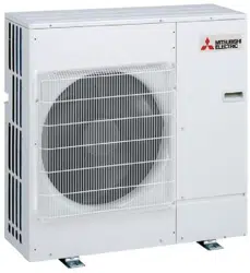
Split-type Air-Conditioner
MXZ-6E120VAD
English
Installation Manual
For INSTALLER
• This manual only describes the installation of outdoor unit.
When installing the indoor unit, refer to the installation manual of indoor unit.
BH79A274H01_en.indd 1 2016/03/23 10:42:14
En-1
1-1. THE FOLLOWING SHOULD ALWAYS BE OBSERVED FOR SAFETY
• Besuretoread“THEFOLLOWINGSHOULDALWAYSBEOBSERVEDFORSAFETY”beforeinstallingtheairconditioner.
• Besuretoobservethewarningsandcautionsspeciedhereastheyincludeimportantitemsrelatedtosafety.
• Afterreadingthismanual,besuretokeepittogetherwiththeOPERATINGINSTRUCTIONSforfuturereference.
• EquipmentcomplyingwithIEC/EN61000-3-12.
1-2. SPECIFICATIONS
Model
Powersupply*1 Wirespecications*2 Pipelengthandheightdifference
*3,*4,*5,*6,*7,*8
Rated
Voltage
Fre-
quency
Breaker
capacity
Power
supply
Indoor/outdoor
connectingwire
Max.pipe
lengthper
indoorunit/for
multi-system
Max. height
difference*9
Max. no. of bends
perindoorunit/
for multi system
Refrigerant
adjustment
A*10
MXZ-6E120VAD 230V 50Hz 32A
3-core
4.0mm
2
4-core
1.0/1.5mm
2
25m/80m 15m 25/80 20g/m
*1 Connecttothepowerswitchwhichhasagapof3mmormorewhenopen
tointerruptthesourcepowerphase.(Whenthepowerswitchisshutoff,it
mustinterruptallphases.)
*2 Usewiresinconformitywithdesign60245IEC57.Usetheindoor/outdoor
connectingwireinconformitywiththewirespecicationsspeciedinthe
installation manual of the indoor unit.
*3 Neverusepipeswiththicknesslessthanspecied.Thepressureresistance
willbeinsufcient.
*4 Useacopperpipeoracopper-alloyseamlesspipe.
*5 Becarefulnottocrushorbendthepipeduringpipebending.
*6 Refrigerantpipebendingradiusmustbe100mmormore.
*7 Insulationmaterial:Heatresistingfoamplastic0.045specicgravity
*8 Besuretousetheinsulationofspeciedthickness.Excessivethickness
maycauseincorrectinstallationoftheindoorunitandinsufcientthickness
maycausedewdrippage.
*
9
If the outdoor unit is installed higher than the indoor unit, max. height
differenceisreducedto10m.
*
10
Ifpipelengthexceeds30m,additionalrefrigerant(R410A)chargeisre-
quired.(Noadditionalchargeisrequiredforpipelengthlessthan30m.)
Additionalrefrigerant=A×(pipelength(m)-30)
Required Tools for Installation
Phillipsscrewdriver
Level
Scale
Utilityknifeorscissors
Torquewrench
Wrench(orspanner)
4mmhexagonalwrench
FlaretoolforR410A
GaugemanifoldforR410A
VacuumpumpforR410A
ChargehoseforR410A
Pipecutterwithreamer
ENGLISH
CONTENTS
1.BEFOREINSTALLATION ............................................................1
2.OUTDOORUNITINSTALLATION ...............................................4
3.FLARINGWORKANDPIPECONNECTION ...............................5
4.PURGINGPROCEDURES,LEAKTEST,ANDTESTRUN .........5
5.PUMPINGDOWN ........................................................................ 7
CAUTION
(Couldleadtoseriousinjuryinparticularenvironmentswhenoperatedincorrectly.)
n Do not install the unit by yourself (user).
Incompleteinstallationcouldcausereorelectricshock,injuryduetotheunit
falling,orleakageofwater.Consultthedealerfromwhomyoupurchased
theunitoraqualiedinstaller.
n Perform the installation securely referring to the installation manual.
Incompleteinstallationcouldcausere,electricshock,injuryduetothe
unitfalling,orleakageofwater.
n When installing the unit, use appropriate protective equipment and
tools for safety.
Failure to do so could cause injury.
n Install the unit securely in a place which can bear the weight of the
unit.
Iftheinstallationlocationcannotbeartheweightoftheunit,theunitcould
fall causing injury.
n Electrical work should be performed by a qualied, experienced electri-
cian, according to the installation manual. Be sure to use an exclusive
circuit. Do not connect other electrical appliances to the circuit.
If thecapacity of the power circuit is insufcient or there is incomplete
electricalwork,itcouldresultinareoranelectricshock.
n Do not damage the wires by applying excessive pressure with parts
or screws.
Damagedwirescouldcausereorelectricshock.
n Be sure to cut off the main power in case of setting up the indoor P.C.
board or wiring works.
Failuretodosocouldcauseelectricshock.
n Use the specied wires to connect the indoor and outdoor units
securely and attach the wires rmly to the terminal block connecting
sections so the stress of the wires is not applied to the sections. Do
not extend the wires, or use intermediate connection.
Incompleteconnectingandsecuringcouldcausere.
n Do not install the unit in a place where inammable gas may leak.
Ifgasleaksandaccumulatesintheareaaroundtheunit,itcouldcausean
explosion.
n Do not use intermediate connection of the power cord or the extension
cord and do not connect many devices to one AC outlet.
Itcouldcauseareoranelectricshockduetodefectivecontact,defective
insulation,exceedingthepermissiblecurrent,etc.
n Be sure to use the parts provided or specied parts for the installation
work.
Theuseofdefectivepartscouldcauseaninjuryorleakageofwaterdue
toare,anelectricshock,theunitfalling,etc.
n When plugging the power supply plug into the outlet, make sure that
there is no dust, clogging, or loose parts in both the outlet and the
plug. Make sure that the power supply plug is pushed completely into
the outlet.
Ifthereisdust,clogging,orloosepartsonthepowersupplyplugorthe
outlet,itcouldcauseelectricshockorre.Ifloosepartsarefoundonthe
powersupplyplug,replaceit.
n Attach the electrical cover to the indoor unit and the service panel
to the outdoor unit securely.
Iftheelectricalcoveroftheindoorunitand/ortheservicepanelofthe
outdoorunitarenotattachedsecurely,itcouldresultinareoranelectric
shockduetodust,water,etc.
n When installing, relocating, or servicing the unit, make sure that no
substance other than the specied refrigerant (R410A) enters the
refrigerant circuit.
Anypresenceofforeignsubstancesuchasaircancauseabnormalpres-
sureriseandmayresultinexplosionorinjury.Theuseofanyrefrigerant
otherthan thatspeciedfor the systemwillcause mechanicalfailure,
systemmalfunction,orunitbreakdown.Intheworstcase,thiscouldlead
toaseriousimpedimenttosecuringproductsafety.
n Do not discharge the refrigerant into the atmosphere. If refrigerant
leaks during installation, ventilate the room.
Ifrefrigerantcomesincontactwithare,harmfulgascouldbegenerated.
n Check that the refrigerant gas does not leak after installation has
been completed.
Ifrefrigerantgasleaksindoors,andcomesintocontactwiththeameofa
fanheater,spaceheater,stove,etc.,harmfulsubstanceswillbegenerated.
n Use appropriate tools and piping materials for installation.
ThepressureofR410Ais1.6timesmorethanR22.Notusingappropriate
toolsormaterialsandincompleteinstallationcouldcausethepipesto
burst or injury.
n When pumping down the refrigerant, stop the compressor before
disconnecting the refrigerant pipes.
Iftherefrigerantpipesaredisconnectedwhilethecompressorisrunning
andthestopvalveisopen,aircouldbedrawninandthepressureinthe
refrigeration cycle could become abnormally high. This could cause the
pipestoburstorinjury.
n When installing the unit, securely connect the refrigerant pipes
before starting the compressor.
Ifthecompressorisstartedbeforetherefrigerantpipesareconnected
andwhenthestopvalveisopen,aircouldbedrawninandthepressure
in the refrigeration cycle could become abnormally high. This could cause
thepipestoburstorinjury.
n Fasten a are nut with a torque wrench as specied in this manual.
Iffastenedtootight,aarenutmaybreakafteralongperiodandcause
refrigerantleakage.
n The unit shall be installed in accordance with national wiring regula-
tions.
n Earth the unit correctly.
Donotconnecttheearthtoagaspipe,waterpipe,lightningrodortel-
ephoneearth.Defectiveearthingcouldcauseelectricshock.
n Be sure to install an earth leakage breaker.
Failuretoinstallanearthleakagebreakermayresultinelectricshockorre.
n Perform the drainage/piping work securely according to the installation
manual.
Ifthereisdefectinthedrainage/pipingwork,watercoulddropfromtheunit,
soakinganddamaginghouseholdgoods.
n Do not touch the air inlet or the aluminum ns of the outdoor unit.
This could cause injury.
n Do not install the outdoor unit where small animals may live.
Ifsmallanimalsenterandtouchtheelectricpartsinsidetheunit,itcould
causeamalfunction,smokeemission,orre.Also,adviseusertokeep
the area around the unit clean.
WARNING
(Couldleadtodeath,seriousinjury,etc.)
1. BEFORE INSTALLATION
BH79A274H01_en.indd 1 2016/03/23 10:42:15
En-2
1-3. SELECTING OPTIONAL DIFFERENT-DIAMETER JOINTS
Ifthediameterofconnectionpipedoesnotmatchtheportsizeofoutdoorunit,useoptionaldifferent-diameterjointsaccordingtothefollowingtable.
Portsizeofoutdoorunit Optionaldifferent-diameterjoints(portsizeofoutdoorunit
→
diameterofconnectionpipe)
MXZ-6E Liquid/Gas
6.35(1/4)
→
9.52(3/8):PAC-493PI
9.52(3/8)
→
12.7(1/2):MAC-A454JP
9.52(3/8)
→
15.88(5/8):PAC-SG76RJ
12.7(1/2)
→
9.52(3/8):MAC-A455JP
12.7(1/2)
→
15.88(5/8):MAC-A456JP
Refertotheinstallationmanualofindoorunitforthediameterofconnectionpipeofindoorunit.
AUNIT 6.35(1/4)/12.7(1/2)
B-FUNIT 6.35(1/4)/9.52(3/8)
1-4. SELECTING THE INSTALLATION LOCATION
• Whereitisnotexposedtostrongwind.
• Whereairowisgoodanddustless.
• Whererainordirectsunshinecanbeavoidedasmuchaspossible.
• Whereneighboursarenotannoyedbyoperationsoundorhotair.
• Whererigidwallorsupportisavailabletopreventtheincreaseofopera-
tionsoundorvibration.
• Wherethereisnoriskofcombustiblegasleakage.
• Wheninstallingtheunit,besuretosecuretheunitlegs.
• Whereitisatleast3mawayfromtheantennaofTVsetorradio.Opera-
tionoftheairconditionermayinterferewithradioorTVreceptioninareas
wherereceptionisweak.Anampliermayberequiredfortheaffected
device.
• Installtheunithorizontally.
• Pleaseinstallitinanareanotaffectedbysnowfallorblowingsnow.In
areaswithheavysnow,pleaseinstallacanopy,apedestaland/orsome
bafeboards.
Note:
Itis advisabletomake a pipingloop near outdoorunit so asto reduce
vibrationtransmittedfromthere.
Note:
Whenoperatingtheairconditionerinlowoutsidetemperature,besure
tofollowtheinstructionsdescribedbelow.
• Neverinstalltheoutdoorunitinaplacewhereitsairinlet/outletside
maybeexposeddirectlytowind.
• Topreventexposuretowind,installtheoutdoorunitwithitsairinlet
sidefacingthewall.
•
Topreventexposuretowind,itisrecommendedtoinstallabafeboard
on the air outlet side of the outdoor unit.
Avoidthefollowingplacesforinstallationwhereairconditionertrouble
is liable to occur.
• Whereammablegascouldleak.
• Wherethereismuchmachineoil.
• Saltyplacessuchastheseaside.
• Wheresuldegasisgenerated suchashotspring,sewage,waste
water.
• Wherethereishigh-frequencyorwirelessequipment.
• WherethereisemissionofhighlevelsofVOCs,includingphthalate
compounds,formaldehyde,etc.,whichmaycausechemicalcracking.
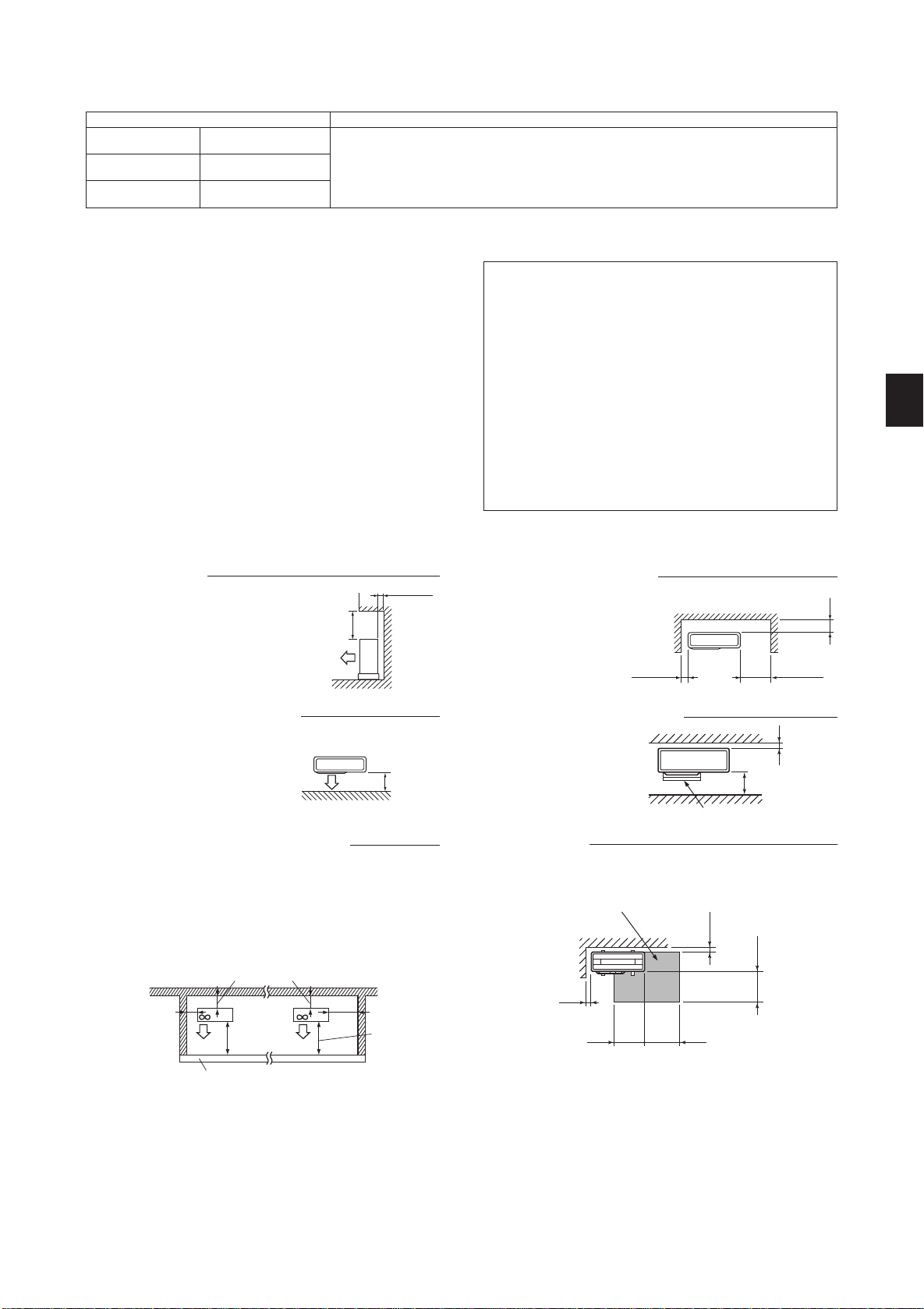
(Unit:mm(inch))
3. Obstacles in front (blowing) only
When there is an obstacle in front of
theunitasshowninthegure,open
spaceabove,behind,andonthesides
oftheunitisrequired.
2. Front (blowing) side open
As long as space indicated
in the figure is provided, it
is allowed to install the unit
where obstaclesare behind
and on the sides of the unit.
(Noobstacleabovetheunit)
FREE SPACE REQUIRED AROUND OUTDOOR UNIT
500ormore
200ormore
350ormore100ormore
1. Obstacles above
When there is no obstacle in front and
onthesidesof the unit, itisallowed
toinstalltheunitwhereanobstacleis
abovetheunitonlyifthespaceshown
inthegureisprovided.
100ormore
500ormore
100ormore
Servicespace
350ormore
350ormore
6. Service space
Providespaceforserviceandmaintenanceasshowninthegure.
500ormore
100ormore
• Wheninstallingtheunitinanareathatisenclosedwithwallssuch
asaverandah,besuretohaveenoughspaceasshownbelow.
Inthiscase,theairconditioningcapacityandpowerconsumption
might deteriorate.
• Whenthereisalackofairoworthereisapossibilityofbecoming
shortcycle,installanoutletguideandmakesurethereisenough
spacebehindoftheunit.
• Wheninstallingtwoormoreunits,donotinstalltheunitsinfrontor
behind each other.
100ormore
200ormore
350ormore
500ormore
500ormore
(Unit:mm)
5. Obstacles in front, behind and on side(s)
4. Obstacles in front and behind
The unit can be used by at-
tachinganoptionaloutdoor
blowingguide(PAC-
SH96SG-E)(butbothsides
andtopareopen).
100ormore
500ormore
Blowingguide(PAC-SH96SG-E)
Heightoftheobstacleis1200orless
BH79A274H01_en.indd 2 2016/03/23 10:42:15
En-3
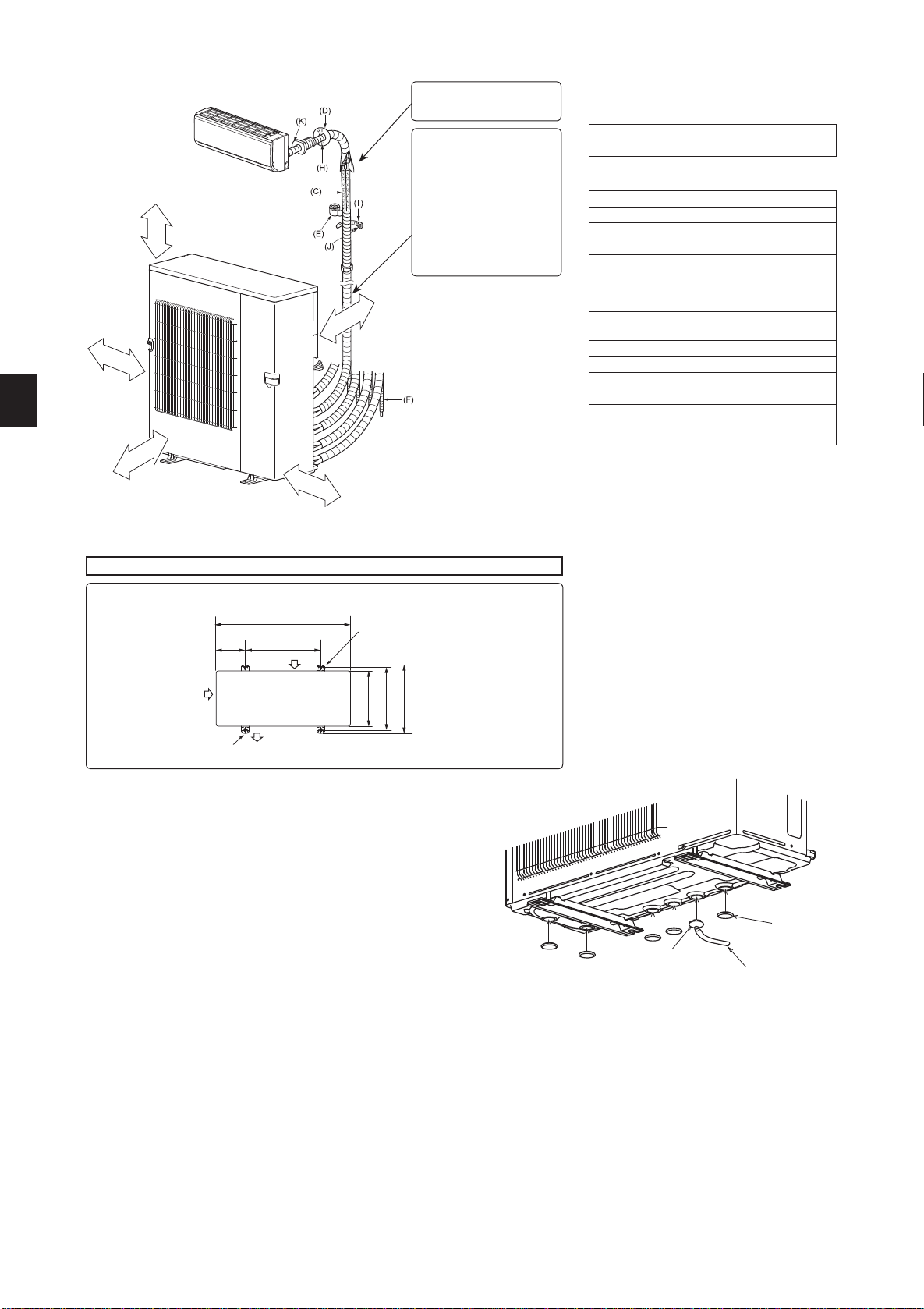
1-5. INSTALLATION DIAGRAM
Unitsshouldbeinstalledbylicensedcontractoraccordingtolocalcoderequirements.
After the leak test, apply insulat-
ing material tightly so that there
isnogap.
ACCESSORIES
Checkthefollowingpartsbeforeinstallation.
(1) Drainsocket 1
(2) Draincap 5
PARTS TO BE PROVIDED AT YOUR SITE
(A) Powersupplycord* 1
(B) Indoor/outdoorunitconnectingwire* 1
(C) Extensionpipe 1
(D) Wallholecover 1
(E) Pipingtape 1
(F)
Extension drain hose
(orsoftPVChose,15mminner
diameterorhardPVCpipeVP16)
1
(G) Refrigeration oil
Little
amount
(H) Putty 1
(I) Pipexingband 2to7
(J) Fixingscrewfor(I) 2to7
(K) Wallholesleeve 1
(L)
SoftPVChose,15mminner
diameterorhardPVCpipeVP16
fordrainsocket(1)
1
* Note:
Place indoor/outdoor unit connecting wire (B)and
powersupplycord (A) atleast1maway from the
TVantennawire.
The“Q’ty”for(B)to(K)intheabovetableisquantity
tobeusedperindoorunit.
More than
100mm
Openasarule
Morethan500mm
if the front and both
sidesareopen
Morethan100mm
Morethan200mmifthereare
obstacles to both sides
Openasarule
Morethan500mmiftheback,
bothsidesandtopareopen
Morethan350mm
Outdoor unit installation
Air inlet
Air outlet
Air inlet
950mm
600mm
175
mm
2-U-shapenotchedholes
(BaseboltM10)
330mm
2-12mm×36mm
ovalholes(BaseboltM10)
370mm
417mm
Whenthepipingistobeattachedto
awallcontainingmetals(tinplated)
or metal netting, use a chemically
treated wooden piece20 mm or
thicker between the wall and the
pipingorwrap7to8turnsofinsula-
tionvinyltapearoundthepiping.
To use existing piping, perform
COOL operation for30 minutes
and pump down before removing
theoldairconditioner.Remakeare
accordingtothedimensionfornew
refrigerant.
1-6. DRAIN PIPING FOR OUTDOOR UNIT
1) Performthedrainpipingworkonlywhendrainingfromoneplace.
2) Providedrainpipingbeforeindoorandoutdoorpipingconnection.
3) Attachthedrainsockettooneoftheseveraldrainholes.
Fixthedrainsocketintothedrainholeofthebaseusingthecatchestosecureitin
place.
4) ConnectthesoftPVChoseI.D.15mmasshownintheillustration.
5) Makesuretoprovidedrainpipingwithadownhillgradeforeasydrainow.
6) Gluethedraincapstoclosealltheotherunnecessaryholeswiththeglue(Prepare
intheeld).
Note:
Applythegluesecurely,astheglue(Prepareintheeld)willworkassealtoprevent
waterfromleaking.
Usetheadhesivefortherubberandmetal.
Attention
The outdoorunit is providedwith several holes for drainage at the bottom to make
drainage easier.
Thedrainsocketisusedtoclosetheunnecessaryholesandcentralizethedrainage
whenusingthedraintubeattheinstallationplace.
Donottousethedrainsocketincoldregion.Thedraintubecanbefrozen.
(1)Drainsocket
(L)SoftPVChose
(2)Draincap
BH79A274H01_en.indd 3 2016/03/23 10:42:15
En-4
A B C
D E F
A B C
D E F
A B C
E F
A B C
D E F
A B C
D D E F
DRDRDRDRDR
P P P P P
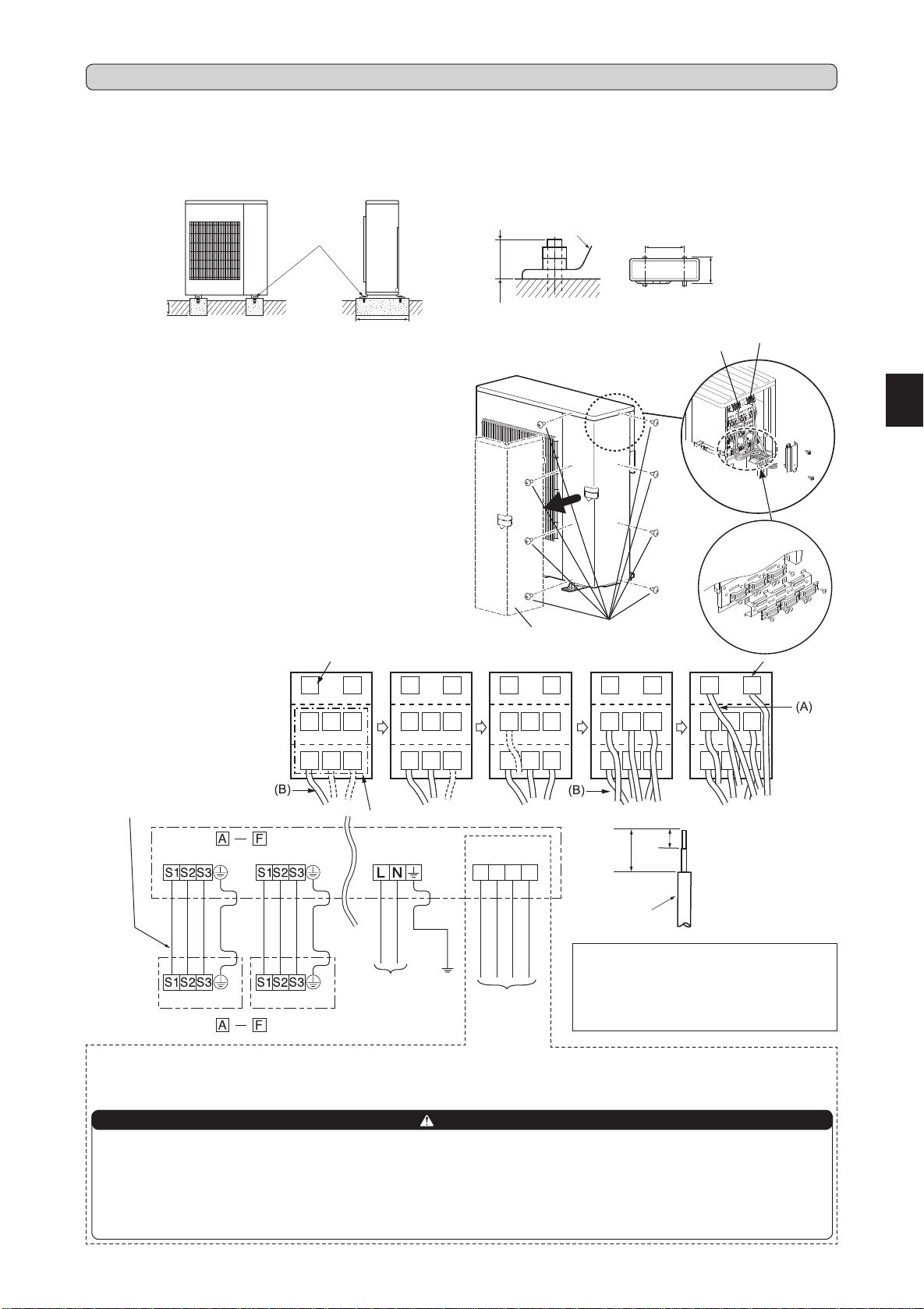
2-1. INSTALLING THE UNIT
Fixherewith
M10bolts.
Makethesetting
depthdeeper.
Makewidthwider.
Anchor leg
25orless
Anchor bolt length
Anchorboltpitch
(Unit:mm)
2-2. CONNECTING WIRES FOR OUTDOOR UNIT
Terminalblock
forpowersupply
• Besuretoxtheunit’slegswithboltswheninstallingit.
• Besuretoinstalltheunitrmlytoensurethatitdoesnotfallbyanearthquakeoragust.
• Refertothegureintherightforconcretefoundation.
• Donotusethedrainsocketandthedraincapsinthecoldregion.
Drainmayfreezeanditmakesthefanstop.
• Removethetapeonthepanelwhenopeningthepackage.(DONOTremovetheLABELSonthepanel.)
1)Removetheservicepanel.
2)Loosenterminalscrew,andconnectindoor/outdoorunitconnectingwire
(B)fromtheindoorunitcorrectlyontheterminalblock.Becarefulnot
tomakemis-wiring.Fixthewiretotheterminalblocksecurelysothat
nopartofitscoreisappeared,andnoexternalforceisconveyedtothe
connectingsectionoftheterminalblock.
3)Firmlytightentheterminalscrewstopreventthemfromloosening.After
tightening,pullthewireslightlytoconrmthattheydonotmove.
4)Perform2)and3)foreachindoorunit.
5)Connectpowersupplycord(A).
6)Fixindoor/outdoorunitconnectingwire(B)andpowersupplycord(A)
withthecableclamps.
7)Closetheservicepanelsecurely.Makesurethat3-2.PIPECONNEC-
TIONiscompleted.
• After making connectionsbetweenbothpowersupplycord(A) and
indoor/outdoorunitconnectingwire(B),besuretoxbothcableand
wirewithcableclamps.
Connectingorder
• Connect theterminal block in
followingorder.
A
→
B
→
C
→
D
→
E
→
F
→
P
→
DR
Terminalblockforindoor/outdoorunit
Cableclamps
600
370
Servicepanel
Screws
Note:
• Removingthehandleincreasestheeffectivenessofthewiringoperation.
• Besuretoreinstallthehandle.
2. OUTDOOR UNIT INSTALLATION
Terminalblock
forDREDInterface
DREDInterface
Powersupply
35mm
15mm
Leadwire
• Besuretoattacheachscrewtoitscorrespondent
terminalwhensecuringthecordand/orthewireto
theterminalblock.
• Makeearthwirealittlelongerthanothers.
(Morethan35mm)
• Forfutureservicing,giveextralengthtothecon-
nectingwires.
1 2 3 C
<OUTDOORUNIT>
Indoor/outdoorunit
connectingwire
<INDOORUNIT>
Terminalblock
Terminalblock Terminalblock
Terminalblockfor
powersupply
Terminalblock
<INDOORUNIT>
POWERSUPPLY
~/N230V50Hz
ThisunithasdemandresponsecapabilitywhichiscompliantwithAS/NZS4755.3.1.Toactivatethisfunction,youneedtomakeacontractwithremote
agentssuchaselectricsupplycompany,thenthisunitshouldbeconnectedtoDemandresponseenablingdevise(DRED).Forfurtherinformation,
consultyourdealer.Thisunitsupports3DemandResponseModes(DRMs):DRM1,DRM2andDRM3.
CAUTION
•Topreventmalfunctioncausedbynoise,routethecordconnectingthisunittoDREDandthepowersupplycordasparallelaspossible.
•Donotconnectthedemandcontroltransmissioncabletotheterminalblockforpowersupply.
•Donotpull,extremelybendorapplystrongpressureonthewiretopreventfailure.
•DonotscrewDREDtooutdoorunit.
•DonotputDREDinoutdoorunit.
•Secureelectricalwiringaboveclamp.
•DonotgetDREDwirecaughtintheservicepanel.
1:DRM1
2:DRM2
3:DRM3
C:COMMON
AS/NZS4755
terminalblock
BH79A274H01_en.indd 4 2016/03/23 10:42:17
En-5
Fig. 1 Fig.2
Fig.3 Fig.4
Fig.5 Fig.6
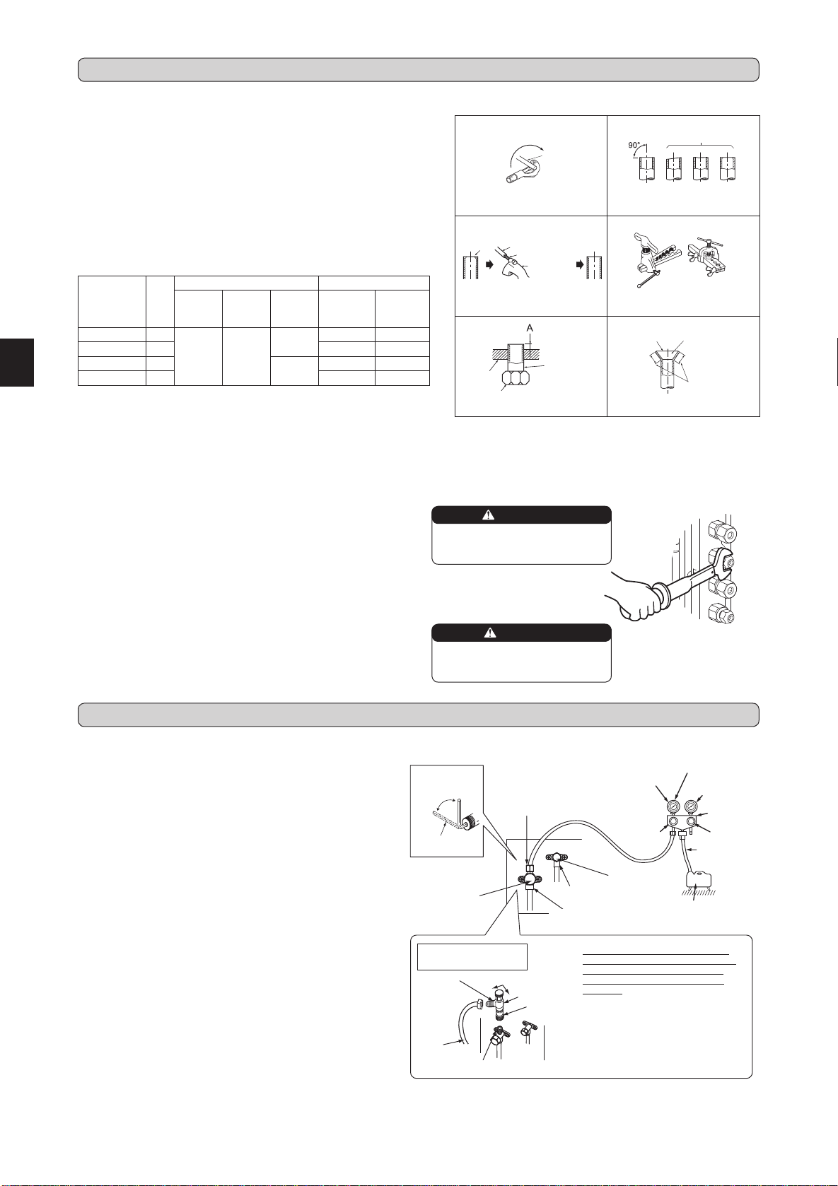
3-1. FLARING WORK
Pipediameter
(mm)
Nut
(mm)
A(mm) Tighteningtorque
Clutch
typetool
forR410A
Clutch
typetool
forR22
Wing nut
typetool
forR22
N•m kgf•cm
ø6.35(1/4”) 17
0to0.5 1.0to1.5
1.5to2.0
13.7to17.7 140to180
ø9.52(3/8”) 22 34.3to41.2 350to420
ø12.7(1/2”) 26
2.0to2.5
49.0to56.4 500to575
ø15.88(5/8”) 29 73.5to78.4 750to800
TiltedUnevenBurred
Good
No good
Burr
Copperpipe
Sparereamer
Pipecutter
Smooth all
around
Evenlength
all around
Inside is shin-
ingwithoutany
scratches.
Flare nut
Die
Copperpipe
Clutchtype
Flaring tool
Wingnuttype
3-2. PIPE CONNECTION
1)Applyathincoatofrefrigerationoil(G)tothearedendsofthepipes
andthepipeconnectionsoftheoutdoorunit.Donotapplyrefrigeration
oilonscrewthreads.Excessivetighteningtorquewillresultindamage
onthescrew.
2)Alignthecenterofthepipewiththatofthepipeconnectionsoftheoutdoor
unit,thenhandtightenthearenut3to4turns.
3)Tightenthearenutwithatorquewrenchasspeciedinthetable.
• Over-tighteningmaycausedamagetothearenut,resultinginrefriger-
antleakage.
• Besuretowrapinsulationaroundthepiping.Directcontactwiththe
barepipingmayresultinburnsorfrostbite.
3-3. INSULATION AND TAPING
1)Coverpipingjointswithpipecover.
2)Foroutdoorunitside,surelyinsulateeverypipingincludingvalves.
3)Usingpipingtape(E),applytapingstartingfromtheentryofoutdoorunit.
• Stoptheendofpipingtape(E)withtape(withadhesiveagentattached).
• Whenpipinghavetobearrangedthroughaboveceiling,closetorwhere
thetemperatureandhumidityarehigh,windadditionalcommercially
soldinsulationtopreventcondensation.
Copper
pipe
1)Cutthecopperpipecorrectlywithpipecutter.(Fig.1,2)
2)Completelyremoveallburrsfromthecutcrosssectionofpipe.(Fig.3)
• Aimthecopperpipedownwardwhileremovingburrstopreventburrs
fromdroppinginthepipe.
3)Removearenutsattachedtoindoorandoutdoorunits,thenputthem
onpipehavingcompletedburrremoval.(Notpossibletoputthemon
afteraringwork.)
4)Flaringwork(Fig.4,5).Firmlyholdcopperpipeinthedimensionshown
in the table. Select A mm from the table according to the tool selected.
5)Check
• ComparethearedworkwithFig.6.
• Ifareisnotedtobedefective,cutoffthearedsectionanddoaring
workagain.
WARNING
When installing the unit, securely
connect the refrigerant pipes before
starting the compressor.
CAUTION
When there are the ports which are
not used, make sure their nuts are
tightened securely.
4-1. PURGING PROCEDURES AND LEAK TEST
1)Removeserviceportcapofstopvalveonthesideoftheoutdoorunit
gaspipe.(Thestopvalvesarefullyclosedandcoveredincapsintheir
initialstate.)
2)Connectgaugemanifoldvalveandvacuumpumptoserviceportofstop
valveonthegaspipesideoftheoutdoorunit.
3)Runthevacuumpump.(Vacuumizeformorethan15minutes.)
4)Checkthevacuumwithgaugemanifoldvalve,thenclosegaugemanifold
valve,andstopthevacuumpump.
5)Leaveasitisforoneortwominutes.Makesurethepointerofgauge
manifoldvalveremainsinthesameposition.Conrmthatpressuregauge
shows-0.101MPa[Gauge](-760mmHg).
6)Removegaugemanifoldvalvequicklyfromserviceportofstopvalve.
7)Fullyopenallstopvalvesonthegaspipeandtheliquidpipe.Operating
withoutfullyopeninglowerstheperformanceandthiscausestrouble.
8)Referto1-2.,andchargetheprescribedamountofrefrigerantifneeded.
Besuretochargeslowlywithliquidrefrigerant.Otherwise,composition
oftherefrigerantinthesystemmaybechangedandaffectperformance
of the air conditioner.
9)Tightencapofserviceporttoobtaintheinitialstatus.
10
)Leaktest
Stopvalve
forGAS
Gaugemani-
foldvalve(for
R410A)
Compoundpressure
gauge(forR410A)
–0.101MPa
(–760mmHg)
Handle
Low
HandleHigh
Vacuumpump
(forR410A)
Chargehose
(forR410A)
*Close
*Open
Hexagonal
wrench
*4to5turns
Stopvalve
forLIQUID
Pressuregauge
(forR410A)
Precautionswhenus-
ingthecontrolvalve
Whenattachingthecontrolvalve
totheserviceport,valvecoremay
deformorloosenifexcesspres-
sureisapplied.Thismaycause
gasleak.
Serviceport
Chargehose
(forR410A)
Body Close
Open
Controlvalve
A
Whenattachingthecontrolvalveto
theserviceport,makesurethatthe
valvecoreisinclosedposition,and
then tighten partA. Do nottighten
partA orturnthebodywhenvalve
coreisinopenposition.
4. PURGING PROCEDURES, LEAK TEST, AND TEST RUN
Stopvalvecap
(Torque24.4to
30.4N•m,250to
310kgf•cm)
Serviceportcap
(Torque10to12N•m,
100to120kgf•cm)
Serviceportcap
(Torque10to12N•m,
100to120kgf•cm)
Stopvalvecap
(Torque21.5to
27.5N•m,220
to280kgf•cm)
3. FLARING WORK AND PIPE CONNECTION
BH79A274H01_en.indd 5 2016/03/23 10:42:18
En-6
4-3. LOCKING THE OPERATION MODE OF THE AIR CONDITIONER (COOL, DRY, HEAT)
4-4. LOWERING THE OPERATION NOISE OF THE OUTDOOR UNIT
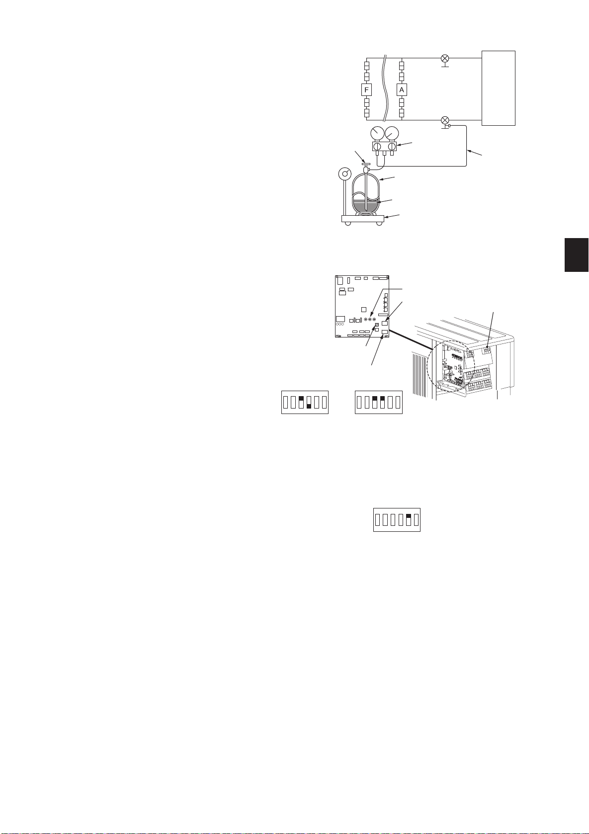
4-2. GAS CHARGE
Performgaschargetounit.
1)Connectgascylindertotheserviceportofstopvalve.
2)Performairpurgeofthepipe(orhose)comingfromrefrigerantgascylinder.
3)Replenishspeciedamountoftherefrigerant,whileoperatingtheairconditioner
for cooling.
Note:
Incaseofaddingrefrigerant,complywiththequantityspeciedfortherefrigerat-
ing cycle.
CAUTION:
Whenchargingtherefrigerantsystemwithadditionalrefrigerant,besuretouse
liquidrefrigerant.Addinggasrefrigerantmaychangethecompositionoftherefriger-
antinthesystemandaffectnormaloperationoftheairconditioner.Also,charge
theliquidrefrigerantslowly,otherwisethecompressorwillbelocked.
Tomaintain the highpressure of thegas cylinder, warm the gas cylinder with
warmwater(under40°C)duringcoldseason.Butneverusenakedreorsteam.
COOL/DRY HEAT
• Descriptionofthefunction:
Withthisfunction, once theoperationmodeis locked toeitherCOOL/DRYmodeor
HEATmode,theairconditioneroperatesinthatmodeonly.
* Changingthesettingisrequiredtoactivatethisfunction.Pleaseexplainaboutthisfunc-
tiontoyourcustomersandaskthemwhethertheywanttouseit.
[How to lock the operation mode]
1)Besuretoturnoffthemainpowerfortheairconditionerbeforemakingthesetting.
2)Setthe“3”ofSW1ontheoutdoorcontrollerboardtoONtoenablethisfunction.
3)TolocktheoperationmodeinCOOL/DRY mode,setthe“4”ofSW1onthe outdoor
controllerboardtoOFF.TolocktheoperationinHEATmode,setthesameswitchto
ON.
4)Turnonthemainpowerfortheairconditioner.
• Descriptionofthefunction:
Withthisfunction,theoperatingnoiseoftheoutdoorunitcanbeloweredbyreducingtheoperationload,forexample,duringnighttimeinCOOLmode.
However,pleasenotethatthecoolingandheatingcapacitymaylowerifthisfunctionisactivated.
* Changingthesettingisrequiredtoactivatethisfunction.Pleaseexplainaboutthisfunctiontoyourcustomersandaskthemwhethertheywanttouseit.
Union
Stopvalve
Liquid
pipe
Indoor
unit
Stopvalvewith
serviceport
Gas
pipe
Refrigerant gas
cylinder
operatingvalve
(forR410A)
Gaugemanifold
valve(forR410A)
Chargehose
(forR410A)
RefrigerantgascylinderforR410Awithsiphon
Electronic scale for refrigerant charging
Refrigerant(liquid)
Outdoor
unit
Union
Union
Union
SW1
ON
1 2 3 4 5 6
SW1
ON
1 2 3 4 5 6
SW1
ON
1 2 3 4 5 6
Lowertheoperatingnoise
[How to lower the operating noise]
1)Besureto turn off themainpowerfortheairconditionerbeforemaking the
setting.
2)Setthe“5”ofSW1ontheoutdoorcontrollerboardtoONtoenablethisfunction.
3)Turnonthemainpowerfortheairconditioner.
LED
SW1
SW871
SW2
Terminalblock
forDREDInterface
BH79A274H01_en.indd 6 2016/03/23 10:42:18
En-7
4-5. TEST RUN
• Testrunsoftheindoorunitsshouldbeperformedindividually.Seetheinstallationmanualcomingwiththeindoorunit,andmakesurealltheunitsoperate
properly.
• Ifthetestrunwithalltheunitsisperformedatonce,possibleerroneousconnectionsoftherefrigerantpipesandtheindoor/outdoorunitconnectingwires
cannotbedetected.Thus,besuretoperformthetestrunonebyone.
About the restart protective mechanism
Oncethecompressorstops,therestartpreventivedeviceoperatessothecompressorwillnotoperatefor3minutestoprotecttheairconditioner.
Wiring/piping correction function
Thisunithasawiring/pipingcorrectionfunctionwhichcorrectswiringandpipingcombination.Whenthereispossibilityofincorrectwiringandpipingcombi-
nation,andconrmingthecombinationisdifcult,usethisfunctiontodetectandcorrectthecombinationbyfollowingtheproceduresbelow.
Makesurethatthefollowingisdone.
• Powerissuppliedtotheunit.
• Stopvalvesareopen.
Note:
Duringdetection,theoperationoftheindoorunitiscontrolledbytheoutdoorunit.Duringdetection,theindoorunitautomaticallystopsoperation.Thisisnot
a malfunction.
Procedure
Pressthepiping/wiringcorrectionswitch(SW871)1minuteormoreafterturningonthe
powersupply.
• Correctioncompletesin10to20minutes.Whenthecorrectioniscompleted,itsresult
isshownbyLEDindication.Detailsaredescribedinthefollowingtable.
• Tocancelthisfunctionduringitsoperation,pressthepiping/wiringcorrectionswitch
(SW871)again.
• Whenthecorrectioncompletedwithouterror,donotpressthepiping/wiringcorrection
switch(SW871)again.
When the result was “cannot be corrected”, press thepiping/wiring correction switch
(SW871)againtocancelthisfunction.Then,conrmthewiringandpipingcombinationin
aconventionalmannerbyoperatingtheindoorunitsonebyone.
• Theoperationisdonewhilethepowerissupplied.Makesurenottocontactpartsother
thantheswitch,includingtheP.C.board.Thismaycauseelectricshockorburnbyhot
partsandlivepartsaroundtheswitch.ContactingthelivepartsmaycauseP.C.board
damage.
• TopreventelectroniccontrolP.C.boarddamage,makesuretoperformstaticelimination
beforeoperatingthisfunction.
• Thisfunctiondoesnotoperatewhentheoutsidetemperatureis0°Corbelow.
LED indication during detection:
LED1
(Red)
LED2
(Yellow)
LED3
(Green)
Lighted Lighted Once
Result of piping/wiring correction function
LED1
(Red)
LED2
(Yellow)
LED3
(Green)
Result
Lighted Not lighted Lighted
Completed
(Problemcorrectedor
normal)
Once Once Once
Notcompleted
(Detectionfailed)
Otherindications
Referto“SAFETYPRE-
CAUTIONSWHENLED
BLINKS”locatedbehind
theservicepanel.
4-6. EXPLANATION TO THE USER
• UsingtheOPERATINGINSTRUCTIONS,explaintotheuserhowtousetheairconditioner(howtousetheremotecontroller,howtoremovetheairlters,
howtoremoveorputtheremotecontrollerintheremotecontrollerholder,howtoclean,precautionsforoperation,etc.).
• RecommendtheusertoreadtheOPERATINGINSTRUCTIONScarefully.
Whenrelocatingordisposingoftheairconditioner,pumpdownthesystemfollowingtheprocedurebelowsothatnorefrigerantisreleasedintotheatmosphere.
1)Turnoffthebreaker.
2)Connectthegaugemanifoldvalvetotheserviceportofthestopvalveonthegaspipesideoftheoutdoorunit.
3)Fullyclosethestopvalveontheliquidpipesideoftheoutdoorunit.
4)Turnonthebreaker.
5)StarttheemergencyCOOLoperationonalltheindoorunits.
6)Whenthepressuregaugeshows0–0.05MPa[Gauge](approx.0–0.5kgf/cm
2
),fullyclosethestopvalveonthegaspipesideoftheoutdoorunitand
stoptheoperation.(Refertotheindoorunitinstallationmanualaboutthemethodforstoppingtheoperation.)
* Iftoomuchrefrigeranthasbeenaddedtotheairconditionersystem,thepressuremaynotdropto0–0.05MPa[Gauge](approx.0–0.5kgf/cm
2
),or
theprotectionfunctionmayoperateduetothepressureincreaseinthehigh-pressurerefrigerantcircuit.Ifthisoccurs,usearefrigerantcollectingdevice
tocollectalloftherefrigerantinthesystem,andthenrechargethesystemwiththecorrectamountofrefrigerantaftertheindoorandoutdoorunitshave
been relocated.
7)Turnoffthebreaker.Removethepressuregaugeandtherefrigerantpiping.
When pumping down the refrigerant, stop the compressor before disconnecting the refrigerant pipes.
The compressor may burst and cause injury if any foreign substance, such as air, enters the pipes.
WARNING
5. PUMPING DOWN
BH79A274H01_en.indd 7 2016/03/23 10:42:18

C
M
Y
CM
MY
CY
CMY
K
blank(A4-tombo-blank).pdf 2014/03/17 15:06:22

C
M
Y
CM
MY
CY
CMY
K
blank(A4-tombo-blank).pdf 2014/03/17 15:06:22

C
M
Y
CM
MY
CY
CMY
K
blank(A4-tombo-blank).pdf 2014/03/17 15:06:22

BH79A274H01
HEAD OFFICE: TOKYO BUILDING, 2-7-3, MARUNOUCHI, CHIYODA-KU, TOKYO 100-8310, JAPAN
BH79A274H01_cover.indd 1 2016/04/07 19:03:22