Loading ...
Loading ...
Loading ...
8
Installation
Pipe dimensions
Note: The device manufacturer does not assume any warranty
for complaints attributable to the pipe section.
■ The device achieves its optimum performance by means of a
short, straight exhaust air pipe and as large a pipe diameter
as possible.
■ As a result of long rough exhaust air pipes, many pipe bends
or diameters, the optimum extraction performance is not
achieved and fan noise is increased.
■ The pipes or hoses for laying the exhaust air line must
consist of non-combustible material.
Round pipes
An inner diameter of 150 mm, but at least 120 mm, is
recommended.
Flat ducts
The inner cross-section must correspond to the diameter of the
round pipes.
Ø 150 mm approx. 177 cm
2
Ø 120 mm approx. 113 cm
2
■ Flat ducts should have no sharp deflections.
■ Use sealing strip for deviating pipe diameters.
Checking the wall
■ The wall must be level, vertical and adequately load-bearing.
■ The depth of the boreholes must be the same length
as the screws. The wall plugs must have a secure grip.
■ The enclosed screws and wall plugs are suitable for solid
brickwork. Suitable fasteners must be used for other
structures (e.g. plasterboard, porous concrete, poroton
bricks).
■ The max. weight of the extractor hood is 40 kg.
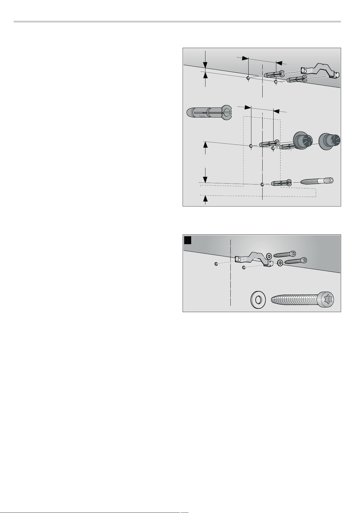
Preparing the installation
1. Mark a vertical centre line on the wall from the ceiling
to the lower edge of the extractor hood.
2. Mark positions for the screws and the contour
of the attachment area.
3. Drill five 8 mm Ø holes to a depth of 80 mm
for the attachments and press in the wall plugs flush with
the wall.
Installation
1. Screw on the fixing bracket for the flue duct. ¨
[
PP
PP
PP
PP
PP
[
$
Loading ...
Loading ...
Loading ...